WO2020090176A1 - Dispositif de traitement d'image et procédé de traitement d'image - Google Patents
Dispositif de traitement d'image et procédé de traitement d'image Download PDFInfo
- Publication number
- WO2020090176A1 WO2020090176A1 PCT/JP2019/030496 JP2019030496W WO2020090176A1 WO 2020090176 A1 WO2020090176 A1 WO 2020090176A1 JP 2019030496 W JP2019030496 W JP 2019030496W WO 2020090176 A1 WO2020090176 A1 WO 2020090176A1
- Authority
- WO
- WIPO (PCT)
- Prior art keywords
- image
- target pixel
- level
- image processing
- frequency component
- Prior art date
- Legal status (The legal status is an assumption and is not a legal conclusion. Google has not performed a legal analysis and makes no representation as to the accuracy of the status listed.)
- Ceased
Links
Images


Classifications
-
- G—PHYSICS
- G06—COMPUTING OR CALCULATING; COUNTING
- G06T—IMAGE DATA PROCESSING OR GENERATION, IN GENERAL
- G06T5/00—Image enhancement or restoration
- G06T5/90—Dynamic range modification of images or parts thereof
- G06T5/92—Dynamic range modification of images or parts thereof based on global image properties
-
- G—PHYSICS
- G06—COMPUTING OR CALCULATING; COUNTING
- G06T—IMAGE DATA PROCESSING OR GENERATION, IN GENERAL
- G06T5/00—Image enhancement or restoration
- G06T5/90—Dynamic range modification of images or parts thereof
- G06T5/94—Dynamic range modification of images or parts thereof based on local image properties, e.g. for local contrast enhancement
-
- G—PHYSICS
- G06—COMPUTING OR CALCULATING; COUNTING
- G06T—IMAGE DATA PROCESSING OR GENERATION, IN GENERAL
- G06T1/00—General purpose image data processing
-
- G—PHYSICS
- G06—COMPUTING OR CALCULATING; COUNTING
- G06T—IMAGE DATA PROCESSING OR GENERATION, IN GENERAL
- G06T5/00—Image enhancement or restoration
- G06T5/50—Image enhancement or restoration using two or more images, e.g. averaging or subtraction
-
- G—PHYSICS
- G06—COMPUTING OR CALCULATING; COUNTING
- G06T—IMAGE DATA PROCESSING OR GENERATION, IN GENERAL
- G06T5/00—Image enhancement or restoration
- G06T5/80—Geometric correction
-
- H—ELECTRICITY
- H04—ELECTRIC COMMUNICATION TECHNIQUE
- H04N—PICTORIAL COMMUNICATION, e.g. TELEVISION
- H04N1/00—Scanning, transmission or reproduction of documents or the like, e.g. facsimile transmission; Details thereof
- H04N1/40—Picture signal circuits
- H04N1/407—Control or modification of tonal gradation or of extreme levels, e.g. background level
-
- H—ELECTRICITY
- H04—ELECTRIC COMMUNICATION TECHNIQUE
- H04N—PICTORIAL COMMUNICATION, e.g. TELEVISION
- H04N23/00—Cameras or camera modules comprising electronic image sensors; Control thereof
- H04N23/60—Control of cameras or camera modules
-
- H—ELECTRICITY
- H04—ELECTRIC COMMUNICATION TECHNIQUE
- H04N—PICTORIAL COMMUNICATION, e.g. TELEVISION
- H04N5/00—Details of television systems
- H04N5/14—Picture signal circuitry for video frequency region
- H04N5/20—Circuitry for controlling amplitude response
-
- G—PHYSICS
- G06—COMPUTING OR CALCULATING; COUNTING
- G06T—IMAGE DATA PROCESSING OR GENERATION, IN GENERAL
- G06T2207/00—Indexing scheme for image analysis or image enhancement
- G06T2207/20—Special algorithmic details
- G06T2207/20172—Image enhancement details
- G06T2207/20208—High dynamic range [HDR] image processing
Definitions
- the present disclosure relates to an image processing device and an image processing method. Specifically, the present invention relates to an image processing device and an image processing method for processing image data generated by imaging.
- imaging devices such as a digital still camera, a digital video camera (for example, a camera-integrated recorder), a surveillance camera, and the like, which image a subject such as a person, an animal, or a vehicle to generate image data, have been widely used.
- an imaging device that generates an appropriate image by performing various kinds of image processing on the generated image data is widely used.
- the image generated by the image pickup device includes a scene with a large difference in brightness (for example, a backlit scene)
- a bright portion in the generated image is saturated to cause overexposure or the generated image.
- blackout occurs in the dark part of. Therefore, an image pickup apparatus has been proposed that can appropriately perform gradation correction even for a scene with a large difference in brightness (for example, a backlit scene) (see, for example, Patent Document 1).
- object recognition is performed using the image generated by the imaging device.
- a changed portion for example, edge
- the recognition rate decreases when the object recognition is performed using the characteristics of the changed portion in the image. May occur.
- the present disclosure has been made in view of the problems described above, and an object thereof is to generate an image that can appropriately perform object recognition.
- a first aspect of the present disclosure is an image processing apparatus including an image processing unit that corrects a level of a target pixel forming an image based on a low frequency component in a peripheral image of the target pixel, an image processing method thereof, and A program that causes a computer to execute the method.
- the image processing unit does not correct the level of the target pixel when the level of the target pixel is smaller than a first threshold, and the level of the target pixel is the first level.
- the level of the target pixel may be corrected if the second threshold value, which is a value greater than the threshold value, is used as a reference.
- the image processing unit when the level of the target pixel is included in a predetermined range based on the first threshold value and the second threshold value, a peripheral image of the target pixel. Whether or not to correct the level of the target pixel may be determined based on the high frequency component in.
- the image processing unit corrects the level of the target pixel when the high frequency component is smaller than a third threshold, and the high frequency component is a value larger than the third threshold.
- the level of the target pixel may not be corrected if it is larger than the fourth threshold value.
- the image processing unit corrects the level of the target pixel when the high frequency component is included in a predetermined range based on the third threshold value and the fourth threshold value. It is also possible to perform a blending process of blending the object and the object whose level of the target pixel is not corrected.
- the image processing unit may generate a gain for correcting the level of the target pixel based on the low frequency component.
- the image is a composite image generated by combining a first image generated under different conditions and a second image that is a darker image than the first image
- the image The processing unit may correct the level of the target pixel forming the composite image based on the low-frequency component in the peripheral image of the first pixel corresponding to the target pixel in the first image.
- the image processing unit is configured to, when the level of the second pixel in the second image corresponding to the target pixel forming the composite image is low based on a first threshold value.
- the level of the target pixel may be corrected without correcting the level of the target pixel, when the level of the second pixel is higher than the second threshold value that is larger than the first threshold value.
- the image processing unit may determine whether the level of the second pixel is within the predetermined range based on the first threshold value and the second threshold value. Whether to correct the level of the target pixel forming the composite image may be determined based on the high frequency component in the peripheral image.
- the image processing unit corrects the level of the target pixel forming the composite image when the high frequency component is smaller than a third threshold, and the high frequency component is the first pixel. If the fourth threshold value, which is a value greater than the three threshold values, is larger than the third threshold value, the level of the target pixel may not be corrected.
- the image processing unit when the high-frequency component is included in a predetermined range based on the third threshold value and the fourth threshold value, the target forming the composite image. It is also possible to perform blending processing for blending a pixel whose level is corrected and a pixel whose level of the target pixel is not corrected.
- the image processing unit may generate a gain for correcting the level of the target pixel forming the composite image based on the low frequency component in the peripheral image of the first pixel. Good.
- Adopting such a mode brings about the effect of correcting the level of the target pixel forming the image based on the low frequency component in the peripheral image of the target pixel.
- FIG. 4 is a diagram showing an example of a relationship between each image used in a correction process by the image processing unit 200 according to the first embodiment of the present disclosure, a target pixel, and a peripheral image.
- FIG. 6 is a diagram showing a relationship between level thresholds TH1 and TH2 used for determining a correction process by a mask processing unit 252 according to the first embodiment of the present disclosure and a level L1 of a target pixel.
- FIG. 5 is a diagram showing a relationship between thresholds TH3 and TH4 of levels used for determining a correction process by a mask processing unit 252 according to the first embodiment of the present disclosure, and a high frequency component HF1 extracted from a peripheral image.
- FIG. 6 is a diagram schematically showing a flow of determination of correction processing by a mask processing unit 252 according to the first embodiment of the present disclosure. 6 is a flowchart illustrating an example of a processing procedure of a correction process performed by the imaging device 100 according to the first embodiment of the present disclosure. 6 is a flowchart illustrating an example of a processing procedure of a correction process performed by the imaging device 100 according to the first embodiment of the present disclosure.
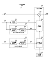
- FIG. 1 is a diagram illustrating a configuration example of an imaging device 100 according to the first embodiment of the present disclosure.
- the imaging device 100 includes a sensor 110, an exposure control unit 120, an HDR (high dynamic range) combining unit 130, a control unit 140, an operation receiving unit 150, and an image processing unit 200.
- the imaging apparatus 100 is realized by, for example, a device that generates a moving image or a still image used when performing object recognition using the characteristics of a changed portion (for example, edge) in an image.
- the image pickup apparatus 100 is an example of the image processing apparatus described in the claims.
- the sensor 110 is an image sensor (image sensor) that converts the light of the subject incident through the lens into an electric signal (image data) under the control of the control unit 140.
- the sensor 110 also outputs the electric signal (image data) to the exposure control unit 120 via the signal line 111.
- a CCD (Charge Coupled Device) or CMOS (Complementary Metal Oxide Semiconductor) sensor can be used as the sensor 110.
- the exposure control unit 120 performs various exposure controls such as shutter control, gain control, and flash control based on the control of the control unit 140.
- the exposure control unit 120 uses the electric signal (image data) output from the sensor 110 based on various setting contents, and a plurality of images (short-term accumulated image and long-term accumulated image) having different setting conditions. Image data is generated.
- the exposure control unit 120 outputs the generated image data of the long-time accumulated image to the HDR synthesizing unit 130 via the signal line 121, and the generated image data of the short-time accumulated image via the signal line 122. It is output to the HDR synthesis unit 130.
- the HDR synthesizing unit 130 Under the control of the control unit 140, the HDR synthesizing unit 130 performs an HDR synthesizing process on the image data (short-time accumulated image and long-term accumulated image) output from the exposure controller 120 to generate an HDR synthetic image. It is a thing. For example, when the level of the target pixel in the long-time accumulated image exceeds the reference value, the combining unit 130 performs the correction process based on the short-time accumulated image having the same coordinates as the target pixel.
- the HDR synthesizing unit 130 can also compress the HDR synthetic image using a predetermined compression technique.
- the HDR synthesizing unit 130 can compress the synthetic image into 8-bit gradation.
- the HDR synthesizing unit 130 synthesizes a plurality of images having different brightness in order to visually recognize an object, and performs tone compression using tone reduction to convert a high dynamic range image into a low tone format. Can be output to.
- the output range can be changed by changing the compression target value.
- the HDR synthesizing unit 130 outputs the generated HDR synthetic image (for example, an image compressed to 8-bit gradation) to the image processing unit 200 via the signal line 131. Further, the HDR synthesizing unit 130 outputs image data before performing the HDR synthesizing process on the images (short-time accumulated image and long-term accumulated image) output from the exposure control unit 120 to the image processing unit 200. That is, the HDR synthesizing unit 130 outputs the image data of the long-time accumulated image to the image processing unit 200 via the signal line 132, and outputs the image data of the short-time accumulated image to the image processing unit 200 via the signal line 133. To do.
- the control unit 140 controls each unit of the imaging device 100 based on a control program stored in a memory (not shown). The control unit 140 also controls each unit based on the operation input accepted by the operation accepting unit 150.
- the control unit 140 is realized by, for example, a CPU (Central Processing Unit).
- the operation receiving unit 150 is an operation receiving unit that receives an operation input made by a user, and outputs operation information according to the received operation input to the control unit 140.
- the operation reception unit 140 is realized by, for example, various operation members (for example, buttons, switches, and touch panels) and external operation members (for example, a mouse and a keyboard).
- the image processing unit 200 performs various types of image processing on the image data output from the HDR synthesizing unit 130, and outputs the image processed image data via the signal line 254.
- the image data subjected to the image processing by the image processing unit 200 is used for object recognition, for example.
- the image data subjected to the image processing by the image processing unit 200 may be stored in a storage medium and used for object recognition.
- the configuration of the image processing unit 200 will be described in detail with reference to FIG.
- the object recognition is, for example, object recognition (particularly, biometric recognition) using the characteristics of a changed portion (for example, edge) in the image.
- Object recognition using the feature of the changed part in the image is, for example, CNN (Convolutional Neural Network), HOG (Histogram Oriented Gradient), and SIFT (Scale-Invariant Feature Transform).
- FIG. 2 is a diagram illustrating a configuration example of the image processing unit 200 according to the first embodiment of the present disclosure.
- the image processing unit 200 includes a level determination unit 210, an edge / texture determination unit 220, an illumination component extraction unit 230, a correction value setting unit 240, and a correction processing unit 250.
- the level determination unit 210 determines the level of each pixel forming the image data (short-time accumulated image data) output from the HDR synthesizing unit 130 (shown in FIG. 1) via the signal line 133. Then, the level determination unit 210 outputs the determined level to the mask processing unit 252 via the signal line 211.
- a brightness value density value and gradation value
- a pixel value level of the sensor output itself
- the pixel value changes depending on the structure of the color filter of the sensor, it is preferable to use a brightness value that can maintain performance regardless of the structure of the color filter. Therefore, in the first embodiment, an example in which the brightness value is used as the pixel level is shown.
- the edge / texture determination unit 220 includes a peripheral image acquisition unit 221 and a high frequency component extraction unit 222.
- the peripheral image acquisition unit 221 exists around the target pixel among the pixels forming the image data (short-time accumulated image data) output from the HDR synthesis unit 130 (shown in FIG. 1) via the signal line 133. The image of a predetermined range is obtained. Then, the peripheral image acquisition unit 221 outputs the image data of the acquired image (peripheral image) to the high frequency component extraction unit 222.
- the target pixel and the peripheral image will be described in detail with reference to FIG.
- the high frequency component extraction unit 222 extracts high frequency components from the image data of the peripheral image output from the peripheral image acquisition unit 221. Then, the high frequency component extraction unit 222 outputs the extracted high frequency component (high frequency component value) to the mask processing unit 252 via the signal line 223.
- the illumination component extraction unit 230 includes a peripheral image acquisition unit 231 and a low frequency component extraction unit 232.
- the peripheral image acquisition unit 231 exists around the target pixel among the pixels forming the image data (long-term accumulated image data) output from the HDR synthesizing unit 130 (shown in FIG. 1) via the signal line 132. The image of a predetermined range is obtained. Then, the peripheral image acquisition unit 231 outputs the image data of the acquired image (peripheral image) to the low frequency component extraction unit 232.
- the target pixel and the peripheral image will be described in detail with reference to FIG.
- the low-frequency component extraction unit 232 extracts a low-frequency component from the image data of the peripheral image output from the peripheral image acquisition unit 231. Then, the low frequency component extraction unit 232 outputs the extracted low frequency component (low frequency component value) to the control gain generation unit 251 via the signal line 233.
- the correction value setting unit 240 holds the parameter (setting value) used when the control gain generating unit 251 generates the control gain, and the held parameter (setting value) is stored in the control gain generating unit 251. Supply.
- the parameter (setting value) held in the correction value setting unit 240 can be changed based on the user operation using the operation receiving unit 150 (shown in FIG. 1). ..
- a compression target value can be used as the set value.
- the average brightness value of the learning image used for object recognition may be used as the set value.
- the correction processing unit 250 includes a control gain generation unit 251, a mask processing unit 252, and a multiplier 253.
- the control gain generation unit 251 receives the input image (signal line) based on the value (set value) supplied from the correction value setting unit 240 and the value (low frequency component value) output from the low frequency component extraction unit 232. 131) to generate a gain for multiplying the target pixel. Further, the control gain generation unit 251 outputs the generated gain to the mask processing unit 252.
- the mask processing unit 252 based on the value (luminance value) output from the level determination unit 210 and the value (high frequency component value) output from the high frequency component extraction unit 222, targets in the input image (signal line 131). It is for determining whether or not to perform pixel correction processing. Specifically, the mask processing unit 252 outputs the input image (signal) based on the value (luminance value) output from the level determination unit 210 and the value (high frequency component value) output from the high frequency component extraction unit 222. It is determined whether the target pixel on line 131) is multiplied by the gain. In addition, when the mask processing unit 252 determines to multiply the target pixel in the input image (HDR composite image) by the gain, the mask processing unit 252 outputs the gain output from the control gain generation unit 251 to the multiplier 253.
- the multiplier 253 multiplies the image data (HDR composite image) output from the HDR composition unit 130 (shown in FIG. 1) via the signal line 131 by the gain output from the mask processing unit 252. Yes, the multiplication result is output to the signal line 254.
- FIG. 3 is a diagram showing an example of the relationship between each image used in the correction processing by the image processing unit 200 according to the first embodiment of the present disclosure, the target pixel, and the peripheral image.
- the HDR synthetic image 300 corresponding to each image data output from the HDR synthesizing unit 130 (shown in FIG. 1), the long-time accumulated image 310, and the short-time accumulated image 320 are schematically shown by rectangles. ..
- the long-time accumulated image 310 is an example of the first image described in the claims.
- the short-time accumulated image 320 is an example of the second image described in the claims.
- the pixel to be corrected by the correction processing unit 250 is the target pixel 301, and the pixels corresponding to the positions of the pixel 301 in the long-time accumulated image 310 and the short-time accumulated image 320 are the target pixels 311 and 321. Show as.
- the peripheral images used in the correction processing by the correction processing unit 250 are shown as the peripheral images 312 and 322 by bold rectangles.
- the peripheral image 312 is an image existing around the target pixel 311 with the target pixel 311 as a center (an image existing within a predetermined range from the target pixel 312).
- the peripheral image 322 is an image existing around the target pixel 321 with the target pixel 321 being the center (an image existing within a predetermined range from the target pixel 322).
- the range of the peripheral image 312 is set to 25 pixels ⁇ 25 pixels, and the range of the peripheral image 322 is set. Can be set to 5 pixels ⁇ 5 pixels.
- the ranges of the peripheral images 312 and 322 are examples, and other ranges may be used.
- the ranges of the peripheral images 312 and 322 may be determined according to the spatial frequency information of the image to be acquired.
- the range of the peripheral images 312 and 322 can be determined based on the required cutoff frequency.
- the cutoff frequency can be calculated by the following equation 1.
- N is the number of pixels included in the image range.
- Nyquist frequency 1 / (pixel pitch ⁇ 2). It should be noted that the pixel pitch means an interval between center lines between pixels forming the image sensor.
- the range of the peripheral images 312 and 322 can be determined by obtaining N, which is the required cutoff frequency, based on the above-described formula 1.
- the correction processing unit 250 determines whether or not the correction processing is necessary for all the pixels forming the HDR composite image 300. Specifically, in the HDR composite image 300, the correction processing unit 250 advances the target pixel 301 pixel by pixel from the position of the upper left corner to the position of the lower right corner, as indicated by the arrow 302. That is, the target pixel 301 advances one pixel in the horizontal direction from the position of the upper left corner in the HDR composite image 300, and when reaching the right end position, returns to the left end position and advances one pixel in the vertical direction. Similarly, the target pixel 301 advances by one pixel in the horizontal direction until reaching the position of the lower right corner, and when reaching the position of the right end, returns to the position of the left end and advances by one pixel in the vertical direction.
- low frequency components are extracted from the peripheral image 312 in the long-time accumulated image 310.
- the low-frequency component extraction unit 232 uses the average of the luminance values of the pixels forming the peripheral image (25 pixels ⁇ 25 pixels) acquired by the peripheral image acquisition unit 231 (shown in FIG. 2). Calculate the value. Then, the low frequency component extraction unit 232 outputs the average value to the control gain generation unit 251 (shown in FIG. 2) as a low frequency component.
- a predetermined filter circuit for example, a filter circuit that extracts low frequency components (for example, a low-pass filter) may be used as the low frequency component extraction unit 232.
- control gain generation unit 251 generates a gain based on the low frequency component extracted by the low frequency component extraction unit 232. Specifically, the control gain generation unit 251 performs a predetermined calculation (setting value) based on the value (setting value) set in the correction value setting unit 240 and the low frequency component extracted from the peripheral image 312. / Low frequency component value). Note that this calculation (setting value / low frequency component value) is an example, and the value (setting value) set in the correction value setting unit 240 and the low frequency component extracted from the peripheral image 312 are used. The gain may be generated by another calculation.
- the level of the brightness value of the target pixel 321 in the short-time accumulated image 320 is determined.
- the level determination unit 210 (shown in FIG. 2) acquires the luminance value of the target pixel 321 in the short-time accumulated image 320 and outputs it to the mask processing unit 252 (shown in FIG. 2).
- high frequency components are extracted from the peripheral image 322 in the short-time accumulated image 320.
- the high frequency component extraction unit 222 uses the average value of the brightness values of the respective pixels forming the peripheral image (5 pixels ⁇ 5 pixels) acquired by the peripheral image acquisition unit 221 (shown in FIG. 2). Is calculated, and a value obtained by subtracting this average value from the luminance value of the target pixel 321 is calculated. Then, the high frequency component extraction unit 222 outputs the calculated value (value obtained by subtracting the average value from the luminance value of the target pixel 321) as a high frequency component to the mask processing unit 252 (shown in FIG. 2).
- a predetermined filter circuit for example, a filter circuit (for example, a high pass filter) that extracts high frequency components) may be used as the high frequency component extraction unit 222.
- the mask processing unit 252 determines whether or not to perform the correction process based on the luminance value of the target pixel 321 acquired by the level determination unit 210 and the high frequency component extracted by the high frequency component extraction unit 222. .. The determination process will be described in detail with reference to FIGS. 4 to 6.
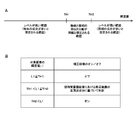
- FIG. 4 is a diagram showing the relationship between the level thresholds TH1 and TH2 used for determining the correction processing by the mask processing unit 252 according to the first embodiment of the present disclosure and the level L1 of the target pixel.
- FIG. 4A shows the relationship between the brightness value of the target pixel 321 in the short-time accumulated image 320 (shown in FIG. 3C) and the threshold values TH1 and TH2.
- the horizontal axis shown in FIG. 4A is an axis indicating the level of the luminance value of the target pixel, and the level increases from the left side to the right side.
- Thresholds TH1 and TH2 are thresholds (reference levels) used when deciding on / off of the correction process, and TH1 ⁇ TH2.
- the threshold value TH1 for example, a compression target value can be used, similar to the setting value described above. Further, the average brightness value of the learning image used for object recognition may be used as the threshold value TH1. Note that the threshold value TH1 shown here is an example, and may be changed as appropriate according to user settings.
- the threshold TH2 can be set to a level at which, for example, in the HDR synthesizing process, synthesizing a short-time accumulated image (dark image) and a long-term accumulated image (bright image) is started.
- the level at which synthesis of the short-time accumulated image and the long-term accumulated image is started is, for example, about 90% to 95% of the value at which the level of the long-term accumulated image (bright image) is saturated.
- the level at which synthesis of the short-time accumulated image and the long-term accumulated image is started is 90, which is a value at which the level of the sensor capable of generating the long-term accumulated image (bright image) is saturated. It can be set to a value of about% -95%.
- the luminance value L1 of the target pixel 321 in the short-time accumulated image 320 (shown in FIG. 3C), the high-frequency component extracted from the peripheral image 322 in the short-time accumulated image 320, and ON / OFF of the correction process. Shows the relationship.
- the target pixel 321 in the short-time accumulated image 320 when the luminance value L1 of the target pixel 321 in the short-time accumulated image 320 is equal to or less than the threshold TH1, the target pixel 321 may be included in the range in which it is assumed that there are many object components. high. Therefore, when the luminance value L1 of the target pixel 321 in the short-time accumulated image 320 is less than or equal to the threshold TH1, the correction process is turned off as shown in FIG. 4B. That is, the gain by which the target pixel in the input image (HDR composite image) is multiplied is set to 1.
- the target when the luminance value L1 of the target pixel 321 in the short-time accumulated image 320 (shown in FIG. 3C) is larger than the threshold value TH2, the target is within the range where the illumination component is assumed to be large. It is highly possible that the pixel 321 is included. Therefore, when the luminance value L1 of the target pixel 321 in the short-time accumulated image 320 is larger than the threshold value TH2, the correction process is turned on to eliminate the illumination component, as shown in FIG. 4B. That is, the gain by which the target pixel in the input image (HDR composite image) is multiplied is defined as “setting value / low frequency component value”.
- the value (setting value) held in the correction value setting unit 240 and the threshold value TH1 are the same value.
- the short-time accumulated image 320 is a dark image
- the long-term accumulated image is a bright image. Therefore, when the luminance value L1 of the target pixel 321 of the short-time accumulated image 320 is larger than the threshold value TH1, the low-frequency component extracted from the peripheral image 312 of the long-term accumulated image 310 (the average of the luminance values of the respective pixels). Value) is assumed to be a value larger than the threshold value TH1. Therefore, the calculated gain (setting value / low frequency component value) is a value less than 1.
- the luminance value L1 of the target pixel 321 in the short-time accumulated image 320 (shown in FIG. 3C) is larger than the threshold TH1 and is equal to or smaller than the threshold TH2, whether there are many components of the object.
- the target pixel 321 is likely to be included in a range where it is difficult to determine whether there are many illumination components. Therefore, when the brightness value L1 of the target pixel 321 in the short-time accumulated image 320 is larger than the threshold TH1 and equal to or less than the threshold TH2, as shown in FIG. 4B, it is extracted from the peripheral image 322 in the short-time accumulated image 320. On / off of the correction process is determined based on the high frequency component. An example of determining the correction process will be described in detail with reference to FIG.
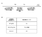
- FIG. 5 is a diagram showing a relationship between level thresholds TH3 and TH4 used for determining correction processing by the mask processing unit 252 according to the first embodiment of the present disclosure, and a high frequency component HF1 extracted from a peripheral image. Is.
- FIG. 5A shows the relationship between the high frequency component HF1 extracted from the peripheral image 322 in the short-time accumulated image 320 and the thresholds TH3 and TH4.
- the horizontal axis shown in FIG. 5A is an axis indicating the level of the high frequency component extracted from the peripheral image in the short-time accumulated image, and the level increases from the left side to the right side.
- Thresholds TH3 and TH4 are thresholds (reference levels) used when deciding on / off of the correction process, and TH3 ⁇ TH4.
- the thresholds TH3 and TH4 can be set, for example, by finely adjusting according to the scene of the entire screen in the image. For example, the adjustment can be performed while watching the reaction (for example, the recognition rate of the object) in the object recognition processing (for example, CNN, HOG, and SIFT). For example, when the spatial frequency of the scene of the entire screen in the image is high (for example, in the case of an image with many high frequency regions), both thresholds TH3 and TH4 can be set high. On the other hand, when the spatial frequency of the scene of the entire screen in the image is low (for example, in the case of an image having many low frequency regions), both thresholds TH3 and TH4 can be set low. Further, in the case where there are various spatial frequencies of the scene of the entire screen in the image, the interval between the thresholds TH3 and TH4 can be set to be widened.
- FIG. 5B shows the relationship between the high-frequency component HF1 extracted from the peripheral image 322 in the short-time accumulated image 320, the threshold values TH3 and TH4, and ON / OFF of the correction process.
- the high frequency component HF1 extracted from the peripheral image 322 in the short-time accumulated image 320 is less than or equal to the threshold value TH3
- the component of the object for example, edge component
- the target pixel 321 is included in the range assumed to be. Therefore, when the high frequency component HF1 extracted from the peripheral image 322 in the short-time accumulated image 320 is less than or equal to the threshold value TH3, as shown in FIG. 5B, the correction process is turned on to eliminate the illumination component. .. That is, the gain by which the target pixel in the input image (HDR composite image) is multiplied is defined as “setting value / low frequency component value”.
- the high frequency component HF1 extracted from the peripheral image 322 in the short-time accumulated image 320 (shown in FIG. 3C) is larger than the threshold TH4, the component of the object (for example, edge component). It is highly possible that the target pixel 321 is included in the range that is assumed to be large. Therefore, when the high frequency component HF1 extracted from the peripheral image 322 in the short-time accumulated image 320 is larger than the threshold value TH4, the correction process is turned off as shown in FIG. 5B. That is, the gain by which the target pixel in the input image (HDR composite image) is multiplied is set to 1.
- the high frequency component HF1 extracted from the peripheral image 322 is larger than the threshold TH3 and is equal to or smaller than the threshold TH4, it is determined whether there are many object components or many illumination components. It is highly possible that the target pixel 321 is included in the range that is difficult to do. Therefore, when the high frequency component HF1 extracted from the peripheral image 322 is larger than the threshold value TH3 and is equal to or smaller than the threshold value TH4, the image blending process is performed as shown in FIG. 5B.
- the image blending process is a process of blending the image subjected to the correction process (correction process on image) and the image not subjected to the correction process (correction process off image) at a predetermined ratio.
- the blend ratio BR1 for blending the correction processing on image and the correction processing off image is calculated based on the following Expression 2.
- BR1 (HF1-TH3) / (TH4-TH3) Equation 2
- This blending process can be performed by the correction processing unit 250.
- the control gain generation unit 251 calculates a gain based on the above-described blend rate BR1, and the calculated gain is input to the multiplier 253 and multiplied with the image data. Thereby, blending processing can be performed.
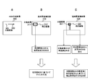
- FIG. 6 is a diagram schematically showing a flow of determination of correction processing by the mask processing unit 252 according to the first embodiment of the present disclosure.
- the level determination unit 210 determines the level of the brightness value of the target pixel 321 in the short-time accumulated image 320, and the high-frequency component extraction unit 222 extracts the peripheral image 322 from the short-term accumulated image 320. Extract high frequency components.
- the mask processing unit 252 determines whether or not the luminance value L1 of the target pixel 321 is less than or equal to the threshold value TH1. Then, when the luminance value L1 of the target pixel 321 is less than or equal to the threshold value TH1, the mask processing unit 252 determines to turn off the correction process. In this case, the gain by which the target pixel in the input image (HDR composite image) is multiplied is 1.
- the mask processing section 252 determines whether the luminance value L1 of the target pixel 321 is larger than the threshold TH2. Then, when the luminance value L1 of the target pixel 321 is larger than the threshold value TH2, the mask processing unit 252 determines to turn on the correction process. In this case, the multiplier 253 multiplies the target pixel in the input image (HDR composite image) by the gain (setting value / low frequency component value) generated by the control gain generating unit 251.
- the mask processing unit 252 determines whether the high frequency component HF1 is equal to or less than the threshold TH3. Then, when the high frequency component is equal to or lower than the threshold TH3, the mask processing unit 252 determines to turn on the correction processing. In this case, the multiplier 253 multiplies the target pixel in the input image (HDR composite image) by the gain (setting value / low frequency component value) generated by the control gain generating unit 251.
- the mask processing unit 252 determines whether the high frequency component is larger than the threshold TH4. Then, when the high frequency component is larger than the threshold TH4, the mask processing unit 252 determines to turn off the correction processing. In this case, the gain by which the target pixel in the input image (HDR composite image) is multiplied is 1.
- the mask processing unit 252 determines to perform the image blending process. This blending process is performed based on the blend rate BR1 calculated by using the above-described equation 2.
- the image processing unit 200 can extract the illumination component in the image (for example, the pixel whose luminance value L1 is larger than the threshold TH1) and correct the pixel level of the illumination component. That is, the image processing unit 200 can preferentially correct a component having a high luminance value in the image.
- the image processing unit 200 can extract a high illuminance component (low frequency component in the peripheral image 312 of the long-time accumulated image 310) in the image and use it for correcting the pixel level of the illumination component described above.
- the image processing unit 200 generates a gain based on the high illuminance component (low frequency component in the peripheral image 312 of the long-time accumulated image 310) in the image, and uses this gain to calculate the pixel of the illumination component described above. The level can be corrected.
- the image processing unit 200 can extract a low illuminance component (high-frequency component in the peripheral image 322 of the short-time accumulated image 320) in the image and use it for correcting the pixel level of the illumination component described above.
- the image processing unit 200 can determine a place assumed to be an object in the image based on the low illuminance component in the image (high-frequency component in the peripheral image 322 of the short-time accumulated image 320). Then, the image processing unit 200 can determine whether to correct the pixel level of the illumination component described above based on the determination result. Thereby, the correction of the edge portion in the image can be suppressed.
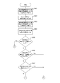
- FIG. 7 and 8 are flowcharts illustrating an example of a processing procedure of a correction process performed by the image capturing apparatus 100 according to the first embodiment of the present disclosure. Note that this operation example will be described with reference to each configuration shown in FIG. 2 and each image shown in FIG.
- the low frequency component extraction unit 232 extracts low frequency component values from the peripheral image 312 (long-time accumulated image 310) acquired by the peripheral image acquisition unit 231 (step S501).
- control gain generation unit 251 generates a gain based on the value (setting value) set in the correction value setting unit 240 and the extracted low frequency component (step S502).
- the high frequency component extraction unit 222 extracts high frequency components from the peripheral image 322 (short-time accumulated image 320) acquired by the peripheral image acquisition unit 221 (step S503).
- the level determination unit 210 determines the level by acquiring the brightness value of the target pixel 321 in the short-time accumulated image 320 (step S504).
- the mask processing unit 252 determines whether or not the luminance value L1 of the target pixel 321 in the short-time accumulated image 320 is less than or equal to the threshold TH1 (step S505). Then, when the luminance value L1 of the target pixel 321 in the short-time accumulated image 320 is equal to or less than the threshold value TH1 (step S505), the mask processing unit 252 determines to turn off the correction process (step S510). In this case, the gain by which the target pixel 301 in the input image (HDR composite image 300) is multiplied is set to 1 (step S510).
- the mask processing unit 252 sets the brightness value L1 of the target pixel 321 in the short-time accumulated image 320 to the threshold value. It is determined whether it is larger than TH2 (step S506). Then, when the luminance value L1 of the target pixel 321 in the short-time accumulated image 320 is larger than the threshold value TH2 (step S506), the mask processing unit 252 determines to turn on the correction process (step S511). In this case, the multiplier 253 multiplies the target pixel 301 in the input image (HDR composite image 300) by the gain (setting value / low frequency component value) generated by the control gain generating unit 251 (step S511). ..
- the mask processing unit 252 determines whether the high frequency component HF1 is less than or equal to the threshold TH3. (Step S507). Then, when the high frequency component HF1 is equal to or less than the threshold value TH3 (step S507), the mask processing unit 252 determines to turn on the correction processing (step S511). In this case, the multiplier 253 multiplies the target pixel 301 in the input image (HDR composite image 300) by the gain (setting value / low frequency component value) generated by the control gain generating unit 251 (step S511). ..
- the mask processing unit 252 determines whether the high frequency component HF1 is greater than the threshold TH4 (step S508). Then, when the high frequency component HF1 is larger than the threshold value TH4 (step S508), the correction process is turned off (step S510). In this case, the gain by which the target pixel 301 in the input image (HDR composite image 300) is multiplied is set to 1 (step S510).
- the mask processing unit 252 determines to perform image blending processing (step S509). This blending process is performed based on the blend rate BR1 calculated by using the above-described equation 2.
- the image processing unit 200 can correct the level of the target pixel 301 forming the HDR composite image 300 (shown in FIG. 3A) based on the low-frequency component in the peripheral image of the target pixel 301. Specifically, the image processing unit 200 sets the level of the target pixel 301 to the peripheral image 312 of the target pixel 311 corresponding to the target pixel 301 in the peripheral image of the target pixel 301 (the long-time accumulated image 310 (shown in FIG. 3B)). ) Can be corrected based on the low frequency component in
- the image processing unit 200 generates a gain for correcting the level of the target pixel 301 based on the low frequency component in the peripheral image of the target pixel 301. Specifically, the image processing unit 200 uses, as the peripheral image of the target pixel 301, the peripheral image 312 of the target pixel 311 corresponding to the target pixel 301 in the long-time accumulated image 310 (shown in FIG. 3B). A gain for correcting the level of 301 is generated.
- the image processing unit 200 does not correct the level of the target pixel when the level of the target pixel is smaller than the first threshold (threshold TH1), and the level of the target pixel is based on the second threshold (threshold TH2).
- the image processing unit 200 sets the level of the target pixel 321 in the short-time accumulated image 320 (shown in FIG. 3C) corresponding to the target pixel 301 of the HDR composite image 300 based on the first threshold (threshold TH1). If it is smaller, the level of the target pixel 301 is not corrected.
- the image processing unit 200 sets the target pixel 301 Correct the level.
- the image processing unit 200 determines the high frequency component in the peripheral image of the target pixel. It is possible to determine whether to correct the level of the target pixel based on
- the predetermined range based on the first threshold value (threshold value TH1) and the second threshold value (threshold value TH2) is, for example, a range from the threshold value TH1 to the threshold value TH2 shown in FIG. 4A. Then, when the level of the target pixel 321 is included in the range, the image processing unit 200 determines whether to correct the level of the target pixel 301 based on the high frequency component in the peripheral image 322 of the target pixel 321. ..
- the image processing unit 200 can correct the level of the target pixel when the high frequency component in the peripheral image of the target pixel is small with the third threshold (threshold TH3) as a reference.
- the image processing unit 200 can prevent the level of the target pixel from being corrected when the high frequency component is large on the basis of the fourth threshold value (threshold value TH4).
- the image processing unit 200 corrects the level of the target pixel 301 when the high frequency component in the peripheral image 322 of the target pixel 321 is smaller than the third threshold (threshold TH3).
- the image processing unit 200 does not correct the level of the target pixel 301 when the high frequency component is large on the basis of the fourth threshold value (threshold value TH4).
- the image processing unit 200 performs the blending process when the high frequency component in the peripheral image of the target pixel is included in the predetermined range based on the third threshold value (threshold value TH3) and the fourth threshold value (threshold value TH4). ..
- This blending process is a process of blending the corrected level of the target pixel 301 (shown in FIG. 3A) and the uncorrected level of the target pixel 301.
- the predetermined range based on the third threshold value (threshold value TH3) and the fourth threshold value (threshold value TH4) is, for example, a range from the threshold value TH3 to the threshold value TH4 shown in FIG. 5A.
- the image processing unit 200 performs the blending process when the high frequency component in the peripheral image 322 of the target pixel 321 (shown in FIG. 3C) in the short-time accumulated image 320 is included in the range.
- each processing procedure is shown in time series in FIGS. 7 and 8, the order of each processing procedure is not limited to the example shown in FIGS. 7 and 8.
- the processing procedures of steps S501, S503, and S504 may be performed simultaneously (or substantially simultaneously).
- the processes (steps S501 and S502) related to the generation of the gain may be omitted.
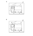
- FIG. 9 is a diagram schematically illustrating an example of an image generated by the image capturing apparatus 100 according to the first embodiment of the present disclosure. Images 10 and 20 shown in FIGS. 9A and 9B are images captured with the buses 11 and 21 traveling on the road as subjects.
- the image 10 shown in FIG. 9A is an image of the state of the bus 11 in which light is not reflected on the window glass, while the image 20 shown in FIG. 9B is exposed to strong light on the window glass and reflected. It is assumed that it is an image of the state of the bus 21 being operated. Note that in FIG. 9B, the light reflected on the window glass is schematically shown by a figure 22 for ease of explanation.
- object recognition is performed using an image generated by the imaging device 100.
- object recognition particularly biometric recognition
- object recognition is performed using the characteristics of a changed portion (for example, edge) in the image.
- the object recognition using the feature of the changed portion in the image is, for example, the above-mentioned CNN, HOG, and SIFT.
- overexposure and underexposure may occur depending on the angle and amount of light that hits the object included in the image generated by the imaging apparatus 100.
- FIGS. 9A and 9B in the case of performing object recognition using the characteristics of the changed portions in the images 10 and 20 captured from the oblique front of the buses 11 and 21, when the buses run on a road or The angle and amount of light that hits the bus changes depending on the surrounding environment. For example, when an image of a bus that exists in a dark environment at midnight is captured, there is a possibility that objects other than the inside of the bus will be completely dark and that the objects are in different categories. Further, as shown in FIG. 9B, when the bus 21 in which strong light hits the window glass and reflects the light is imaged, the light reflected from the window glass interferes with the feature amount of the bus 21. May be erased and may be recognized as an object in a different category.
- an HDR composite image generated by HDR combining a long-time exposure image and a short-time exposure image generated by imaging processing of different exposure times (a low-gradation format is obtained by gradation compression using tone reduction). It is conceivable to use a converted image).
- This HDR composite image can appropriately reproduce a scene (for example, a backlit scene) having a large difference in brightness and darkness.
- a scene for example, a backlit scene
- information of light that hits the object is left (that is, the influence of light remains).
- the feature amount in the image may change due to the gradation compression using the tone reduction. For this reason, when performing object recognition using the characteristics of the changed portion in the image, the recognition rate may decrease due to the amount of characteristics that changes due to tone reduction and the information of light that interferes with object recognition (effect of light). There is.
- the exposure control unit 120 For the image data output from the sensor 110, the exposure control unit 120 generates each image data of a short-time accumulated image and a long-term accumulated image, and the HDR synthesizing unit 130 images the HDR synthetic image. An example of generating data is shown.
- the light / dark separating unit 620 for the image data output from the sensor 610, the light / dark separating unit 620 generates image data corresponding to the short-time accumulated image and the long-term accumulated image, respectively.
- the exposure control unit 120 For the image data output from the sensor 110, the exposure control unit 120 generates each image data of a short-time accumulated image and a long-term accumulated image, and the HDR synthesizing unit 130 images the HDR synthetic image.
- An example of generating data is shown.
- the light / dark separating unit 620 for the image data output from the sensor 610, the light / dark separating unit 620 generates image data corresponding to the short-time accumulated image and the long-term
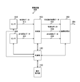
- FIG. 10 is a diagram illustrating a configuration example of the imaging device 600 according to the second embodiment of the present disclosure.
- the imaging device 600 includes a sensor 610, a light / dark separation unit 620, a control unit 140, an operation reception unit 150, and an image processing unit 200.
- the image capturing apparatus 600 is different from the image capturing apparatus 100 in that the image capturing apparatus 100 shown in FIG. 1 includes a light / dark separating unit 620 instead of the exposure control unit 120 and the HDR synthesizing unit 130. Note that, except for these points, the image pickup apparatus 100 is the same as the image pickup apparatus 100 shown in FIG. 1, and therefore, portions common to the image pickup apparatus 100 are denoted by the same reference numerals, and description thereof will be omitted.
- the sensor 610 is an image sensor that converts the light of the subject incident through the lens into an electric signal based on the control of the control unit 140, and the electric signal (image data) is subjected to image processing via the signal line 611. Output to the unit 200 and the light / dark separation unit 620.
- the light / dark separation unit 620 uses the electric signal (image data) output from the sensor 610 to generate image data of a plurality of images (dark image and bright image) having different setting conditions. To do. Then, the light / dark separation unit 620 outputs the generated image data of the bright image to the image processing unit 200 via the signal line 621, and the generated image data of the dark image via the signal line 622 to the image processing unit 200. Output to.
- the dark image corresponds to the short-time accumulated image shown in the first embodiment
- the bright image corresponds to the long-time accumulated image shown in the first embodiment.
- the light / dark separating unit 620 generates an image (image data) output from the sensor 610, which is clipped at a predetermined gradation as a bright image. Further, the light / dark separation unit 620 generates an image obtained by dividing the image (image data) output from the sensor 610 by a predetermined value as a dark image.
- the image processing unit 200 performs image processing on the image data output from the sensor 610 via the signal line 611 using the image data of the plurality of images (dark image and bright image) output from the light / dark separation unit 620. It is a thing. Since this image processing is the same as the processing shown in the first embodiment, description thereof is omitted here.
- FIG. 11 is a diagram showing a configuration example of an image pickup apparatus 700 according to the third embodiment of the present disclosure.
- the image pickup device 700 includes sensors 710 and 720, a combining unit 730, a control unit 140, an operation reception unit 150, and an image processing unit 200.
- the image pickup apparatus 700 is different from the image pickup apparatus 100 in that the image pickup apparatus 100 shown in FIG. 1 has a combining unit 720 instead of the exposure control unit 120 and the HDR combining unit 130 and has a plurality of sensors 710 and 720. different. Note that, except for these points, the image pickup apparatus 100 is the same as the image pickup apparatus 100 shown in FIG. 1, and therefore, portions common to the image pickup apparatus 100 are denoted by the same reference numerals, and description thereof will be omitted.
- the sensors 710 and 720 generate image data of a plurality of images (short-time accumulated image and long-term accumulated image) under different exposure conditions under the control of the control unit 140.
- the sensor 710 generates image data of a long-time accumulated image and outputs the image data (long-time accumulated image) to the signal line 711.
- the sensor 720 also generates image data of a short-time accumulated image and outputs the image data (short-time accumulated image) to the signal line 721.
- the synthesizing unit 730 generates an HDR synthetic image by performing an HDR synthesizing process on the image data (short-time accumulated image and long-term accumulated image) output from the sensors 710 and 720 under the control of the control unit 140. Is. For example, when the level of the target pixel in the long-time accumulated image exceeds the reference value, the combining unit 730 performs the correction process based on the short-time accumulated image having the same coordinates as the target pixel. Then, the combining unit 730 outputs the generated HDR combined image to the image processing unit 200 via the signal line 731.
- the combining unit 730 also outputs to the image processing unit 200 image data before the HDR combining process is performed on the images (short-time accumulated image and long-term accumulated image) output from the sensors 710 and 720. That is, the combining unit 730 outputs the image data of the long-time accumulated image to the image processing unit 200 via the signal line 732, and outputs the image data of the short-time accumulated image to the image processing unit 200 via the signal line 733. ..
- the image processing unit 200 converts the image data output from the synthesizing unit 730 via the signal line 731 into image data of a plurality of other images (short-time accumulated image and long-term accumulated image) output from the synthesizing unit 730. Image processing is performed by using this. Since this image processing is the same as the processing shown in the first embodiment, description thereof is omitted here.
- FIG. 12 is a diagram showing a configuration example of an imaging device 800 according to the fourth embodiment of the present disclosure.
- the image pickup apparatus 800 includes sensors 810 and 820, a combining unit 830, a control unit 140, an operation receiving unit 150, and an image processing unit 200.
- the imaging device 800 has a point that it has sensors 810 and 820 that output visible light data and invisible light data instead of the sensors 710 and 720 that output the image data of the short-time accumulated image and the long-term accumulated image, respectively. Different from device 700. It is to be noted that, except for these points, the image pickup apparatus 700 is the same as that shown in FIG. 11, and therefore, portions common to the image pickup apparatus 700 are denoted by the same reference numerals and description thereof will be omitted.
- the sensors 810 and 820 generate visible light data and invisible light data under the control of the control unit 140.
- the sensor 810 generates visible light data and outputs the visible light data to the signal line 811.
- the sensor 820 generates invisible light data and outputs the invisible light data to the signal line 821.
- the invisible light data corresponds to image data of infrared light or ultraviolet light, for example.
- the combining unit 830 generates a combined image by performing a predetermined combining process on the image data (visible light data and invisible light data) output from the sensors 810 and 820 under the control of the control unit 140. Is. Then, the combining unit 830 outputs the generated combined image to the image processing unit 200 via the signal line 831. The combining unit 830 also outputs to the image processing unit 200 image data before the combining process is performed on the images (visible light data and invisible light data) output from the sensors 810 and 820. That is, the combining unit 830 outputs the visible light data to the image processing unit 200 via the signal line 832 and the non-visible light data to the image processing unit 200 via the signal line 833.
- the image processing unit 200 performs image processing on the image data output from the synthesizing unit 830 via the signal line 831 using the visible light data and the invisible light data output from the synthesizing unit 830.
- the edge level can be acquired based on the invisible light data. Therefore, the object information that cannot be seen with visible light can be obtained using the edge level that can be acquired based on the invisible light data. Therefore, the image processing unit 200 acquires the brightness (level of the target pixel) and the low frequency component based on the visible light data, and acquires the edge (Edge) level based on the invisible light data. Then, the image processing unit 200 can determine whether the correction process is on or off based on the brightness (level of the target pixel) and the edge (Edge) level.
- the imaging device shown in the present disclosure can be applied to a digital still camera, a digital video camera (for example, a camera-integrated recorder), a monitoring device, and the like.
- drawings in the above-described embodiments are schematic, and the dimensional ratios of the respective parts and the like do not necessarily match the actual ones. Moreover, it is needless to say that the drawings may include portions having different dimensional relationships and ratios.
- processing procedure described in the above-described embodiment may be regarded as a method having these series of procedures, or as a program for causing a computer to execute the series of procedures or a recording medium storing the program. You can catch it.
- this recording medium for example, a CD (Compact Disc), a DVD (Digital Versatile Disc), a memory card, or the like can be used.
- the present technology may have the following configurations.
- An image processing apparatus including an image processing unit that corrects the level of a target pixel forming an image based on a low frequency component in a peripheral image of the target pixel.
- the image processing unit does not correct the level of the target pixel when the level of the target pixel is smaller than the first threshold, and the level of the target pixel is larger than the first threshold.
- the image processing apparatus according to (1) wherein the level of the target pixel is corrected when a certain second threshold value is large.
- the image processing unit is based on a high frequency component in a peripheral image of the target pixel.
- the image processing apparatus which determines whether or not to correct the level of the target pixel.
- the image processing unit corrects the level of the target pixel when the high frequency component is smaller than the third threshold value, and sets the fourth threshold value, which is a value higher than the third threshold value, of the high frequency component.
- the image processing device in which the level of the target pixel is not corrected when it is large as a reference.
- the image processing unit corrects the level of the target pixel and the target pixel.
- the image processing device which performs a blending process of blending the image with the image whose level is not corrected.
- the image processing device according to any one of (1) to (5), which generates a gain for correcting the level of the target pixel based on the low frequency component.
- the image is a composite image generated by combining a first image generated under different conditions and a second image that is an image darker than the first image,
- the image processing unit corrects the level of the target pixel forming the composite image based on the low frequency component in the peripheral image of the first pixel corresponding to the target pixel in the first image.
- the image processing unit corrects the level of the target pixel when the level of the second pixel in the second image corresponding to the target pixel forming the composite image is smaller than the first threshold value.
- the image processing apparatus in which the level of the target pixel is corrected when the level of the second pixel is higher than the second threshold that is a value larger than the first threshold. (9) When the level of the second pixel is included in a predetermined range based on the first threshold value and the second threshold value, the image processing unit determines the high frequency component in the peripheral image of the second pixel.
- the image processing device according to (8), wherein the image processing device determines whether to correct the level of the target pixel forming the composite image based on the basis.
- the image processing unit corrects the level of the target pixel forming the composite image when the high-frequency component is smaller than a third threshold, and the high-frequency component is a value larger than the third threshold.
- the image processing device in which the level of the target pixel is not corrected when the fourth threshold value is larger than the fourth threshold value. (11) The image processing unit corrects the level of the target pixel forming the composite image when the high frequency component is included in a predetermined range based on the third threshold value and the fourth threshold value.
- the image processing device which performs a blending process of blending a target image and a target pixel whose level of the target pixel is not corrected.
- the image processing unit generates a gain for correcting the level of the target pixel forming the composite image based on the low-frequency component in the peripheral image of the first pixel, from (7) to (11). ) The image processing device according to any one of 1). (13) An image processing method for correcting the level of a target pixel forming an image based on a low frequency component in a peripheral image of the target pixel.
- Imaging device 110, 610, 710, 720, 810, 820 Sensor 120 Exposure control unit 130 HDR composition unit 140 Control unit 150 Operation acceptance unit 200 Image processing unit 210 Level determination unit 220 Edge / texture determination unit 221, 231 peripheral image acquisition unit 222 high-frequency component extraction unit 230 illumination component extraction unit 232 low-frequency component extraction unit 240 correction value setting unit 250 correction processing unit 251 control gain generation unit 252 mask processing unit 253 multiplier 620 light-dark separation unit 730, 830 Synthesis Department
Landscapes
- Engineering & Computer Science (AREA)
- Physics & Mathematics (AREA)
- General Physics & Mathematics (AREA)
- Theoretical Computer Science (AREA)
- Multimedia (AREA)
- Signal Processing (AREA)
- Image Processing (AREA)
- Geometry (AREA)
- Studio Devices (AREA)
Abstract
Le but de la présente invention est de générer une image qui permet d'effectuer de manière appropriée une reconnaissance d'objet. Le dispositif de traitement d'image de la présente invention est pourvu d'une unité de traitement d'image pour effectuer le traitement d'une image. L'unité de traitement d'image disposée dans le dispositif de traitement d'image corrige les niveaux de pixels constituant une image. En particulier, l'unité de traitement d'image corrige le niveau d'un pixel cible constituant une image, sur la base d'une composante basse fréquence dans une image périphérique aux pixels constituant l'image cible. Ici, l'image périphérique peut comprendre le pixel cible, et comprend une pluralité de pixels présents autour du pixel cible.
Priority Applications (1)
| Application Number | Priority Date | Filing Date | Title |
|---|---|---|---|
| US17/287,991 US11887286B2 (en) | 2018-11-02 | 2019-08-02 | Image processing device and image processing method to generate image for object recognition |
Applications Claiming Priority (2)
| Application Number | Priority Date | Filing Date | Title |
|---|---|---|---|
| JP2018-207286 | 2018-11-02 | ||
| JP2018207286A JP2020071809A (ja) | 2018-11-02 | 2018-11-02 | 画像処理装置および画像処理方法 |
Publications (1)
| Publication Number | Publication Date |
|---|---|
| WO2020090176A1 true WO2020090176A1 (fr) | 2020-05-07 |
Family
ID=70464381
Family Applications (1)
| Application Number | Title | Priority Date | Filing Date |
|---|---|---|---|
| PCT/JP2019/030496 Ceased WO2020090176A1 (fr) | 2018-11-02 | 2019-08-02 | Dispositif de traitement d'image et procédé de traitement d'image |
Country Status (3)
| Country | Link |
|---|---|
| US (1) | US11887286B2 (fr) |
| JP (1) | JP2020071809A (fr) |
| WO (1) | WO2020090176A1 (fr) |
Families Citing this family (4)
| Publication number | Priority date | Publication date | Assignee | Title |
|---|---|---|---|---|
| JP7400962B2 (ja) * | 2020-05-14 | 2023-12-19 | 日本電気株式会社 | 商品特定装置、商品特定方法、及びプログラム |
| US11330196B2 (en) * | 2020-10-12 | 2022-05-10 | Microsoft Technology Licensing, Llc | Estimating illumination in an environment based on an image of a reference object |
| JP2023079643A (ja) * | 2021-11-29 | 2023-06-08 | 株式会社日立製作所 | 物体検出装置および物体検出方法 |
| JP2024145691A (ja) * | 2023-03-31 | 2024-10-15 | 株式会社キーエンス | 画像処理装置 |
Citations (2)
| Publication number | Priority date | Publication date | Assignee | Title |
|---|---|---|---|---|
| JP2008028634A (ja) * | 2006-07-20 | 2008-02-07 | Konica Minolta Holdings Inc | 撮像装置 |
| JP2009272983A (ja) * | 2008-05-09 | 2009-11-19 | Fujifilm Corp | 画像処理装置および方法並びにプログラム |
Family Cites Families (7)
| Publication number | Priority date | Publication date | Assignee | Title |
|---|---|---|---|---|
| JP3184309B2 (ja) | 1992-07-10 | 2001-07-09 | 松下電器産業株式会社 | 階調補正回路及び撮像装置 |
| KR100601967B1 (ko) * | 2004-10-08 | 2006-07-18 | 삼성전자주식회사 | 영상의 다이나믹 레인지 압축 장치 및 방법 |
| GB2549696A (en) * | 2016-04-13 | 2017-11-01 | Sony Corp | Image processing method and apparatus, integrated circuitry and recording medium |
| US11379958B2 (en) * | 2016-09-02 | 2022-07-05 | Casio Computer Co., Ltd. | Diagnosis assisting device, and image processing method in diagnosis assisting device |
| US10547795B2 (en) * | 2016-09-08 | 2020-01-28 | Gvbb Holdings S.A.R.L. | Brightness correction of a pixel array in an image sensor |
| JP6797716B2 (ja) * | 2017-02-28 | 2020-12-09 | キヤノン株式会社 | 画像処理装置および画像処理方法 |
| TWI664860B (zh) * | 2017-12-04 | 2019-07-01 | 瑞昱半導體股份有限公司 | 影像調整裝置與方法 |
-
2018
- 2018-11-02 JP JP2018207286A patent/JP2020071809A/ja active Pending
-
2019
- 2019-08-02 WO PCT/JP2019/030496 patent/WO2020090176A1/fr not_active Ceased
- 2019-08-02 US US17/287,991 patent/US11887286B2/en active Active
Patent Citations (2)
| Publication number | Priority date | Publication date | Assignee | Title |
|---|---|---|---|---|
| JP2008028634A (ja) * | 2006-07-20 | 2008-02-07 | Konica Minolta Holdings Inc | 撮像装置 |
| JP2009272983A (ja) * | 2008-05-09 | 2009-11-19 | Fujifilm Corp | 画像処理装置および方法並びにプログラム |
Also Published As
| Publication number | Publication date |
|---|---|
| JP2020071809A (ja) | 2020-05-07 |
| US20210374923A1 (en) | 2021-12-02 |
| US11887286B2 (en) | 2024-01-30 |
Similar Documents
| Publication | Publication Date | Title |
|---|---|---|
| US8982232B2 (en) | Image processing apparatus and image processing method | |
| JP5887303B2 (ja) | 画像信号処理装置,撮像装置および画像処理プログラム | |
| JP6074254B2 (ja) | 画像処理装置およびその制御方法 | |
| JP2015156600A (ja) | 画像信号処理装置,画像信号処理方法,および撮像装置 | |
| CN103248809B (zh) | 图像信号处理装置、摄像装置以及图像处理装置 | |
| JP6720881B2 (ja) | 画像処理装置及び画像処理方法 | |
| JP2013106149A (ja) | 撮像装置、その制御方法、及びプログラム | |
| CN102449997B (zh) | 摄像装置、曝光控制方法 | |
| WO2020090176A1 (fr) | Dispositif de traitement d'image et procédé de traitement d'image | |
| US10158811B2 (en) | Image processing apparatus, image processing method, and computer-readable recording medium | |
| US11831991B2 (en) | Device, control method, and storage medium | |
| CN101197942B (zh) | 多曝光控制方法及多曝光控制装置 | |
| US7444075B2 (en) | Imaging device, camera, and imaging method | |
| JP2018098583A (ja) | 画像処理装置及び方法、及び撮像装置 | |
| JP2016173777A (ja) | 画像処理装置 | |
| JP6543787B2 (ja) | 画像処理装置および画像処理方法 | |
| JP2011100204A (ja) | 画像処理装置、画像処理方法、画像処理プログラム、撮像装置及び電子機器 | |
| JP6324235B2 (ja) | 画像処理装置および画像処理方法 | |
| JP2007028088A (ja) | 撮像装置及び画像処理方法 | |
| US8982244B2 (en) | Image capturing apparatus for luminance correction, a control method therefor, and a recording medium | |
| JP2010183460A (ja) | 撮像装置およびその制御方法 | |
| Kang et al. | Bayer patterned high dynamic range image reconstruction using adaptive weighting function | |
| JP2007336258A (ja) | 映像信号処理装置及び映像信号処理方法 | |
| JP2015080157A (ja) | 画像処理装置、画像処理方法及びプログラム | |
| JP2014220759A (ja) | 画像処理装置および画像処理方法 |
Legal Events
| Date | Code | Title | Description |
|---|---|---|---|
| 121 | Ep: the epo has been informed by wipo that ep was designated in this application |
Ref document number: 19879779 Country of ref document: EP Kind code of ref document: A1 |
|
| NENP | Non-entry into the national phase |
Ref country code: DE |
|
| 122 | Ep: pct application non-entry in european phase |
Ref document number: 19879779 Country of ref document: EP Kind code of ref document: A1 |