WO2020090301A1 - Système de détermination de longueur de vis, système de serrage de vis et programme - Google Patents
Système de détermination de longueur de vis, système de serrage de vis et programme Download PDFInfo
- Publication number
- WO2020090301A1 WO2020090301A1 PCT/JP2019/037679 JP2019037679W WO2020090301A1 WO 2020090301 A1 WO2020090301 A1 WO 2020090301A1 JP 2019037679 W JP2019037679 W JP 2019037679W WO 2020090301 A1 WO2020090301 A1 WO 2020090301A1
- Authority
- WO
- WIPO (PCT)
- Prior art keywords
- screw
- driver
- time
- period
- length
- Prior art date
- Legal status (The legal status is an assumption and is not a legal conclusion. Google has not performed a legal analysis and makes no representation as to the accuracy of the status listed.)
- Ceased
Links
Images




Classifications
-
- B—PERFORMING OPERATIONS; TRANSPORTING
- B25—HAND TOOLS; PORTABLE POWER-DRIVEN TOOLS; MANIPULATORS
- B25B—TOOLS OR BENCH DEVICES NOT OTHERWISE PROVIDED FOR, FOR FASTENING, CONNECTING, DISENGAGING, OR HOLDING
- B25B21/00—Portable power-driven screw or nut setting or loosening tools; Attachments for drilling apparatus serving the same purpose
- B25B21/002—Portable power-driven screw or nut setting or loosening tools; Attachments for drilling apparatus serving the same purpose for special purposes
-
- B—PERFORMING OPERATIONS; TRANSPORTING
- B23—MACHINE TOOLS; METAL-WORKING NOT OTHERWISE PROVIDED FOR
- B23P—METAL-WORKING NOT OTHERWISE PROVIDED FOR; COMBINED OPERATIONS; UNIVERSAL MACHINE TOOLS
- B23P19/00—Machines for simply fitting together or separating metal parts or objects, or metal and non-metal parts, whether or not involving some deformation; Tools or devices therefor so far as not provided for in other classes
- B23P19/04—Machines for simply fitting together or separating metal parts or objects, or metal and non-metal parts, whether or not involving some deformation; Tools or devices therefor so far as not provided for in other classes for assembling or disassembling parts
- B23P19/06—Screw or nut setting or loosening machines
- B23P19/065—Arrangements for torque limiters or torque indicators in screw or nut setting machines
- B23P19/066—Arrangements for torque limiters or torque indicators in screw or nut setting machines by electrical means
-
- G—PHYSICS
- G01—MEASURING; TESTING
- G01B—MEASURING LENGTH, THICKNESS OR SIMILAR LINEAR DIMENSIONS; MEASURING ANGLES; MEASURING AREAS; MEASURING IRREGULARITIES OF SURFACES OR CONTOURS
- G01B21/00—Measuring arrangements or details thereof, where the measuring technique is not covered by the other groups of this subclass, unspecified or not relevant
- G01B21/02—Measuring arrangements or details thereof, where the measuring technique is not covered by the other groups of this subclass, unspecified or not relevant for measuring length, width, or thickness
-
- G—PHYSICS
- G01—MEASURING; TESTING
- G01B—MEASURING LENGTH, THICKNESS OR SIMILAR LINEAR DIMENSIONS; MEASURING ANGLES; MEASURING AREAS; MEASURING IRREGULARITIES OF SURFACES OR CONTOURS
- G01B5/00—Measuring arrangements characterised by the use of mechanical techniques
- G01B5/02—Measuring arrangements characterised by the use of mechanical techniques for measuring length, width or thickness
-
- G—PHYSICS
- G05—CONTROLLING; REGULATING
- G05B—CONTROL OR REGULATING SYSTEMS IN GENERAL; FUNCTIONAL ELEMENTS OF SUCH SYSTEMS; MONITORING OR TESTING ARRANGEMENTS FOR SUCH SYSTEMS OR ELEMENTS
- G05B19/00—Program-control systems
- G05B19/02—Program-control systems electric
- G05B19/18—Numerical control [NC], i.e. automatically operating machines, in particular machine tools, e.g. in a manufacturing environment, so as to execute positioning, movement or co-ordinated operations by means of program data in numerical form
- G05B19/401—Numerical control [NC], i.e. automatically operating machines, in particular machine tools, e.g. in a manufacturing environment, so as to execute positioning, movement or co-ordinated operations by means of program data in numerical form characterised by control arrangements for measuring, e.g. calibration and initialisation, measuring workpiece for machining purposes
-
- B—PERFORMING OPERATIONS; TRANSPORTING
- B23—MACHINE TOOLS; METAL-WORKING NOT OTHERWISE PROVIDED FOR
- B23P—METAL-WORKING NOT OTHERWISE PROVIDED FOR; COMBINED OPERATIONS; UNIVERSAL MACHINE TOOLS
- B23P19/00—Machines for simply fitting together or separating metal parts or objects, or metal and non-metal parts, whether or not involving some deformation; Tools or devices therefor so far as not provided for in other classes
- B23P19/04—Machines for simply fitting together or separating metal parts or objects, or metal and non-metal parts, whether or not involving some deformation; Tools or devices therefor so far as not provided for in other classes for assembling or disassembling parts
- B23P19/06—Screw or nut setting or loosening machines
-
- B—PERFORMING OPERATIONS; TRANSPORTING
- B25—HAND TOOLS; PORTABLE POWER-DRIVEN TOOLS; MANIPULATORS
- B25B—TOOLS OR BENCH DEVICES NOT OTHERWISE PROVIDED FOR, FOR FASTENING, CONNECTING, DISENGAGING, OR HOLDING
- B25B23/00—Details of, or accessories for, spanners, wrenches, screwdrivers
- B25B23/14—Arrangement of torque limiters or torque indicators in wrenches or screwdrivers
-
- G—PHYSICS
- G05—CONTROLLING; REGULATING
- G05B—CONTROL OR REGULATING SYSTEMS IN GENERAL; FUNCTIONAL ELEMENTS OF SUCH SYSTEMS; MONITORING OR TESTING ARRANGEMENTS FOR SUCH SYSTEMS OR ELEMENTS
- G05B2219/00—Program-control systems
- G05B2219/30—Nc systems
- G05B2219/45—Nc applications
- G05B2219/45203—Screwing
Definitions
- the present invention relates to a screw length determination system that determines a screw length in a screw tightening process, a screw tightening system including the screw length determination system, and a program.
- Patent Document 1 discloses a bolt tightening abnormality detection method and the like. In this method, tightening is continuously performed twice until the seat portion of the bolt is seated on the object to be fastened, and it takes from the start time of rotation of the motor or socket in the second tightening operation until the bolt is seated. The timer measures the time. The controller determines the length of the bolt by comparing the time to the standard time when the proper bolt was used.
- Patent Document 1 may not be able to accurately determine the length of the bolt.
- One aspect of the present invention is to realize a screw length determination system or the like that can determine the length of a screw with high accuracy.
- the time when the tip of the screw comes into contact with the object to be tightened is the time when the descent is finished, and the screw seat
- the time when the surface comes into contact with the object to be fastened is the time of temporary seating
- the rotational torque of the first motor that causes rotational movement around the axis of the driver for screw tightening the screw is the first predetermined value.
- a period in which the moving torque of the second motor that causes the driver to reciprocate in the axial direction is the third predetermined value is equal to or more than the second predetermined value and is a period during the final tightening, and the shaft of the driver is set.
- a period in which the rotational torque of the first motor that causes the rotational movement around it is the second predetermined value and the moving torque of the second motor that causes the axial reciprocating movement of the driver is the third predetermined value.
- the screw length can be determined with high accuracy.
- FIG. 3 is a graph showing the amount of rotation of the driver with respect to time in the period from the time when the screw ends to descend to the end time of the period during which the screw is fully tightened and held, where (a) is the average value of the rotation amount, and (b) is The maximum value of the rotation amount and (c) show the minimum value of the rotation amount. It is a flow chart which shows an example of processing by a judgment part. It is a figure which shows the example of the table which a judgment part refers.
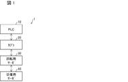
- FIG. 1 is a block diagram showing an outline of a screw tightening system 1 according to the present embodiment.
- a screw tightening system 1 includes a PLC (Programmable Logic Controller) 10 (screw length determination system), a coupler 20, a rotation servo 30 (first motor), and a reciprocating servo 40 (second motor, (Axial position detector)).
- the screw tightening system 1 performs a screw tightening operation by a driver 51 (see FIG. 2) described later, which rotates about an axis and reciprocates in the axial direction.
- the PLC 10 controls the screw tightening operation and determines whether or not the screw length is correct.
- the screws are not the correct length, they may be bottomed (the screw tightening operation may stop halfway because the screw is longer than the screw hole or foreign matter has accumulated in the screw hole) or the screw may not fit in the screw hole. Insufficient screw tightening occurs, such as a short screwing length.
- the screw tightening failure refers to a state in which the screw does not exhibit a sufficient fastening force even when a prescribed torque is applied to the screw.
- the PLC 10 determines the length of the screw to suppress the occurrence of the above-described screw tightening failure.
- the rotation servo 30 is a motor that causes the driver 51 to rotate about its axis. Further, the rotation servo 30 outputs its own rotation speed (deg./s), rotation amount (deg.), And rotation torque (ratio (%) to rated torque) to the coupler 20.
- the reciprocating servo 40 is a motor that causes the driver 51 to reciprocate in the axial direction. Further, the reciprocating servo 40 outputs the moving speed (mm / s), the moving position (mm), and the moving torque (ratio (%) to the rated torque) of the driver 51 due to its own rotation to the coupler 20. Therefore, the reciprocating servo 40 also functions as an axial position detector that detects the axial position of the driver 51.
- the coupler 20 connects the PLC 10 to the rotation servo 30 and the reciprocating servo 40. Specifically, the coupler 20 transmits the control signal received from the PLC 10 to the rotation servo 30 and the reciprocating servo 40. Further, the coupler 20 transmits the rotation speed, the rotation amount, and the rotation torque of the rotation servo 30 received from the rotation servo 30 to the PLC 10. Further, the coupler 20 transmits to the PLC 10 the moving speed, the moving position, and the moving torque of the driver 51, which are received from the reciprocating servo 40 and are rotated by the reciprocating servo 40.
- the rotation speed, rotation amount, and rotation torque of the rotation servo 30, and the movement speed, movement position, and movement torque of the driver 51 due to the rotation of the reciprocating servo 40 may be collectively referred to as parameters.
- FIG. 2 is a block diagram showing the configuration of the PLC 10.
- the PLC 10 controls the operation of the screw tightening system 1.
- the PLC 10 includes a control unit 11, a communication unit 12, and a determination unit 13 (speed measurement unit, length determination unit).
- the control unit 11 outputs a control signal for controlling the rotation servo 30 and the reciprocating servo 40 to the communication unit 12.
- the communication unit 12 transmits the control signal input from the control unit 11 to the coupler 20.
- the control signal is transmitted to the rotating servo 30 and the reciprocating servo 40 via the coupler 20, and controls the rotating servo 30 and the reciprocating servo 40.
- the control unit 11 controls the rotation servo 30 and the reciprocating servo 40 in synchronization with each other. Further, the control unit 11 feeds back the parameters of the rotation servo 30 and the reciprocating servo 40 to the control of the rotation servo 30 and the reciprocating servo 40.
- the communication unit 12 receives parameters from the rotation servo 30 and the reciprocating servo 40 via the coupler 20.
- the communication unit 12 stores the received parameters in a storage device (not shown).
- the screw tightening system 1 may include a storage device for storing the received parameters.
- the control unit 11 and the determination unit 13 acquire parameters from the storage device as needed. Note that, for simplicity, the communication unit 12 outputs the parameters to the control unit 11 and the determination unit 13 in FIG.
- the determination unit 13 determines the screw length based on the parameters in the screw tightening process. A specific example of the determination by the determination unit 13 will be described later.
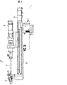
- FIG. 3 is a diagram showing an example of the external appearance of the screw tightening system 1 according to the present embodiment.
- the screw tightening system 1 includes a rotation servo 30, a reciprocating servo 40, a driver unit 50, and a support 60.
- the screw tightening system 1 also includes the PLC 10 and the coupler 20 as described above.
- the driver unit 50 is a unit that tightens screws.
- the driver unit 50 includes a driver 51 and a screw holding portion 52.
- the driver 51 performs the screw tightening operation by reciprocating in the axial direction while rotating about the axis.
- the direction in which the driver 51 moves during the screw tightening process is referred to as the downward direction.
- the rotation servo 30 is arranged above the driver 51, and causes the driver 51 to rotate about its axis. Further, the screw holding portion 52 is provided below the driver 51 and holds a screw to be screwed by the driver 51.
- the column 60 supports the driver unit 50 so that it can move up and down.
- the reciprocating servo 40 is provided on the upper portion of the column 60 and is connected to the driver unit 50 via a ball screw (not shown). The rotary motion of the reciprocating servo 40 is converted into a vertical motion by the ball screw. As a result, the driver unit 50 reciprocates up and down.
- the screw tightening operation by the screw tightening system 1 is as follows. First, the screw holding portion 52, which holds the screw, lowers the screw to a place where the screw is tightened on a workpiece (object to be fastened) (not shown) that is the target of tightening the screw.
- the determination unit 13 sets the time when the tip of the screw comes into contact with the work as the time when the descent ends. Next, the driver 51 presses the screw while rotating it until the screw is temporarily seated.
- the temporary seat refers to a state in which the seat surface of the screw is in contact with the work. In the present embodiment, the state where the rotation torque of the rotation servo 30 reaches 50% (first predetermined value) is the state where the screw is temporarily seated.
- the determination unit 13 sets the time when the rotation torque of the rotation servo 30 reaches the first predetermined value as the time when the screw is temporarily seated.
- the screw tightening system 1 performs the final tightening by pressing the work from the state where the screw is temporarily seated while further rotating the screw.
- the final tightening is performed until the rotation torque of the rotation servo 30 reaches 150% (second predetermined value).
- the screw tightening system 1 sets the moving torque of the reciprocating servo 40 to a predetermined value (third predetermined value). That is, the determination unit 13 is performing final tightening during a period in which the rotation torque of the rotation servo 30 is equal to or more than the first predetermined value and less than the second predetermined value, and the movement torque of the reciprocating servo 40 is the third predetermined value. And the period.
- the screw tightening system 1 stops pressing the screw against the work and maintains the state where the rotation torque is 150% or more for 100 ms.
- the screw tightening operation is completed by moving the driver 51 upward and returning it to the original position.
- the above-mentioned first to third predetermined values and the holding time are examples, and they differ depending on the type of screw and the type of fastening object / fastened object.
- the screw tightening is performed on the work piece in which the female screw is previously cut (tap) at the place where the screw tightening is performed.
- the screw tightening system 1 can also perform screw tightening on a workpiece in a state where a female screw is not cut at a position where screw tightening is performed (tapping (self-tapping)).
- the determination unit 13 sets the state where the rotation torque of the rotation servo 30 reaches 100% as the state where the screw is temporarily seated.
- the determination unit 13 may use another value as the rotation torque of the rotation servo 30 that causes the screw to be temporarily seated when the screw is tightened on the tapping work.
- the determination unit 13 determines which of the end time of the temporary seating, the end time of the period during final fastening, and the end time of the period during final fastening, from the time when the screw descends.
- the length of the screw is determined based on the axial position or the amount of rotation of the driver 51 in the period up to that point.
- the determination by the determination unit 13 in the present embodiment is one of the following (1) and (2).
- the length of the screw is determined based on the change in the position of the driver 51 in the axial direction during the period from the time when the screw descends to the time when the temporary seat is seated or the time when the screw is fully tightened (2) ) The length of the screw is determined based on the rotation amount of the driver 51 in the period from the end time of the screw descending to the end time of the period during final fastening or the end time of the period during final fastening. The determination of the screw length by the determination unit 13 will be described.
- the determining unit 13 may determine the length of the screw based on the average value or the maximum value of the axial position of the driver 51 in the period from the time when the screw ends to descend to the time when the screw is temporarily seated.
- FIG. 4 is a graph showing the position of the driver 51 in the axial direction with respect to time during the period from the time when the screw ends to descend to the time when the screw is temporarily seated, where (a) is the average position and (b) is the position. Indicates the maximum value of.
- the horizontal axis represents time and the vertical axis represents the average value of the position of the driver 51 in the axial direction.
- the horizontal axis represents time and the vertical axis represents the maximum value of the position of the driver 51 in the axial direction.
- the graphs shown in (a) and (b) of FIG. 4 are divided into two regions T1 and T2 in the horizontal axis direction.
- Four changes in the position of the driver 51 when tightening the M4L8 screw are shown in the region T1.
- the area T2 three changes in the position of the driver 51 when the M4L10 screw is tightened are shown.
- the second graph in the area T2 of FIGS. 4A and 4B has a different color from those of the first and third graphs in the area T2 in order to distinguish the graph. It is shown.
- the average value and the maximum value of the position of the driver 51 in the period from the time of the end of the descending of the screw to the time of the temporary seat are set.
- the average value of the position of the driver 51 changes in the range less than the threshold value TH in the screw tightening process of the M4L8 screw, whereas it mainly changes in the screw tightening process of the M4L10 screw. It changes within the range of the threshold value TH or more. Therefore, for example, the threshold value can be set to the average value or the maximum value of the position of the driver 51 in the above period.
- the determination unit 13 can determine the screw length with high accuracy by determining the screw length based on the threshold value.
- the determination unit 13 determines the length of the screw based on, for example, the average value or the minimum value of the axial position of the driver 51 in the period from the end time of the screw descending to the end time of the period during the final tightening of the screw. You may.
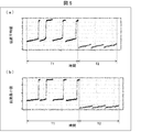
- FIG. 5 is a graph showing the position of the driver 51 in the axial direction with respect to time during the period from the time when the screw descends to the time when the screw is fully tightened, where (a) is the average value of the positions. , (B) show the minimum value of the position.
- the horizontal axis represents time and the vertical axis represents the average value of the position of the driver 51 in the axial direction.
- the horizontal axis represents time and the vertical axis represents the minimum value of the position of the driver 51 in the axial direction.
- the graphs shown in (a) and (b) of FIG. 5 are also divided into regions T1 and T2 similar to the graphs shown in (a) and (b) of FIG. 4 in the horizontal axis direction.
- a threshold value can be set for the change amount of the average value or the minimum value of the position of the driver 51 in the above period.
- the determination unit 13 can determine the screw length with high accuracy by determining the screw length based on the threshold value.
- the determination unit 13 may determine the screw length based on the maximum value of the rotation amount of the driver 51 in the period from the time when the screw descends to the time when the screw is fully tightened.
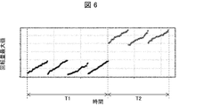
- FIG. 6 is a graph showing the maximum value of the rotation amount of the driver 51 with respect to time in the period from the time when the screw descends to the time when the screw is fully tightened.
- the horizontal axis represents time and the vertical axis represents the maximum value of the rotation amount of the driver 51.
- the graphs shown in (a) and (b) of FIG. 5 are also divided into regions T1 and T2 similar to the graphs shown in (a) and (b) of FIG. 4 in the horizontal axis direction.
- a threshold value can be set for the maximum value of the rotation amount of the driver 51 in the above period.
- the determination unit 13 can determine the screw length with high accuracy by determining the screw length based on the threshold value.
- the determination unit 13 determines, for example, the length of the screw based on the average value, the maximum value, or the minimum value of the rotation amount of the driver 51 in the period from the end time of the screw descending to the end time of the period during which the screw is being fully tightened and held. May be determined.
- FIG. 7 is a graph showing the amount of rotation of the driver 51 with respect to time during the period from the end time of the screw descent to the end time of the period during which the screw is fully tightened and held, and (a) is the average value of the rotation amount. , (B) shows the maximum value of the rotation amount, and (c) shows the minimum value of the rotation amount.
- the horizontal axis represents time and the vertical axis represents the average value of the rotation amount of the driver 51.
- the horizontal axis represents time and the vertical axis represents the maximum value of the rotation amount of the driver 51.
- the horizontal axis represents time and the vertical axis represents the minimum value of the rotation amount of the driver 51.
- the graphs shown in (a) to (c) of FIG. 7 are also divided into regions T1 and T2 similar to the graphs shown in (a) and (b) of FIG. 4 in the horizontal axis direction.
- the threshold value can be set to the average value, the maximum value, or the minimum value of the rotation amount of the driver 51 in the above period.
- the determination unit 13 can determine the screw length with high accuracy by determining the screw length based on the threshold value.
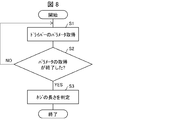
- FIG. 8 is a flowchart showing an example of processing in the determination unit 13.
- the determination unit 13 acquires a parameter used to determine the screw length from the rotation servo 30 or the reciprocating servo 40 (S1). For example, if the determination described in 3.1 is performed, the determination unit 13 acquires the position information of the driver 51 in the axial direction from the reciprocating servo 40 and calculates the average value thereof.
- the determination unit 13 determines whether the period for acquiring the parameters has ended (S2). For example, if the determination described in 3.1 is performed, the determination unit 13 determines whether the screw is temporarily seated. When the period for acquiring the parameters has not ended (NO in S2), the determination unit 13 repeats the processing from step S1.
- the determination unit 13 determines the length of the screw (S3). Then, the determination unit 13 ends the process.
- the PLC 10 can determine the screw length with high accuracy by performing any of the determinations of 3.1 to 3.4 described above. In particular, when any one of the above 3.1 to 3.3 is determined, the PLC 10 can determine the screw length before the period during which the main tightening and holding is completed, so that the screw length can be determined early. Can be determined.
- the PLC 10 may further include a notification unit that notifies the screw length determined by the determination unit 13 in step S3.
- the notification unit may notify the user of the screw tightening system 1 by voice, light, or image.
- the screw tightening system 1 may include a speaker, a light emitting device, an image display device, or the like for the notification unit to notify.
- the determination unit 13 both measures the moving speed of the driver 51 and calculates the screw length, but they may be executed by different processing units.
- the PLC 10 controls both the screw tightening operation and the screw length, but the PLC for performing the above control and the PLC for performing the above determination may be provided separately.
- one screw length determination controller may receive measurement data from a plurality of screw tightening control PLCs and determine the screw length.
- the screw length determination controller corresponds to the screw length determination system.
- FIG. 9 is a diagram illustrating an example of a table referred to by the determination unit 13.
- the judgment unit 13 shows the relationship between the screw length and the position of the driver 51 in the axial direction.
- the length of the screw may be determined by referring to the table.
- FIG. 9 shows a table showing the relationship between the average value of the position of the driver 51 in the axial direction and the screw length in the case of determining the screw whose graph is shown in FIG.
- the determination unit 13 By determining the length of the screw by referring to such a table, the determination unit 13 reduces the influence of the variation of the position of the driver 51 in the screw tightening process due to the individual difference of the screw on the determination. it can.
- the above table may be stored in a storage device (not shown) connected to the PLC 10 via the coupler 20, for example.
- control block of the screw tightening system 1 may be realized by a logic circuit (hardware) formed in an integrated circuit (IC chip) or the like. However, it may be realized by software.
- the screw tightening system 1 is equipped with a computer that executes the instructions of a program that is software that realizes each function.
- the computer includes, for example, one or more processors and a computer-readable recording medium that stores the program. Then, in the computer, the processor reads the program from the recording medium and executes the program to achieve the object of the present invention.
- the processor for example, a CPU (Central Processing Unit) can be used.
- the recording medium a "non-transitory tangible medium" such as a ROM (Read Only Memory), a tape, a disk, a card, a semiconductor memory, a programmable logic circuit, or the like can be used.
- a RAM Random Access Memory
- the program may be supplied to the computer via any transmission medium (communication network, broadcast wave, etc.) capable of transmitting the program.
- any transmission medium communication network, broadcast wave, etc.
- one aspect of the present invention can also be realized in the form of a data signal embedded in a carrier wave, in which the program is embodied by electronic transmission.
- the time when the tip of the screw comes into contact with the object to be tightened is the end time of the descent, and the seat surface of the screw is the object to be covered.
- the time of contact with the fastener is the time of temporary seating, and the rotational torque of the first motor that causes rotational movement around the axis of the driver for tightening the screw is greater than or equal to the first predetermined value
- Rotation around the axis of the driver is defined as a period during the final tightening, which is less than a predetermined value and the moving torque of the second motor that causes the driver to reciprocate in the axial direction is the third predetermined value.
- the main torque is maintained for a period in which the rotational torque of the first motor that causes the motion is the second predetermined value and the moving torque of the second motor that causes the driver to reciprocate in the axial direction is the third predetermined value.
- the length of the screw is determined based on the position or the amount of rotation in the axial direction.
- the screw length determination system uses the screw position based on the axial position or the amount of rotation of the screwdriver as a starting point from the time when the screw descends and ends until the predetermined screw tightening process ends. Determine the length of. Therefore, the length of the screw can be determined with higher accuracy as compared with the case where the length of the screw is determined based on, for example, the time required for screw tightening.
- the screw length determination system determines the position in the axial direction of the driver in the period from the time of the end of the descent to the time of the temporary seat or the end time of the period during the final tightening.
- the length of the screw is determined based on the change.
- a screw length determination system is based on an average value or a maximum value of the axial position of the driver in a period from the time of the end of the descent to the time of the temporary seating. Determine the length.
- the screw length determination system is based on an average value or a minimum value of axial positions of the driver in a period from the end of the descent to the end time of the period during the final tightening. Determine the screw length.
- the screw length determination system determines the length of the screw by referring to a table showing the relationship between the length of the screw and the position of the driver in the axial direction.
- the difference between the screw position, the difference in the screwdriver position, the difference in the screw length, and the difference in the height of the work caused by the individual difference in the screw cause a difference between the screw and the work. It is possible to reduce the influence of the variation in the relative position of the above on the determination.
- the screw length determination system according to an aspect of the present invention, the screw length determination system of the driver in the period from the time of the end of the descent to the end time of the period during the main fastening or the end time of the period during the main fastening holding.
- the length of the screw is determined based on the rotation amount.
- the screw length determination system is configured such that the screw length is determined based on a maximum value of the rotation amount of the driver in a period from the time of the end of the descent to the end time of the period during the final tightening.
- the screw length determination system is an average value, a maximum value or a minimum value of the rotation amount of the driver in a period from the time of the end of the descent to the end time of the period during the final tightening holding.
- the length of the screw is determined based on.
- a screw tightening system includes a rotation servo that causes a rotational movement of a driver around an axis, a reciprocating servo that causes a reciprocating movement of the driver in an axial direction, and An axial position detector that detects a position in the axial direction, and the screw length determination system according to any one of the above aspects are provided.
- the screw length determination system uses the position of the driver detected by the axial position detection unit.
- the screw length can be determined based on the rotation amount of the driver acquired from the rotation servo.
- a program according to one aspect of the present invention causes a computer to operate as the screw tightening failure determination device according to any one of the above aspects.
Landscapes
- Engineering & Computer Science (AREA)
- Physics & Mathematics (AREA)
- General Physics & Mathematics (AREA)
- Mechanical Engineering (AREA)
- Human Computer Interaction (AREA)
- Manufacturing & Machinery (AREA)
- Automation & Control Theory (AREA)
- Details Of Spanners, Wrenches, And Screw Drivers And Accessories (AREA)
Abstract
L'invention concerne un système de détermination de longueur de vis capable de déterminer la longueur d'une vis avec un degré élevé de précision. Un PLC (10) détermine la longueur d'une vis sur la base de la quantité de rotation ou de la position dans la direction axiale d'un tournevis pendant une période prolongée à partir du moment où la vis achève sa descente jusqu'à ce qu'un moment quelconque parmi le moment où se produit un siège provisoire, le moment où la période de serrage primaire prend fin et le moment où la période de maintien du serrage primaire prend fin.
Priority Applications (4)
| Application Number | Priority Date | Filing Date | Title |
|---|---|---|---|
| KR1020217007443A KR102543200B1 (ko) | 2018-10-29 | 2019-09-25 | 나사 길이 판정 시스템, 나사 조임 시스템 및 매체 |
| CN201980058616.5A CN112654458B (zh) | 2018-10-29 | 2019-09-25 | 螺丝长度判定系统、螺丝拧紧系统以及存储介质 |
| EP19880766.1A EP3875213B1 (fr) | 2018-10-29 | 2019-09-25 | Système de détermination de longueur de vis, système de serrage de vis et programme |
| US17/278,666 US11453091B2 (en) | 2018-10-29 | 2019-09-25 | Screw length determination system, screw-tightening system and storage medium |
Applications Claiming Priority (2)
| Application Number | Priority Date | Filing Date | Title |
|---|---|---|---|
| JP2018203046A JP7031558B2 (ja) | 2018-10-29 | 2018-10-29 | ネジ長判定システム、ネジ締めシステムおよびプログラム |
| JP2018-203046 | 2018-10-29 |
Publications (1)
| Publication Number | Publication Date |
|---|---|
| WO2020090301A1 true WO2020090301A1 (fr) | 2020-05-07 |
Family
ID=70463426
Family Applications (1)
| Application Number | Title | Priority Date | Filing Date |
|---|---|---|---|
| PCT/JP2019/037679 Ceased WO2020090301A1 (fr) | 2018-10-29 | 2019-09-25 | Système de détermination de longueur de vis, système de serrage de vis et programme |
Country Status (6)
| Country | Link |
|---|---|
| US (1) | US11453091B2 (fr) |
| EP (1) | EP3875213B1 (fr) |
| JP (1) | JP7031558B2 (fr) |
| KR (1) | KR102543200B1 (fr) |
| CN (1) | CN112654458B (fr) |
| WO (1) | WO2020090301A1 (fr) |
Families Citing this family (1)
| Publication number | Priority date | Publication date | Assignee | Title |
|---|---|---|---|---|
| SE2330239A1 (en) * | 2023-05-26 | 2024-11-19 | Atlas Copco Ind Technique Ab | System for measuring distance between tightening tool and work piece surface |
Citations (6)
| Publication number | Priority date | Publication date | Assignee | Title |
|---|---|---|---|---|
| JPH0263932U (fr) * | 1988-10-31 | 1990-05-14 | ||
| JPH06262453A (ja) * | 1993-01-13 | 1994-09-20 | Nippondenso Co Ltd | ねじ締め装置 |
| JPH07164261A (ja) | 1993-12-10 | 1995-06-27 | Mazda Motor Corp | ボルトの締付異常検出方法および検出装置 |
| JPH07280677A (ja) * | 1994-04-05 | 1995-10-27 | Toyota Motor Corp | ボルト軸力測定方法および装置 |
| JP2012223841A (ja) * | 2011-04-15 | 2012-11-15 | Nitto Seiko Co Ltd | 自動ねじ締め装置 |
| KR20160054200A (ko) * | 2014-11-06 | 2016-05-16 | 문희정 | 볼트의 체결력을 보정할 수 있는 기능성 너트 러너 |
Family Cites Families (8)
| Publication number | Priority date | Publication date | Assignee | Title |
|---|---|---|---|---|
| US4530143A (en) * | 1983-05-04 | 1985-07-23 | Casarcia Dominick A | Ultrasonic bolt tensioner |
| JPH0263932A (ja) | 1988-08-30 | 1990-03-05 | Mitsubishi Electric Corp | オートマチツク車のシフトロツク装置 |
| JPH06170663A (ja) * | 1992-12-04 | 1994-06-21 | Matsushita Electric Ind Co Ltd | 螺子締め方法 |
| JPH09285921A (ja) * | 1996-04-22 | 1997-11-04 | Matsushita Electric Ind Co Ltd | 産業用ねじ締めロボットにおけるねじ締め方法 |
| DE10042291C1 (de) * | 2000-08-29 | 2002-02-14 | Fraunhofer Ges Forschung | Verfahren zur Überwachung und Steuerung eines Schraubvorganges |
| JP5797967B2 (ja) * | 2011-07-30 | 2015-10-21 | 日東精工株式会社 | 自動ねじ締め装置 |
| JP5824354B2 (ja) * | 2011-12-23 | 2015-11-25 | 日東精工株式会社 | 自動ねじ締め装置 |
| CN106493552A (zh) * | 2016-10-20 | 2017-03-15 | 珠海格力电器股份有限公司 | 一种螺钉自动拧紧装置及其扭矩测试方法 |
-
2018
- 2018-10-29 JP JP2018203046A patent/JP7031558B2/ja active Active
-
2019
- 2019-09-25 KR KR1020217007443A patent/KR102543200B1/ko active Active
- 2019-09-25 WO PCT/JP2019/037679 patent/WO2020090301A1/fr not_active Ceased
- 2019-09-25 EP EP19880766.1A patent/EP3875213B1/fr active Active
- 2019-09-25 CN CN201980058616.5A patent/CN112654458B/zh active Active
- 2019-09-25 US US17/278,666 patent/US11453091B2/en active Active
Patent Citations (6)
| Publication number | Priority date | Publication date | Assignee | Title |
|---|---|---|---|---|
| JPH0263932U (fr) * | 1988-10-31 | 1990-05-14 | ||
| JPH06262453A (ja) * | 1993-01-13 | 1994-09-20 | Nippondenso Co Ltd | ねじ締め装置 |
| JPH07164261A (ja) | 1993-12-10 | 1995-06-27 | Mazda Motor Corp | ボルトの締付異常検出方法および検出装置 |
| JPH07280677A (ja) * | 1994-04-05 | 1995-10-27 | Toyota Motor Corp | ボルト軸力測定方法および装置 |
| JP2012223841A (ja) * | 2011-04-15 | 2012-11-15 | Nitto Seiko Co Ltd | 自動ねじ締め装置 |
| KR20160054200A (ko) * | 2014-11-06 | 2016-05-16 | 문희정 | 볼트의 체결력을 보정할 수 있는 기능성 너트 러너 |
Non-Patent Citations (1)
| Title |
|---|
| See also references of EP3875213A4 |
Also Published As
| Publication number | Publication date |
|---|---|
| US11453091B2 (en) | 2022-09-27 |
| JP2020069543A (ja) | 2020-05-07 |
| EP3875213B1 (fr) | 2024-03-13 |
| US20220040805A1 (en) | 2022-02-10 |
| CN112654458B (zh) | 2022-11-11 |
| EP3875213A4 (fr) | 2022-07-27 |
| EP3875213A1 (fr) | 2021-09-08 |
| KR102543200B1 (ko) | 2023-06-13 |
| JP7031558B2 (ja) | 2022-03-08 |
| CN112654458A (zh) | 2021-04-13 |
| KR20210042973A (ko) | 2021-04-20 |
Similar Documents
| Publication | Publication Date | Title |
|---|---|---|
| JP7035859B2 (ja) | ネジ締め不良判定装置、ネジ締めシステムおよびプログラム | |
| WO2020090292A1 (fr) | Système de détermination de longueur de vis, système de serrage de vis et programme | |
| WO2020090301A1 (fr) | Système de détermination de longueur de vis, système de serrage de vis et programme | |
| JP7070467B2 (ja) | ねじ締め不良判定装置、ねじ締め装置、ねじ締め不良判定方法、および制御プログラム | |
| US20230271282A1 (en) | Screw tightening system, controller, and non-transitory storage medium | |
| US11964351B2 (en) | Screw fastening failure determination device, screw fastening device, screw fastening failure determination method, and non-transitory computer readable medium | |
| WO2021235041A1 (fr) | Dispositif de détermination de défaut de vissage | |
| JP7070164B2 (ja) | ネジ締め不良判定装置、ネジ締めシステムおよびプログラム | |
| US11759956B2 (en) | Robot system and control method for robot system | |
| JP2020163557A (ja) | ねじ締め不良判定装置、ねじ締め装置、ねじ締め不良判定方法、および制御プログラム | |
| JP2020163500A (ja) | ネジ締付装置の異常検知方法 |
Legal Events
| Date | Code | Title | Description |
|---|---|---|---|
| 121 | Ep: the epo has been informed by wipo that ep was designated in this application |
Ref document number: 19880766 Country of ref document: EP Kind code of ref document: A1 |
|
| ENP | Entry into the national phase |
Ref document number: 20217007443 Country of ref document: KR Kind code of ref document: A |
|
| NENP | Non-entry into the national phase |
Ref country code: DE |
|
| ENP | Entry into the national phase |
Ref document number: 2019880766 Country of ref document: EP Effective date: 20210531 |