WO2020090323A1 - Système de transporteur - Google Patents
Système de transporteur Download PDFInfo
- Publication number
- WO2020090323A1 WO2020090323A1 PCT/JP2019/038627 JP2019038627W WO2020090323A1 WO 2020090323 A1 WO2020090323 A1 WO 2020090323A1 JP 2019038627 W JP2019038627 W JP 2019038627W WO 2020090323 A1 WO2020090323 A1 WO 2020090323A1
- Authority
- WO
- WIPO (PCT)
- Prior art keywords
- conveyor
- line
- article
- backup
- unit
- Prior art date
- Legal status (The legal status is an assumption and is not a legal conclusion. Google has not performed a legal analysis and makes no representation as to the accuracy of the status listed.)
- Ceased
Links
Images


Classifications
-
- B—PERFORMING OPERATIONS; TRANSPORTING
- B65—CONVEYING; PACKING; STORING; HANDLING THIN OR FILAMENTARY MATERIAL
- B65G—TRANSPORT OR STORAGE DEVICES, e.g. CONVEYORS FOR LOADING OR TIPPING, SHOP CONVEYOR SYSTEMS OR PNEUMATIC TUBE CONVEYORS
- B65G15/00—Conveyors having endless load-conveying surfaces, i.e. belts and like continuous members, to which tractive effort is transmitted by means other than endless driving elements of similar configuration
- B65G15/06—Conveyors having endless load-conveying surfaces, i.e. belts and like continuous members, to which tractive effort is transmitted by means other than endless driving elements of similar configuration with oppositely-moving parts of the endless surface located in the same plane and parallel to one another
-
- B—PERFORMING OPERATIONS; TRANSPORTING
- B65—CONVEYING; PACKING; STORING; HANDLING THIN OR FILAMENTARY MATERIAL
- B65G—TRANSPORT OR STORAGE DEVICES, e.g. CONVEYORS FOR LOADING OR TIPPING, SHOP CONVEYOR SYSTEMS OR PNEUMATIC TUBE CONVEYORS
- B65G37/00—Combinations of mechanical conveyors of the same kind, or of different kinds, of interest apart from their application in particular machines or use in particular manufacturing processes
- B65G37/02—Flow-sheets for conveyor combinations in warehouses, magazines or workshops
-
- B—PERFORMING OPERATIONS; TRANSPORTING
- B65—CONVEYING; PACKING; STORING; HANDLING THIN OR FILAMENTARY MATERIAL
- B65G—TRANSPORT OR STORAGE DEVICES, e.g. CONVEYORS FOR LOADING OR TIPPING, SHOP CONVEYOR SYSTEMS OR PNEUMATIC TUBE CONVEYORS
- B65G43/00—Control devices, e.g. for safety, warning or fault-correcting
- B65G43/02—Control devices, e.g. for safety, warning or fault-correcting detecting dangerous physical condition of load carriers, e.g. for interrupting the drive in the event of overheating
-
- B—PERFORMING OPERATIONS; TRANSPORTING
- B65—CONVEYING; PACKING; STORING; HANDLING THIN OR FILAMENTARY MATERIAL
- B65G—TRANSPORT OR STORAGE DEVICES, e.g. CONVEYORS FOR LOADING OR TIPPING, SHOP CONVEYOR SYSTEMS OR PNEUMATIC TUBE CONVEYORS
- B65G47/00—Article or material-handling devices associated with conveyors; Methods employing such devices
- B65G47/52—Devices for transferring articles or materials between conveyors i.e. discharging or feeding devices
- B65G47/53—Devices for transferring articles or materials between conveyors i.e. discharging or feeding devices between conveyors which cross one another
-
- H—ELECTRICITY
- H10—SEMICONDUCTOR DEVICES; ELECTRIC SOLID-STATE DEVICES NOT OTHERWISE PROVIDED FOR
- H10P—GENERIC PROCESSES OR APPARATUS FOR THE MANUFACTURE OR TREATMENT OF DEVICES COVERED BY CLASS H10
- H10P72/00—Handling or holding of wafers, substrates or devices during manufacture or treatment thereof
- H10P72/30—Handling or holding of wafers, substrates or devices during manufacture or treatment thereof for conveying, e.g. between different workstations
- H10P72/32—Handling or holding of wafers, substrates or devices during manufacture or treatment thereof for conveying, e.g. between different workstations between different workstations
- H10P72/3208—Changing the direction of the conveying path
-
- H—ELECTRICITY
- H10—SEMICONDUCTOR DEVICES; ELECTRIC SOLID-STATE DEVICES NOT OTHERWISE PROVIDED FOR
- H10P—GENERIC PROCESSES OR APPARATUS FOR THE MANUFACTURE OR TREATMENT OF DEVICES COVERED BY CLASS H10
- H10P72/00—Handling or holding of wafers, substrates or devices during manufacture or treatment thereof
- H10P72/30—Handling or holding of wafers, substrates or devices during manufacture or treatment thereof for conveying, e.g. between different workstations
- H10P72/32—Handling or holding of wafers, substrates or devices during manufacture or treatment thereof for conveying, e.g. between different workstations between different workstations
- H10P72/3216—Handling or holding of wafers, substrates or devices during manufacture or treatment thereof for conveying, e.g. between different workstations between different workstations using a general scheme of a conveying path within a factory
-
- B—PERFORMING OPERATIONS; TRANSPORTING
- B65—CONVEYING; PACKING; STORING; HANDLING THIN OR FILAMENTARY MATERIAL
- B65G—TRANSPORT OR STORAGE DEVICES, e.g. CONVEYORS FOR LOADING OR TIPPING, SHOP CONVEYOR SYSTEMS OR PNEUMATIC TUBE CONVEYORS
- B65G2201/00—Indexing codes relating to handling devices, e.g. conveyors, characterised by the type of product or load being conveyed or handled
- B65G2201/02—Articles
- B65G2201/0297—Wafer cassette
-
- B—PERFORMING OPERATIONS; TRANSPORTING
- B65—CONVEYING; PACKING; STORING; HANDLING THIN OR FILAMENTARY MATERIAL
- B65G—TRANSPORT OR STORAGE DEVICES, e.g. CONVEYORS FOR LOADING OR TIPPING, SHOP CONVEYOR SYSTEMS OR PNEUMATIC TUBE CONVEYORS
- B65G2203/00—Indexing code relating to control or detection of the articles or the load carriers during conveying
- B65G2203/02—Control or detection
- B65G2203/0266—Control or detection relating to the load carrier(s)
-
- B—PERFORMING OPERATIONS; TRANSPORTING
- B65—CONVEYING; PACKING; STORING; HANDLING THIN OR FILAMENTARY MATERIAL
- B65G—TRANSPORT OR STORAGE DEVICES, e.g. CONVEYORS FOR LOADING OR TIPPING, SHOP CONVEYOR SYSTEMS OR PNEUMATIC TUBE CONVEYORS
- B65G2207/00—Indexing codes relating to constructional details, configuration and additional features of a handling device, e.g. Conveyors
- B65G2207/14—Combination of conveyors
Definitions
- One aspect of the present invention relates to a conveyor system.
- Patent Document 1 discloses a conveyor system in which two conveyor lines that convey articles in opposite directions along one direction are arranged in parallel in the width direction of a belt conveyor.
- a conveyor system for example, there is a case where it is desired to provide a backup line that can replace the transportation of articles when the conveyor line is out of order or when maintenance is performed (hereinafter, these are collectively referred to as “abnormality of the conveyor line”). ..
- an object of one aspect of the present invention is to provide a conveyor system capable of compactly constructing a backup line that substitutes for the transportation of articles when an abnormality occurs in the conveyor line.
- a conveyor system is a conveyor system including a conveyor device that supports and conveys a bottom portion of an article, the first conveyor line conveying the article in a first direction, and A second conveyor line, which is provided in parallel with the conveyor line and conveys the article in a second direction opposite to the first direction, and is provided in parallel with the first conveyor line and the second conveyor line, A backup line provided to be able to switch between a state in which the article is conveyed in the first direction and a state in which the article is conveyed in the second direction, and a plurality of first connections for conveying the article between the first conveyor line and the backup line A line and a plurality of second connection lines for conveying articles between the second conveyor line and the backup line.
- backup lines corresponding to the first conveyor line and the second conveyor line are not provided, but only one backup line is provided for the first conveyor line and the second conveyor line. Has been. And this one backup line is configured to be able to convey articles in both the first direction and the second direction, and between the one backup line and both the first conveyor line and the second conveyor line.
- a first connection line and a second connection line that can carry in and carry out articles are provided. Accordingly, the same function as the configuration in which the backup lines are provided on the first conveyor line and the second conveyor line can be configured by one backup line. As a result, it is possible to construct a compact backup line that substitutes for the conveyance of articles when an abnormality occurs in the conveyor line.
- a conveyor system includes a control unit that controls a conveyor device that configures each of a first conveyor line, a second conveyor line, a backup line, a first connection line, and a second connection line;
- An abnormal state acquisition unit that acquires an abnormality in at least one of the conveyor devices that form each of the conveyor line and the second conveyor line, and the control unit may have an abnormality in the abnormal state acquisition unit.
- the article is transported so as to avoid the abnormal portion by using the backup line, the first connection line, and the second connection line which are activated at the time of abnormality.
- the backup line the first connection line
- the second connection line which are activated at the time of abnormality.
- a swivel conveyor device for supporting and conveying the bottom of the article and rotating the article about the vertical axis as a conveyor device at each of the connection portions of the backup line and the second connection line.
- control unit is arranged on each of the two connecting portions when the article is located on the conveyor device arranged between the two connecting portions adjacent to each other.
- the rotation of the swivel conveyor may be prohibited. According to this configuration, it is possible to prevent the articles from colliding with each other during the backup control.
- the control unit searches for the shortest route for avoiding the abnormal conveyor device, and selects only the conveyor device corresponding to the shortest route among the conveyor devices that form the backup line. You may start it.
- this configuration it is possible to minimize the number of conveyor devices activated as backup lines.
- the distance in the carrying direction of the backup line used for avoiding one abnormal place can be shortened, it is possible to leave a longer distance in the carrying direction for the back line used for avoiding another abnormal place. it can.
- even if abnormalities occur at a plurality of locations it is possible to increase the possibility of avoiding them at the same time.
- the backup line may be provided between the first conveyor line and the second conveyor line in the width direction orthogonal to the first direction. According to this configuration, the configurations of the first connection line and the second connection line can be easily constructed.
- the first connection line and the second connection line are provided so as to be capable of being carried in both directions of carrying in an article to the backup line or carrying out an article from the backup line. May be. According to this configuration, it is possible to select more avoidance routes when executing the backup control. As a result, for example, it becomes possible to avoid an abnormal portion with a shorter route.
- the first conveyor line and the second conveyor line are arranged to face an inter-storey conveyor that conveys articles in a vertical direction, and a storage conveyor of the inter-storey conveyor. May be connected to.
- a space is required to provide the inter-floor transfer device, and the space for providing the conveyor device is often limited.
- the backup line can be constructed compactly, so that the backup line can be constructed even when the inter-floor transfer device is provided.
- the conveyor system according to one aspect of the present invention may be arranged between mutually different buildings, and may connect processing systems arranged respectively inside different buildings. If the conveyor system is arranged between different buildings, the laying distance becomes relatively long and the cost increases. According to this configuration, since it is sufficient to lay one backup line, it is possible to suppress an increase in cost.
- FIG. 1 is a schematic plan view showing a first building, a second building, and an inter-building corridor in which a conveyor system according to an embodiment is arranged.
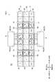
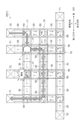
- FIG. 2 is a plan view showing a part of the conveyor system arranged in the first building.
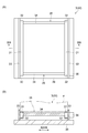
- 3A is a plan view of the first conveyor unit, and FIG. 3B is a sectional view taken along line IIIB-IIIB of FIG. 3A.
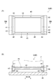
- FIG. 4A is a plan view of the second conveyor unit, and FIG. 4B is a sectional view taken along line IVB-IVB of FIG. 4A.
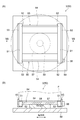
- 5A is a plan view of the swivel conveyor unit, and FIG. 5B is a sectional view taken along line VB-VB of FIG. 5A.
- FIGS. 1 is a schematic plan view showing a first building, a second building, and an inter-building corridor in which a conveyor system according to an embodiment is arranged.
- FIG. 2 is a plan view showing a part of the conveyor system arranged in
- FIG. 6A to 6D is a diagram illustrating an example of backup control when an abnormality occurs in the first conveyor line or the second conveyor line.
- FIGS. 7A to 7D are views for explaining an example of backup control when an abnormality occurs in both the first conveyor line and the second conveyor line.
- FIG. 8 is a plan view showing a part of the conveyor system arranged in the second building.
- FIG. 9 is a plan view showing a part of a conveyor system arranged in an inter-building building.
- FIG. 10 is a plan view showing a part of the conveyor system according to the first modification.
- FIG. 11 is a plan view showing a part of the conveyor system according to the second modification.
- the conveyor system 1 of the present embodiment is arranged in each of a first building B1, a second building B2, and an inter-building building C.
- a plurality of stockers 6 for storing containers hereinafter, referred to as “articles F” (see FIG. 2)
- a processing system including a conveyor system 1A that carries out the article F from the container is constructed.
- the article F includes, for example, a FOUP (Front-Opening Unified Pod) that houses a wafer processed by a semiconductor manufacturing apparatus or a liquid crystal manufacturing apparatus, and a reticle pod that houses a reticle used in the semiconductor manufacturing apparatus or the liquid crystal manufacturing apparatus. Is included. In this embodiment, FOUP will be described as an example.
- FOUP Front-Opening Unified Pod
- a processing device 7 that performs some processing on the wafers contained in the article F, an inter-floor transfer device 8 that vertically moves to transfer the article F to another floor, and an article F
- a processing system including a conveyor system 1B that carries in the processing device 7 or the inter-floor transportation device 8 and carries out the article F from the processing device 7 or the inter-floor transportation device 8 is constructed.
- the processing device 7 include a device that performs various processes such as cleaning, ion implantation, heat treatment, lithography, etching, film formation, and planarization on the wafer.
- Inter-building building C is located between the first building B1 and the second building B2.
- a conveyor system 1C is arranged in the inter-building building C.
- the conveyor system 1C is arranged between the first building B1 and the second building B2 which are different from each other, and connects the processing systems which are respectively arranged inside the different first building B1 and the second building B2.
- the conveyor system 1A arranged in the first building B1 will be described in detail.
- the conveyor system 1A includes a first conveyor unit 30 (see FIGS. 3A and 3B) as a conveyor unit (conveyor device) 3 that supports and conveys the bottom of the article F, and a second conveyor unit 40 ( 4A and FIG. 4B), and a swivel conveyor unit (swivel conveyor device) 50 (see FIG. 5A and FIG. 5B).
- the conveyor system 1A includes a first conveyor line 11, a second conveyor line 13, a backup line 15, a plurality of first connection lines 17, and a plurality of second connection lines 19.
- the article loading / unloading line 21, an abnormal state acquisition unit 80 (see FIG. 1), and a control unit 90 (see FIG. 1) are provided.
- the first conveyor line 11 is a part that conveys the article F in the first direction.
- the first conveyor line 11 includes a first conveyor unit 30 and a swivel conveyor unit 50.
- the first conveyor unit 30 has a pair of belts 31 and 31 that support and convey both widthwise ends of the bottom of the article F.
- the pair of belts 31, 31 are annular endless belts, and each of the belts 31, 31 is wound around a pair of conveyor rollers 35, 35 arranged in the transport direction.
- the conveyor roller 35 has a roller portion 32 around which the belt 31 is wound, and a connecting shaft 34 that connects the roller portions 32, 32 to each other.
- Each of the belts 31 and 31 rotates when at least one of the conveyor rollers 35 and 35 is driven by the drive unit 36, and conveys the article F to be supported in the first direction.
- the pair of conveyor rollers 35, 35 are supported by the guide portion 33.
- the guide portion 33 has a function of supporting the pair of conveyor rollers 35, 35 and guiding the side surface of the article F.
- the guide portion 33 is supported by the base portion 39.
- the swivel conveyor unit 50 has a pair of belts 51, 51 that support and convey both ends in the width direction at the bottom of the article F. ..
- the pair of belts 51, 51 are annular endless belts, and each of the belts 51, 51 is wound around a pair of conveyor rollers 55, 55 arranged in the transport direction.
- the conveyor roller 55 has a roller portion 52 around which the belt 51 is wound, and a connecting shaft 54 that connects the roller portions 52, 52 to each other.
- Each of the belts 51, 51 is rotated by driving at least one of the conveyor rollers 55, 55 by the drive unit 56, and conveys the article F to be supported in the first direction.
- a guide section 53 is provided on the pair of conveyor rollers 55, 55.
- the guide portion 53 has a function of guiding the side surface of the article F.
- the pair of conveyor rollers 55, 55 are supported by the swivel unit 57.
- the revolving unit 57 supports the pair of conveyor rollers 55, 55 and revolves the pair of conveyor rollers 55, 55 to change the traveling direction of the article F.
- the revolving unit 57 is revolved by the drive unit 58 to revolve the pair of conveyor rollers 55, 55 that it supports.
- the swivel portion 57 is supported by the base portion 59. That is, the pair of conveyor rollers 55, 55 supported by the swivel unit 57 are swivelably provided with respect to the base unit 59.
- the swiveling conveyor unit 50 described above is provided as a conveyor device arranged at the connection portion with the line 19 and the connection portion with the backup line 15 and the second connection line 19.
- an article F such as a FOUP whose front-rear direction is fixed can be conveyed while maintaining the front-rear direction.
- the second conveyor line 13 is a portion that is provided parallel to each other in the width direction orthogonal to the first direction and that conveys the article F in the second direction opposite to the first direction. ..
- the second conveyor line 13 includes a first conveyor unit 30 and a swivel conveyor unit 50.
- the first conveyor unit 30 and the swivel conveyor unit 50 used in the second conveyor line 13 are the same as the first conveyor unit 30 and the swivel conveyor unit 50 used in the first conveyor line 11, except that the article F is conveyed in the second direction.
- the configuration of 50 is the same. Therefore, detailed description of the first conveyor unit 30 and the swivel conveyor unit 50 is omitted here.
- the backup line 15 is a part that functions as a backup for the first conveyor line 11 and the second conveyor line 13.
- the backup line 15 is in a stopped state at a normal time when there is no abnormality in all of the first conveyor unit 30 and the swiveling conveyor unit 50 included in the first conveyor line 11 and the second conveyor line 13, and the first conveyor line 11 and the first conveyor line 11
- at the time of abnormality it is used as an avoidance route.
- stopped state here includes both the state where the power is not turned on and the state where the power is turned on but is not operating.
- the backup line 15 is provided parallel to the first conveyor line 11 and the second conveyor line 13, and in the width direction of the first conveyor line 11 and the second conveyor line 13, the first conveyor line 11 and the second conveyor line It is provided between the line 13.
- the backup line 15 is provided so as to be capable of switching between a state in which the article F is conveyed in the first direction and a state in which the article F is conveyed in the second direction.
- the backup line 15 includes a first conveyor unit 30 and a swivel conveyor unit 50.
- the first conveyor unit 30 and the swivel conveyor unit 50 used for the backup line 15 are used for the first conveyor line 11 except that the article F is provided so as to be able to be conveyed in both the first direction and the second direction.
- the configurations of the first conveyor unit 30 and the swivel conveyor unit 50 are the same. Therefore, detailed description of the first conveyor unit 30 and the swivel conveyor unit 50 is omitted here.
- the first connection line 17 is a part that functions as a backup for the first conveyor line 11 and the second conveyor line 13.
- the first connection line 17 conveys the article F between the first conveyor line 11 and the backup line 15.
- the first connection line 17 includes a swivel conveyor unit 50 that constitutes the first conveyor line 11, a swivel conveyor unit 50 that constitutes the backup line 15, and a second conveyor unit 40 sandwiched between these swivel conveyor units 50, 50. And are included.
- the second conveyor unit 40 has a pair of belts 41, 41 that support and convey both widthwise ends of the bottom of the article F.
- the pair of belts 41, 41 are ring-shaped endless belts, and each of the belts 41, 41 is wound around a pair of conveyor rollers 45, 45 arranged in the transport direction.
- the distance between the pair of conveyor rollers 45, 45 in the second conveyor unit 40 is shorter than the distance between the pair of conveyor rollers 35, 35 in the first conveyor unit 30.
- the conveyor roller 45 has a roller portion 42 around which the belt 41 is wound, and a connecting shaft 44 that connects the roller portions 42, 42 to each other.
- Each of the belts 41, 41 rotates when at least one of the conveyor rollers 45, 45 is driven by the driving unit 46, and supports the article F supporting the article F in a third direction orthogonal to the first direction (or the second direction). Transport in the fourth direction. That is, the drive unit 46 is provided so that the rotation directions of the conveyor rollers 45, 45 can be switched.
- the pair of conveyor rollers 45, 45 are supported by the guide portion 43.
- the guide portion 43 has a function of supporting the pair of conveyor rollers 45, 45 and guiding the side surface of the article F.
- the guide portion 43 is supported by the base portion 49.
- the swivel conveyor unit 50 used for the first connection line 17 is provided so that the article F can be conveyed in both the third direction and the fourth direction orthogonal to the first direction (or the second direction).
- the structure of the swivel conveyor unit 50 used in the first conveyor line 11 is the same. Therefore, a detailed description of the swivel conveyor unit 50 is omitted here.
- the second connection line 19 is a part that functions as a backup for the first conveyor line 11 and the second conveyor line 13.
- the second connection line 19 conveys the article F between the second conveyor line 13 and the backup line 15.
- the second connection line 19 includes a swivel conveyor unit 50 forming the second conveyor line 13, a swivel conveyor unit 50 forming the backup line 15, and a second conveyor unit 40 sandwiched between these swivel conveyor units 50, 50. And are included.
- the second conveyor unit 40 and the swivel conveyor unit 50 used for the second connection line 19 have the same configurations as the second conveyor unit 40 and the swivel conveyor unit 50 used for the first connection line 17. Therefore, detailed description of the second conveyor unit 40 and the swivel conveyor unit 50 is omitted here.
- the article loading / unloading line 21 is a section for transporting the articles F between the first conveyor line 11 and the second conveyor line 13 and the stocker 6.
- the article loading / unloading line 21 includes a first conveyor unit 30, a second conveyor unit 40, and a swivel conveyor unit 50.
- the configurations of the first conveyor unit 30, the second conveyor unit 40, and the swivel conveyor unit 50 are the same as the configurations of the first conveyor unit 30, the second conveyor unit 40, and the swivel conveyor unit 50 described above. Is omitted.
- the stocker 6 is provided with a carry-in port 61 for carrying in the article F and a carry-out port 62 for carrying out the article F.
- the second conveyor unit 40 that constitutes the storage conveyor 23 of the stocker 6 is disposed between the carry-in port 61 and the swivel conveyor unit 50.
- the article F is turned toward the second conveyor unit 40 by the turning of the turning conveyor unit 50 and is sent to the second conveyor unit 40. Thereafter, the article F is received by a hand device (not shown) provided in the carry-in port 61.
- the second conveyor unit 40 that constitutes the delivery conveyor 24 of the stocker 6 is arranged between the carry-out port 62 and the swivel conveyor unit 50.
- the article F is delivered from the carry-out port 62 to the second conveyor unit 40 by a hand device (not shown) provided in the carry-out port 62. After that, the article F is sent to the swivel conveyor unit 50, and is transported to the downstream side by swiveling of the swivel conveyor unit 50.
- the abnormal state acquisition unit 80 (see FIG. 1) is a device that acquires an abnormality in at least one of the first conveyor unit 30 and the swivel conveyor unit 50 included in the first conveyor line 11 and the second conveyor line 13. is there.
- the abnormal state acquisition unit 80 detects that at least one of the first conveyor unit 30 and the swivel conveyor unit 50 has an abnormality, or inputs that it is abnormal.
- the abnormal state acquisition unit 80 may be a detection unit (not shown) such as a sensor that detects the article F placed on each conveyor unit 3. Further, such a detection unit is provided in association with each conveyor unit 3, and when the state in which the article F is detected by one detection section continues for a predetermined time or more, the article F corresponds to one detection section.
- the above-mentioned abnormality may be obtained by detecting that the conveyor unit 3 is not moving (detecting that the conveyor unit 3 is stopped).
- the abnormal state acquisition unit 80 is a device configured such that an administrator or the like who manages the conveyor system 1A inputs (designates) a conveyor device having an abnormality, for example, via an interface such as a touch panel. May be.
- the control unit 90 controls the operation of the conveyor system 1A arranged in the first building B1.
- the control unit 90 is an electronic control unit including a CPU (Central Processing Unit), a ROM (Read Only Memory), a RAM (Random Access Memory), and the like.
- the control unit 90 can be configured as software, for example, a program stored in the ROM is loaded on the RAM and executed by the CPU.
- the control unit 90 may be configured as hardware such as an electronic circuit.
- the control unit 90 detects that the abnormal state acquisition unit 80 has an abnormality in the first conveyor unit 30 included in the first conveyor line 11 and the second conveyor line 13, or has an abnormality.
- the first conveyor unit 30 and the swivel conveyor unit 50 forming the backup line 15 which is normally stopped is started from the stopped state, and the first connection line 17 and the second connection line 19 are also activated.
- the backup line 15 are used to execute the backup control for transporting the article F so as to avoid the abnormal first conveyor unit 30.
- the control unit 90 searches for the shortest path for avoiding the abnormal first conveyor unit 30, and configures the backup line 15, the first connection line 17, and the second connection line 19 and the first conveyor unit 30 and the turning.
- an abnormality has occurred in one of the first conveyor units 30 forming the first conveyor line 11 (FIGS. 6 (A) and 6 (B)).
- the control unit 90 searches for the shortest route that can avoid the abnormal first conveyor unit 30. Specifically, the control unit 90 configures the conveyor units 3 and 3 that configure the first connection line 17 or the second connection line 19 at both ends of the abnormal first conveyor unit 30 (node portion described later). That is, the swivel conveyor units 50, 50 (link portions described in the latter part) are extracted, and an avoidance route having the swivel conveyor units 50, 50 as a starting point and an ending point is searched.
- the control unit 90 is arranged at both ends of the abnormal first conveyor unit 30, and the swivel conveyor units 50 and 50 that form the first conveyor line 11 and the first connection line 17, and the swivel conveyor units 50 and 50.
- Second conveyor units 40, 40 connected to each other to form the first connection line 17, and a swivel connected to each of the second conveyor units 40, 40 to form the first connection line 17 and the backup line 15.
- An avoidance route using the conveyor units 50, 50 and the first conveyor unit 30 sandwiched between the swivel conveyor units 50, 50 and forming the backup line 15 is determined.
- the control unit 90 is in a stopped state and stops the first conveyor unit 30, the two swiveling conveyor units 50, 50, and the two second conveyor units 40, 40 on the backup line 15 included in the avoidance route. Start from the state. Then, the control unit 90 uses the determined avoidance route to convey the article F so as to avoid the abnormal first conveyor unit 30.
- an abnormality has occurred in one of the first conveyor units 30 forming the second conveyor line 13 (FIGS. 6 (C) and 6 (D)).
- the control unit 90 searches for the shortest route that can avoid the abnormal first conveyor unit 30. The method of determining the avoidance route is as described above.
- the control unit 90 is disposed at both ends of the abnormal first conveyor unit 30, and each of the swivel conveyor units 50 and 50 that configure the second conveyor line 13 and the second connection line 19, and the swivel conveyor units 50 and 50.
- Second conveyor units 40, 40 connected to each other to form the second connection line 19, and a swivel connected to each of the second conveyor units 40, 40 to form the second connection line 19 and the backup line 15.
- An avoidance route using the conveyor units 50, 50 and the first conveyor unit 30 sandwiched between the swivel conveyor units 50, 50 and forming the backup line 15 is determined.
- the control unit 90 is in a stopped state and stops the first conveyor unit 30, the two swiveling conveyor units 50, 50, and the two second conveyor units 40, 40 on the backup line 15 included in the avoidance route. Start from the state. Then, the control unit 90 uses the determined avoidance route to convey the article F so as to avoid the abnormal first conveyor unit 30.
- the abnormal state acquisition unit 80 detects that an abnormality has occurred in both the first conveyor unit 30 forming the first conveyor line 11 and the first conveyor unit 30 forming the second conveyor line 13. Or input) will be described with reference to FIGS. 7A to 7D.
- an abnormality has occurred in one of the first conveyor units 30 constituting the first conveyor line 11 (FIGS. 7 (A) to 7 (D)).
- the control unit 90 searches for the shortest route that can avoid the abnormal first conveyor unit 30. The method of determining the avoidance route is as described above.
- control unit 90 is disposed at both ends of the abnormal first conveyor unit 30, and the swivel conveyor units 50 and 50 that configure the first conveyor line 11 and the first connection line 17, and the swivel conveyor.
- Second conveyor units 40, 40 adjacent to each of the units 50, 50 and forming the first connection line 17, and connected to each of the second conveyor units 40, 40, the first connection line 17 and the backup line The avoidance route using the swivel conveyor units 50, 50 that form part 15 and the first conveyor unit 30 that is sandwiched between the swivel conveyor units 50, 50 and that forms the backup line 15 is determined.
- the control unit 90 is in a stopped state and stops the first conveyor unit 30, the two swiveling conveyor units 50, 50, and the two second conveyor units 40, 40 on the backup line 15 included in the avoidance route. Start from the state. Then, the control unit 90 uses the determined avoidance route to convey the article F so as to avoid the abnormal first conveyor unit 30.
- the control unit 90 causes the abnormal first conveyor unit 30 to have an abnormality. To find the shortest possible route. The method of determining the avoidance route is as described above.
- control unit 90 is disposed at both ends of the abnormal first conveyor unit 30, and the swivel conveyor units 50 and 50 that configure the second conveyor line 13 and the second connection line 19, and the swivel conveyor.
- a second conveyor unit 40, 40 connected to each of the units 50, 50 to form a second connection line 19, and a second connection line 19 and a backup line connected to each of the second conveyor units 40, 40.
- the control unit 90 is in the stopped state and starts the first conveyor unit 30 and the two swivel conveyor units 50, 50 on the backup line 15 included in the avoidance route from the stopped state. Then, the control unit 90 uses the determined avoidance route to convey the article F so as to avoid the abnormal first conveyor unit 30.
- a part of the avoidance route of the first conveyor line 11 and a part of the avoidance route of the second conveyor line 13 constitute one backup conveyor line 15.
- 30 and the two swivel conveyor units 50, 50 overlap hatchched portion shown in FIG. 7A.
- a connection portion between the first conveyor line 11 and the first connection line 17, a connection portion between the backup line 15 and the first connection line 17, a connection portion between the second conveyor line 13 and the second connection line 19, and a backup Each of the connection parts of the line 15 and the second connection line 19 will be described as a link part, and the part sandwiched between adjacent link parts will be described as a node part.
- the control unit 90 prohibits the rotation of the swivel conveyor units 50, 50 provided at the link portions at both ends of the node portion. More specifically, the control unit 90 prohibits the rotation of the swivel conveyor units 50, 50 other than the rotation that allows the swivel conveyor units 50, 50 to enter the swivel conveyor units 50, 50 from the nodes sandwiched by the swivel conveyor units 50, 50. This prevents two or more articles F from being carried into the same node unit. As a result, even if the control unit 90 executes the backup control, the articles F and F do not collide with each other.
- a part of the avoidance route of the first conveyor line 11 and a part of the avoidance route of the second conveyor line 13 configure the backup line 15.
- Overlapping in one swivel conveyor unit 50 hatchched portions shown in FIGS. 7B and 7C.
- the control unit 90 prohibits the rotation of the swivel conveyor units 50, 50 provided at the link portions at both ends of the node portion when the article F is located at the node portion.
- control unit 90 prohibits the rotation of the swivel conveyor units 50, 50 other than the rotation that allows the swivel conveyor units 50, 50 to enter the swivel conveyor units 50, 50 from the nodes sandwiched by the swivel conveyor units 50, 50.
- a part of the avoidance route of the first conveyor line 11 and a part of the avoidance route of the second conveyor line 13 are the first conveyor unit 30 and the first conveyor unit 30 that constitute the backup line 15.
- the control section 90 may prohibit rotation of the swivel conveyor units 50, 50 provided at the link sections at both ends of the node section.
- the conveyor system 1B arranged in the second building B2 will be described in detail.
- the conveyor system 1B also includes a first conveyor unit 30 (see FIGS. 3A and 3B) as a conveyor unit 3 that supports and conveys the bottom of the article F, and a second conveyor.
- the unit 40 see FIGS. 4A and 4B
- the swivel conveyor unit 50 see FIGS. 5A and 5B
- the conveyor system 1B includes a first conveyor line 11, a second conveyor line 13, a backup line 15, a plurality of first connection lines 17B, and a plurality of second connection lines 19B.
- An abnormal state acquisition unit 80 see FIG. 1
- a control unit 90 see FIG. 1 are provided.
- the conveyor system 1B is different from the conveyor system 1A in that the configuration of the first connection line 17B that conveys the article F between the first conveyor line 11 and the backup line 15, the second conveyor line 13 and the backup line 15 are different.
- the second connecting line 19B that conveys the article F between the two is that there is no article loading / unloading line 21 provided in the conveyor system 1A.
- the second conveyor unit 40 is not arranged between the first conveyor line 11 and the backup line 15 and between the second conveyor line 13 and the backup line 15. ..
- the first connection line 17B is composed of only the swivel conveyor unit 50 forming the first conveyor line 11 and the swivel conveyor unit 50 forming the backup line 15, and the articles F are directly exchanged between the swivel conveyor units 50.
- the second connection line 19 ⁇ / b> B is composed of only the swivel conveyor unit 50 forming the second conveyor line 13 and the swivel conveyor unit 50 forming the backup line 15.
- each of the first conveyor line 11 and the second conveyor line 13 is arranged so as to face the inter-floor transfer device 8 that transfers articles in the vertical direction.
- the second conveyor units 40 and 40 which respectively configure the loading and unloading conveyors (incoming and outgoing conveyors 23 and 24) of the inter-level transfer device 8, are connected to the swivel conveyor unit 50 that configures the first conveyor line 11. ing.
- the backup line 15 does not face the inter-floor transfer device 8 (not directly connected). Since the configuration other than the above is the same as that of the conveyor system 1A, detailed description thereof will be omitted here.
- the backup control by the control unit 90 of the conveyor system 1B is also the control unit 90 of the conveyor system 1A described above, except that the second conveyor unit 40 forming the first connection line 17 and the second connection line 19 is not involved. It is the same as the backup control by. That is, even if an abnormality occurs in the first conveyor unit 30 and the swiveling conveyor unit 50 that are part of the first conveyor line 11 and the second conveyor line 13 in the conveyor system 1B, the first conveyor in which the abnormality occurs It is possible to convey the article F while avoiding the unit 30 and the swivel conveyor unit 50.
- the conveyor system 1C arranged in the inter-building building C will be described in detail.
- the conveyor system 1C also includes a first conveyor unit 30 (see FIGS. 3A and 3B) as a conveyor unit 3 that supports and conveys the bottom of the article F, and a second conveyor.
- the unit 40 see FIGS. 4A and 4B
- the swivel conveyor unit 50 see FIGS. 5A and 5B are included.
- the conveyor system 1C includes a first conveyor line 11, a second conveyor line 13, a backup line 15, a plurality of first connection lines 17, and a plurality of second connection lines 19.
- An abnormal state acquisition unit 80 (see FIG. 1) and a control unit 90 (see FIG. 1) are provided.
- 1 C of conveyor systems are arrange
- the conveyor system 1C is different from the conveyor system 1A in that, as shown in FIG. 8, the installation intervals of the first connection line 17 and the second connection line 19 in the transport direction (first direction and second direction) are different from each other. It is longer than 1A, and the article loading / unloading line 21 provided in the conveyor system 1A is not provided. Since the configuration other than the above is the same as that of the conveyor system 1A, detailed description thereof will be omitted here.
- the backup control by the control unit 90 of the conveyor system 1C is the same as the backup control by the control unit 90 of the conveyor system 1A described above. That is, even if a part of the first conveyor line 11 and the second conveyor line 13 in the conveyor system 1C has an abnormality in the first conveyor unit 30 and the swiveling conveyor unit 50, the abnormality occurs in the first conveyor. It is possible to convey the article F while avoiding the unit 30 and the swivel conveyor unit 50.
- backup lines corresponding to the first conveyor line 11 and the second conveyor line 13 are not provided, but a backup that is also used for the first conveyor line 11 and the second conveyor line 13. Only one line 15 is provided.
- the one backup line 15 is configured to be able to convey the article F bidirectionally in the first direction and the second direction, and the one backup line 15, the first conveyor line 11 and the second conveyor line 13 are also included.
- a first connection line 17 and a second connection line 19 capable of loading and unloading the article F are provided between the two.
- the same function as the configuration in which the backup lines are provided in the first conveyor line 11 and the second conveyor line 13 can be configured by one backup line 15.
- the first conveyor unit 30 and the swivel conveyor unit 50 which form the backup line 15 which is normally in a stopped state, are automatically activated in the event of an abnormality.
- the backup line 15, the first connection line 17, and the second connection line 19 are automatically activated.
- the backup line 15, the first connection line 17, and the second connection line 19 can be used to carry the article while avoiding an abnormal place.
- the conveyance of the article F can be continued without stopping the conveyance.
- the conveyor unit 3 arranged in the link portion is the swivel conveyor unit 50 that supports and conveys the bottom of the article F and rotates the article F with the vertical direction as the rotation axis.
- the swivel conveyor unit 50 that supports and conveys the bottom of the article F and rotates the article F with the vertical direction as the rotation axis.
- the control section 90 prohibits the rotation of the swivel conveyor unit 50 provided at the link sections at both ends of the node section. This prevents the articles F from colliding with each other during backup control by the control unit 90.
- the control unit 90 searches the shortest path for avoiding the abnormal first conveyor unit 30 in the first conveyor line 11 and the second conveyor line 13, and configures the backup line 15.
- the conveyor units 3 first conveyor unit 30 and swivel conveyor unit 50
- the first conveyor unit 30 and swivel conveyor unit 50 corresponding to the shortest path are activated.
- the number of the first conveyor unit 30 and the swivel conveyor unit 50 activated as the backup line 15 can be minimized.
- the distance in the transport direction of the backup line 15 used to avoid one abnormal place is short, so even if abnormalities occur at a plurality of places, it is possible to avoid them at the same time. Can be increased.
- the backup line 15 is provided between the first conveyor line 11 and the second conveyor line 13 in the width direction, so the first connection line 17 and the second connection line 19 are provided.
- the configuration can be easily constructed.
- the first connection line 17 and the second connection line 19 are provided so as to be able to convey the article F in both the third direction and the fourth direction, so that the control unit 90 backs up. It becomes possible to select more avoidance routes in executing the control. As a result, for example, it becomes possible to avoid an abnormal portion with a shorter route.
- the backup line 15 can be constructed compactly, so that the backup line 15 can be constructed even if the inter-floor transfer device 8 is provided and the installation space is limited.
- the first connection line 17 is provided with one or more second conveyor units 40A capable of carrying the article F into the backup line 15 only in the carrying-in direction (third direction),
- the conveyor system 1D may be configured to include one or more second conveyor units 40B capable of carrying the article F from the backup line 15 only in the carry-out direction (fourth direction).
- the second connection line 19 is provided with one or more second conveyor units 40A capable of carrying the article F into the backup line 15 only in the carry-in direction (fourth direction).
- the conveyor system 1D may be configured to include one or more second conveyor units 40B capable of carrying only in the carrying-out direction (the third direction) for carrying out.
- the control unit 90 can execute backup control to avoid the first conveyor unit 30 in which the abnormality has occurred. Then, when executing the backup control, simple control becomes possible.
- the second conveyor line 13, the backup line 15, the first connection line 17, and the second connection line 19 may be configured as a conveyor system 1E arranged in a grid pattern.
- the first conveyor line 11 and the second conveyor line 13 face a carry-in port 71 for carrying the article F into the conveyor system 1E and a carry-out port 72 for carrying out the article F from the conveyor system 1E.
- the present invention is not limited to this.
- the control unit 90 can search the avoidance route with the swivel conveyor units 50, 50 as the starting point and the end point and determine the shortest route that can avoid the abnormal swivel conveyor unit 50. ..
- each of the conveyor systems 1A to 1C is provided with the control unit 90 and the abnormal state acquisition unit 80 has been described, but one of the conveyor systems 1A to 1C is integrated.
- the control unit and the abnormal state acquisition unit may be provided, or the control unit and the abnormal state acquisition unit may be provided for each conveyor unit.
- the backup line 15 has been described as an example arranged between the first conveyor line 11 and the second conveyor line 13, but the backup line 15 is, for example, the first conveyor. It may be arranged outside the line 11 or outside the second conveyor line 13.
- first connection line 17 and the second connection line 19 are arranged in a straight line in the width direction orthogonal to the transport direction.
- first connection line 17 and the second connection line 19 may be arranged in a state of being displaced in the extending direction (a state in which they are not aligned in the width direction).
- first connection line 17 and the second connection line 19 are configured by providing the swivel conveyor unit 50 at a position corresponding to the link portion
- a pusher that pushes out the article F in the third direction or the fourth direction may be provided to configure the first connection line 17 and the second connection line 19. That is, the pusher may carry the article F from the first conveyor line 11 or the second conveyor line 13 to the backup line 15 or carry the article F to the first conveyor line 11 or the second conveyor line 13.
- the second conveyor unit 40 shown in FIG. 2 and the like, which constitutes a part of the first connection line 17 and the second connection line 19, may be configured as a roller conveyor without the drive unit 46. ..
Landscapes
- Engineering & Computer Science (AREA)
- Mechanical Engineering (AREA)
- Control Of Conveyors (AREA)
- Relays Between Conveyors (AREA)
- Intermediate Stations On Conveyors (AREA)
- Structure Of Belt Conveyors (AREA)
- Formation And Processing Of Food Products (AREA)
- Screw Conveyors (AREA)
Abstract
Priority Applications (7)
| Application Number | Priority Date | Filing Date | Title |
|---|---|---|---|
| EP19879593.2A EP3875405A4 (fr) | 2018-11-02 | 2019-09-30 | Système de transporteur |
| CN201980070553.5A CN112955387B (zh) | 2018-11-02 | 2019-09-30 | 输送系统 |
| JP2020553694A JP7127696B2 (ja) | 2018-11-02 | 2019-09-30 | コンベヤシステム |
| KR1020217016235A KR20210082238A (ko) | 2018-11-02 | 2019-09-30 | 컨베이어 시스템 |
| IL282684A IL282684B2 (en) | 2018-11-02 | 2019-09-30 | Transport system |
| US17/288,937 US11591166B2 (en) | 2018-11-02 | 2019-09-30 | Conveyor system |
| SG11202104252QA SG11202104252QA (en) | 2018-11-02 | 2019-09-30 | Conveyor system |
Applications Claiming Priority (2)
| Application Number | Priority Date | Filing Date | Title |
|---|---|---|---|
| JP2018207432 | 2018-11-02 | ||
| JP2018-207432 | 2018-11-02 |
Publications (1)
| Publication Number | Publication Date |
|---|---|
| WO2020090323A1 true WO2020090323A1 (fr) | 2020-05-07 |
Family
ID=70462326
Family Applications (1)
| Application Number | Title | Priority Date | Filing Date |
|---|---|---|---|
| PCT/JP2019/038627 Ceased WO2020090323A1 (fr) | 2018-11-02 | 2019-09-30 | Système de transporteur |
Country Status (9)
| Country | Link |
|---|---|
| US (1) | US11591166B2 (fr) |
| EP (1) | EP3875405A4 (fr) |
| JP (1) | JP7127696B2 (fr) |
| KR (1) | KR20210082238A (fr) |
| CN (1) | CN112955387B (fr) |
| IL (1) | IL282684B2 (fr) |
| SG (1) | SG11202104252QA (fr) |
| TW (1) | TWI809216B (fr) |
| WO (1) | WO2020090323A1 (fr) |
Cited By (3)
| Publication number | Priority date | Publication date | Assignee | Title |
|---|---|---|---|---|
| JP2022148146A (ja) * | 2021-03-24 | 2022-10-06 | 株式会社豊田自動織機 | 仕分け装置 |
| US11501988B2 (en) * | 2020-01-08 | 2022-11-15 | Semes Co., Ltd. | Conveyor system |
| KR20240169539A (ko) | 2023-05-24 | 2024-12-03 | 가부시키가이샤 다이후쿠 | 반송 시스템 |
Families Citing this family (5)
| Publication number | Priority date | Publication date | Assignee | Title |
|---|---|---|---|---|
| US11542101B2 (en) * | 2020-07-23 | 2023-01-03 | Intelligrated Headquarters, Llc | Systems, methods, and computer program products for improved container transportation |
| CN216547929U (zh) * | 2021-11-02 | 2022-05-17 | 深圳市海柔创新科技有限公司 | 输送线及智能仓储系统 |
| CN114220754B (zh) * | 2021-12-14 | 2025-04-22 | 拓荆科技股份有限公司 | 一种基片处理装置 |
| CN116513781A (zh) * | 2022-01-24 | 2023-08-01 | 顺丰科技有限公司 | 输送系统及其输送方法、输送装置、存储介质 |
| CN115610946B (zh) * | 2022-09-29 | 2023-06-13 | 广州载德自动化智能科技有限公司 | 动力电池组装生产线及其电芯输送调度系统 |
Citations (4)
| Publication number | Priority date | Publication date | Assignee | Title |
|---|---|---|---|---|
| JPS617133A (ja) | 1984-06-19 | 1986-01-13 | Nakamura Kiki Eng:Kk | 被搬送物の搬送ライン変換装置 |
| JP2001315960A (ja) * | 2000-05-09 | 2001-11-13 | Meidensha Corp | 基板搬送装置 |
| WO2007148547A1 (fr) * | 2006-06-23 | 2007-12-27 | Hirata Corporation | Dispositif de transport |
| JP2018165200A (ja) * | 2017-03-28 | 2018-10-25 | 株式会社ダイフク | 物品搬送設備 |
Family Cites Families (16)
| Publication number | Priority date | Publication date | Assignee | Title |
|---|---|---|---|---|
| US3752339A (en) * | 1968-01-23 | 1973-08-14 | Rapistan Inc | Cargo handling system and method |
| US5078257A (en) * | 1989-11-21 | 1992-01-07 | Donald W. Carter, Jr. | Lattice production line and method of operating such a line |
| EP1275600A1 (fr) * | 2001-07-11 | 2003-01-15 | Westfalia-WST-Systemtechnik GmbH & Co. KG | Dispositif pour alimenter une unité de traitement en articles, notamment à une imprimeuse |
| JP4933055B2 (ja) * | 2005-05-06 | 2012-05-16 | 国立大学法人 熊本大学 | ワーク搬送システム、経路設定方法及び経路設定プログラム |
| US7850411B2 (en) * | 2005-08-01 | 2010-12-14 | Worthwhile Products | Storage and retrieval system |
| US8272827B2 (en) * | 2005-11-07 | 2012-09-25 | Bufano Michael L | Reduced capacity carrier, transport, load port, buffer system |
| US20090000908A1 (en) * | 2006-04-18 | 2009-01-01 | Brain Michael D | Systems and methods for buffering articles in transport |
| CN201250013Y (zh) * | 2007-08-31 | 2009-06-03 | 大福自动输送机(天津)有限公司 | 电动双轨悬挂输送成套设备 |
| DE102008059529A1 (de) * | 2008-11-28 | 2010-06-02 | Karlsruher Institut für Technologie | Dezentral gesteuerte Materialförderung |
| WO2010106659A1 (fr) * | 2009-03-19 | 2010-09-23 | 平田機工株式会社 | Appareil de positionnement levable et système de transfert |
| KR101869813B1 (ko) * | 2013-10-28 | 2018-06-21 | 무라다기카이가부시끼가이샤 | 컨베이어 장치 |
| WO2015129803A1 (fr) * | 2014-02-28 | 2015-09-03 | 伊東電機株式会社 | Dispositif de transport et dispositif de convoyeur |
| US10322883B2 (en) * | 2014-11-18 | 2019-06-18 | Itoh Denki Co. | Conveyor device, conveyor system, zone controller, CAD device, and method for manufacturing conveyor device |
| US20160300291A1 (en) * | 2015-04-13 | 2016-10-13 | Sigal Carmeli | Supermarket shopping management system |
| EP3336021B1 (fr) * | 2016-12-19 | 2020-08-19 | Carl Zeiss Vision International GmbH | Dispositif de transfert pour un conteneur de transport |
| EP3336022A1 (fr) * | 2016-12-19 | 2018-06-20 | Carl Zeiss Vision International GmbH | Système de fabrication de verres de lunettes |
-
2019
- 2019-09-30 WO PCT/JP2019/038627 patent/WO2020090323A1/fr not_active Ceased
- 2019-09-30 EP EP19879593.2A patent/EP3875405A4/fr not_active Withdrawn
- 2019-09-30 JP JP2020553694A patent/JP7127696B2/ja active Active
- 2019-09-30 CN CN201980070553.5A patent/CN112955387B/zh active Active
- 2019-09-30 KR KR1020217016235A patent/KR20210082238A/ko not_active Ceased
- 2019-09-30 SG SG11202104252QA patent/SG11202104252QA/en unknown
- 2019-09-30 US US17/288,937 patent/US11591166B2/en active Active
- 2019-09-30 IL IL282684A patent/IL282684B2/en unknown
- 2019-10-31 TW TW108139519A patent/TWI809216B/zh active
Patent Citations (4)
| Publication number | Priority date | Publication date | Assignee | Title |
|---|---|---|---|---|
| JPS617133A (ja) | 1984-06-19 | 1986-01-13 | Nakamura Kiki Eng:Kk | 被搬送物の搬送ライン変換装置 |
| JP2001315960A (ja) * | 2000-05-09 | 2001-11-13 | Meidensha Corp | 基板搬送装置 |
| WO2007148547A1 (fr) * | 2006-06-23 | 2007-12-27 | Hirata Corporation | Dispositif de transport |
| JP2018165200A (ja) * | 2017-03-28 | 2018-10-25 | 株式会社ダイフク | 物品搬送設備 |
Cited By (4)
| Publication number | Priority date | Publication date | Assignee | Title |
|---|---|---|---|---|
| US11501988B2 (en) * | 2020-01-08 | 2022-11-15 | Semes Co., Ltd. | Conveyor system |
| JP2022148146A (ja) * | 2021-03-24 | 2022-10-06 | 株式会社豊田自動織機 | 仕分け装置 |
| JP7426672B2 (ja) | 2021-03-24 | 2024-02-02 | 株式会社豊田自動織機 | 仕分け装置 |
| KR20240169539A (ko) | 2023-05-24 | 2024-12-03 | 가부시키가이샤 다이후쿠 | 반송 시스템 |
Also Published As
| Publication number | Publication date |
|---|---|
| CN112955387A (zh) | 2021-06-11 |
| IL282684B1 (en) | 2024-07-01 |
| CN112955387B (zh) | 2022-09-16 |
| KR20210082238A (ko) | 2021-07-02 |
| JP7127696B2 (ja) | 2022-08-30 |
| EP3875405A1 (fr) | 2021-09-08 |
| TWI809216B (zh) | 2023-07-21 |
| IL282684B2 (en) | 2024-11-01 |
| TW202106591A (zh) | 2021-02-16 |
| US11591166B2 (en) | 2023-02-28 |
| SG11202104252QA (en) | 2021-05-28 |
| EP3875405A4 (fr) | 2022-08-10 |
| US20210380348A1 (en) | 2021-12-09 |
| IL282684A (en) | 2021-06-30 |
| JPWO2020090323A1 (ja) | 2021-09-02 |
Similar Documents
| Publication | Publication Date | Title |
|---|---|---|
| JP7127696B2 (ja) | コンベヤシステム | |
| TWI633582B (zh) | Coating, developing device, coating, developing method and memory medium | |
| CN102315090B (zh) | 涂布、显影装置 | |
| JP6288103B2 (ja) | コンベヤ装置 | |
| JP3914717B2 (ja) | フラットパネル搬送システム | |
| JP5713081B2 (ja) | 塗布、現像装置 | |
| US11984338B2 (en) | Substrate transfer system | |
| JP4008134B2 (ja) | 搬送装置、搬送方法及び搬送システム | |
| JP5644916B2 (ja) | 塗布、現像装置 | |
| JP5590201B2 (ja) | 塗布、現像装置、塗布、現像方法及び記憶媒体 | |
| JP2013243406A (ja) | 塗布、現像装置、塗布、現像方法及び記憶媒体 | |
| KR20220026373A (ko) | 이송 방법 및 이송 장치 | |
| JP2004273763A (ja) | 搬送装置及び搬送方法 |
Legal Events
| Date | Code | Title | Description |
|---|---|---|---|
| 121 | Ep: the epo has been informed by wipo that ep was designated in this application |
Ref document number: 19879593 Country of ref document: EP Kind code of ref document: A1 |
|
| ENP | Entry into the national phase |
Ref document number: 2020553694 Country of ref document: JP Kind code of ref document: A |
|
| NENP | Non-entry into the national phase |
Ref country code: DE |
|
| ENP | Entry into the national phase |
Ref document number: 20217016235 Country of ref document: KR Kind code of ref document: A |
|
| ENP | Entry into the national phase |
Ref document number: 2019879593 Country of ref document: EP Effective date: 20210602 |