WO2020090624A1 - Unité de commutation de trajet d'écoulement de fluide frigorigene et dispositif de climatision utilisant celle-ci - Google Patents
Unité de commutation de trajet d'écoulement de fluide frigorigene et dispositif de climatision utilisant celle-ci Download PDFInfo
- Publication number
- WO2020090624A1 WO2020090624A1 PCT/JP2019/041741 JP2019041741W WO2020090624A1 WO 2020090624 A1 WO2020090624 A1 WO 2020090624A1 JP 2019041741 W JP2019041741 W JP 2019041741W WO 2020090624 A1 WO2020090624 A1 WO 2020090624A1
- Authority
- WO
- WIPO (PCT)
- Prior art keywords
- heat source
- refrigerant
- flow path
- path switching
- source side
- Prior art date
- Legal status (The legal status is an assumption and is not a legal conclusion. Google has not performed a legal analysis and makes no representation as to the accuracy of the status listed.)
- Ceased
Links
Images


Classifications
-
- F—MECHANICAL ENGINEERING; LIGHTING; HEATING; WEAPONS; BLASTING
- F24—HEATING; RANGES; VENTILATING
- F24F—AIR-CONDITIONING; AIR-HUMIDIFICATION; VENTILATION; USE OF AIR CURRENTS FOR SCREENING
- F24F3/00—Air-conditioning systems in which conditioned primary air is supplied from one or more central stations to distributing units in the rooms or spaces where it may receive secondary treatment; Apparatus specially designed for such systems
- F24F3/06—Air-conditioning systems in which conditioned primary air is supplied from one or more central stations to distributing units in the rooms or spaces where it may receive secondary treatment; Apparatus specially designed for such systems characterised by the arrangements for the supply of heat-exchange fluid for the subsequent treatment of primary air in the room units
- F24F3/065—Air-conditioning systems in which conditioned primary air is supplied from one or more central stations to distributing units in the rooms or spaces where it may receive secondary treatment; Apparatus specially designed for such systems characterised by the arrangements for the supply of heat-exchange fluid for the subsequent treatment of primary air in the room units with a plurality of evaporators or condensers
-
- F—MECHANICAL ENGINEERING; LIGHTING; HEATING; WEAPONS; BLASTING
- F24—HEATING; RANGES; VENTILATING
- F24F—AIR-CONDITIONING; AIR-HUMIDIFICATION; VENTILATION; USE OF AIR CURRENTS FOR SCREENING
- F24F1/00—Room units for air-conditioning, e.g. separate or self-contained units or units receiving primary air from a central station
- F24F1/06—Separate outdoor units, e.g. outdoor unit to be linked to a separate room comprising a compressor and a heat exchanger
- F24F1/26—Refrigerant piping
- F24F1/34—Protection means thereof, e.g. covers for refrigerant pipes
-
- F—MECHANICAL ENGINEERING; LIGHTING; HEATING; WEAPONS; BLASTING
- F24—HEATING; RANGES; VENTILATING
- F24F—AIR-CONDITIONING; AIR-HUMIDIFICATION; VENTILATION; USE OF AIR CURRENTS FOR SCREENING
- F24F11/00—Control or safety arrangements
- F24F11/70—Control systems characterised by their outputs; Constructional details thereof
- F24F11/80—Control systems characterised by their outputs; Constructional details thereof for controlling the temperature of the supplied air
- F24F11/83—Control systems characterised by their outputs; Constructional details thereof for controlling the temperature of the supplied air by controlling the supply of heat-exchange fluids to heat-exchangers
-
- F—MECHANICAL ENGINEERING; LIGHTING; HEATING; WEAPONS; BLASTING
- F24—HEATING; RANGES; VENTILATING
- F24F—AIR-CONDITIONING; AIR-HUMIDIFICATION; VENTILATION; USE OF AIR CURRENTS FOR SCREENING
- F24F11/00—Control or safety arrangements
- F24F11/89—Arrangement or mounting of control or safety devices
-
- F—MECHANICAL ENGINEERING; LIGHTING; HEATING; WEAPONS; BLASTING
- F25—REFRIGERATION OR COOLING; COMBINED HEATING AND REFRIGERATION SYSTEMS; HEAT PUMP SYSTEMS; MANUFACTURE OR STORAGE OF ICE; LIQUEFACTION SOLIDIFICATION OF GASES
- F25B—REFRIGERATION MACHINES, PLANTS OR SYSTEMS; COMBINED HEATING AND REFRIGERATION SYSTEMS; HEAT PUMP SYSTEMS
- F25B13/00—Compression machines, plants or systems, with reversible cycle
-
- F—MECHANICAL ENGINEERING; LIGHTING; HEATING; WEAPONS; BLASTING
- F25—REFRIGERATION OR COOLING; COMBINED HEATING AND REFRIGERATION SYSTEMS; HEAT PUMP SYSTEMS; MANUFACTURE OR STORAGE OF ICE; LIQUEFACTION SOLIDIFICATION OF GASES
- F25B—REFRIGERATION MACHINES, PLANTS OR SYSTEMS; COMBINED HEATING AND REFRIGERATION SYSTEMS; HEAT PUMP SYSTEMS
- F25B41/00—Fluid-circulation arrangements
- F25B41/20—Disposition of valves, e.g. of on-off valves or flow control valves
-
- F—MECHANICAL ENGINEERING; LIGHTING; HEATING; WEAPONS; BLASTING
- F24—HEATING; RANGES; VENTILATING
- F24F—AIR-CONDITIONING; AIR-HUMIDIFICATION; VENTILATION; USE OF AIR CURRENTS FOR SCREENING
- F24F1/00—Room units for air-conditioning, e.g. separate or self-contained units or units receiving primary air from a central station
- F24F1/06—Separate outdoor units, e.g. outdoor unit to be linked to a separate room comprising a compressor and a heat exchanger
- F24F1/20—Electric components for separate outdoor units
- F24F1/22—Arrangement or mounting thereof
-
- F—MECHANICAL ENGINEERING; LIGHTING; HEATING; WEAPONS; BLASTING
- F25—REFRIGERATION OR COOLING; COMBINED HEATING AND REFRIGERATION SYSTEMS; HEAT PUMP SYSTEMS; MANUFACTURE OR STORAGE OF ICE; LIQUEFACTION SOLIDIFICATION OF GASES
- F25B—REFRIGERATION MACHINES, PLANTS OR SYSTEMS; COMBINED HEATING AND REFRIGERATION SYSTEMS; HEAT PUMP SYSTEMS
- F25B2313/00—Compression machines, plants or systems with reversible cycle not otherwise provided for
- F25B2313/007—Compression machines, plants or systems with reversible cycle not otherwise provided for three pipes connecting the outdoor side to the indoor side with multiple indoor units
-
- F—MECHANICAL ENGINEERING; LIGHTING; HEATING; WEAPONS; BLASTING
- F25—REFRIGERATION OR COOLING; COMBINED HEATING AND REFRIGERATION SYSTEMS; HEAT PUMP SYSTEMS; MANUFACTURE OR STORAGE OF ICE; LIQUEFACTION SOLIDIFICATION OF GASES
- F25B—REFRIGERATION MACHINES, PLANTS OR SYSTEMS; COMBINED HEATING AND REFRIGERATION SYSTEMS; HEAT PUMP SYSTEMS
- F25B2313/00—Compression machines, plants or systems with reversible cycle not otherwise provided for
- F25B2313/023—Compression machines, plants or systems with reversible cycle not otherwise provided for using multiple indoor units
- F25B2313/0231—Compression machines, plants or systems with reversible cycle not otherwise provided for using multiple indoor units with simultaneous cooling and heating
-
- F—MECHANICAL ENGINEERING; LIGHTING; HEATING; WEAPONS; BLASTING
- F25—REFRIGERATION OR COOLING; COMBINED HEATING AND REFRIGERATION SYSTEMS; HEAT PUMP SYSTEMS; MANUFACTURE OR STORAGE OF ICE; LIQUEFACTION SOLIDIFICATION OF GASES
- F25B—REFRIGERATION MACHINES, PLANTS OR SYSTEMS; COMBINED HEATING AND REFRIGERATION SYSTEMS; HEAT PUMP SYSTEMS
- F25B2313/00—Compression machines, plants or systems with reversible cycle not otherwise provided for
- F25B2313/027—Compression machines, plants or systems with reversible cycle not otherwise provided for characterised by the reversing means
- F25B2313/02732—Compression machines, plants or systems with reversible cycle not otherwise provided for characterised by the reversing means using two three-way valves
-
- F—MECHANICAL ENGINEERING; LIGHTING; HEATING; WEAPONS; BLASTING
- F25—REFRIGERATION OR COOLING; COMBINED HEATING AND REFRIGERATION SYSTEMS; HEAT PUMP SYSTEMS; MANUFACTURE OR STORAGE OF ICE; LIQUEFACTION SOLIDIFICATION OF GASES
- F25B—REFRIGERATION MACHINES, PLANTS OR SYSTEMS; COMBINED HEATING AND REFRIGERATION SYSTEMS; HEAT PUMP SYSTEMS
- F25B2400/00—General features or devices for refrigeration machines, plants or systems, combined heating and refrigeration systems or heat-pump systems, i.e. not limited to a particular subgroup of F25B
- F25B2400/13—Economisers
-
- F—MECHANICAL ENGINEERING; LIGHTING; HEATING; WEAPONS; BLASTING
- F25—REFRIGERATION OR COOLING; COMBINED HEATING AND REFRIGERATION SYSTEMS; HEAT PUMP SYSTEMS; MANUFACTURE OR STORAGE OF ICE; LIQUEFACTION SOLIDIFICATION OF GASES
- F25B—REFRIGERATION MACHINES, PLANTS OR SYSTEMS; COMBINED HEATING AND REFRIGERATION SYSTEMS; HEAT PUMP SYSTEMS
- F25B2600/00—Control issues
- F25B2600/25—Control of valves
- F25B2600/2513—Expansion valves
-
- F—MECHANICAL ENGINEERING; LIGHTING; HEATING; WEAPONS; BLASTING
- F25—REFRIGERATION OR COOLING; COMBINED HEATING AND REFRIGERATION SYSTEMS; HEAT PUMP SYSTEMS; MANUFACTURE OR STORAGE OF ICE; LIQUEFACTION SOLIDIFICATION OF GASES
- F25B—REFRIGERATION MACHINES, PLANTS OR SYSTEMS; COMBINED HEATING AND REFRIGERATION SYSTEMS; HEAT PUMP SYSTEMS
- F25B2600/00—Control issues
- F25B2600/25—Control of valves
- F25B2600/2519—On-off valves
Definitions
- a refrigerant flow path switching unit that is provided between the heat source unit and the usage unit to switch the flow of the refrigerant in the usage unit, and an air conditioner equipped with the unit.
- the refrigerant flow path switching unit is often installed in the living room in the building or in the space above the ceiling of the passage.
- An inspection port for maintenance of the electrical component box is provided on the ceiling surface of the living room or passage.
- a plurality of refrigerant flow path switching units may be provided.
- the inspection port is provided on the ceiling surface for each refrigerant flow path switching unit (in other words, for each electrical component box)
- the electrical component box can be changed while changing the work place (inspection port) many times. Need to be maintained.
- a refrigerant flow path switching unit is a refrigerant flow path switching unit that is provided between a heat source unit and a usage unit and switches the flow of refrigerant in the usage unit, and includes a flow path switching valve and a flow path. It has a case that accommodates the switching valve, and an electrical component box that accommodates electrical components that control the flow path switching valve. Then, here, box mounting portions for mounting the electrical component boxes are formed on a plurality of surfaces of the case.
- the mounting position (mounting surface) of the electrical component box on the case can be changed as necessary.
- a common inspection port may be provided for a plurality of refrigerant flow path switching units, and the electrical component box may be mounted on the surface of the case accessible from the inspection port. For this reason, here, maintenance of a plurality of electrical component boxes can be performed from one inspection port common to a plurality of refrigerant channel switching units.
- the refrigerant flow path switching unit according to the second aspect is the refrigerant flow path switching unit according to the first aspect, in which the box mounting portion is formed on at least two side surfaces of the side surface of the case.
- the electrical component box can be mounted on the surface near the inspection port of the two side surfaces of the case, and the workability of maintenance of the electrical component box can be improved.
- the refrigerant channel switching unit according to the third aspect is the refrigerant channel switching unit according to the first aspect, in which the box mounting portions are formed on the side surface and the lower surface of the case.
- the electrical component box can be mounted on the side surface and the lower surface of the case near the inspection port, and the workability of maintenance of the electrical component box can be improved.
- a refrigerant flow path switching unit is the refrigerant flow path switching unit according to any one of the first to third aspects, wherein a heat source side connecting nozzle is provided on a side surface on which the box mounting portion is formed. And the heat source side communication nozzle is arranged on the side of the box mounting portion.
- the heat source side communication nozzle is provided on the side surface where the box mounting part is formed, the heat source side communication nozzle and the heat source side refrigerant communication pipe connected to the heat source side communication nozzle will be an obstacle and the workability of maintenance of the electrical component box will be reduced. May occur.
- the heat source side connecting nozzle when the heat source side connecting nozzle is provided on the side surface where the box mounting portion is formed, the heat source side connecting nozzle is arranged on the side of the box mounting portion. Also, the heat-source-side refrigerant communication pipe connected to the heat-source-side communication nozzle is less likely to get in the way, and the workability of maintenance of the electrical component box can be reduced.
- a refrigerant flow path switching unit is the refrigerant flow path switching unit according to the fourth aspect, wherein the use side communication nozzle is provided on a side surface other than the side surface on which the heat source side communication nozzle and the box mounting portion are formed. Is provided, and the heat-source-side communication nozzle is arranged closer to the side surface on which the use-side communication nozzle is formed than the box mounting portion.
- the heat source side connecting nozzle When the heat source side connecting nozzle is provided on the side surface where the box mounting portion is formed, if the heat source side connecting nozzle is arranged farther from the side surface where the user side connecting nozzle is formed than the box mounting portion, the user side connecting nozzle and the use nozzle
- the utilization side refrigerant communication pipe connected to the side communication nozzle may be an obstacle, and the workability of maintenance of the electrical component box may be reduced.
- the heat source side connecting nozzle when the heat source side connecting nozzle is provided on the side surface where the box mounting portion is formed, the heat source side connecting nozzle is closer to the side surface where the use side connecting nozzle is formed than the box mounting portion. Since it is arranged in the above, the use-side communication nozzle and the use-side refrigerant communication pipe connected to the use-side communication nozzle are less likely to get in the way, and the workability of maintenance of the electrical component box can be reduced.
- a refrigerant flow path switching unit is the refrigerant flow path switching unit according to any one of the first to fifth aspects, wherein internal wiring for connecting the flow path switching valve and electrical components to the box mounting portion. An internal wiring opening is formed therethrough.
- a refrigerant flow path switching unit is the refrigerant flow path switching unit according to the sixth aspect, wherein the case has a lid member that covers the internal wiring opening.
- the internal wiring opening can be covered for the box mounting part where the electrical component box is not mounted.
- a refrigerant flow path switching unit is the refrigerant flow path switching unit according to any of the first to seventh aspects, wherein a fixing structure for fixing the electrical component box to the box mounting portion is provided in the box mounting portion. Has been.
- the refrigerant flow path switching unit according to the ninth aspect is the refrigerant flow path switching unit according to the eighth aspect, wherein the fixing structure is a structure in which the electrical component box is screwed to the box mounting portion.
- the refrigerant flow path switching unit according to the tenth aspect is the same as the refrigerant flow path switching unit according to the ninth aspect, in which an electric component box is provided with a position adjusting portion that shifts the screwing position to the box mounting portion.
- the mounting position of the electrical component box can be finely adjusted on the same mounting surface.
- a refrigerant flow path switching unit is the refrigerant flow path switching unit according to any one of the first to tenth aspects, in which a plurality of surfaces of the electrical component box are provided with electrical components and devices outside the case. An external wiring opening through which an external wiring to be connected is formed is formed.
- the position where the external wiring is routed can be changed according to the mounting position (mounting surface) of the electrical component box.
- the air conditioner according to the twelfth aspect has a heat source unit, a utilization unit, and a refrigerant flow path switching unit according to any of the first to eleventh aspects.
- An air conditioner according to a thirteenth aspect is the air conditioner according to the twelfth aspect, having a first refrigerant flow passage switching unit and a second refrigerant flow passage switching unit as the refrigerant flow passage switching unit. ing. Then, here, the electrical component box of the first refrigerant flow path switching unit is mounted in the box mounting portion of the case of the first refrigerant flow channel switching unit, which is closer to the second refrigerant flow channel switching unit. Has been done.
- the electrical component box of the first refrigerant flow channel switching unit can be arranged near the electrical component box of the second refrigerant flow channel switching unit.
- a common inspection port can be provided for the two refrigerant flow path switching units, and maintenance of the two electrical component boxes can be performed from this inspection port.
- FIG. 3 is a refrigerant circuit diagram of the air conditioner (only one of the refrigerant flow path switching units and a utilization unit connected thereto are shown in detail). It is a perspective view showing the appearance of the refrigerant flow path switching unit (a state in which an electrical component box is attached to the front side plate). It is a perspective view which shows the circuit structure of a refrigerant flow-path switching unit. It is a top view which shows the external appearance of the refrigerant flow path switching unit (the electric component box is attached to the front side plate).
- FIG. 11 is a left side view showing the appearance of the refrigerant flow path switching unit of Modification B (a state in which an electrical component box is attached to the lower surface plate).
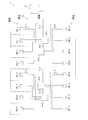
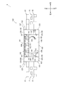
- FIG. 1 is an overall configuration diagram of an air conditioning apparatus 1 according to an embodiment of the present disclosure.
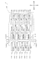
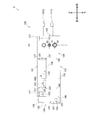
- FIG. 2 is a refrigerant circuit diagram of the air conditioner 1 (only the heat source unit 2 is shown in detail).
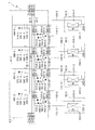
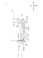
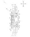
- FIG. 3 is a refrigerant circuit diagram of the air conditioner 1 (only the refrigerant flow path switching unit 4-2 and the usage units 3A-2 to 3D-2 connected thereto are shown in detail).
- the air conditioning apparatus 1 is an apparatus that cools or heats a room such as a building by a vapor compression refrigeration cycle.
- the air conditioner 1 is mainly provided between the heat source unit 2, a plurality (16 in this case) of the use units 3, and the heat source unit 2 and the use unit 3, and switches the flow of the refrigerant in the use unit 3. It has a plurality of (here, four) refrigerant flow path switching units 4, a heat source side refrigerant communication pipe 5 extending from the heat source unit 2, and a utilization side refrigerant communication pipe 6 extending from the utilization unit 4. Therefore, the vapor compression type refrigerant circuit 19 of the air conditioner 1 is configured by connecting the heat source unit 2, the utilization unit 3, the refrigerant flow path switching unit 4, and the refrigerant communication pipes 5 and 6. ing.
- the heat source unit 2 is installed outdoors, such as on the roof of a building.
- the usage unit 3 is provided in the building, and here, is provided in a living room, a space above the ceiling, or the like.
- the refrigerant flow path switching unit 4 is provided in the building, and here, is provided in the space above the ceiling of the passage.
- the heat source unit 2 and the refrigerant flow path switching unit 4 are connected by the heat source side refrigerant communication pipe 5, and the refrigerant is exchanged between the units 2 and 4.
- the heat source unit 2 is connected to the refrigerant flow path switching unit 4-1 by the heat source side refrigerant communication pipe 5-1.
- the refrigerant flow path switching unit 4-1 is connected to the refrigerant flow path switching unit 4-2 by the heat source side refrigerant communication pipe 5-2.
- the refrigerant flow path switching unit 4-2 is connected to the refrigerant flow path switching unit 4-3 by the heat source side refrigerant communication pipe 5-3.
- the refrigerant flow path switching unit 4-3 is connected to the refrigerant flow path switching unit 4-4 by a heat source side refrigerant communication pipe 5-4.
- one of the refrigerant flow path switching units 4 (here, the refrigerant flow path switching unit 4-1) is connected to the heat source unit 2, and the refrigerant flow path switching units 4 are arranged in order from the heat source unit 2. It is connected in series.
- the usage unit 3 and the refrigerant flow path switching unit 4 are connected by the usage-side refrigerant communication pipe 6, and the refrigerant is exchanged between the units 3 and 4.
- the refrigerant flow path switching unit 4-1 is connected to a plurality (here, four) of the usage units 3A-1 to 3D-1 by a usage-side refrigerant communication pipe 6-1.
- the refrigerant flow path switching unit 4-2 is connected to a plurality (here, four) of the usage units 3A-2 to 3D-2 by the usage-side refrigerant communication pipe 6-2.
- the refrigerant flow path switching unit 4-3 is connected to a plurality (here, four) of the usage units 3A-3 to 3D-3 by a usage-side refrigerant communication pipe 6-3.
- the refrigerant flow path switching unit 4-4 is connected to a plurality (here, four) of the usage units 3A-4 to 3D-4 by a usage-side refrigerant communication pipe 6-4.
- the refrigerant flow path switching units 4 are connected to different usage units 3 (here, one set of four usage units 3), and the usage units 3 are connected via the refrigerant flow path switching unit 4. It is connected in parallel.
- the air conditioning apparatus 1 constitutes a so-called cooling / heating free type air conditioning apparatus capable of individually performing the cooling operation or the heating operation for each usage unit 3.
- the heat source unit 2 is connected to the refrigerant flow path switching unit 4 via the heat source side refrigerant communication pipe 5, and constitutes a part of the refrigerant circuit 19.
- the heat source side refrigerant communication pipe 5 has a first heat source side refrigerant communication pipe 7, a second heat source side refrigerant communication pipe 8, and a third heat source side refrigerant communication pipe 9. Therefore, the heat source unit 2 and the refrigerant flow path switching unit 4 are connected by the three heat source side refrigerant communication pipes 7, 8, and 9. Specifically, the heat source unit 2 is connected to the refrigerant flow path switching unit 4-1 by the heat source side refrigerant communication pipes 7-1, 8-1, 9-1. The refrigerant flow path switching unit 4-1 is connected to the refrigerant flow path switching unit 4-2 by heat source side refrigerant communication pipes 7-2, 8-2, 9-2.
- the refrigerant flow path switching unit 4-2 is connected to the refrigerant flow path switching unit 4-3 by heat source side refrigerant communication pipes 7-3, 8-3, 9-3.
- the refrigerant flow path switching unit 4-3 is connected to the refrigerant flow path switching unit 4-4 by heat source side refrigerant communication pipes 7-4, 8-4, 9-4.
- the heat source unit 2 mainly includes a compressor 21, a first heat source side switching valve 22, a heat source side heat exchanger 23, a heat source side expansion valve 24, and a plurality of (here, three) closing valves 25 to 27. And a second heat source side switching valve 29.
- the compressor 21 is a device for compressing a refrigerant, and is composed of, for example, a hermetic compressor in which a compressor motor and a compression element are housed in a casing.
- the first heat source side switching valve 22 and the heat source side heat exchanger are the discharge side of the compressor 21. It is possible to connect the gas side of 23 (see the solid line of the first heat source side switching valve 22 of FIG. 2).
- the first heat source side switching valve 22 is configured so that when the heat source side heat exchanger 23 functions as a refrigerant evaporator (hereinafter, referred to as “heat source side evaporation state”), the suction side of the compressor 21 and the heat source side heat It is possible to connect the gas side of the exchanger 23 (see the broken line of the first heat source side switching valve 22 of FIG. 2).
- the first heat source side switching valve 22 is a device capable of switching the flow direction of the refrigerant flowing through the heat source side heat exchanger 23 (here, the heat source side radiating state and the heat source side evaporating state), for example, , A four-way switching valve.
- the heat source side heat exchanger 23 is a heat exchanger for exchanging heat between the refrigerant and the outdoor air.
- the heat source side heat exchanger 23 has its gas side connected to the first heat source side switching valve 22 and its liquid side connected to the heat source side expansion valve 24.
- the heat source unit 2 has a heat source side fan 28 for generating a flow of outdoor air passing through the heat source side heat exchanger 23.
- the heat source side expansion valve 24 is a device for reducing the pressure of the refrigerant, and is composed of, for example, an electric expansion valve whose opening can be adjusted.
- One end side of the heat source side expansion valve 24 is connected to the liquid side of the heat source side heat exchanger 23, and the other end side thereof is connected to the first closing valve 25.
- the second heat source side switching valve 29 When the refrigerant discharged from the compressor 21 is sent to the second heat source side refrigerant communication pipe 8 (hereinafter, referred to as “refrigerant derivation state”), the second heat source side switching valve 29 is connected to the discharge side of the compressor 21 and the second side. It is possible to connect the second shutoff valve 26 (see the broken line of the second heat source side switching valve 29 in FIG. 2). Further, the second heat source side switching valve 29, when sending the refrigerant flowing through the second heat source side refrigerant communication pipe 8 to the suction side of the compressor 21 (hereinafter, referred to as “refrigerant introduction state”), the second closing valve 26.
- the suction side of the compressor 21 can be connected (see the solid line of the second heat source side switching valve 29 in FIG. 2).
- the second heat source side switching valve 29 is a device capable of switching the flow direction of the refrigerant flowing through the second heat source side refrigerant communication pipe 8 (here, the refrigerant derivation state and the refrigerant introduction state), for example, , A four-way switching valve.
- the closing valves 25 to 27 are manual valves that are opened and closed when the heat source unit 2 and the outside (here, the refrigerant flow path switching unit 4) are connected and disconnected.
- One end side of the first closing valve 25 is connected to the heat source side expansion valve 24, and the other end side thereof is connected to the first heat source side refrigerant communication pipe 7 (here, the first heat source side refrigerant communication pipe 7-1).
- One end side of the second closing valve 26 is connected to the second heat source side switching valve 29, and the other end side thereof is connected to the second heat source side refrigerant communication pipe 8 (here, the second heat source side refrigerant communication pipe 8-1).
- One end side of the third closing valve 27 is connected to the suction side of the compressor 21, and the other end side thereof is connected to the third heat source side refrigerant communication pipe 9 (here, the third heat source side refrigerant communication pipe 9-1). There is.
- the usage unit 3 is connected to the refrigerant flow path switching unit 4 via the usage-side refrigerant communication pipe 6 and constitutes a part of the refrigerant circuit 19.
- the usage-side refrigerant communication tube 6 has a first usage-side refrigerant communication tube 10 and a second usage-side refrigerant communication tube 11. Therefore, the usage unit 3 and the refrigerant flow path switching unit 4 are connected by the usage-side refrigerant communication tubes 10 and 11 of two types.
- the refrigerant flow path switching unit 4-1 includes four sets of use side refrigerant communication tubes 10-1, 11-1 (10A-1 and 11A-1, 10B-1 and 11B-1, 10C-1). And 11C-1, 10D-1 and 11D-1) to the utilization units 3A-1 to 3D-1.
- the refrigerant flow path switching unit 4-2 includes four sets of use side refrigerant communication tubes 10-2, 11-2 (10A-2 and 11A-2, 10B-2 and 11B-2, 10C-2 and 11C-2, 10D-2 and 11D-2) are connected to the usage units 3A-2 to 3D-2.
- the refrigerant flow path switching unit 4-3 includes four sets of use side refrigerant communication tubes 10-3 and 11-3 (10A-3 and 11A-3, 10B-3 and 11B-3, 10C-3 and 11C-3, 10D-3 and 11D-3) are connected to the usage units 3A-3 to 3D-3.
- the refrigerant flow path switching unit 4-4 includes four sets of use side refrigerant communication tubes 10-4 and 11-4 (10A-4 and 11A-4, 10B-4 and 11B-4, 10C-4 and 11C-4, 10D-4 and 11D-4) are connected to the usage units 3A-4 to 3D-4.
- the usage unit 3 mainly has a usage-side expansion valve 31 and a usage-side heat exchanger 32.
- the use-side expansion valve 31 is a device for reducing the pressure of the refrigerant, and is composed of, for example, an electric expansion valve whose opening can be adjusted.
- the use-side expansion valve 31 has one end connected to the first use-side refrigerant communication pipe 10 and the other end connected to the liquid side of the use-side heat exchanger 32.
- the heat exchanger 32 on the use side is a heat exchanger for exchanging heat between the refrigerant and the indoor air.
- the liquid side of the utilization side heat exchanger 32 is connected to the utilization side expansion valve 31, and the gas side thereof is connected to the second utilization side refrigerant communication pipe 11.
- the usage unit 3 has a usage-side fan 33 for generating a flow of indoor air that passes through the usage-side heat exchanger 31.
- the refrigerant flow path switching unit 4 is provided between the heat source unit 2 and the usage unit 3, is connected to the refrigerant flow path switching unit 4 via the heat source side refrigerant communication pipe 5, and is used. It is connected to the refrigerant flow path switching unit 4 via the side refrigerant communication pipe 6 and constitutes a part of the refrigerant circuit 19.
- the refrigerant flow path switching unit 4 mainly includes a first internal communication pipe 41, a second internal communication pipe 42, a third internal communication pipe 43, fourth internal communication pipes 44A to 44D, and a fifth internal communication pipe 45A. To 45D, first flow path switching valves 46A to 46D, and second flow path switching valves 47A to 47D.
- the one end side and / or the other end side of the first internal communication pipe 41 is connected to the first heat source side refrigerant communication pipe 7.
- a first heat source side small nozzle 71 for connecting to the first heat source side refrigerant communication pipe 7 is formed on one end side of the first inner communication pipe 41, and the other end of the first inner communication pipe 41 is formed.
- a second heat source side small nozzle 72 for connecting to the first heat source side refrigerant communication pipe 7 is formed.
- the first internal communication pipe 41 connects the first heat source side small nozzle 71 and the second heat source side small nozzle 72.
- first heat source side small nozzle 71-1 one end side (first heat source side small nozzle 71-1) of the first internal communication pipe 41-1 of the refrigerant flow path switching unit 4-1 is connected to the first heat source side refrigerant communication pipe 7-2.
- the other end side (second heat source side small nozzle 72-1) is connected to the first heat source side refrigerant communication pipe 7-1.
- the first internal communication pipe 41-2 of the refrigerant flow path switching unit 4-2 has one end side (first heat source side small nozzle 71-2) connected to the first heat source side refrigerant communication pipe 7-2 and the other end.
- the side (second heat source side small nozzle 72-2) is connected to the first heat source side refrigerant communication pipe 7-3.
- the first internal communication pipe 41-3 of the refrigerant flow path switching unit 4-3 has one end side (first heat source side small nozzle 71-3) connected to the first heat source side refrigerant communication pipe 7-3 and the other end.
- the side (second heat source side small nozzle 72-3) is connected to the first heat source side refrigerant communication pipe 7-4.
- the first internal communication pipe 41-4 of the refrigerant flow path switching unit 4-4 has one end side (first heat source side small nozzle 71-4) not connected to the first heat source side refrigerant communication pipe and the other end.
- the side (second heat source side small nozzle 72-4) is connected to the first heat source side refrigerant communication pipe 7-4.
- the one end side and / or the other end side of the second internal communication pipe 42 is connected to the second heat source side refrigerant communication pipe 8.
- a first heat source side middle nozzle 81 for connecting to the second heat source side refrigerant communication pipe 8 is formed on one end side of the second inner communication pipe 42, and the other end of the second inner communication pipe 42 is formed.
- a second heat source side middle nozzle 82 for connecting to the second heat source side refrigerant communication pipe 8 is formed.
- the second internal communication pipe 42 connects the first heat source side middle nozzle 81 and the second heat source side middle nozzle 82.
- one end side (first heat source side middle nozzle 81-1) of the second internal communication tube 42-1 of the refrigerant flow path switching unit 4-1 is connected to the second heat source side refrigerant communication tube 8-2.
- the other end side (second heat source side middle nozzle 82-1) is connected to the second heat source side refrigerant communication pipe 8-1.
- the second internal communication pipe 42-2 of the refrigerant flow path switching unit 4-2 has one end side (first heat source side middle nozzle 81-2) connected to the second heat source side refrigerant communication pipe 8-2 and the other end.
- the side (second heat source side middle nozzle 82-2) is connected to the second heat source side refrigerant communication pipe 8-3.
- the second internal communication pipe 42-3 of the refrigerant flow path switching unit 4-3 has one end side (first heat source side middle nozzle 81-3) connected to the second heat source side refrigerant communication pipe 8-3 and the other end.
- the side (second heat source side middle nozzle 82-3) is connected to the second heat source side refrigerant communication pipe 8-4.
- the second internal communication pipe 42-4 of the refrigerant flow path switching unit 4-4 has one end side (first heat source side middle nozzle 81-4) not connected to the second heat source side refrigerant communication pipe and the other end.
- the side (second heat source side middle nozzle 82-4) is connected to the second heat source side refrigerant communication pipe 8-4.
- the one end side and / or the other end side of the third internal communication pipe 43 is connected to the third heat source side refrigerant communication pipe 9.
- a first heat source side large nozzle 91 for connecting to the third heat source side refrigerant communication pipe 9 is formed on one end side of the third inner communication pipe 43, and the other end of the third inner communication pipe 43 is formed.
- a second heat source side large nozzle 92 for connecting to the third heat source side refrigerant communication pipe 9 is formed.
- the third internal communication pipe 43 connects the first heat source side large nozzle 91 and the second heat source side large nozzle 92.
- one end side (first heat source side large nozzle 91-1) of the third internal communication tube 43-1 of the refrigerant flow path switching unit 4-1 is connected to the third heat source side refrigerant communication tube 9-2.
- the other end side (the second heat source side large nozzle 92-1) is connected to the third heat source side refrigerant communication pipe 9-1.
- the third internal communication pipe 43-2 of the refrigerant flow path switching unit 4-2 has one end side (first heat source side large nozzle 91-2) connected to the third heat source side refrigerant communication pipe 9-2 and the other end.
- the side (the second heat source side large nozzle 92-2) is connected to the third heat source side refrigerant communication pipe 9-3.
- the third internal communication pipe 43-3 of the refrigerant flow path switching unit 4-3 has one end side (first heat source side large nozzle 91-3) connected to the third heat source side refrigerant communication pipe 9-3 and the other end.
- the side (the second heat source side large nozzle 92-3) is connected to the third heat source side refrigerant communication pipe 9-4.
- the third internal communication pipe 43-4 of the refrigerant flow path switching unit 4-4 has one end side (first heat source side large nozzle 91-4) not connected to the third heat source side refrigerant communication pipe and the other end.
- the side is connected to the third heat source side refrigerant communication pipe 9-4 (the second heat source side large nozzle 92-4).
- the first heat source side small nozzle 71, the first heat source side middle nozzle 81, and the first heat source side which are connected to the three kinds of heat source side refrigerant communication pipes 7, 8, 9 are provided.
- a plurality (here, four) of the fourth internal communication pipes 44A to 44D are connected to the first internal communication pipe 41.
- Each of the fourth internal communication pipes 44A to 44D is connected such that one end side of the fourth internal communication pipe 44A branches from an intermediate portion of the first internal communication pipe 41.
- the other ends of the fourth internal communication pipes 44A to 44D are connected to the first use-side refrigerant communication pipes 10A to 10D, respectively.
- usage-side small nozzles 101A to 101D connected to the first usage-side refrigerant communication tubes 10A to 10D are formed at the other ends of the fourth internal communication tubes 44A to 44D.
- the fourth internal communication pipes 44A to 44D connect the first internal communication pipe 41 and the use side small nozzles 101A to 101D.
- a plurality of (in this case, four) fifth internal communication pipes 45A to 45D are branched from the second internal communication pipe 42 and sixth internal communication pipes 48A to 48D and a third internal communication pipe 43, respectively. It has seventh internal communication pipes 49A to 49D, and eighth internal communication pipes 50A to 50D for joining the sixth internal communication pipes 48A to 48D and the seventh internal communication pipes 49A to 49D.
- One end side of each of the sixth internal communication pipes 48A to 48D is connected to an intermediate portion of the second internal communication pipe 42, and the other end side thereof is connected to one end side of the eighth internal communication pipes 50A to 50D.
- each of the seventh internal communication pipes 49A to 49D has one end connected to an intermediate portion of the third internal communication pipe 43 and the other end connected to one end of each of the eighth internal communication pipes 50A to 50D.
- the other end of each of the eighth internal communication pipes 50A to 50D is connected to the second usage-side refrigerant communication pipes 11A to 11D.
- use-side large nozzles 111A to 111D connected to the second use-side refrigerant communication pipes 11A to 11D are formed on the other end sides of the eighth internal communication pipes 50A to 50D.
- the fifth internal communication pipes 45A to 45D connect the second internal communication pipe 42 and the third internal communication pipe 43 to the use-side large nozzles 111A to 111D.
- a plurality of (here, four) first flow path switching valves 46A to 46D are provided in the sixth internal communication pipes 48A to 48D, respectively. Further, a plurality of (here, four) second flow path switching valves 47A to 47D are provided in the seventh internal communication pipes 49A to 49D, respectively.
- the first flow path switching valves 46A to 46D and the second flow path switching valves 47A to 47D are, for example, electric expansion valves or electromagnetic valves. Then, the first flow path switching valves 46A to 46D are closed when the corresponding usage units 3A to 3D perform the cooling operation, and are opened when the corresponding usage units 3A to 3D perform the heating operation.
- the corresponding usage units 3A to 3D are Even when the cooling operation is performed, the first flow path switching valves 46A to 46D are opened. Further, the second flow path switching valves 47A to 47D are opened when the corresponding usage units 3A to 3D perform the cooling operation, and closed when the corresponding usage units 3A to 3D perform the heating operation. It In this way, the first flow path switching valves 46A to 46D and the second flow path switching valves 47A to 47D can switch the flow direction of the refrigerant in the usage units 3A to 3D (here, cooling operation and heating operation). Is.
- the sixth internal communication pipes 48A to 48D are provided with first filters 51A to 51D, respectively.
- the first filters 51A to 51D are devices for capturing foreign substances that accompany the refrigerant flowing through the sixth internal communication pipes 48A to 48D.
- the first filters 51A to 51D are provided in portions of the sixth internal communication pipes 48A to 48D between the branch portion from the second internal communication pipe 42 and the first flow path switching valves 46A to 46D.
- Second filters 52A to 52D are provided on the seventh internal connecting tubes 49A to 49D, respectively.
- the second filters 52A to 52D are devices for capturing foreign substances that accompany the refrigerant flowing through the seventh internal communication pipes 49A to 49D.
- the second filters 52A to 52D are provided in portions of the seventh internal communication pipes 49A to 49D between the branch portion from the third internal communication pipe 43 and the second flow path switching valves 47A to 47D.
- Third filters 53A to 53D are provided on the eighth internal communication tubes 50A to 50D, respectively.
- the third filters 53A to 53D are devices for capturing foreign substances that accompany the refrigerant flowing through the eighth internal communication pipes 50A to 50D.
- supercooling heat exchangers 54A to 54D are provided in the fourth internal communication pipes 44A to 44D, respectively, and the ninth internal communication pipes 55A to 55D are connected thereto.
- the subcooling heat exchangers 54A to 54D are devices for cooling the refrigerant flowing through the fourth internal communication pipes 44A to 44D with the refrigerant flowing through the ninth internal communication pipes 55A to 55D, and are, for example, double-pipe type heat exchangers. It consists of an exchange.
- the subcooling heat exchangers 54A to 54D respectively have a flow path for flowing the refrigerant flowing through the fourth internal communication tubes 44A to 44D and a flow path for flowing the refrigerant flowing through the ninth internal communication tubes 55A to 55D. , Are formed.
- each of the ninth internal connecting pipes 55A to 55D is connected so as to branch from the middle of the fourth internal connecting pipes 44A to 44D, and the other end of the ninth internal connecting pipes 55A to 55D merges into the middle of the tenth internal connecting pipe 56. Is connected to.
- the ninth internal communication pipes 55A to 55D are provided with supercooling heat exchangers 54A to 54D (flow passages for flowing the refrigerant flowing through the ninth internal communication pipes 55A to 55D) in the middle.
- fourth filters 57A to 57D and supercooling expansion valves 58A to 58D are provided on the ninth internal communication pipes 55A to 55D, respectively.
- the fourth filters 57A to 57D are devices for capturing foreign substances that accompany the refrigerant flowing through the ninth internal communication pipes 55A to 55D.
- the subcooling expansion valves 58A to 58D are devices for reducing the pressure of the refrigerant, and are composed of, for example, electric expansion valves whose opening can be adjusted.
- the fourth filters 57A to 57D include branch portions of the ninth internal communication pipes 55A to 55D from the fourth internal communication pipes 44A to 44D and the supercooling heat exchangers 54A to 54D (the ninth internal communication pipes 55A to 55D). It is provided in a part between the flow path for flowing the flowing refrigerant).
- the subcooling expansion valves 58A to 58D are provided for flowing the refrigerant flowing through the fourth filters 57A to 57D and the subcooling heat exchangers 54A to 54D (the ninth internal communication pipes 55A to 55D) among the ninth internal communication pipes 55A to 55D.
- An eleventh internal communication pipe 59 is connected to the tenth internal communication pipe 56.
- the eleventh internal communication pipe 59 is connected to the third internal communication pipe 43. Therefore, the tenth internal communication pipe 56 is connected to the third internal communication pipe 43 via the eleventh internal communication pipe 59.
- the air conditioning apparatus 1 having the above circuit configuration can perform cooling only operation, heating only operation, cooling-main operation, and heating-main operation.
- the cooling only operation is an operation in which only the usage unit 3 that performs the cooling operation exists.
- the heating only operation is an operation in which only the usage unit 3 that performs the heating operation exists.
- the cooling-main operation both the use unit 3 performing the cooling operation and the use unit 3 performing the heating operation are mixed, but the heat source unit 2 is in the heat source side heat radiation state (the solid line of the first heat source side switching valve 22 in FIG. 2). (See) is the driving.
- both the use unit 3 performing the cooling operation and the use unit 3 performing the heating operation are mixed, but the heat source unit 2 is in the heat source side evaporation state (broken line of the first heat source side switching valve 22 in FIG. 2). (See) is the driving. Since all of the refrigerant flow path switching units 4-1 to 4-4 have the same configuration, the suffixes "-1" and “-2" of the reference numerals for distinguishing the refrigerant flow path switching units 4 are shown here. , “-3", “-4" and suffixes "A", "B", “C”, “D” of reference numerals for distinguishing the components of the refrigerant flow path switching unit 4 are omitted as much as possible in the description. I do.
- the first heat source side switching valve 22 is switched to the heat source side heat radiating state, and the second heat source side switching valve 29 is introduced with the refrigerant.
- the compressor 21, the heat source side fan 28, and the use side fan 33 are driven. Further, the first flow path switching valve 46 and the second flow path switching valve 47 are opened.
- the refrigerant discharged from the compressor 21 in the heat source unit 2 is sent to the heat source side heat exchanger 23 through the first heat source side switching valve 22, and the heat source side heat exchanger 23 exchanges heat with the outdoor air. Dissipate heat.
- the refrigerant radiating heat in the heat source side heat exchanger 23 flows out from the heat source unit 2 through the heat source side expansion valve 24 and the first closing valve 25.
- the refrigerant flowing out of the heat source unit 2 through the heat source side expansion valve 24 and the first closing valve 25 is a first heat source side refrigerant communication pipe 7-1, a first internal communication pipe 41-1 of the refrigerant flow path switching unit 4-1.
- the first internal communication pipe 41-3, the first heat source side refrigerant communication pipe 7-4, and the first internal communication pipe 41-4 of the refrigerant flow path switching unit 4-4 are sent in this order.
- the refrigerant flowing through the first internal communication pipe 41 is sequentially branched to the fourth internal communication pipe 44. Then, a part of the refrigerant branched to the fourth internal communication pipe 44 is branched to the ninth internal communication pipe 55, and the rest is sent to the supercooling heat exchanger 54.
- the refrigerant branched to the ninth internal communication pipe 55 is also depressurized by the supercooling expansion valve 58 and then sent to the supercooling heat exchanger 54.
- the refrigerant flowing through the fourth internal communication pipe 44 exchanges heat with the refrigerant flowing through the ninth internal communication pipe 55 in the supercooling heat exchanger 54, is cooled, and then flows out from the refrigerant flow path switching unit 4.
- the refrigerant flowing through the ninth internal communication pipe 55 is heated by exchanging heat with the refrigerant flowing through the fourth internal communication pipe 44 in the supercooling heat exchanger 54, and then the tenth internal communication pipe 56 and the eleventh internal communication pipe 56. It is sent to the third internal communication pipe 43 through the internal communication pipe 59.
- the refrigerant flowing out of the refrigerant flow path switching unit 4 is sent to the usage unit 3 through the first usage-side refrigerant communication pipe 10.
- the refrigerant sent to the usage unit 3 is decompressed by the usage expansion valve 31, and then sent to the usage heat exchanger 32.
- the refrigerant sent to the usage-side heat exchanger 32 exchanges heat with room air, evaporates, and flows out from the usage unit 3.
- the refrigerant flowing out from the usage unit 3 is sent to the refrigerant flow path switching unit 4 through the second usage-side refrigerant communication pipe 11.
- the refrigerant sent to the refrigerant flow path switching unit 4 is sent to the eighth internal communication pipe 50, and then branched and sent to the sixth internal communication pipe 48 and the seventh internal communication pipe 49.
- the refrigerant sent to the sixth internal communication pipe 48 is sent to the second internal communication pipe 42 through the first flow path switching valve 46.
- the refrigerant sent to the seventh internal communication pipe 49 is sent to the third internal communication pipe 43 through the second flow path switching valve 47 and merges with the refrigerant flowing through the ninth internal communication pipe 55.
- the refrigerant flowing through the second internal communication pipe 42-4 of the refrigerant flow path switching unit 4-4 flows out from the refrigerant flow path switching unit 4-4, and the second heat source side refrigerant communication pipe 8-4 and the refrigerant flow path switching unit.
- Second internal communication pipe 42-3 of 4-3, second heat source side refrigerant communication pipe 8-3, second internal communication pipe 42-2 of refrigerant flow path switching unit 4-2, second heat source side refrigerant communication pipe 8 -2, the second internal communication pipe 42-1 of the refrigerant flow path switching unit 4-1 and the second heat source side refrigerant communication pipe 8-1 are sent in this order.
- the refrigerants flowing through the second internal communication pipe 42 sequentially merge.
- the refrigerant flowing through the second heat source side refrigerant communication pipe 8-1 after all the refrigerant flowing through the second internal communication pipe 42 merges is sent to the heat source unit 2. Further, the refrigerant flowing through the third internal communication pipe 43-4 of the refrigerant flow path switching unit 4-4 flows out from the refrigerant flow path switching unit 4-4, and the third heat source side refrigerant communication pipe 9-4 and the refrigerant flow path.
- the pipe 9-2, the third internal communication pipe 43-1 of the refrigerant flow path switching unit 4-1, and the third heat source side refrigerant communication pipe 9-1 are sent in this order.
- the refrigerants flowing through the third internal communication pipe 43 sequentially merge.
- the refrigerant flowing through the third heat source side refrigerant communication tube 9-1 after all the refrigerant flowing through the third internal communication tubes 43 have joined together is sent to the heat source unit 2.
- the refrigerant sent to the heat source unit 2 is sucked into the compressor 21 through the second closing valve 26, the second heat source side switching valve 29, and the third closing valve 27, and is compressed again.
- the first heat source side switching valve 22 is switched to the heat source side evaporating state, and the second heat source side switching valve 29 is a refrigerant outlet.
- the compressor 21, the heat source side fan 28, and the use side fan 33 are driven. Further, the first flow path switching valve 46 is opened and the second flow path switching valve 47 is closed.
- the refrigerant discharged from the compressor 21 in the heat source unit 2 flows out from the heat source unit 2 through the second heat source side switching valve 29 and the second closing valve 26.
- the refrigerant flowing out of the heat source unit 2 through the second closing valve 26 is connected to the second heat source side refrigerant communication pipe 8-1, the second internal communication pipe 42-1 of the refrigerant flow path switching unit 4-1 and the second heat source side refrigerant communication.
- the refrigerant flowing through the second internal communication pipe 42 in the refrigerant flow path switching unit 4 is sequentially branched to the sixth internal communication pipe 48. Then, the refrigerant branched to the sixth internal communication pipe 48 flows out from the refrigerant flow switching unit 4 through the first flow switching valve 46 and the eighth internal communication pipe 50.
- the refrigerant flowing out of the refrigerant flow path switching unit 4 is sent to the usage unit 3 through the second usage-side refrigerant communication pipe 11.
- the refrigerant sent to the usage unit 3 is sent to the usage-side heat exchanger 32.
- the refrigerant sent to the use-side heat exchanger 32 exchanges heat with the indoor air and radiates heat.
- the refrigerant radiating heat in the usage-side heat exchanger 32 is decompressed by the usage-side expansion valve 31, and then flows out from the usage unit 3.
- the refrigerant flowing out of the usage unit 3 is sent to the refrigerant flow path switching unit 4 through the first usage-side refrigerant communication pipe 10.
- the refrigerant sent to the refrigerant flow path switching unit 4 is sent to the first internal communication pipe 41 through the fourth internal communication pipe 44.
- the refrigerant flowing through the first internal communication pipe 41-4 of the refrigerant flow path switching unit 4-4 flows out from the refrigerant flow path switching unit 4-4, and the first heat source side refrigerant communication pipe 7-4 and the refrigerant flow path switching unit.
- 4-3 first internal communication pipe 41-3, first heat source side refrigerant communication pipe 7-3, refrigerant flow path switching unit 4-2 first internal communication pipe 41-2, first heat source side refrigerant communication pipe 7 -2, the first internal communication pipe 41-1 of the refrigerant flow path switching unit 4-1 and the first heat source side refrigerant communication pipe 7-1 are sent in this order.
- the refrigerants flowing through the first internal communication pipe 41 sequentially merge.
- the refrigerant flowing through the first heat source side refrigerant communication pipe 7-1 after all the refrigerant flowing through the first internal communication pipe 41 merges is sent to the heat source unit 2.
- the refrigerant sent to the heat source unit 2 is sent to the heat source side expansion valve 24 through the first closing valve 25.
- the refrigerant sent to the heat source side expansion valve 24 is sent to the heat source side heat exchanger 23 after being decompressed by the heat source side expansion valve 24.
- the refrigerant sent to the heat source side heat exchanger 23 exchanges heat with the outdoor air and evaporates.
- the refrigerant evaporated in the heat source side heat exchanger 23 is drawn into the compressor 21 through the first heat source side switching valve 22 and is compressed again.
- the usage unit 3-4 connected to the refrigerant flow path switching unit 4-4 performs the heating operation and the usage is connected to the other refrigerant flow path switching units 4-1 to 4-3.
- the units 3-1, 3-2, 3-3 perform the cooling operation, the first heat source side switching valve 22 is switched to the heat source side heat radiation state, and the second heat source side switching valve 29 is in the refrigerant discharge state. Then, the compressor 21, the heat source side fan 28, and the use side fan 33 are driven.
- first flow path switching valve 46-4 of the refrigerant flow path switching unit 4-4 is opened and the second flow path switching valve 47-4 of the refrigerant flow path switching unit 4-4 is closed.
- the first flow path switching valves 46-1, 46-2, 46-3 of the refrigerant flow path switching units 4-1 to 4-3 are closed, and the first flow path switching units 4-1 to 4-3 of the refrigerant flow path switching units 4-1 to 4-3 are closed.
- the two-passage switching valves 47-1, 47-2, 47-3 are opened.
- a part of the refrigerant discharged from the compressor 21 in the heat source unit 2 is sent to the heat source side heat exchanger 23 through the first heat source side switching valve 22, and the rest is the second heat source side switching valve 29 and the second closing. It flows out of the heat source unit 2 through the valve 26.
- the refrigerant sent to the heat source side heat exchanger 23 exchanges heat with the outdoor air in the heat source side heat exchanger 23 to radiate heat.
- the refrigerant radiating heat in the heat source side heat exchanger 23 flows out from the heat source unit 2 through the heat source side expansion valve 24 and the first closing valve 25.
- the refrigerant flowing out of the heat source unit 2 through the second closing valve 26 is connected to the second heat source side refrigerant communication pipe 8-1, the second internal communication pipe 42-1 of the refrigerant flow path switching unit 4-1 and the second heat source side refrigerant communication.
- the refrigerant flowing through the second internal communication pipe 42-4 of the refrigerant flow path switching unit 4-4 is sequentially branched to the sixth internal communication pipe 48-4. Then, the refrigerant branched to the sixth internal communication pipe 48-4 flows out from the refrigerant flow switching unit 4-4 through the first flow switching valve 46-4 and the eighth internal communication pipe 50-4.
- the refrigerant flowing out of the refrigerant flow path switching unit 4-4 is sent to the usage unit 3-4 through the second usage-side refrigerant communication pipe 11-4.
- the refrigerant sent to the usage unit 3-4 is sent to the usage-side heat exchanger 32-4.
- the refrigerant sent to the use side heat exchanger 32-4 exchanges heat with the indoor air to radiate heat.
- the refrigerant radiating heat in the usage-side heat exchanger 32-4 is decompressed by the usage-side expansion valve 31-4 and then flows out from the usage unit 3-4.
- the refrigerant flowing out of the usage unit 3-4 is sent to the refrigerant flow path switching unit 4-4 through the first usage-side refrigerant communication pipe 10-4.
- the refrigerant sent to the refrigerant flow path switching unit 4-4 is sent to the first internal communication pipe 41-4 through the fourth internal communication pipe 44-4.
- the refrigerant flowing out of the heat source unit 2 through the heat source side expansion valve 24 and the first closing valve 25 is a first heat source side refrigerant communication pipe 7-1, a first internal communication pipe 41-1 of the refrigerant flow path switching unit 4-1.
- One internal communication pipe 41-3 is sent in this order.
- the refrigerant flowing through the first internal communication pipe 41-4 of the refrigerant flow path switching unit 4-4 merges with the refrigerant through the first heat source side refrigerant communication pipe 7-4.
- the refrigerant flowing through the first internal communication pipes 41-1, 41-2, 41-3 in the refrigerant flow path switching units 4-1, 4-2, 4-3 has the fourth internal communication pipes 44-1, 44-3. -2, 44-3 are sequentially branched. Then, a part of the refrigerant branched into the fourth internal communication pipes 44-1 44-2 and 44-3 is branched into the ninth internal communication pipes 55-1, 55-2 and 55-3, and the remaining Is sent to the subcooling heat exchangers 54-1, 54-2, 54-3.
- the refrigerant branched to the ninth internal communication pipes 55-1, 55-2, 55-3 is also decompressed by the supercooling expansion valves 58-1, 58-2, 58-3, and then the supercooling heat exchanger 54- 1, 54-2, 54-3.
- the refrigerant flowing through the fourth internal communication pipes 44-1, 44-2, 44-3 is the ninth internal communication pipes 55-1, 55- in the subcooling heat exchangers 54-1, 54-2, 54-3. After cooling by exchanging heat with the refrigerant flowing through 2, 55-3, the refrigerant flows out from the refrigerant flow path switching units 4-1, 4-2, 4-3.
- the refrigerant flowing through the ninth internal communication pipes 55-1, 55-2, 55-3 is the fourth internal communication pipe 44-1 in the subcooling heat exchangers 54-1, 54-2, 54-3.
- the tenth internal communication pipes 56-1, 56-2, 56-3 and the eleventh internal communication pipes 59-1, 59-2 are heated after performing heat exchange with the refrigerant flowing through 44-2, 44-3. , 59-3 to the third internal communication pipes 43-1, 43-2, 43-3.
- the refrigerant flowing out of the refrigerant flow path switching units 4-1, 4-2, 4-3 passes through the first usage-side refrigerant communication tubes 10-1, 10-2, 10-3 to the usage units 3-1, 3-2. Sent to 3-3.
- the refrigerant sent to the use units 3-1, 3-2, 3-3 is decompressed by the use-side expansion valves 31-1, 31-2, 31-3, and then the use-side heat exchanger 32-1, 32-2 and 32-3.
- the refrigerant sent to the use side heat exchangers 32-1, 32-2, 32-3 performs heat exchange with the indoor air, evaporates, and flows out from the use units 3-1, 3-2, 3-3. ..
- the refrigerant flowing out from the usage units 3-1, 3-2, 3-3 passes through the second usage-side refrigerant communication pipes 11-1, 11-2, 11-3 and the refrigerant flow path switching units 4-1, 4-2. , 4-3.
- the refrigerant sent to the refrigerant flow path switching units 4-1, 4-2, 4-3 receives the eighth internal communication pipes 50-1, 50-2, 50-3, the second flow path switching valve 47-1,
- the 9th internal is sent to the 3rd internal connecting pipes 43-1, 43-2, 43-3 through the 7th internal connecting pipes 49-1, 49-2, 49-3 including 47-2, 47-3. It joins with the refrigerant flowing through the connecting pipes 55-1, 55-2, 55-3.
- the refrigerant flowing through the third internal communication pipe 43-3 of the refrigerant flow path switching unit 4-3 flows out from the refrigerant flow path switching unit 4-3, and the third heat source side refrigerant communication tube 9-3 and the refrigerant flow path switching unit.
- 4-2 third internal communication pipe 43-2, third heat source side refrigerant communication pipe 9-2, refrigerant flow path switching unit 4-1 third internal communication pipe 43-1, third heat source side refrigerant communication pipe 9 -1 is sent in order.
- the refrigerants flowing through the third internal communication tubes 43-1, 43-2, 43-3 in the refrigerant flow path switching units 4-1, 4-2, 4-3 join in sequence.
- the refrigerant flowing through the third heat source side refrigerant communication tube 9-1 after all the refrigerant flowing through the third internal communication tubes 43-1, 43-2, 43-3 have joined together is sent to the heat source unit 2.
- the refrigerant sent to the heat source unit 2 is sucked into the compressor 21 through the third closing valve 27 and is compressed again.
- the utilization unit 3-4 connected to the refrigerant flow passage switching unit 4-4 performs the cooling operation and the utilization unit 3-4 connected to the other refrigerant flow passage switching units 4-1 to 4-3.
- the units 3-1, 3-2, 3-3 perform the heating operation
- the first heat source side switching valve 22 is switched to the heat source side evaporation state
- the second heat source side switching valve 29 is in the refrigerant discharge state.
- the compressor 21, the heat source side fan 28, and the use side fan 33 are driven.
- the first flow path switching valve 46-4 of the refrigerant flow path switching unit 4-4 is closed and the second flow path switching valve 47-4 of the refrigerant flow path switching unit 4-4 is opened.
- the first flow path switching valves 46-1, 46-2, 46-3 of the refrigerant flow path switching units 4-1 to 4-3 are opened, and the first flow path switching units 4-1 to 4-3 of the refrigerant flow path switching units 4-1 to 4-3 are opened.
- the two-passage switching valves 47-1, 47-2, 47-3 are closed.
- the refrigerant discharged from the compressor 21 in the heat source unit 2 flows out from the heat source unit 2 through the second heat source side switching valve 29 and the second closing valve 26.
- the refrigerant flowing out of the heat source unit 2 through the second closing valve 26 is connected to the second heat source side refrigerant communication pipe 8-1, the second internal communication pipe 42-1 of the refrigerant flow path switching unit 4-1 and the second heat source side refrigerant communication.
- Pipe 8-2, second internal communication pipe 42-2 of refrigerant flow path switching unit 4-2, second heat source side refrigerant communication pipe 8-3, second internal communication pipe 42- of refrigerant flow path switching unit 4-3 It is sent in the order of 3.
- the refrigerant flowing through the second internal communication pipes 42-1, 42-2, 42-3 of the refrigerant flow path switching units 4-1, 4-2, 4-3 is the sixth internal communication pipes 48-1, 48. -2, 48-3 are sequentially branched.
- the refrigerant branched to the sixth internal communication pipes 48-1, 48-2, 48-3 is the first flow path switching valves 46-1, 46-2, 46-3 and the eighth internal communication pipe 50-. It flows out from the refrigerant flow path switching units 4-1, 4-2, 4-3 through 1, 50-2, 50-3.
- the refrigerant flowing out of the refrigerant flow path switching units 4-1, 4-2, 4-3 passes through the second usage-side refrigerant communication tubes 11-1, 11-2, 11-3 to the usage units 3-1 and 3-2. Sent to 3-3.
- the refrigerant sent to the usage units 3-1, 3-2, 3-3 is sent to the usage-side heat exchangers 32-1, 32-2, 32-3.
- the refrigerant sent to the use side heat exchangers 32-1, 32-2, 32-3 exchanges heat with the indoor air to radiate heat.
- the refrigerant radiating heat in the use side heat exchangers 32-1, 32-2, 32-3 is decompressed by the use side expansion valves 31-1, 31-2, 31-3, and then the use units 3-1 and 3 -It flows out from 2 and 3-3.
- the refrigerant flowing out from the usage units 3-1, 3-2, 3-3 passes through the first usage-side refrigerant communication tubes 10-1, 10-2, 10-3, and the refrigerant flow path switching units 4-1, 4-2. , 4-3.
- the refrigerant sent to the refrigerant flow path switching units 4-1, 4-2, 4-3 passes through the fourth internal communication tubes 44-1, 44-2, 44-3 to the first internal communication tubes 41-1, 44. -2, 44-3.
- the refrigerant flowing through the first internal communication pipe 41-3 of the refrigerant flow path switching unit 4-3 flows out from the refrigerant flow path switching unit 4-3, and the first heat source side refrigerant communication pipe 7-3 and the refrigerant flow path switching unit.
- 4-2 first internal communication pipe 41-2, first heat source side refrigerant communication pipe 7-2, first internal communication pipe 41-1 of refrigerant flow path switching unit 4-1, first heat source side refrigerant communication pipe 7 -1 is sent in order.
- the refrigerants flowing through the first internal communication pipes 41-1, 41-2, 41-3 in the refrigerant flow path switching units 4-1, 4-2, 4-3 join in sequence.
- this refrigerant is sent to the refrigerant flow path switching unit 4-4 through the first heat source side refrigerant communication pipe 7-4. Then, the first heat source side refrigerant communication pipe 7 after all the refrigerants flowing through the first internal communication pipes 41-1, 41-2, 41-3 excluding the refrigerant sent to the refrigerant flow path switching unit 4-4 have joined together The refrigerant flowing through ⁇ 1 is sent to the heat source unit 2.
- the refrigerant sent to the refrigerant flow path switching unit 4-4 is sequentially branched from the first internal communication pipe 41-4 to the fourth internal communication pipe 44-4. Then, a part of the refrigerant branched to the fourth internal communication pipe 44-4 is branched to the ninth internal communication pipe 55-4, and the rest is sent to the supercooling heat exchanger 54-4.
- the refrigerant branched to the ninth internal communication pipe 55-4 is also depressurized by the supercooling expansion valve 58-4 and then sent to the supercooling heat exchanger 54-4.
- the refrigerant flowing through the fourth internal communication pipe 44-4 is cooled by performing heat exchange with the refrigerant flowing through the ninth internal communication pipe 55-4 in the subcooling heat exchanger 54-4, and then cooled.
- the refrigerant flowing through the ninth internal communication pipe 55-4 is heated by exchanging heat with the refrigerant flowing through the fourth internal communication pipe 44-4 in the subcooling heat exchanger 54-4, and then heated in the tenth internal communication pipe 54-4. It is sent to the third internal communication pipe 43-4 through the communication pipe 56-4 and the eleventh internal communication pipe 59-4.
- the refrigerant flowing out of the refrigerant flow path switching unit 4-4 is sent to the usage unit 3-4 through the first usage-side refrigerant communication pipe 10-4.
- the refrigerant sent to the usage unit 3-4 is decompressed by the usage-side expansion valve 31-4 and then sent to the usage-side heat exchanger 32-4.
- the refrigerant sent to the usage-side heat exchanger 32-4 exchanges heat with room air, evaporates, and flows out from the usage unit 3-4.
- the refrigerant flowing out from the usage unit 3-4 is sent to the refrigerant flow path switching unit 4-4 through the second usage-side refrigerant communication pipe 11-4.
- the refrigerant sent to the refrigerant flow path switching unit 4-4 passes through the eighth internal communication tube 50-4 and the seventh internal communication tube 49-4 including the second flow path switching valve 47-4 to the third internal communication tube 43. -4, and joins the refrigerant flowing through the ninth internal communication pipe 55-4.
- the refrigerant flowing through the third internal communication pipe 43-4 of the refrigerant flow path switching unit 4-4 flows out from the refrigerant flow path switching unit 4-4, and the third heat source side refrigerant communication pipe 9-3 and the refrigerant flow path switching unit.
- 4-2 third internal communication pipe 43-2, third heat source side refrigerant communication pipe 9-2, refrigerant flow path switching unit 4-1 third internal communication pipe 43-1, third heat source side refrigerant communication pipe 9 -1 is sent in order.
- the refrigerant flowing through the third heat source side refrigerant communication tube 9-1 is sent to the heat source unit 2.
- the refrigerant sent to the heat source unit 2 through the first heat source side refrigerant communication pipe 7-1 is sent to the heat source side expansion valve 24 through the first closing valve 25.
- the refrigerant sent to the heat source side expansion valve 24 is sent to the heat source side heat exchanger 23 after being decompressed by the heat source side expansion valve 24.
- the refrigerant sent to the heat source side heat exchanger 23 exchanges heat with the outdoor air and evaporates.
- the refrigerant evaporated in the heat source side heat exchanger 23 is sent to the suction side of the compressor 21 through the first heat source side switching valve 22. Then, this refrigerant is sucked into the compressor 21 and compressed again together with the refrigerant sent to the heat source unit 2 through the third heat source side refrigerant communication pipe 9-1.
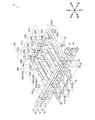
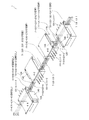
- FIG. 4 is a perspective view showing an outer appearance of the refrigerant flow path switching unit 4 (a state in which the electrical component box 140 is attached to the front side surface plate 123).
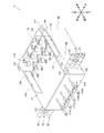
- FIG. 5 is a perspective view showing the circuit configuration of the refrigerant channel switching unit 4.
- FIG. 6 is a top view showing an external appearance of the refrigerant flow path switching unit 4 (a state in which the electrical component box 140 is attached to the front side surface plate 123).
- FIG. 7 is a top view showing the circuit configuration of the refrigerant channel switching unit 4.
- FIG. 8 is a left side view showing the appearance of the refrigerant flow path switching unit 4 (a state in which the electrical component box 140 is attached to the front side surface plate 123).
- FIG. 9 is a left side view showing the circuit configuration of the refrigerant flow path switching unit 4.
- FIG. 10 is a right side view showing the appearance of the refrigerant flow path switching unit 4 (a state in which the electrical component box 140 is attached to the front side surface plate 123).
- FIG. 11 is a rear side view showing the external appearance of the refrigerant channel switching unit 4.
- FIG. 12 is a front side view showing the appearance of the refrigerant flow path switching unit 4 (a state in which the electrical component box 140 is attached to the front side surface plate 123).
- FIG. 13 is a diagram showing details of the heat source side connecting nozzles (heat source side small nozzles 71, 72, heat source side middle nozzles 81, 82, and heat source side large nozzles 91, 92).
- FIG. 14 is a front side view showing the appearance of the refrigerant flow path switching unit 4 (a state in which the box lid 142 of the electrical component box 140 mounted on the front side surface plate 123 is removed).
- FIG. 15 is a perspective view showing the appearance of the refrigerant flow path switching unit 4 (a state in which the electrical component box 140 is attached to the left side plate 125).
- FIG. 16 is a left side view showing the appearance of the refrigerant flow path switching unit 4 (a state in which the box lid 142 of the electrical component box 140 mounted on the left side face plate 125 is removed).
- FIG. 17 is a perspective view showing the appearance of the refrigerant flow path switching unit 4 (a state in which the electrical component box 140 is attached to the right side plate 126).
- FIG. 18 is a right side view showing the appearance of the refrigerant flow path switching unit 4 (a state in which the box lid 142 of the electrical component box 140 mounted on the right side plate 126 is removed).
- FIG. 19 is a perspective view (a state in which the electrical component box 140 is attached to the front side surface plate 123) showing the configuration of the connection between the refrigerant flow path switching units 4-1, 4-2, 4-3, and 4-4.
- FIG. 20 is a top view showing the configuration of the connection between the refrigerant flow path switching units 4-1, 4-2, 4-3, 4-4 (in which the electrical component box 140 is attached to the front side plate 123).
- FIG. 21 is a perspective view showing a configuration of the connection between the refrigerant flow path switching units 4-1, 4-2, 4-3, 4-4 (a state in which the electrical component box 140 is attached to the left side plate 125 or the right side plate 126).
- FIG. 22 is a top view showing the configuration of the connection between the refrigerant flow path switching units 4-1, 4-2, 4-3, 4-4 (a state in which the electrical component box 140 is attached to the left side plate 125 or the right side plate 126). Is.
- the refrigerant flow path switching unit 4 mainly has a case 120 and an electrical component box 140.
- the case 120 the circuit configuration (internal communication pipe, flow path switching valve, etc.) described above is housed.
- the electrical component box 140 accommodates electrical components that control the devices (such as the flow path switching valve and the supercooling expansion valve) inside the case 120.
- the case 120 is a box having a substantially rectangular parallelepiped shape, and mainly includes an upper surface plate 121 that forms an upper surface of the case 120, a lower surface plate 122 that forms a lower surface of the case 120, and a side surface plate 123 that forms a side surface of the case 120. And 124, 125, 126.
- the front side surface plate 123 constitutes the front side surface of the side surfaces of the case 120.
- the rear side surface plate 124 constitutes a rear side surface facing the front side surface (front side surface plate 123) of the side surfaces of the case 120.
- the left side surface plate 125 constitutes a left side surface facing the direction intersecting the front side surface (front side surface plate 123) and the rear side surface (rear side surface plate 124) of the side surfaces of the case 120.
- the right side surface plate 126 constitutes a right side surface facing the left side surface (the left side surface plate 125) of the side surfaces of the case 120.
- the refrigerant flow path switching unit 4 is a hanging type unit.
- the case 120 is provided with a plurality of (four in this case) fixtures 127 for fixing to the installation place via fixtures such as hanging bolts extending downward from above.
- the fixture attachment portions 128 and 129 are formed on the front side end and the rear side face end of the left side plate 125, and the fixture 127 is attached to the fixture by screwing or the like. It is fixed to the portions 128 and 129.
- fixed tool mounting portions 130 and 131 are formed at the end portions of the right side plate 126 near the front side surface and the rear side surface, respectively, and the fixed tool 127 is fixed to the fixed tool mounting portion by screwing or the like. It is fixed to 130 and 131.
- the to-be-fixed tool mounting part 130 is arranged at a position facing the to-be-fixed tool mounting part 128 formed at the end portion of the right side plate 126 closer to the front side surface than the end surface of the left side plate 125 closer to the front side surface.
- the fixed tool mounting portion 131 is arranged at a position facing the rear surface side end of the right side plate 126 and facing the fixed tool mounting part 131 formed at the rear side end of the left side plate 125. ing.
- the left side surface plate 125 has a first heat source side small nozzle 71, a first heat source side middle nozzle 81, and a first heat source side large nozzle, which are first heat source side connecting nozzles connected to the heat source side refrigerant communication pipes 7, 8, 9. 91 is provided. Further, on the right side plate 126, the second heat source side small nozzle 72, the second heat source side middle nozzle 82, and the second heat source side which are the second heat source side connecting nozzles connected to the heat source side refrigerant communication pipes 7, 8, 9 are provided. A large nozzle 92 is provided.
- the refrigerant flow path switching unit 4 is provided with two sets of heat source side connecting nozzles (here, the heat source side small nozzle, the heat source side medium nozzle, and the heat source side large nozzle). Further, the rear side plate 124 is provided with a plurality of use side small nozzles 101A to 101D and use side large nozzles 111A to 111D as use side communication nozzles connected to the use side refrigerant communication pipes 10 and 11 (four sets here). ) Is provided.
- the heat source side connecting nozzles 71, 72, 81, 82, 91, 92 and the use side connecting nozzles 101A to 101D, 111A to 111D are each provided with a heat insulating material around them, but they are not shown here. ing.
- the first heat source side small nozzle 71 is a tubular portion protruding leftward from the left side plate 125.
- the first heat source side small nozzle 71 is arranged closer to the rear side surface plate 123 of the left side surface plate 125 (at least behind the center in the front-rear direction).
- the first heat source side small nozzle 71 is disposed in front of the fixture mounting portion 129 and in the vicinity of the center in the up-down direction in the portion near the rear side surface plate 123 of the left side surface plate 125. .. Then, the first heat source side small nozzle 71 penetrates the left side plate 125 and is connected to one end side of the first internal communication pipe 41 in the case 120.
- the second heat source side small nozzle 72 is a tubular portion that projects rightward from the right side plate 126.
- the second heat source side small nozzle 72 has the same diameter as the first heat source side small nozzle 71.
- the second heat source side small nozzle 72 is arranged closer to the rear side plate 123 of the right side plate 126 (at least behind the center in the front-rear direction). Specifically, the second heat source side small nozzle 72 is arranged in front of the fixed tool attachment part 131 and in the vicinity of the center in the up-down direction in the portion near the rear side surface plate 123 of the right side surface plate 126. ..
- the second heat source side small nozzle 72 is arranged at a position where it abuts on the right side face plate 126 when the first heat source side small nozzle 71 is virtually extended toward the right side face plate 126 along the axial direction of the left side face plate 125.
- the nozzle extension line P1 is a line that passes through the pipe centers (axial centers) of the first heat source side small nozzle 71 and the first heat source side small nozzle 72. Then, the second heat source side small nozzle 72 penetrates the right side surface plate 126 and is connected to the other end side of the first internal communication pipe 41 in the case 120.
- the first heat source side middle nozzle 81 is a tubular portion protruding leftward from the left side plate 125.
- the first heat source side middle nozzle 81 has a larger diameter than the first heat source side small nozzle 71.
- the first heat-source-side middle nozzle 81 is arranged closer to the rear side surface plate 123 of the left side surface plate 125 (at least behind the center in the front-rear direction). Specifically, the first heat-source-side middle nozzle 81 is located in front of the fixture mounting portion 129 and above the first heat-source-side small nozzle 71 in a portion near the rear side surface plate 123 of the left side surface plate 125. It is arranged.
- the first heat source side small nozzles 71 and the first heat source side middle nozzles 81 are arranged in a line along the up-down direction of the left side plate 125 (see the arrangement direction line P4).
- the arrangement direction line P4 is a line connecting the tube centers of the first heat source side small nozzle 71 and the first heat source side middle nozzle 81 (in other words, a line orthogonal to the nozzle extension lines P1 and P2 on the left side plate 125). is there.
- the first heat source side middle nozzle 81 penetrates the left side face plate 125 and is connected to one end side of the second internal communication pipe 42 in the case 120.
- the second heat source side middle nozzle 82 is a tubular portion that projects rightward from the right side surface plate 126.
- the second heat source side middle nozzle 82 has a larger diameter than the first heat source side middle nozzle 72.
- the second heat source side middle nozzle 82 has the same diameter as the first heat source side middle nozzle 81.
- the second heat source side middle nozzle 82 is arranged closer to the rear side plate 123 of the right side plate 126 (at least behind the center in the front-rear direction).
- the second heat-source-side middle nozzle 82 is located in front of the fixture mounting portion 131 and above the second heat-source-side small nozzle 72 in a portion near the rear side surface plate 123 of the right side surface plate 126. It is arranged.
- the second heat source side middle nozzle 82 is located at a position where it abuts on the right side face plate 126 when the first heat source side middle nozzle 81 is virtually extended toward the right side face plate 126 along the axial direction of the left side face plate 125. It is arranged (see nozzle extension line P2).
- the nozzle extension line P2 is a line that passes through the tube centers (axial centers) of the first heat source side middle nozzle 81 and the second heat source side middle nozzle 82.
- the second heat source side small nozzles 72 and the second heat source side middle nozzles 82 are arranged side by side in a row along the up-down direction of the right side plate 126 (see array direction line P4).
- the arrangement direction line P4 is a line connecting the tube centers of the second heat source side small nozzle 72 and the second heat source side middle nozzle 82 (in other words, a line orthogonal to the nozzle extension lines P1 and P2 on the right side plate 126). is there. Then, the second heat source side middle nozzle 82 penetrates the right side plate 126 and is connected to the other end side of the second internal communication pipe 42 in the case 120.
- the first heat source side large nozzle 91 is a tubular portion protruding leftward from the left side plate 125.
- the first heat source side large nozzle 91 has a larger diameter than the first heat source side small nozzle 71 and the first heat source side middle nozzle 81.
- the first heat source side large nozzle 91 is arranged closer to the rear side surface plate 123 of the left side surface plate 125 (at least behind the center in the front-rear direction).
- the first heat-source-side large nozzle 91 is located in front of the fixture attachment part 129 and below the first heat-source-side small nozzle 71 in a portion near the rear side surface plate 123 of the left side surface plate 125. It is arranged.
- the first heat source side small nozzle 71 is arranged between the first heat source side middle nozzle 81 and the first heat source side large nozzle 91.
- the first heat source side small nozzle 71, the first heat source side middle nozzle 81, and the first heat source side large nozzle 91 are arranged in a line along the up-down direction of the left side plate 125 (see the arrangement direction line P4).
- the arrangement direction line P4 is a line connecting the pipe centers of the first heat source side small nozzle 71, the first heat source side middle nozzle 81, and the first heat source side large nozzle 91 (in other words, the nozzle extension line P1 in the left side plate 125). , P2, P3).
- the first heat source side large nozzle 91 penetrates the left side plate 125 and is connected to one end side of the third internal communication pipe 43 in the case 120.
- the second large nozzle 92 on the heat source side is a tubular portion protruding rightward from the right side plate 126.
- the second heat source side large nozzle 92 has a larger diameter than the second heat source side small nozzle 72 and the second heat source side middle nozzle 82. Further, the second heat source side large nozzle 92 has the same diameter as the first heat source side large nozzle 91.
- the second heat source side large nozzle 92 is arranged closer to the rear side plate 123 of the right side plate 126 (at least behind the center in the front-rear direction).
- the second heat-source-side large nozzle 92 is located in front of the fixture mounting portion 131 and below the second heat-source-side small nozzle 72 in a portion near the rear side plate 123 of the right side plate 126. It is arranged.
- the second heat source side small nozzle 72 is arranged between the second heat source side middle nozzle 82 and the second heat source side large nozzle 92.
- the second heat source side large nozzle 92 is located at a position where it abuts on the right side face plate 126 when the first heat source side large nozzle 91 is virtually extended toward the right side face plate 126 along the axial direction of the left side face plate 125. It is arranged (see nozzle extension line P3).
- the nozzle extension line P3 is a line that passes through the pipe centers (axial centers) of the first heat source side large nozzle 91 and the second heat source side large nozzle 92.
- the second heat source side small nozzles 72, the second heat source side middle nozzles 82, and the second heat source side large nozzles 92 are arranged in a line along the up-down direction of the right side plate 126 (see arrangement direction line P4).
- the arrangement direction line P4 is a line connecting the pipe centers of the second heat source side small nozzle 72, the second heat source side middle nozzle 82, and the second heat source side large nozzle 92 (in other words, the nozzle extension lines P1, P2 in the right side plate 126, A line orthogonal to P3).
- the second heat source side large nozzle 92 penetrates the right side surface plate 126 and is connected to the other end side of the third internal communication pipe 43 in the case 120.
- the length L1 of the first heat source side connecting nozzle (the first heat source side small nozzle 71, the first heat source side middle nozzle 81, and the first heat source side large nozzle 91) is 100 mm or more from the left side face plate 125.
- the first heat source side small nozzle 71, the first heat source side middle nozzle 81, and the first heat source side large nozzle 91 have the same length.
- the length L2 of the second heat source side connecting nozzle (the second heat source side small nozzle 72, the second heat source side middle nozzle 82, and the second heat source side large nozzle 92) is 100 mm or more from the right side plate 126.
- the second heat source side small nozzle 72, the second heat source side middle nozzle 82, and the second heat source side large nozzle 92 have the same length.
- the first heat source side connecting nozzle (first heat source side small nozzle 71, first heat source side middle nozzle 81 and first heat source side large nozzle 91), and second heat source side connecting nozzle (second heat source side small nozzle 72, The second heat source side middle nozzle 82 and the second heat source side large nozzle 92) are formed with different diameter portions having at least two different diameters.
- second heat source side connecting nozzle (second heat source side small nozzle 72,
- the second heat source side middle nozzle 82 and the second heat source side large nozzle 92) are formed with different diameter portions having at least two different diameters.
- each of the first heat source side communication nozzle and the second heat source side communication nozzle is formed with a different diameter portion having a shape in which the diameter gradually changes toward the tip.
- the first heat source side small nozzle 71 and the second heat source side small nozzle 72 are formed with different diameter portions 73 that change in diameter so as to decrease in four steps toward the tip.
- the different-diameter portion 73 has a larger diameter than the first portion 74 (diameter d11), the second portion 75 (diameter d12) smaller than the first portion 74, and the second portion 75 in order toward the tip. It has a third portion 76 (diameter d13) having a smaller diameter and a fourth portion 77 (diameter d14) having a smaller diameter than the third portion 76.
- the different-diameter portion 73 is cut at any position of the first portion 74 (cutting line X1), the second portion 75 (cutting line X2), and the third portion 76 (cutting line X3).
- the diameter of the first heat source side small nozzle 71 and the second heat source side small nozzle 72 can be changed to any of d11, d12, d13 and d14 by not cutting at any position.
- the different-diameter portion 73 is not limited to the one whose diameter changes in four steps, but may change in two steps, three steps, or five steps or more.
- first heat source side middle nozzle 81 and the second heat source side middle nozzle 82 are formed with different diameter portions 83 that change in diameter so as to decrease in two steps toward the tip.
- the different-diameter portion 83 has a largest-diameter first portion 84 (diameter d21) and a second portion 85 (diameter d22) smaller in diameter than the first portion 84 in order toward the tip. ..
- the first portion 84 of the different diameter portion 83 has the same length as the total length of the first portion 74 and the second portion 75 of the different diameter portion 73.
- the second portion 85 of the different diameter portion 83 has the same length as the total length of the third portion 76 and the fourth portion 77 of the different diameter portion 73.
- the diameter d21 of the first portion 84 of the different diameter portion 83 is larger than the diameters d11 and d12 of the first portion 74 and the second portion 75 of the different diameter portion 73.
- the diameter d22 of the second portion 85 of the different diameter portion 83 is larger than the diameters d13 and d14 of the third portion 76 and the fourth portion 77 of the different diameter portion 73.
- the different-diameter portion 83 is cut at any position of the first portion 84 (cutting line X1, cutting line X2) and the second portion 85 (cutting line X3), or at any position.
- the diameter of the first heat source side middle nozzle 81 and the second heat source side middle nozzle 82 can be changed to either d21 or d22.
- the different-diameter portion 83 is not limited to the one whose diameter changes in two steps, and may change in three or more steps.
- first heat source side large nozzle 91 and the second heat source side large nozzle 92 are formed with different diameter portions 93 that change in diameter so as to decrease in three steps toward the tip.
- the different diameter portion 93 has a largest diameter first portion 94 (diameter d31), a second portion 95 (diameter d32) smaller in diameter than the second portion 94, and a second portion 95 in order toward the tip. It has a third portion 96 (diameter d33) having a smaller diameter.
- the first portion 84 of the different diameter portion 93 has the same length as the first portion 74 of the different diameter portion 73.
- the second portion 95 of the different diameter portion 93 has the same length as the total length of the first portion 75 and the third portion 76 of the different diameter portion 73.
- the third portion 96 of the different diameter portion 93 has the same length as the fourth portion 77 of the different diameter portion 73.
- the diameter d31 of the first portion 94 of the different diameter portion 93 is larger than the diameter d11 of the first portion 74 of the different diameter portion 73 and the diameter d21 of the first portion 84 of the different diameter portion 83.
- the diameter d32 of the second portion 95 of the different diameter portion 93 is the diameter d13, d14 of the second portion 75 and the third portion 76 of the different diameter portion 73 and the diameter d21 and the second portion of the first portion 84 of the different diameter portion 83. It is larger than the diameter d22 of 85.
- the diameter d33 of the third portion 96 of the different diameter portion 93 is larger than the diameter d22 of the fourth portion 77 of the different diameter portion 73 and the second portion 85 of the different diameter portion 83. Then, the different diameter portion 93 is cut at any position of the first portion 94 (cutting line X1) and the second portion 95 (cutting lines X2, X3), or cut at any position.
- the diameters of the first heat source side large nozzle 91 and the second heat source side large nozzle 92 can be changed to any one of d31, d32, and d33.
- the different-diameter portion 93 is not limited to the one whose diameter changes in three steps, and may change in two steps or may change in four steps or more.
- Intervals between the first heat source side connecting nozzles and intervals between the second heat source side connecting nozzles are 40 mm or more.
- the distance S1 between the first portion 74 and the first portion 84 where the distance between the nozzles is minimum is 40 mm or more.
- both nozzles are The distance S2 between the first portion 74 and the first portion 94 that minimizes the distance is 40 mm or more.
- the small nozzles 101A to 101D on the use side are tubular portions protruding rearward from the rear side plate 124.
- the use-side small nozzles 101A to 101D are arranged side by side in the left-right direction.
- the use-side small nozzles 101A to 101D are arranged closer to the upper surface plate 121 of the rear side surface plate 124 (at least above the center in the vertical direction).
- the use-side small nozzles 101A to 101D penetrate the rear side surface plate 124 and are connected to the other end side of the fourth internal communication pipes 44A to 44D in the case 120.
- the large nozzle 111 on the use side is a tubular portion that projects rearward from the rear side plate 124.
- the use-side large nozzle 111 has a larger diameter than the use-side small nozzle 101.
- the use-side large nozzles 111A to 111D are arranged side by side in the left-right direction. Further, the use-side large nozzles 111A to 111D are arranged below the use-side small nozzles 101A to 101D in the rear side surface plate 124.
- the large nozzles 111A to 111D on the use side penetrate the rear side plate 124 and are connected to the other end side of the fifth internal communication pipes 45A to 45D (eighth internal communication pipes 50A to 50D) in the case 120. Has been done.
- the first internal communication pipe 41 includes a left side face plate 125, a front side face plate 123, and a right side face plate 126 from an end portion on the first heat source side small nozzle 71 side to an end portion on the second heat source side small nozzle 72 side. It extends in order.
- the heat source side small nozzles 71 and 72 can be said to be a part of the first internal communication pipe 41, but here, for convenience of description, a portion inside the case 120 is referred to as a first internal communication pipe 41, and The portions outside 120 are called heat source side small nozzles 71 and 72.
- the second internal communication pipe 42 extends straight from the end on the first heat source side middle nozzle 81 side to the end on the second heat source side middle nozzle 82 side through the nozzle extension line P2. ..
- the heat source side middle nozzles 81 and 82 can be said to be a part of the second internal communication pipe 42, but here, for convenience of description, a portion inside the case 120 is referred to as a second internal communication pipe 42, and The portions outside 120 are referred to as heat source side middle nozzles 81 and 82.
- the third internal communication pipe 43 extends straight from the end on the first heat source side large nozzle 91 side to the end on the second heat source side large nozzle 92 side through the nozzle extension line P3. ..
- the heat source side large nozzles 91 and 92 can be said to be a part of the third internal communication pipe 43, but here, for convenience of description, a portion inside the case 120 is referred to as a third internal communication pipe 43, and The parts outside 120 are called large nozzles 91, 92 on the heat source side.
- the tenth internal communication pipe 56 extends straight in the left-right direction inside the case 120 at a position slightly forward and below the third internal communication pipe 43.
- the eleventh internal communication pipe 59 connects the midway portion of the third internal communication pipe 43 and the midway portion of the third internal communication pipe 43 in the case 120.
- Each of the fourth internal communication pipes 44A to 44D is branched from a portion of the first internal communication pipe 41 along the front side surface plate 123 in the case 120, and extends rearward. Further, the fourth internal communication pipes 44A to 44D are arranged side by side in the left-right direction. The fourth internal communication pipes 44A to 44D traverse between the second internal communication pipe 42 and the third internal communication pipe 43 on the way to the rear side, and come to the rear side face plate 124 side, in other words, the use side small nozzle 101A. It extends to ⁇ 101D. Ninth internal communication pipes 55A to 55D are branched from intermediate portions of the fourth internal communication pipes 44A to 44D, respectively.
- supercooling heat exchangers 54A to 54D are provided at positions behind the portions of the fourth internal communication pipes 44A to 44D where the ninth internal communication pipes 55A to 55D are branched. Therefore, the fourth internal communication tubes 44A to 44D respectively pass through the subcooling heat exchangers 54A to 54D in the front-rear direction and extend rearward.
- the use side small nozzles 101A to 101D can be said to be a part of the fourth internal communication pipes 44A to 44D, but here, for convenience of description, the portion inside the case 120 is referred to as the fourth internal communication pipes 44A to 44D.
- the portions outside the case 120 are referred to as use side small nozzles 101A to 101D.
- the ninth internal communication pipes 55A to 55D also pass through the subcooling heat exchangers 54A to 54D in the front-rear direction and extend rearward, and are connected to the tenth internal communication pipe 56.
- Fourth filters 57A to 57D and supercooling expansion valves 58A to 58D are provided in the middle of the ninth internal communication pipes 55A to 55D, respectively.
- the subcooling expansion valves 58A to 58D are arranged side by side in the left-right direction at positions in front of the center in the front-rear direction in the space inside the case 120. In other words, the subcooling expansion valves 58A to 58D are arranged along the left side surface and the right side surface (two facing side surfaces) of the case 120. Further, the subcooling expansion valves 58A to 58D are arranged such that the coil portions are located in the upper space inside the case 120.
- the sixth internal communication pipes 48A to 48D forming the fifth internal communication pipes 45A to 45D are branched from the middle portion of the second internal communication pipe 42 in the case 120, and extend rearward to form the fifth internal communication pipe It is connected to the eighth internal communication pipes 50A to 50D that form the internal communication pipes 45A to 45D.
- First filters 51A to 51D and first flow path switching valves 46A to 46D are provided in the middle of the sixth internal connecting pipes 48A to 48D, respectively.
- the first flow path switching valves 46A to 46D are arranged side by side in the left-right direction in front of the center of the space in the case 120 in the front-rear direction and behind the supercooling expansion valves 58A-58D. Has been done.
- first flow path switching valves 46A to 46D are arranged on the left side surface and the right side surface (two facing side surfaces) of the case 120. Further, the first flow path switching valves 46A to 46D are arranged such that the coil portions are located in the upper space inside the case 120.
- the seventh internal communication pipes 49A to 49D forming the fifth internal communication pipes 45A to 45D are branched from the middle portion of the third internal communication pipe 43 in the case 120, and extend rearward to reach the fifth internal communication pipe 43A. It is connected to the eighth internal communication pipes 50A to 50D that form the internal communication pipes 45A to 45D. Second filters 52A to 52D and second flow path switching valves 47A to 47D are provided in the middle of the seventh internal connecting pipes 49A to 49D, respectively. The second flow path switching valves 47A to 47D are arranged side by side in the left and right direction in front of the center of the space in the case 120 in the front-rear direction and in front of the supercooling expansion valves 58A to 58D. Has been done.
- the second flow path switching valves 47A to 47D are arranged on the left side surface and the right side surface (two facing side surfaces) of the case 120. Further, the second flow path switching valves 47A to 47D are arranged such that the coil portions are located in the upper space inside the case 120.
- the eighth internal communication pipes 50A to 50D forming the fifth internal communication pipes 45A to 45D extend rearward from the position where the sixth internal communication pipes 48A to 48D and the seventh internal communication pipes 49A to 49D join. .. Further, the eighth internal communication tubes 50A to 50D are arranged side by side in the left-right direction. The eighth internal communication pipes 50A to 50D traverse between the second internal communication pipe 42 and the third internal communication pipe 43 on the way to the rear side, and come to the rear side face plate 124 side, in other words, the use side large nozzle 111A. It extends to ⁇ 111D. Third filters 53A to 53D are provided in the middle of the eighth internal communication pipes 50A to 50D, respectively.
- the use-side large nozzles 111A to 111D can be said to be a part of the eighth internal communication pipes 50A to 50D, but here, for convenience of description, a portion inside the case 120 is referred to as the eighth internal communication pipes 50A to 50D. The portions outside the case 120 are referred to as use-side large nozzles 111A to 111D.
- case openings 132, 133, and 134 are formed on the front side surface (front side surface plate 123), the left side surface (left side surface plate 125), and the right side surface (right side surface plate 126), respectively. Therefore, in this case, among the side surfaces of the case 120, the case opening 132, the side surface (front side surface) facing two opposite side surfaces (left side surface and right side surface) and the direction intersecting both the left side surface and the right side surface. 133 and 134 are formed.
- the left side plate 125 and the right side plate 126 are provided with heat source side connecting nozzles (heat source side small nozzles 71 and 72, heat source side middle nozzles 81 and 82, and heat source side large nozzles 91 and 92), so that the case
- the openings (here, the case openings 133 and 134) are provided on the side surfaces (here, the left side surface and the right side surface) of the side surface of the case 120 where the heat source side connecting nozzles are provided.
- the use side communication nozzles are It is provided on the side surface (here, the rear side surface) other than the side surface where the case openings (here, the case openings 132, 133, 134) and the heat source side connecting nozzles are provided.
- the case opening 133 is arranged above the left side plate 125.
- the upper portion is at least a portion above the center in the vertical direction.
- the case opening 133 is located at substantially the same height as the coil portions of the flow path switching valves 46A to 46D, 47A to 47B and the supercooling expansion valves 58A to 58D arranged in the case 120 (upper space of the case 120). It is located in.
- the case opening 133 is a horizontally long rectangular opening, and has a size such that a human hand can enter it here.
- the case opening 133 is lateral to the first heat source side connecting nozzle (first heat source side small nozzle 71, first heat source side middle nozzle 81, and first heat source side large nozzle 91) of the left side plate 125 (here, It is located in the front).
- the first heat source side communication nozzle is closer to the side surface (rear side surface) where the use side communication nozzles (use side small nozzles 101A to 101D and use side large nozzles 111A to 111D) are provided than the case opening 133. It is located in.
- the case opening 133 is located at a position slightly forward from the center in the left-right direction, and here, is substantially the same as the coil portions of the flow path switching valves 46A to 46D, 47A to 47B and the supercooling expansion valves 58A to 58D. It is located at the front-back position.
- the case 120 has a case lid 135 that covers the case opening 133.
- a screw hole 136 is formed around the case opening 133 (here, in the vicinity of the corner of the case opening 133) of the left side plate 125, and the case lid 135 can be fixed by screwing. ..
- the fixing structure of the case lid 135 is not limited to the screw fixing, and other fixing structures such as hook fixing and fitting fixing may be used.
- the case opening 134 is arranged above the right side plate 126.
- the upper portion is at least a portion above the center in the vertical direction.
- the case opening 134 is located at substantially the same height as the coil portions of the flow path switching valves 46A to 46D, 47A to 47B and the supercooling expansion valves 58A to 58D arranged in the case 120 (upper space of the case 120). It is located in.
- the case opening 134 is a horizontally long substantially rectangular opening, and has a size such that a human hand can enter it here. Further, here, the case opening 134 has the same size as the case opening 133.
- the case opening 134 is located on the side of the second heat source side communication nozzle (the second heat source side small nozzle 72, the second heat source side middle nozzle 82, and the second heat source side large nozzle 92) of the right side plate 126 (here, here). It is located in the front).
- the second heat source side communication nozzle is closer to the side surface (rear side surface) where the use side communication nozzles (the use side small nozzles 101A to 101D and the use side large nozzles 111A to 111D) are provided than the case opening 134. It is located in.
- the case opening 134 is located at a position slightly forward from the center in the left-right direction, and here, is substantially the same as the coil portions of the flow path switching valves 46A to 46D, 47A to 47B and the supercooling expansion valves 58A to 58D. It is located at the front-back position. Further, here, the case opening 134 is arranged at a position facing the case opening 133. Further, the case 120 has a case lid 136 that covers the case opening 134. Here, a screw hole 137 is formed around the case opening 134 (here, in the vicinity of the corner of the case opening 134) of the right side plate 126, and the case lid 136 can be fixed by screwing. .. Note that the fixing structure of the case lid 136 is not limited to screwing, and other fixing structures such as hook fixing and fitting fixing may be used.
- the case opening 132 is arranged above the front side plate 123.
- the upper portion is at least a portion above the center in the vertical direction.
- the flow path switching valves 46A to 46D and 47A to 47B and the coil portions of the supercooling expansion valves 58A to 58D arranged in the case 120 are arranged at substantially the same height position (upper space of the case 120). ..
- the case opening 132 is a horizontally long substantially rectangular opening, and has a size such that a human hand can enter it here.
- the case opening 134 has the same size as the case openings 133 and 134.
- the case opening 132 is arranged near the center of the front side plate 123 in the left-right direction.
- the front side surface plate 123 is formed with a box mounting portion 138 for mounting the electrical component box 140.
- the box mounting portion 138 is a substantially rectangular portion of the front side plate 123 near the center in the left-right direction including the case opening 132.
- the box mounting portion 138 has a screw hole 139 for screwing the electrical component box 140.
- the electrical component box 140 is a box-shaped box body that is smaller than the case 120, and mainly includes a box-shaped box body 141 whose one surface is open, and a rectangular box lid 142 that covers the open surface of the box body 141. ,have.
- the box body 141 mainly includes a substantially rectangular mounting surface portion 143 and substantially rectangular peripheral surface portions 144 to 147 extending in a direction intersecting with four side portions of the mounting surface portion 143.
- the box lid 142 has substantially the same size as the mounting surface portion 143, facing the mounting surface portion 143, and is fixed to the peripheral surface portions 144 to 147 by screwing or the like.
- the fixing structure of the box lid 142 is not limited to screwing, and other fixing structures such as hooking fixing and fitting fixing may be used.
- the mounting surface portion 143 is provided with a control board 148 and a terminal block 149 as electrical components for controlling the flow path switching valves 46A to 46D, 47A to 47D and the supercooling expansion valves 58A to 58D. Further, the mounting surface portion 143 is formed with a screw hole 150 through which a screw for mounting the electrical component box 140 in the box mounting portion 138 passes. Further, a box opening 151 is formed in the mounting surface portion 143. The box opening 151 is formed in a portion (upper part of the mounting surface portion 143) of the mounting surface portion 143 facing the case opening 132 when the electrical component box 140 is mounted in the box mounting portion 138. The box opening 151 is a substantially rectangular opening, and has a size such that a human hand can enter it.
- the box opening 151 has the same size as the case opening 132. Electrical components such as the control board 148 and the terminal block 149 are arranged avoiding the box opening 151.
- electrical components such as the control board 148 and the terminal block 149 are arranged below the box opening 151.
- the electrical component is housed in the electrical component box 140 so that the electrical component can be accessed from the box opening 151 through the case opening 132 into the case 120.
- Electrical wiring 152 (internal wiring) is connected between the control board 148 and the flow path switching valves 46A to 46D, 47A to 47D and the supercooling expansion valves 58A to 58D.
- the internal wiring 152 is drawn into the case 120 through the box opening 151 and the case opening 132 when the electrical component box 140 is mounted in the box mounting portion 138. Further, the control board 148 and the terminal block 149 are connected with a communication line 153 and a power supply line 154 (external wiring) for connecting to a device (power supply or other units 2, 3, etc.) outside the case 120. External wiring openings 155 and 156 are formed in the electrical component box 140 to draw the external wirings 153 and 154 to the outside.
- the external wiring opening 155 is formed in the peripheral surface portion 146
- the external wiring opening 156 is formed in the peripheral surface portion 147.
- the surface on which the external wiring opening is formed is not limited to the two surfaces of the peripheral surface portions 146 and 147, and may be formed on two or more surfaces including the peripheral surface portion 145 and the like.
- left side plate 125 and the right side plate 126 are also formed with box mounting portions 157 and 158 similar to the box mounting portion 138 of the front side surface plate 132.
- the box mounting portion 157 is a substantially rectangular portion of the left side plate 125, which is slightly forward from the center in the left-right direction including the case opening 133.
- the box mounting portion 157 is located on the side of the first heat source side connecting nozzles (the first heat source side small nozzle 71, the first heat source side middle nozzle 81, and the first heat source side large nozzle 91) of the left side plate 125 (here, , Front).
- the first heat source side communication nozzle is closer to the side surface (rear side surface) where the use side communication nozzles (the use side small nozzles 101A to 101D and the use side large nozzles 111A to 111D) are provided than the box mounting portion 157. It is located in the direction.
- the box mounting portion 157 is formed with a screw hole 159 for screwing the electrical component box 140, like the box mounting portion 138.
- the box mounting portion 158 is a substantially rectangular portion of the right side plate 126, which is slightly forward from the center in the left-right direction including the case opening 134.
- the box mounting portion 158 is located on the side of the second heat source side connecting nozzle (the second heat source side small nozzle 72, the second heat source side middle nozzle 82, and the second heat source side large nozzle 92) of the right side plate 126 (here, the second heat source side connecting nozzle). , Front).
- the second heat source side communication nozzle is closer to the side surface (rear side surface) where the use side communication nozzles (the use side small nozzles 101A to 101D and the use side large nozzles 111A to 111D) are provided than the case opening 134. It is located in.
- a screw hole 160 for screwing the electrical component box 140 is formed in the box mounting portion 158.
- screw holes 161 are formed in the front side plate 123 around the case opening 132 (here, in the vicinity of the corner of the case opening 132).
- the case lid 135 or the case lid 136 can be fixed to the case opening 132 by screwing.
- the refrigerant passage switching units 4-1, 4-2, and 4 are arranged along the longitudinal direction of the space above the ceiling of the passage. -3 and 4-4 are arranged.
- the tips of the use-side communication nozzles 101-1, 111-1, 101-4, and 111-4 are on one side of the passage (upper side in FIG. 1).
- the tips of the user-side connecting nozzles 101-2, 111-2, 101-3, and 111-3 are arranged on one side of the passage (see FIG. 1 downward).
- the refrigerant channel switching units 4-2 and 4-3 are arranged in a state of being rotated 180 degrees with respect to the refrigerant channel switching units 4-1 and 4-4. Further, here, the refrigerant channel switching unit 4-1 and the refrigerant channel switching unit 4-2 are arranged as close to each other as possible, and the refrigerant channel switching unit 4-3 and the refrigerant channel switching unit 4-4 are controlled as much as possible. They are placed close to each other.
- the refrigerant flow path switching unit 4-1 and the refrigerant flow path switching unit 4-2 are arranged such that their nozzle extension lines P1, P2, P3 are aligned with each other.
- the first heat source side connecting nozzles 71-1, 81-1 and 91-1 of the refrigerant flow path switching unit 4-1 are connected to the pipe centers and the first heat source side connecting nozzle 71- of the refrigerant flow path switching unit 4-2.
- the tube centers of 2, 81-2 and 91-2 face each other.
- the refrigerant flow path switching unit 4-2 and the refrigerant flow path switching unit 4-3 are arranged such that their nozzle extension lines P1, P2, P3 are aligned with each other.
- the tube centers of 3, 81-3 and 91-3 are opposed to each other.
- the refrigerant flow path switching unit 4-3 and the refrigerant flow path switching unit 4-4 are arranged such that their nozzle extension lines P1, P2, P3 are aligned with each other.
- the heat source unit 2 and the second heat source side connecting nozzles 72-1 82-1 92-1 of the refrigerant flow path switching unit 4-1 respectively have heat source side refrigerant connecting pipes 7-1 and 8 extending from the heat source unit 2. -1, 9-1.
- the different diameter portions 73, 83, 93 are cut at the position of the cutting line X1 (in other words, the first portion 74, The state is changed to the first portion 84 and the first portion 94) to be connected.
- first heat source side connecting nozzles 71-1 81-1 91-1 of the refrigerant flow path switching unit 4-1 and the first heat source side connecting nozzles 71-2 81-1 of the refrigerant flow path switching unit 4-2. 2, 91-2 are connected to heat source side refrigerant communication pipes 7-2, 8-2, 9-2, which are straight pipes, respectively.
- the different diameter portions 73, 83, 93 are cut. Connection is made in the state of being cut at the position of the line X2 (state changed to the second portion 75, the first portion 84, and the second portion 95).
- the second heat source side connecting nozzles 72-2, 82-2, 92-2 and the first heat source side connecting nozzles 71-3, 81-3, 91-3 are cut at the different diameter portions 73, 83, 93.
- the connection is made in the state of being cut at the position of the line X3 (the state changed to the third portion 76, the second portion 85, and the second portion 95). Therefore, between the second heat source side connecting nozzles 72-2, 82-2, 92-2 and the first heat source side connecting nozzles 71-3, 81-3, 91-3, there is no different diameter joint, The pipe is connected.
- the second heat source side connecting nozzles 72-3, 82-3, 92-3 of the refrigerant flow path switching unit 4-3 and the second heat source side connecting nozzles 72-4, 82- of the refrigerant flow path switching unit 4-4. 4, 92-4 are connected to the heat source side refrigerant communication pipes 7-4, 8-4, 9-4, which are straight pipes, respectively.
- the different diameter portions 73, 83, 93 are cut. They are connected in a state where they are not connected (states of the fourth portion 77, the second portion 85, and the third portion 96).
- the pipe is connected. Further, the heat source side refrigerant communication pipe is not connected to the first heat source side communication nozzles 71-4, 81-4, 91-4 of the refrigerant flow path switching unit 4-4, and the tip is crushed and sealed. Has been done.
- the electrical component box 140 is attached to any of the front side surface (the front side surface plate 123), the left side surface (the left side surface plate 125) and the right side surface (the right side surface plate 126) of the case 120. be able to.
- the electrical component box 140 can be mounted on the box mounting portion 138 on the front side surface (front side surface plate 123) of the case 120 in all the refrigerant flow path switching units 4.
- the electrical component box 140 can be mounted on the box mounting portion 157 on the left side surface (left side surface plate 125) of the case 120 in the refrigerant flow path switching unit 4-1. Also in the refrigerant flow path switching unit 4-2, the electrical component box 140 can be mounted on the box mounting portion 157 on the left side surface (the left side surface plate 125) of the case 120. In this case, the electrical component box 140 of the refrigerant channel switching unit 4-1 is closer to the refrigerant channel switching unit 4-2 of the box mounting portions 138, 157, 158 of the refrigerant channel switching unit 4-1. One of them (here, the left side surface of the case 120) is mounted on the box mounting portion 157.
- the electrical component box 140 can be mounted on the box mounting portion 158 on the right side surface (the right side surface plate 126) of the case 120. Also in the refrigerant flow path switching unit 4-4, the electrical component box 140 can be mounted on the box mounting portion 158 on the right side surface (right side surface plate 126) of the case 120. Also in this case, the electrical component box 140 of the refrigerant channel switching unit 4-3 is closer to the refrigerant channel switching unit 4-4 in the box mounting portions 138, 157, 158 of the refrigerant channel switching unit 4-3. One of them (here, the right side surface of the case 120) is mounted on the box mounting portion 158.
- the box mounting portion 138 for mounting the electrical component box 140 on the plurality (three) surfaces (the front side surface, the left side surface, and the right side surface) of the case 120, 157 and 158 are formed (see FIGS. 4, 6, 8, 10, 12, and 14 to 18).
- the mounting position (mounting surface) of the electrical component box 140 to the case 120 can be changed as necessary.
- the box mounting portions 138, 157, and 158 are formed on at least two side surfaces (here, the front side surface, the left side surface, and the right side surface)
- the electrical component box 140 is provided on the side surface of the case 120 near the inspection port. Can be mounted, and the workability of maintenance of the electrical component box 140 can be improved.
- the electrical component box 140 can be provided on the front side surface (front side surface plate 123) of the case 120.
- inspection ports total of four inspections are provided for each of the refrigerant flow path switching units 4-1, 4-2, 4-3, 4-4. Mouth) is required.
- the refrigerant channel switching unit 4-1 and the refrigerant channel switching unit 4-2 are arranged close to each other, and the refrigerant channel switching unit 4-3 and the refrigerant channel switching unit 4-4 are Even though they are arranged close to each other, it is necessary to change the work place (inspection port) for each refrigerant flow path switching unit during maintenance of the electrical component box 140.
- a common inspection port is provided for the refrigerant passage switching unit 4-1 and the refrigerant passage switching unit 4-2 which are arranged nearby, and the refrigerant flow is
- a common inspection port is provided for the passage switching unit 4-3 and the refrigerant passage switching unit 4-4, and the electrical component box 140 can be mounted on the surface of the case 120 accessible from each inspection port.
- the electrical component box 140 is mounted on the left side surface (left side surface plate 125) near the refrigerant flow path switching unit 4-2, and the refrigerant flow path switching unit 4-2 is installed.
- the electrical component box 140 is mounted so that both electrical component boxes 140 are arranged at positions accessible from a common inspection port. I have to. Further, with respect to the refrigerant channel switching unit 4-3, the electrical component box 140 is mounted on the right side surface (left side plate 126) near the refrigerant channel switching unit 4-4, and regarding the refrigerant channel switching unit 4-4, The electrical component box 140 is mounted on the left side face (right side face plate 126) close to the refrigerant flow path switching unit 4-3 so that both electrical component boxes 140 are arranged at positions accessible from a common inspection port. ..
- the electrical component box 140 of the refrigerant channel switching unit 4-1 can be arranged near the electrical component box 140 of the refrigerant channel switching unit 4-2, and the refrigerant channel switching unit 4 can be arranged.
- -3 electric component box 140 can be arranged near the electric component box 140 of the refrigerant flow path switching unit 4-4. Then, the plurality of electrical component boxes 140 can be maintained from one inspection port common to the plurality (here, two) of the refrigerant flow path switching units.
- the number of changes to the work place can be reduced during maintenance of the electrical component box, and workability can be improved.
- the construction cost can be reduced by reducing the number of inspection ports.
- the heat source side connecting nozzles (first heat source side connecting nozzles 71, 81, 91) and second heat source side connecting nozzles 72, 82 are provided on the side surfaces (here, the left side surface and the right side surface) where the box mounting portions 157, 158 are formed. , 92), the heat-source-side communication nozzle and the heat-source-side refrigerant communication pipes 7, 8, 9 connected to the heat-source-side communication nozzle are likely to get in the way. As a result, the workability of maintenance of the electrical component box 140 may be reduced.
- the heat source side connecting nozzles are provided on the side surfaces (the left side surface and the right side surface) where the box mounting portions 157 and 158 are formed as described above, the heat source side connecting nozzles are connected to the box mounting portions 157 and 158. It is arranged laterally (see FIGS. 4, 6, 8, 10, and 15 to 18).
- the heat source side connecting nozzle and the heat source side refrigerant connecting pipe connected to the heat source side connecting nozzle are less likely to get in the way, and it is possible to reduce the possibility of lowering the workability of maintenance of the electrical component box.
- the heat source side connecting nozzles are provided on the side surfaces (the left side surface and the right side surface) on which the box mounting portions 157, 158 are formed, the heat source side connecting nozzles are used rather than the box mounting portions 157, 158.
- the usage-side communication nozzles 101 and 111 and the usage-side refrigerant communication tubes 10 and 11 connected to the usage-side communication nozzle are likely to be an obstacle. As a result, the workability of maintenance of the electrical component box 140 may be reduced.
- the heat source side connecting nozzles are provided on the side surfaces (the left side surface and the right side surface) where the box mounting portions 157 and 158 are formed, the heat source side connecting nozzles are removed from the box mounting portions 157 and 158. Is also arranged closer to the side surface (rear side surface) where the use-side connecting nozzles 101 and 111 are formed (see FIGS. 4, 6, 8, 10 and 15 to 18).
- the user-side communication nozzle and the user-side refrigerant communication pipe connected to the user-side communication nozzle are less likely to get in the way, and the possibility of lowering the workability of the maintenance of the electrical component box can be reduced.
- the flow path switching valves 46A to 46D, 47A to 47D, the supercooling expansion valves 58A to 58D, and the control board 148 as an electrical component are connected to the box mounting portions 138, 157, and 158.
- the case openings 132 to 134 (internal wiring openings) through which the internal wiring 152 is formed are formed (see FIGS. 4, 8, 10, 12, and 14 to 18).
- the internal wiring 152 can be passed from the electrical component box 140 into the case 120.
- the case openings 132 to 134 since the case openings 132 to 134 have a size such that human hands can enter them, the case 120 can be accessed through the case openings 132 to 134, and the flow path Maintenance of the switching valves 46A to 46D, 47A to 47D and the supercooling expansion valves 58A to 58D can be performed.
- the case openings 132 to 134 can function not only as a function of passing the internal wiring 152 but also as a maintenance opening.
- the case openings 132 to 134 are formed in plural (three) on the side surface of the case 120, the flow path switching valves 46A to 46D, 47A can be formed without opening the upper surface (top plate 121) of the case 120. Up to 47D and the supercooling expansion valves 58A to 58D can be maintained.
- the case 120 has the case covers 135 and 136 (cover members) that cover the case openings 132 to 134 (internal wiring openings) (FIG. 4, FIG. 8, FIG. 10). (See FIGS. 15 and 17).
- 134 can be covered by case lids 135, 136 (see FIG. 4).
- case opening 133 on the front side surface (front side surface plate 123) and the case opening 134 on the right side surface (right side surface plate 126) of the case 120 are installed.
- And can be covered with the case lids 135 and 136 (see FIG. 15).
- the case opening 133 on the front side surface (front side surface plate 123) and the case opening 133 on the left side surface (left side surface plate 125) of the case 120 are installed. , And can be covered with the case lids 135 and 136 (see FIG. 17).
- the electrical component box 140 is screwed to the box mounting portions 138, 157, and 158 (see FIGS. 12, 14, 16, and 18).
- a screw for mounting the electrical component box 140 on the box mounting portion is formed on the mounting surface portion 143 of the electrical component box 140. While threading through the threaded hole 150, it is screwed into the threaded hole 139 formed in the box mounting portion 138 (see FIGS. 12 and 14).
- a screw for mounting the electrical component box 140 on the box mounting portion is provided by screwing the screw hole 150 formed on the mounting surface portion 143 of the electrical component box 140. It is penetrated and screwed into a screw hole 159 formed in the box mounting portion 157 (see FIG. 16).
- a screw for mounting the electrical component box 140 on the box mounting portion is provided with a screw hole 150 formed on the mounting surface portion 143 of the electrical component box 140. It is penetrated and screwed into the screw hole 160 formed in the box mounting portion 158 (see FIG. 18).
- a fixing structure for fixing the electrical component box 140 to the box mounting portions 138, 157, 158 is provided in the box mounting portions 138, 157, 158. Further, here, as the fixing structure, a structure in which the electrical component box 140 is screwed to the box mounting portions 138, 157, 158 is adopted.
- the fixing structure for fixing the electrical component box 140 to the box mounting portions 138, 157, 158 is not limited to screwing, and other fixing structures such as hook fixing and fitting fixing may be used. ..
- the plurality of surfaces (here, the mounting surface portions 146 and 147) of the electrical component box 140 are connected to the electrical components 148 and 149 and the devices (power sources and units 2 and 3) outside the case 120.
- External wiring openings 155 and 156 are formed through which external wirings 153 and 154 that connect with each other are formed (see FIGS. 14, 16 and 18).
- the position where the external wiring is routed can be changed according to the mounting position (mounting surface) of the electrical component box.
- the screw hole 150 formed in the mounting surface portion 143 of the electrical component box 140 is such that the screw for mounting the electrical component box 140 in the box mounting portion is just passed. It is a circular hole (see FIGS. 14, 16 and 18). Therefore, it is difficult to finely adjust the mounting position of the electrical component box 140 on the same mounting surface by slightly shifting it.
- the screw hole 150 formed in the mounting surface portion 143 of the electrical component box 140 is formed as a long hole on the side of the electrical component box 140.
- the screwing position to the box mounting part can be shifted according to the size of the elongated hole of the screw hole 150 (in FIG. 23, it can be shifted in the left-right direction).
- the screw hole 150 can be made to function as a position adjusting part for shifting the screwing position to the box mounting part.
- the mounting position of the electrical component box can be finely adjusted here on the same mounting surface.
- the box mounting portions are formed on a plurality of side surfaces (front side surface, left side surface and right side surface) of the case 120 (FIGS. 4, 6, and 8). , FIG. 10, FIG. 12 and FIG. 14 to FIG. 18).
- the box mounting portion 162 may be formed not only on the side surface of the case 120 but also on the lower surface (the lower surface plate 122) of the case 120. Then, the electrical component box 140 can be mounted on the side face and the lower face of the case 120 near the inspection port, and the workability of maintenance of the electrical component box can be improved.
- the air-conditioning apparatus 1 has one heat source unit 2, but it is not limited to this, and may have a plurality of heat source units 2. Further, the air conditioning apparatus 1 has 16 use units 3, but the number is not limited to this, and the number of use units 3 may be larger or smaller.
- the refrigerant flow path switching unit 4 can connect the four usage units 3, but the invention is not limited to this, and three or less usage units 3 can be connected. It may be connectable, or may be connectable with five or more utilization units 3.
- the refrigerant flow path switching unit 4 includes the ninth internal communication pipe 55, the tenth internal pipe including the subcooling heat exchanger 54, the subcooling expansion valve 58, and the fourth filters 57A to 57D.
- the connecting pipe 56 and the eleventh internal connecting pipe 59 are provided, the connecting pipe 56 and the eleventh internal connecting pipe 59 are not limited thereto, and when the cooling medium flow switching unit 4 does not have to have a function of cooling the cooling medium, , It is not necessary to have these.
- the refrigerant flow path switching units 4 are connected via the heat source side refrigerant communication pipes 5 (7, 8, 9), but the refrigerant flow path switching units 4 are connected to each other.
- the heat source side connecting nozzles may be directly connected.
- the first heat source side communication nozzles 71, 81, 91 and the second heat source side communication nozzles 72, 82, 92 are arranged in a row along the vertical direction on the side surfaces of the case 120 facing each other.
- the arrangement is not limited to this, and they may not be arranged in a line, or may be formed on another surface of the case 120.
- the different diameter portions 73, 83, 93 are formed in the first heat source side communication nozzles 71, 81, 91 and the second heat source side communication nozzles 72, 82, 92.
- the present invention is not limited to this, and the different diameter portions 73, 83, 93 may not be formed.
- case openings 132 to 134 are sized so that human hands can enter them in the above-described embodiment and the modified examples A to H, the case openings 132 to 134 are not limited thereto, and are small enough to pass the internal wiring 152. Good.
- the first heat source side communication nozzles 71, 81, 91 and the second heat source side communication nozzle 72 are provided in the case 120 in order to perform the serial connection between the refrigerant flow path switching units 4.
- the present invention is not limited to this and may be a configuration having only one set of heat source side connecting nozzles.
- the present disclosure is widely applicable to a refrigerant flow path switching unit that is provided between a heat source unit and a usage unit and switches the flow of a refrigerant in the usage unit, and an air conditioner including the refrigerant flow path switching unit.
Landscapes
- Engineering & Computer Science (AREA)
- Mechanical Engineering (AREA)
- General Engineering & Computer Science (AREA)
- Chemical & Material Sciences (AREA)
- Combustion & Propulsion (AREA)
- Physics & Mathematics (AREA)
- Thermal Sciences (AREA)
- Compression-Type Refrigeration Machines With Reversible Cycles (AREA)
- Other Air-Conditioning Systems (AREA)
- Cooling Or The Like Of Electrical Apparatus (AREA)
Abstract
Selon la présente invention, une unité de commutation de trajet d'écoulement de fluide frigorigène (4) est disposée entre une unité de source de chaleur (2) et une unité d'utilisation (3) et commute l'écoulement d'un fluide frigorigène au niveau de l'unité d'utilisation (3). L'unité de commutation de trajet d'écoulement de fluide frigorigène (4) comprend: des vannes de commutation de trajet d'écoulement (46, 47); un corps (120) qui loge les vannes de commutation de trajet d'écoulement (46, 47); et un boîtier à composants électriques (140) qui loge des composants électriques (148, 149) qui commandent les vannes de commutation de trajet d'écoulement (46, 47). Des parties de montage du boîtier (138, 157, 158, 162) pour monter le boîtier à composants électriques (140) sont formées sur une pluralité de surfaces (122, 123, 125, 126) du corps (120).
Priority Applications (3)
| Application Number | Priority Date | Filing Date | Title |
|---|---|---|---|
| EP19878773.1A EP3875870B1 (fr) | 2018-10-30 | 2019-10-24 | Unité de commutation de trajet d'écoulement de fluide frigorigène et dispositif de climatision utilisant celle-ci |
| US17/290,077 US11940176B2 (en) | 2018-10-30 | 2019-10-24 | Refrigerant flow path switching unit and air conditioner including the same |
| CN201980071898.2A CN113039394A (zh) | 2018-10-30 | 2019-10-24 | 制冷剂流路切换单元以及包括该制冷剂流路切换单元的空调装置 |
Applications Claiming Priority (2)
| Application Number | Priority Date | Filing Date | Title |
|---|---|---|---|
| JP2018-204179 | 2018-10-30 | ||
| JP2018204179A JP6944917B2 (ja) | 2018-10-30 | 2018-10-30 | 冷媒流路切換ユニット及びそれを備えた空気調和装置 |
Publications (1)
| Publication Number | Publication Date |
|---|---|
| WO2020090624A1 true WO2020090624A1 (fr) | 2020-05-07 |
Family
ID=70462370
Family Applications (1)
| Application Number | Title | Priority Date | Filing Date |
|---|---|---|---|
| PCT/JP2019/041741 Ceased WO2020090624A1 (fr) | 2018-10-30 | 2019-10-24 | Unité de commutation de trajet d'écoulement de fluide frigorigene et dispositif de climatision utilisant celle-ci |
Country Status (5)
| Country | Link |
|---|---|
| US (1) | US11940176B2 (fr) |
| EP (1) | EP3875870B1 (fr) |
| JP (1) | JP6944917B2 (fr) |
| CN (1) | CN113039394A (fr) |
| WO (1) | WO2020090624A1 (fr) |
Families Citing this family (1)
| Publication number | Priority date | Publication date | Assignee | Title |
|---|---|---|---|---|
| JP7557441B2 (ja) * | 2021-08-23 | 2024-09-27 | ダイキン工業株式会社 | 冷媒回路ユニット、及び、空気調和機 |
Citations (5)
| Publication number | Priority date | Publication date | Assignee | Title |
|---|---|---|---|---|
| JPH0331232U (fr) * | 1989-07-31 | 1991-03-27 | ||
| JPH09126510A (ja) * | 1995-11-02 | 1997-05-16 | Daikin Ind Ltd | 電気集塵器着脱式空気調和装置 |
| JP2012013275A (ja) * | 2010-06-30 | 2012-01-19 | Fujitsu General Ltd | 空気調和機の冷媒分岐ユニット |
| JP2014047977A (ja) * | 2012-08-31 | 2014-03-17 | Fujitsu General Ltd | 冷媒回路ユニット |
| JP2015227741A (ja) | 2014-05-30 | 2015-12-17 | ダイキン工業株式会社 | 冷媒流路切換ユニット |
Family Cites Families (6)
| Publication number | Priority date | Publication date | Assignee | Title |
|---|---|---|---|---|
| JP5471896B2 (ja) * | 2010-06-30 | 2014-04-16 | 株式会社富士通ゼネラル | 空気調和機の冷媒分岐ユニット |
| JP5630102B2 (ja) * | 2010-06-30 | 2014-11-26 | 株式会社富士通ゼネラル | 空気調和機の冷媒分岐ユニット |
| JP6083148B2 (ja) * | 2011-11-02 | 2017-02-22 | 株式会社富士通ゼネラル | 冷媒回路ユニット |
| JP6055754B2 (ja) * | 2013-12-11 | 2016-12-27 | ダイキン工業株式会社 | 冷媒流路切換ユニット及び冷媒流路切換ユニットを備える冷凍装置 |
| JP6803651B2 (ja) * | 2015-03-31 | 2020-12-23 | ダイキン工業株式会社 | 冷媒流路切換ユニット |
| JP6827279B2 (ja) * | 2016-07-15 | 2021-02-10 | 日立ジョンソンコントロールズ空調株式会社 | 冷暖切替ユニット及びそれを備える空気調和機 |
-
2018
- 2018-10-30 JP JP2018204179A patent/JP6944917B2/ja active Active
-
2019
- 2019-10-24 CN CN201980071898.2A patent/CN113039394A/zh active Pending
- 2019-10-24 WO PCT/JP2019/041741 patent/WO2020090624A1/fr not_active Ceased
- 2019-10-24 US US17/290,077 patent/US11940176B2/en active Active
- 2019-10-24 EP EP19878773.1A patent/EP3875870B1/fr active Active
Patent Citations (5)
| Publication number | Priority date | Publication date | Assignee | Title |
|---|---|---|---|---|
| JPH0331232U (fr) * | 1989-07-31 | 1991-03-27 | ||
| JPH09126510A (ja) * | 1995-11-02 | 1997-05-16 | Daikin Ind Ltd | 電気集塵器着脱式空気調和装置 |
| JP2012013275A (ja) * | 2010-06-30 | 2012-01-19 | Fujitsu General Ltd | 空気調和機の冷媒分岐ユニット |
| JP2014047977A (ja) * | 2012-08-31 | 2014-03-17 | Fujitsu General Ltd | 冷媒回路ユニット |
| JP2015227741A (ja) | 2014-05-30 | 2015-12-17 | ダイキン工業株式会社 | 冷媒流路切換ユニット |
Non-Patent Citations (1)
| Title |
|---|
| See also references of EP3875870A4 |
Also Published As
| Publication number | Publication date |
|---|---|
| JP2020070957A (ja) | 2020-05-07 |
| CN113039394A (zh) | 2021-06-25 |
| EP3875870A1 (fr) | 2021-09-08 |
| EP3875870A4 (fr) | 2022-07-27 |
| EP3875870B1 (fr) | 2025-05-14 |
| JP6944917B2 (ja) | 2021-10-06 |
| US11940176B2 (en) | 2024-03-26 |
| US20210396400A1 (en) | 2021-12-23 |
Similar Documents
| Publication | Publication Date | Title |
|---|---|---|
| JP2023091084A (ja) | 冷媒流路切換ユニット及びそれを備えた空気調和装置 | |
| EP3163187B1 (fr) | Unité de commutation de canal de réfrigérant | |
| EP3091314B1 (fr) | Unité de réglage de commutation de conduite et procédé de fabrication d'unité de réglage de commutation de conduite | |
| KR20100046392A (ko) | 공기조화기 | |
| US9651283B2 (en) | Refrigerant channel switching unit | |
| JP6305619B2 (ja) | 室外機 | |
| WO2020090624A1 (fr) | Unité de commutation de trajet d'écoulement de fluide frigorigene et dispositif de climatision utilisant celle-ci | |
| JP6791339B2 (ja) | 冷媒流路切換ユニット及びそれを備えた空気調和装置 | |
| JP2020070958A (ja) | 冷媒流路切換ユニット及びそれを備えた空気調和装置 | |
| JP2012052737A (ja) | 室外ユニット及びヒートポンプシステム | |
| JP2019120449A (ja) | 冷凍装置の熱源ユニット | |
| US20190203956A1 (en) | Heat source unit for refrigeration apparatus | |
| US20190203955A1 (en) | Heat source unit for refrigeration apparatus | |
| JP7137092B2 (ja) | 熱交換器 | |
| JP7824541B1 (ja) | 冷凍サイクル装置の熱源ユニット及び冷凍サイクル装置 | |
| US20240240840A1 (en) | Electric component unit, and heat source unit for refrigeration cycle apparatus | |
| WO2024171384A1 (fr) | Unité extérieure de climatiseur et climatiseur | |
| JP2020003158A (ja) | 屋外空気調和装置 | |
| AU2021437739A1 (en) | Electric dust collector, indoor unit, and air-conditioning device | |
| JP2010232212A (ja) | 固定治具 | |
| JP2020003182A (ja) | 屋外空気調和装置 | |
| WO2014119073A1 (fr) | Refroidisseur |
Legal Events
| Date | Code | Title | Description |
|---|---|---|---|
| 121 | Ep: the epo has been informed by wipo that ep was designated in this application |
Ref document number: 19878773 Country of ref document: EP Kind code of ref document: A1 |
|
| NENP | Non-entry into the national phase |
Ref country code: DE |
|
| ENP | Entry into the national phase |
Ref document number: 2019878773 Country of ref document: EP Effective date: 20210531 |
|
| WWG | Wipo information: grant in national office |
Ref document number: 2019878773 Country of ref document: EP |