WO2020090670A1 - Bloc-batterie et appareil électrique l'utilisant - Google Patents
Bloc-batterie et appareil électrique l'utilisant Download PDFInfo
- Publication number
- WO2020090670A1 WO2020090670A1 PCT/JP2019/041958 JP2019041958W WO2020090670A1 WO 2020090670 A1 WO2020090670 A1 WO 2020090670A1 JP 2019041958 W JP2019041958 W JP 2019041958W WO 2020090670 A1 WO2020090670 A1 WO 2020090670A1
- Authority
- WO
- WIPO (PCT)
- Prior art keywords
- battery pack
- switching element
- unit
- cell unit
- cell
- Prior art date
- Legal status (The legal status is an assumption and is not a legal conclusion. Google has not performed a legal analysis and makes no representation as to the accuracy of the status listed.)
- Ceased
Links
Images




Classifications
-
- B—PERFORMING OPERATIONS; TRANSPORTING
- B25—HAND TOOLS; PORTABLE POWER-DRIVEN TOOLS; MANIPULATORS
- B25F—COMBINATION OR MULTI-PURPOSE TOOLS NOT OTHERWISE PROVIDED FOR; DETAILS OR COMPONENTS OF PORTABLE POWER-DRIVEN TOOLS NOT PARTICULARLY RELATED TO THE OPERATIONS PERFORMED AND NOT OTHERWISE PROVIDED FOR
- B25F5/00—Details or components of portable power-driven tools not particularly related to the operations performed and not otherwise provided for
-
- H—ELECTRICITY
- H01—ELECTRIC ELEMENTS
- H01M—PROCESSES OR MEANS, e.g. BATTERIES, FOR THE DIRECT CONVERSION OF CHEMICAL ENERGY INTO ELECTRICAL ENERGY
- H01M10/00—Secondary cells; Manufacture thereof
- H01M10/42—Methods or arrangements for servicing or maintenance of secondary cells or secondary half-cells
- H01M10/44—Methods for charging or discharging
-
- H—ELECTRICITY
- H02—GENERATION; CONVERSION OR DISTRIBUTION OF ELECTRIC POWER
- H02J—ELECTRIC POWER NETWORKS; CIRCUIT ARRANGEMENTS OR SYSTEMS FOR SUPPLYING OR DISTRIBUTING ELECTRIC POWER; SYSTEMS FOR STORING ELECTRIC ENERGY
- H02J7/00—Circuit arrangements for charging or discharging batteries or for supplying loads from batteries
-
- H—ELECTRICITY
- H02—GENERATION; CONVERSION OR DISTRIBUTION OF ELECTRIC POWER
- H02J—ELECTRIC POWER NETWORKS; CIRCUIT ARRANGEMENTS OR SYSTEMS FOR SUPPLYING OR DISTRIBUTING ELECTRIC POWER; SYSTEMS FOR STORING ELECTRIC ENERGY
- H02J7/00—Circuit arrangements for charging or discharging batteries or for supplying loads from batteries
- H02J7/02—Circuit arrangements for charging or discharging batteries or for supplying loads from batteries for charging batteries from AC mains by converters
-
- H—ELECTRICITY
- H01—ELECTRIC ELEMENTS
- H01M—PROCESSES OR MEANS, e.g. BATTERIES, FOR THE DIRECT CONVERSION OF CHEMICAL ENERGY INTO ELECTRICAL ENERGY
- H01M50/00—Constructional details or processes of manufacture of the non-active parts of electrochemical cells other than fuel cells, e.g. hybrid cells
- H01M50/20—Mountings; Secondary casings or frames; Racks, modules or packs; Suspension devices; Shock absorbers; Transport or carrying devices; Holders
- H01M50/204—Racks, modules or packs for multiple batteries or multiple cells
- H01M50/207—Racks, modules or packs for multiple batteries or multiple cells characterised by their shape
- H01M50/213—Racks, modules or packs for multiple batteries or multiple cells characterised by their shape adapted for cells having curved cross-section, e.g. round or elliptic
-
- H—ELECTRICITY
- H01—ELECTRIC ELEMENTS
- H01M—PROCESSES OR MEANS, e.g. BATTERIES, FOR THE DIRECT CONVERSION OF CHEMICAL ENERGY INTO ELECTRICAL ENERGY
- H01M50/00—Constructional details or processes of manufacture of the non-active parts of electrochemical cells other than fuel cells, e.g. hybrid cells
- H01M50/20—Mountings; Secondary casings or frames; Racks, modules or packs; Suspension devices; Shock absorbers; Transport or carrying devices; Holders
- H01M50/218—Mountings; Secondary casings or frames; Racks, modules or packs; Suspension devices; Shock absorbers; Transport or carrying devices; Holders characterised by the material
- H01M50/22—Mountings; Secondary casings or frames; Racks, modules or packs; Suspension devices; Shock absorbers; Transport or carrying devices; Holders characterised by the material of the casings or racks
- H01M50/227—Organic material
-
- H—ELECTRICITY
- H01—ELECTRIC ELEMENTS
- H01M—PROCESSES OR MEANS, e.g. BATTERIES, FOR THE DIRECT CONVERSION OF CHEMICAL ENERGY INTO ELECTRICAL ENERGY
- H01M50/00—Constructional details or processes of manufacture of the non-active parts of electrochemical cells other than fuel cells, e.g. hybrid cells
- H01M50/20—Mountings; Secondary casings or frames; Racks, modules or packs; Suspension devices; Shock absorbers; Transport or carrying devices; Holders
- H01M50/247—Mountings; Secondary casings or frames; Racks, modules or packs; Suspension devices; Shock absorbers; Transport or carrying devices; Holders specially adapted for portable devices, e.g. mobile phones, computers, hand tools or pacemakers
-
- H—ELECTRICITY
- H01—ELECTRIC ELEMENTS
- H01M—PROCESSES OR MEANS, e.g. BATTERIES, FOR THE DIRECT CONVERSION OF CHEMICAL ENERGY INTO ELECTRICAL ENERGY
- H01M50/00—Constructional details or processes of manufacture of the non-active parts of electrochemical cells other than fuel cells, e.g. hybrid cells
- H01M50/20—Mountings; Secondary casings or frames; Racks, modules or packs; Suspension devices; Shock absorbers; Transport or carrying devices; Holders
- H01M50/296—Mountings; Secondary casings or frames; Racks, modules or packs; Suspension devices; Shock absorbers; Transport or carrying devices; Holders characterised by terminals of battery packs
-
- Y—GENERAL TAGGING OF NEW TECHNOLOGICAL DEVELOPMENTS; GENERAL TAGGING OF CROSS-SECTIONAL TECHNOLOGIES SPANNING OVER SEVERAL SECTIONS OF THE IPC; TECHNICAL SUBJECTS COVERED BY FORMER USPC CROSS-REFERENCE ART COLLECTIONS [XRACs] AND DIGESTS
- Y02—TECHNOLOGIES OR APPLICATIONS FOR MITIGATION OR ADAPTATION AGAINST CLIMATE CHANGE
- Y02E—REDUCTION OF GREENHOUSE GAS [GHG] EMISSIONS, RELATED TO ENERGY GENERATION, TRANSMISSION OR DISTRIBUTION
- Y02E60/00—Enabling technologies; Technologies with a potential or indirect contribution to GHG emissions mitigation
- Y02E60/10—Energy storage using batteries
Definitions
- the present invention relates to a battery pack that supplies power to an electric device having a load such as a motor and lighting, and an electric device using the battery pack.
- a battery pack using a secondary battery such as a lithium ion battery
- cordless electric devices have been developed.
- a battery pack containing a plurality of secondary battery cells is used, and the motor is driven by electric energy stored in the battery pack.
- the battery pack is configured to be attachable / detachable to / from the power tool main body, and when the voltage drops due to discharge, the battery pack is removed from the power tool main body and charged by using an external charger.
- Another problem is that if the battery pack is left in a state where a high voltage is applied, the metal used in the electrodes will melt out, or the melted components will be generated again as a metal. This may cause a failure due to a short circuit between the electrodes of the printed circuit board. The higher the applied voltage and the longer the applied time, the higher the risk of this phenomenon occurring.
- a first cell unit, a second cell unit, a switching element connected in series between them, and a control unit for operating the switching element are provided, and In a battery pack configured such that the first and second cell units are electrically separated from each other during operation or storage), the operation of the connected external device, that is, the power supply of the external device, is controlled.
- the section electrically connects the switching element to connect the first cell unit and the second cell unit in series.
- the control unit shuts off the switching element to electrically separate the first cell unit and the second cell unit.
- the control unit on the battery pack side turns on the switching element, thereby establishing a series connection circuit of the first cell unit and the second cell unit.
- the first cell unit is arranged on the side closer to the positive electrode output terminal
- the second cell unit is arranged on the side closer to the negative electrode output terminal
- the second cell unit is arranged on the side closer to the negative electrode of the first cell unit.
- the negative output terminals are connected by a resistance circuit having a high resistance value.
- the resistance circuit includes a resistor and connects the switching element, the intermediate point of the first cell unit, and the negative output terminal. That is, the second cell unit and the resistance circuit are connected in parallel.
- a storage means is provided on the control input side of the switching element, and after the control signal input from the control unit disappears, the control signal is held for a certain period of time to delay the switching off of the switching element.
- the switching element is a field effect transistor, and the source-drain of the field effect transistor is provided between the first cell unit and the second cell unit.
- the power storage means can be composed of a resistor and a capacitor connected to the gate terminal side of the switching element.
- a display unit that displays the remaining amount of the battery pack and an operation unit that is input by the operator to instruct the display on the display unit are provided, and the operation unit is operated by the operator.
- the control unit turns on the switching element, measures the combined voltage of the first cell unit and the second cell unit, and displays the remaining battery level. Further, the control unit shuts off the switching element when the operation by the operation unit is released.
- a display unit that displays the remaining amount of the pack and an operation unit that is operated to display the remaining amount of the pack are provided, and when the operation unit is operated, the first and second cell units are connected in series.
- the battery pack has a battery pack mounting part for mounting the battery pack and a device side control part for outputting a power supply signal for controlling the switching element to the battery pack.
- the battery pack when the battery pack is removed or in a non-operational state, the plurality of cell units are brought into an electrically non-contact state with each other, so that it is possible to satisfy the restriction due to the transportation regulation. ..
- the battery pack side is equipped with a remaining capacity check function, and the remaining capacity is displayed not only by the voltage of one cell unit but also by the combined voltage of both cell units, so it is highly accurate.
- the voltage checker function was realized.
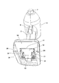
- FIG. 1 is a perspective view of a power tool body 1 according to an embodiment of the present invention and a battery pack 100 attached thereto. It is a perspective view of the battery pack 100 single body of FIG.
- FIG. 2 is a perspective view of the power tool body 1 of FIG. 1 viewed from below.
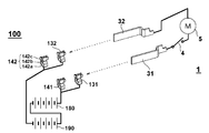
- FIG. 4 is a development view showing a connection state between a connection terminal of the electric power tool body 1 and a connection terminal of the battery pack 100.
- FIG. 3 is a block diagram for explaining the operation principle of the battery pack 100 of FIG. 1.
- 3 is a circuit diagram of the power tool body 1 and the battery pack 100.
- FIG. 3 is a circuit diagram of a charger 200 and a battery pack 100.
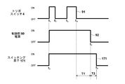
- FIG. 3 is a diagram showing an operation of a trigger switch 4 of the electric tool main body 1, an on / off state of a power source of the electric power tool main body 1, and an operation timing of a switching element 171.
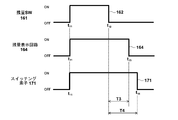
- 6 is a diagram showing the operation of the remaining amount check switch 161 of the battery pack 100 and the operation timing of the remaining amount display circuit 164 and the switching element 171.
- FIG. 1 is a perspective view for explaining a conventional low-power electric power tool body 1 and a conventional battery pack 100 mounting method.
- the electric power tool is composed of the electric power tool main body 1 and the battery pack 100 attached to the electric power tool main body 1, and drives a tip tool (not shown) or a working device (not shown) by using the rotational driving force of the motor.
- the electric tool main body 1 includes a housing 2 which is an outer frame forming an outer shape, a handle portion 3 is formed in the housing 2, and a trigger switch 4 operated by an operator is provided near the upper end of the handle portion 3.
- a tip tool mounting portion 7 is provided at the tip of the body portion of the housing 2. Below the handle portion 3, a battery pack mounting portion 10 for mounting the battery pack 100 is formed.
- the battery pack 100 can be attached to the power tool body 1 by moving it in the direction of arrow 8. Rail grooves 146 and 148 (148 are not visible in FIG. 1) are formed on both left and right sides of the battery pack 100.
- Rail grooves 146 and 148 (148 are not visible in FIG. 1) are formed on both left and right sides of the battery pack 100.
- the latch mechanism is formed in the upper rear part of the battery pack 100, in the center when viewed in the left-right direction, one large latch button 135 is provided in the left-right center, and a latch claw 136 that moves in conjunction with the latch button 135 is located from the front side to the upper side. Project to.
- the battery pack 100 When the battery pack 100 is attached to the power tool body 1, the battery pack 100 can be removed from the power tool body 1 by pressing the latch button 135 and then moving the battery pack 100 relatively in the direction opposite to the arrow 8. it can.
- the battery pack 100 accommodates a plurality of cylindrical battery cells (not visible in the figure) inside a housing 101 made of synthetic resin, and a plurality of battery cells are connected in series to have a predetermined rated voltage. You are getting the output. For example, a plurality of, for example, 10 lithium ion battery cells having a rating of 3.6V can be connected to obtain an output of 36V.
- FIG. 2 is a perspective view of the battery pack 100 according to the first embodiment of the present invention.
- the battery pack 100 is formed of a separable housing 101 made of synthetic resin, a flat lower step surface 112 is formed on the upper side of the housing 101, and an upper step surface 114 formed higher than the lower step surface 112 is formed near the center. To be done.
- a connecting portion between the lower surface 112 and the upper surface 114 is formed in a step shape, and a slot group for inserting a device-side terminal is arranged in the step portion.
- the slot group is formed with a large positive electrode terminal slot 121 and a negative electrode terminal slot 122 such as a notch that is long in the front-rear direction, and an LD terminal slot 123 and a D terminal slot 124 that are about half the length thereof. ..
- a large positive electrode terminal slot 121 and a negative electrode terminal slot 122 such as a notch that is long in the front-rear direction
- an LD terminal slot 123 and a D terminal slot 124 that are about half the length thereof. ..
- two connection terminal sets (described later in FIG. 3) that can be fitted to the device side terminals on the electric tool main body 1 side are provided.
- Only four slots are provided here, it is also possible to further provide slots and arrange the connection terminals therein, or to arrange the connection connector between the slots 123 and 124. It may be done.
- Rail grooves 146 and 148 are formed on the right side wall 147 and the left side wall 149 of the upper surface 114.
- the rail groove 146 is a recess recessed inward from the right side wall 147
- the rail groove 148 is a recess recessed inward from the left side wall 149.
- a raised portion 115 that curves upward is provided on the rear side of the upper step surface 114, and a latch button 135 is provided on the rear side surface thereof. When the latch button 135 is pushed in downward, the latch claw 136 also moves in conjunction with it.
- FIG. 3 is a perspective view of the power tool body 1 of FIG. 1 viewed from below.
- Rails 26, 28 extending parallel to the front-rear direction are formed on inner wall portions on both left and right sides of the battery pack mounting portion 10 (device-side battery pack mounting portion) of the power tool body 1 and are surrounded by the left and right rails 26, 28.
- the terminal portion 11 is provided in the space portion.
- the terminal portion 11 is manufactured by integrally molding a non-conductive material such as synthetic resin, and has a vertical surface 13 serving as an abutting surface in the mounting direction (front-back direction) and a horizontal surface 12 extending horizontally.
- the upper surface 114 and the upper surface 114 face each other.
- the terminal portion 11 is provided with a plurality of metal terminals, for example, a positive electrode input terminal 31, a negative electrode input terminal 32, an LD terminal (discharge permission signal terminal) 33, and a D terminal 34 (control signal terminal).
- the positive electrode input terminal 31 and the negative electrode input terminal 32 are formed of a metal flat plate and have a long shape in the mounting direction.
- the LD terminal 33 and the D terminal 34 are formed by a flat metal short plate.
- FIG. 4 is a perspective view showing a connection state between the connection terminals of the electric tool main body 1 and the connection terminals of the battery pack 100.
- two positive electrode output terminals 131 and 141 are arranged side by side in the mounting direction (front-back direction).
- two negative electrode output terminals 132 and 142 are arranged side by side in the mounting direction inside the slot 122 (see FIG. 2).
- the reason why two terminals are used is to eliminate poor contact with the connection terminals used on the electric tool main body 1 side and the external charger.
- the positive electrode output terminals 131 and 141 are arranged in a non-contact state in the slot 121 with a predetermined distance therebetween, and these are electrically connected by wiring.
- the negative electrode output terminals 132 and 142 are arranged in a non-contact state in the slot 122 with a predetermined distance therebetween, and these are electrically connected by wiring.
- the battery pack 100 accommodates two battery cell groups connected in series, that is, cell units 180 and 190, and the cell units 180 and 190 are connected in series.
- a rechargeable secondary battery is used as the battery cells forming the cell units 180 and 190, and is, for example, a lithium ion battery having a rated voltage of 3.6V. Therefore, the DC power having the rated voltage of 36 V is supplied between the positive electrode terminal (131, 141) and the negative electrode terminal (132, 142).
- the connection terminal group of the electric power tool body 1 includes a positive electrode input terminal 31 and a negative electrode input terminal 32.
- the DC power supplied from the battery pack 100 via the positive electrode input terminal 31 and the negative electrode input terminal 32 is supplied to the motor 5 via the trigger switch 4.
- FIG. 4 a circuit in which the main body side connection terminals (31, 32) and the motor 5 are directly connected is shown in FIG. 4 for ease of explanation, the motor 5 is driven via an inverter circuit (not shown).
- the configuration on the power tool body side is arbitrary.
- the connection terminals (31, 32) of the power tool body 1 are relatively moved as indicated by a dotted arrow, the connection terminals are inserted between the connection terminal groups (131 and 141, 132 and 142) of the battery pack 100. , An electrical connection state is established.
- the positive electrode input terminal 31 is a metal plate material bent in a crank shape, and is formed with a sufficient length so as to be fitted simultaneously with the positive electrode output terminal 131 on the front side and the positive electrode output terminal 141 on the rear side.
- the negative electrode input terminal 32 is a metal plate material bent in a crank shape, and is formed with a sufficient length so that the negative electrode output terminal 132 on the front side and the negative electrode output terminal 142 on the rear side can be simultaneously fitted. ..
- the positive electrode input terminal 31 and the negative electrode input terminal 32 are arranged so as to be plane-symmetrical, and the crank-shaped bent portion is held by being cast into the terminal portion 11 (see FIG. 3) made of synthetic resin. It The rear ends of the positive electrode input terminal 31 and the negative electrode input terminal 32 are soldered to the wiring to the motor 5 side.
- the positive electrode output terminals 131 and 141 and the negative electrode output terminals 132 and 142 have an inverted ⁇ shape when viewed from the main body side connection terminal insertion direction (direction indicated by a dotted arrow), and common parts are used for these.
- a rectangular flat plate portion 142a for fixing to a circuit board (not shown) in the battery pack 100 is formed, and the flat plate portion 142a is soldered or screwed (not shown) to the circuit board.
- Two arm portions 142b that are bent from the left and right ends of the flat plate portion 142a are formed upward from the left and right sides of the flat plate portion 142a.
- the two arm portions 142b are bent so that they approach each other as they go upward, and a terminal portion 142c is arranged at the upper end of the arm portion 142b.
- the terminal portion 142c is a substantially rectangular electrode in which the left and right terminal portions 142c are held in a non-contact state at a predetermined interval so as to be parallel to each other, and the front and rear sides thereof are separated from the opposing contact terminal portions.
- the main body side connection terminal is shaped so that it can be easily fitted from the front to the rear.
- the latch claw 136 When the latch claw 136 is inserted to a position where it comes into contact with the terminal 141, the latch claw 136 fits into a latch groove (not shown) on the battery pack 100 side. The same applies to the fitted state of the negative electrode input terminal 32 and the negative electrode output terminals 132 and 142.
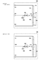
- FIG. 5 is a block diagram for explaining the operation principle of the battery pack 100.
- a total of 10 battery cells are included in the battery pack 100, but here, every 5 cells are combined into one cell unit (battery cell group), and two cell units 180 and 190 are included. Are connected in series.
- the battery cell is, for example, a cylindrical lithium ion battery having a size of 18650, and its rating is 3.6V.
- the switch 170 controllable by the control unit (control circuit) 150 is provided between the negative electrode terminal 180b of the cell unit 180 and the positive electrode terminal 190a of the cell unit 190.
- 5A shows a state of the switch 170 when the battery pack 100 is charged or when power is supplied to the electric device body by discharging.
- the switch 170 is turned on (conducting)
- a DC voltage with a rating of 36 V is output between the positive electrode output terminal 131 and the negative electrode output terminal 132.
- FIG. 5B shows a state in which the battery pack 100 is not attached to the external charger or the electric device main body or is attached to the external device (external charger or electric device main body).
- a state in which the power supply of the control unit is off (in this embodiment, this state is referred to as "normal state") is shown.
- the switch 170 is turned off, and the series connection state of the cell units 180 and 190 is canceled.
- the resistance circuit is provided in parallel with the connection circuit of the cell unit 190 and the switch 170, which is close to the ground potential.
- a resistance R having a large resistance value is provided in the resistance circuit.
- the resistor R is a resistor provided to make the positive electrode potential 180a of the cell unit 180 low when the switch 170 is turned off, and is not the purpose for flowing a substantial current through this resistor circuit.
- the resistance value of the resistor R is set to a sufficiently large value of several hundreds k to several M ⁇ to substantially block the flow of current. Therefore, although the resistance circuit of the resistance R remains connected even when the switch 170 is turned on as shown in FIG. 5 (A), there is substantially no hindrance to the charging / discharging operation of the battery pack.
- the switch 170 electrically connects or disconnects the cell units 180 and 190. Therefore, it can be realized as a device that includes mechanical components (power terminals) such as a relay switch, but if a contact-type switch is used, it is necessary to take measures against wear and sparks, and battery The life and reliability of the pack 100 may be affected. Therefore, in this embodiment, a semiconductor switching element is used as the switch 170. As the semiconductor switching element, for example, a field effect transistor (FET) or an insulated gate bipolar transistor (IGBT) can be used.
- FET field effect transistor
- IGBT insulated gate bipolar transistor
- a signal indicating the operating status of the external device is input to the control unit 150 from the external device (power tool body 1 or charger) via the D terminal (control signal terminal) 134, and the switch 170 is turned on in response to the input signal. Or switch it on. Also, the control unit 150 switches the switch 170 according to the output signal of the voltage check switch unit 160 when an operation button (not shown) of the voltage check switch unit 160 provided in the housing of the battery pack 100 is connected. Switch to the on state.
- the battery pack 100 when the battery pack 100 is not used "in a normal state", that is, when the battery pack 100 is detached from the external device and is in a single state, or when the battery pack 100 is attached, the power source of the electric device body or the external charger is In the OFF state, the series connection state of the cell unit 180 and the cell unit 190 is released by shutting off the switch 170. Therefore, it becomes easy to meet the requirements of transportation regulations. Further, it is possible to effectively suppress the ion migration phenomenon that occurs in the circuit board, the connection terminal, etc. in the battery pack 100.
- FIG. 6 is a detailed circuit diagram of the power tool body 1 and the battery pack 100 of this embodiment.
- the battery pack 100 accommodates two sets of a cell unit 180 arranged on the higher side of the voltage and a cell unit 190 arranged on the lower side, and the negative side output (ground potential 180b) of the cell unit 180 and the cell unit 190.
- a switching element 171 made of a semiconductor is interposed as a switch 170 between the positive electrode side output (positive electrode potential 190a).
- the switching element 171 is a field effect transistor (FET) having a body diode, the source is connected to the ground potential 180b of the cell unit 180, and the drain is connected to the positive potential 190a of the cell unit 190.
- the gate of the switching element 171 is connected to the drain of the switching element 163 which is a switching control unit.
- the control unit 150 includes a switching element 163 that is a switching control unit, a capacitor 172 that is a power storage unit, and a resistor 173.
- the switching element 163 stably switches the gate signal of the switching element 171 based on an external signal input from the D terminal 134.
- the switching element 163 is turned on, so that the positive potential (B +) of the cell unit 180 changes from the switching element 163 to the resistor 173 to the ground potential 180b of the cell unit 180.
- a current circuit is formed, the gate potential of the switching element 171 increases due to the potential difference between the voltages across the resistor 173, and the switching element 171 switches to the conductive state.
- the switching element 171 is turned on, a series-connected power supply circuit of the cell unit 180 and the cell unit 190 is established.
- the signal line 61 or / and the signal line 62 are high ( High voltage), and the signal is converted by a converter (not shown) including a semiconductor switching element (FET), and the D terminal 134 becomes a low signal. Therefore, the switching element 163 is maintained in the on state, and the gate signal of the switching element 171 is also maintained in the high state correspondingly, so that the switching element 171 is maintained in the on state.
- a capacitor 172 is provided in parallel with the resistor 173.
- the capacitor 172 is a delay circuit for keeping the switching element 171 in the ON state for a short period of time after the switching element 163 is switched from ON to OFF.
- the delay circuit can be composed of an electrolytic capacitor and a resistor 173, and the resistor 173 also has a function of consuming electric charge of the gate voltage of the switching element 171.
- the timing at which the switching element 171 is cut off can be delayed from about 1 to several seconds after the switching element 163 is turned off. ..
- the resistor 173 also functions to balance the consumption amounts of the cell unit 180 and the cell unit 190 when the switching element 171 is on, and if the resistance R and the resistance value of the resistor 173 are the same.
- the consumption amounts of the cell unit 180 and the cell unit 190 can be made substantially equal.
- the upper cell unit 180 is formed by connecting battery cells 181 to 185 of five lithium ion batteries and connecting them in series.
- the lower cell unit 190 is formed by connecting battery cells 191 to 195 of five lithium ion batteries and connecting them in series.
- Dedicated battery protection ICs 188 and 198 for protecting the battery cells are connected to the cell units 180 and 190, respectively.
- the battery protection IC 188 executes an overcharge protection function, an overdischarge protection function, as well as a cell balance function, a cascade connection function, and a disconnection detection function by inputting the voltages across the battery cells 181 to 185 of the cell unit 180. It is an integrated circuit which is commercially available as "protection IC for lithium ion battery". In FIG.
- the battery protection IC 188 has a built-in power supply circuit that obtains an operation power supply for the protection IC from the voltage of the cell unit 180. Therefore, one of the power supply terminals (not shown) of the battery protection IC 188 is connected to the positive potential 180a of the cell unit 180, and the other is connected to the ground potential 180b.
- the protection IC 188 grounds the LD signal 187 to the ground potential 180b to reduce the potential of the LD terminal to 0 when the voltage of at least one battery cell of the cell unit 180 falls below a predetermined value and enters an overdischarged state.
- the configuration and operation of the battery protection IC 198 are similar to those of the battery protection IC 188. Since the battery protection IC 198 obtains operating power from the voltage of the cell unit 190, one is connected to the positive potential 190a of the cell unit 190 and the other is grounded to the ground potential 190b. The protection IC 198 grounds the LD signal 197 to the ground potential 190b when the voltage of at least one battery cell of the cell unit 190 drops below a predetermined value and becomes an over-discharged state. Drop to 0.
- the voltage check switch unit 160 includes a switch (operation unit) 161, which is operated by an operator, a switching element 165, and a remaining amount display circuit 164.
- the remaining amount display circuit 164 checks the remaining amount of the battery pack 100 and displays the number of LEDs (not shown) according to the remaining amount. Therefore, a plurality of segment LED display devices and a switch 161 are provided on the side surface of the battery pack 100. When the operator operates the switch 161 to turn it on, as many LEDs as the remaining battery amount are lit during the operation and only for a few seconds after the operation state is canceled.
- the power supply of the remaining amount display circuit is obtained from the positive electrode battery 180a of the cell unit 180 connected in series and the ground potential 190b, and when the switch 161 is turned on, the cell units 180 and 190 are connected in series. In addition, the power is supplied to the circuit for displaying the remaining amount.
- the cell unit 180 and the cell unit 190 are not always connected, so some measures must be taken when checking the combined voltage of both. For example, when the battery pack 100 is removed from the external device (the power tool body 1 or the external charger), the D terminal 134 is in the high impedance state, so the switching element 163 is in the off state and the switching element 171 is also in the off state. is there. Since the combined voltage of the cell units 180 and 190 cannot be measured when the switching element 171 is off, it is necessary to turn on the switching element 171 temporarily when checking the remaining amount. Therefore, the signal line 162 is configured to be low when the switch 161 is turned on (for example, when the push button is pressed).
- a circuit for making the signal line 162 low by operating the switch 161 may be configured so that the signal line 162 is connected to the ground potential 190b when the switch 161 is operated, for example (detailed circuit description is omitted). ..
- a gate signal (low signal) having a predetermined voltage is input from the switch 161 through the signal line 162, the switching element 163 is turned on and the switching element 171 is also turned on. Then, since the cell units 180 and 190 are directly connected, the positive electrode potential (B +) 180a applied to the source terminal of the switching element 165 becomes a combined voltage of the cell units 180 and 190.
- the switching element 165 since the switching element 165 is turned on (conduction between the source and the drain) by the signal line 162 from the switch 161, the remaining amount display circuit 164 operates and the LED according to the positive electrode potential (B +) 180a and the ground potential 190b. The remaining amount is displayed by a display device (not shown). When the operation (depression) of the switch 161 is released, the switching element 163 is turned off, so that the gate voltage of the switching element 171 decreases.
- the delay circuit including the capacitor 172 and the resistor 173 can be used to continuously display a certain amount of time after the remaining amount display is turned off when the remaining amount display switch 161 is turned off, the switch can be used. The switching element 171 is turned off after a delay of several seconds occurs after the switch 161 is turned off.
- the power tool body 1 includes a power supply circuit 45.
- the power supply circuit 45 generates a reference voltage VDD that serves as an operating power supply for the control unit (device-side control unit) 50 of the power tool body 1.
- One terminal of the power supply circuit 45 is connected to the positive electrode input terminal 31 via the semiconductor switching element 43, and the other terminal is connected to the ground potential.
- the control unit 50 includes a microcomputer 51, and the microcomputer 51 monitors and controls various states in the power tool body 1.
- a DC motor 5 is provided in the power supply path between the positive input terminal 31 and the negative input terminal 32, and a trigger switch for turning on or off the rotation of the motor 5 is provided in the circuit. 4 are provided.
- a semiconductor switching element 41 and a shunt resistor 42 are inserted between the motor 5 and the negative electrode input terminal 32.
- the switching element 41 is, for example, a field effect transistor (FET), and its gate signal 63 is sent out by the microcomputer 51.
- FET field effect transistor
- the voltage across the shunt resistor 42 is input to the control unit 50 by the signal line 64 and detected by the microcomputer 51.
- the motor 5 is shown as a DC motor with a brush, but a known inverter circuit may be used to drive the three-phase brushless motor.
- An intermediate point between the positive electrode side of the motor 5 and the trigger switch 4 is connected to the D terminal 34 via a signal line 61 and a converter (not shown). Therefore, when the trigger switch 4 is pulled (turned on), the input voltage (high signal) of the positive input terminal 31 is applied to the converter (not shown). This input voltage is converted into a low signal by the converter, and a signal (low signal) indicating that the trigger switch 4 has been operated is input to the D terminal 34. When the trigger switch 4 is returned (turned off), the voltage of the signal line 61 becomes 0, so that the conversion section does not perform the conversion operation and the output side (D terminal 34) thereof is opened.
- a conversion unit provided on the input side of the switching element 43 with a device power ON signal (for example, a high signal of 5V or 3.3V) for keeping the power circuit 45 ON from the control unit 50 via the signal line 62. (Not shown).
- the conversion unit converts the signal level of the device power ON signal into a low signal, and the low signal is input to the switching element 43. Therefore, a signal (low signal) indicating that the trigger switch is on is input to the D terminal 34 when the trigger switch 4 is on, and the device power is on when the trigger switch 4 is off and the control unit 50 is running. A signal (low signal) is input.
- the device power-on signal (high signal) on the signal line 62 disappears to zero potential, and the D terminal 34 opens. From the above, by monitoring the signal level of the D terminal 134 on the battery pack 100 side, whether or not the power tool body 1 side is connected (whether the trigger switch 4 is operated) and whether it is connected or not. It is possible to easily determine whether the electric device body 1 is activated or shut down.
- the LD terminal 33 is connected to the LD terminal 133 of the battery pack 100, and the “abnormal signal” sent from the battery pack 100 is input to the control unit 50 via the LD terminal 33.
- a signal indicating whether to permit (or limit) or permit discharge from the battery pack 100 is used as the “abnormal signal”.
- the control unit 50 detects this change in the potential, sets the gate signal 63 of the switching element 41 to low to turn off the switching element 41, and supplies power to the motor 5. Stop.
- the control unit 50 does not perform stop control at the time of over-discharging based on a signal from the LD terminal of the battery pack 100, but measures the voltage between the positive electrode input terminal 31 and the negative electrode input terminal 32 in the electric tool body 1. It is also possible to provide a voltage detection circuit for performing such control and perform stop control at the time of overdischarge based on the detection value of the voltage detection circuit.
- the output of the motor 5 may be limited by controlling the on / off of the switching element 41 (known duty control) without shutting off the switching element 41 due to the disappearance of the discharge permission signal from the LD terminal.
- the control unit 50 not only monitors the voltage of the battery pack 100, but also monitors the current flowing through the motor 5, and particularly monitors the overcurrent.
- the current detection is performed by the control unit 50 by measuring the voltage across the shunt resistor 42.
- the battery pack 100 side may monitor the overcurrent, but the battery pack side overcurrent monitoring sets an average control condition (overcurrent threshold) that can be applied to a plurality of power tool bodies. Since there is no choice but to do so, it is preferable that the control unit 50 on the electric tool main body 1 side monitors the overcurrent.
- optimum control conditions higher threshold value of overcurrent
- the temperature of the motor 5 and the switching element 41 may be monitored by the control unit 50.
- a temperature sensor for example, a thermistor
- a component motor 5, switching element 41, etc.
- the switching element 41 may be controlled based on the temperature detected by the temperature sensor.
- the remaining battery level can be displayed by checking the combined voltage of the cell units 180 and 190 of the battery pack 100. Further, since the same two battery protection ICs 188 and 189 are used and the voltage check is performed using both the cell units 180 and 190 when checking the battery remaining amount, the cell units 180 and 190 consume almost the same amount.
- the LED display device (not shown) for displaying the remaining amount is turned off with a delay even after the operation of the switch 161 for remaining amount check is released, the battery pack 100 which is easy to use can be realized.
- FIG. 7 is a circuit diagram of the charger 200 and the battery pack 100 of this embodiment.
- the operation on the battery pack 100 side is the same as in FIG. That is, in the battery pack 100, when a predetermined signal (for example, a low signal) is input from the charger 200 via the D terminal 134, the switching elements 163 and 171 are turned on (conducting), and the cell units 180 and 190. Can be charged.
- a predetermined signal for example, a low signal
- the battery protection IC 188 or 198 A signal (for example, a high signal) indicating overcharge is transmitted to the control unit 250 via the LD terminals 133 and 233.
- a thermistor for detecting the temperatures of the battery cells 181 to 185 and 191 to 195 is arranged in the battery pack 100, and the output thereof is output to the controller 250 of the charger. Also good.
- the charger 200 is mainly configured by the main switch 204, the charging circuit 260, and the control unit 250.
- the control unit 250 manages the charging operation and includes a microcomputer 251.
- the microcomputer 251 executes a program that executes a known charging method such as a constant current constant voltage charging (CCCV) method that manages voltage and current, and controls the charging circuit 260 connected by the signal line 253.
- the charging circuit 260 provides a DC voltage and a DC current for charging a series connection set of 10 lithium ion battery cells using a commercial power supply of AC 100V to 240V by a power cord (not shown).
- a known circuit in which both charging currents can be adjusted by a microcomputer is used.
- the charging voltage and the charging current can be set according to the number of battery cells of the connected battery pack so that battery packs other than 10 battery cells can be charged.
- the main switch 204 can be turned on or off by the microcomputer 251.
- a constant power supply circuit for generating a DC power supply (for example, 3.3V or 5V) for operating the control unit 250 from a commercial power supply is provided, and a power supply cord (not shown) of the charger 200 is provided.
- a commercial power outlet not shown
- the charge ON signal 254 is set to high level. Then, the charging ON signal 254 is converted to a low level (low signal) via a conversion unit (not shown) provided on the input side of the D terminal 234, and the low signal is output to the D terminal 234. Then, a signal of a predetermined level (low signal) is input to the gate terminal of the switching element 163 via the D terminals 234 and 134, so that the switching element 163 becomes conductive, and the switching element 171 is also turned on (conductive). As a result, the cell units 180 and 190 are connected in series, and the total voltage of the cell units 180 and 190 is output between the positive electrode output terminal 131 and the negative electrode output terminal 132.
- the control unit 250 measures the voltage of the battery pack 100 through the signal line 255 to detect that the battery pack 100 has been attached and that the battery pack 100 is in a state to be charged, and then through the signal line 252. By turning on the main switch 204, the charging operation using the charging circuit 260 is started.
- the microcomputer 251 monitors the charging current by monitoring the voltage across the shunt resistor 261 on the signal line 262 (in the figure, two wires are bundled, but actually two wires).
- the known constant current constant voltage charging method is performed based on the voltage of the battery pack 100 measured by the microcomputer 251 on the signal line 255 and the signal line 262 and the current value during charging. That is, charging is performed by constant current control until the voltage of the battery pack 100 reaches a predetermined voltage, and then the charging current is flowed by the constant voltage control so as to maintain the predetermined voltage, and the charging current has a predetermined current value. When it reaches less than, you can stop charging. Further, the charging can be stopped based on the signals from the LD terminals 233 and 133. A signal indicating discharge permission is input to the LD terminal 233 from the battery pack 100, and is input to the microcomputer 251 of the control unit 250 via the signal line 256.
- the microcomputer 251 detects the potential drop and the control unit 250 turns off the main switch 204 to stop the charging by the charging circuit 260.
- FIG. 8 is a diagram showing the operation status 91 of the trigger switch 4 of the electric tool main body 1, the operation timing of the power supply of the control unit 50 of the electric tool main body 1, and the operation timing of the switching element 171.
- the battery voltage high signal
- the conversion unit converts the signal level into a low signal. Since a predetermined signal (low signal) is input to the gate terminal of the switching element 43 from, the power supply circuit 45 (see FIG. 6) is turned on as indicated by the operation timing 92.
- the control unit 50 see FIG.
- the control unit 50 outputs a high level signal (for example, a voltage of 3.3V) via the signal line 62.
- a high signal is converted into a low signal by a converter (not shown), and the low signal is output to the D terminal 34.
- the D terminal 134 of the battery pack 100 becomes low level, so that the switching element 163 is turned on and the switching element 171 is also turned on.
- the switching element 171 When the switching element 171 is turned on, the cell units 180 and 190 are connected in series, and a DC voltage having a rating of 36 V is output to the positive electrode output terminal 131 and the negative electrode output terminal 132 of the battery pack 100.
- the switching element 171 is not turned on when the trigger switch 4 is first pulled, in the present embodiment, the upper cell unit 180 is connected to the ground potential 190b via the resistance circuit (resistor R). Therefore, a voltage of 18 V can be supplied between the positive electrode output terminal 131 and the negative electrode output terminal 132.
- resistor R resistance circuit
- the power supply circuit 45 of the power tool body 1 is activated, even if the control unit 50 turns off the trigger switch 4 by the self-holding function, the operating state of the power supply circuit 45 is maintained for a certain period of time (eg, 10 minutes) thereafter. Maintained. Therefore, the trigger switch 4 at time t 2 is even when the trigger switch 4 again at time t 3 is turned off is drawn, the switching element 171 is kept turned on. At time t 4 the trigger switch 4 is returned (turned off), if subsequent free operation of the trigger switch 4 is, at time t 5 after the elapse of a predetermined time T1, the power supply circuit 45 of the power tool main body 1 is turned off.
- a certain period of time eg, 10 minutes
- the switching element 171 Since the switching element 171 is provided with the storage circuit of the capacitor 172 on the gate side, even if the gate signal of the switching element 171 (the drain output of the switching element 163) disappears, the switching element 171 is turned on by the capacitor 172 only for the time T2. Is maintained, and the switching element 171 is turned off at time t 6 .
- FIG. 9 is a diagram showing an operation 162 of the remaining amount check switch 161 of the battery pack 100 and operation timings of the remaining amount display circuit 164 and the switching element 171.
- the remaining amount display circuit 164 is turned on, the switching element 163 is turned on, and the switching element 173 is also turned on.
- the switching element 171 is turned on, the cell units 180 and 190 are connected in series, the remaining amount according to the total voltage of the cell units 180 and 190 is displayed, and is displayed until time t 13 .
- the remaining amount checking switch 161 at time t 12 is returned (turned off) will be not immediately turn off to the returned time t 12, the predetermined time T3 has elapsed continue the remaining amount display up to time t 13.
- the display is displayed for the time T3 or more, so that a power checker that is easy to see can be realized.
- the remaining amount checking switch 161 at time t 12 is turned off, because the power storage circuit is provided by capacitor 172 to the gate of the switching element 171, the capacitor 172 from the drain output of the switching element 163 is lost until the accumulated charge is lost, is maintained oN state of the switching device 171 by the time T4, the switching element 171 is turned off at time t 14.
- the battery pack 100 in the battery pack 100, a mechanism is realized in which each cell unit is connected during operation and the cell units 180 and 190 are electrically separated during non-operation.
- the number of battery cells connected in series can be increased, and in realizing the battery pack 100 having a higher voltage than before, it can be configured to satisfy the restriction of transportation regulation. Further, since the risk of ion migration of the circuit board in the battery pack 100 can be reduced, the battery pack 100 having high reliability and long life can be realized.
- the main device side is not limited to the electric power tool, and may be any electric device as long as it is a device that operates the battery pack as a main power source or an auxiliary power source.
- an additional switch means such as an FET is provided between the resistor R and the ground potential 190b so that the switching element 171 is turned on.
- the additional switch means may be turned off in conjunction with In this case, the resistance circuit formed by the resistor R disconnects the parallel connection with the cell unit 190 during charging and discharging.
- SYMBOLS 1 Electric tool main body, 2 ... Housing, 3 ... Handle part, 4 ... Trigger switch, 5 ... Motor, 7 ... Tip tool mounting part, 8 ... (Battery pack) mounting direction, 10 ... Battery pack mounting part, 11 ... Terminal part, 12 ... Horizontal surface, 13 ... Vertical surface, 26, 28 ... Rail, 31 ... Positive electrode input terminal, 32 ... Negative electrode input terminal, 33 ... LD terminal, 34 ... D terminal, 41 ... Switching element, 42 ... Shunt resistor, 43 ... Switching element, 45 ... Power supply circuit, 50 ... Control part, 61, 62 ... Signal line, 63 ... Gate signal, 64 ... Signal line, 100 ...
- Battery pack 101 ... Housing, 112 ... Lower surface, 114 ... Upper surface , 115 ... Protuberances, 121 ... Positive electrode terminal slots, 122 ... Negative electrode terminal slots, 123 ... LD terminal slots, 124 ... D terminal slots, 131 ... Positive electrode output terminals, 1 2 ... Negative output terminal, 133 ... LD terminal, 134 ... D terminal, 135 ... Latch button, 136 ... Latch claw, 141 ... Positive electrode output terminal, 142 ... Negative output terminal, 142a ... Flat plate part, 142b ... Arm part, 142c ... Terminal part, 146, 148 ... Rail groove, 147 ... Right side wall, 149 ... Left side wall, 150 ...
Landscapes
- Engineering & Computer Science (AREA)
- Mechanical Engineering (AREA)
- Power Engineering (AREA)
- Manufacturing & Machinery (AREA)
- Chemical & Material Sciences (AREA)
- Chemical Kinetics & Catalysis (AREA)
- Electrochemistry (AREA)
- General Chemical & Material Sciences (AREA)
- Charge And Discharge Circuits For Batteries Or The Like (AREA)
- Secondary Cells (AREA)
- Battery Mounting, Suspending (AREA)
- Portable Power Tools In General (AREA)
Abstract
Le but de la présente invention est d'obtenir un bloc-batterie qui est conçu pour transporter des réglementations et capable de fournir une sortie élevée. Le bloc-batterie est pourvu d'unités de cellule 180 et 190, d'un élément de commutation 171 connecté en série entre les unités de cellule, et d'un circuit de commande (élément de commutation 163) pour faire fonctionner l'élément de commutation 171. Le bloc-batterie est configuré de telle sorte que, lorsqu'il n'est pas en fonctionnement, les unités de cellule 180 et 190 sont électriquement séparées l'une de l'autre. Lorsqu'un signal d'alimentation électrique de l'appareil externe a été transmis par l'intermédiaire d'une borne D 134, le circuit de commande amène l'élément de commutation 171 à conduire, moyennant quoi une tension de la connexion en série des unités de cellule 180 et 190 est délivrée à une borne de sortie de pôle positif 133 et à une borne de sortie de pôle négatif 134. Lorsque le signal d'alimentation électrique de l'appareil externe est perdu, l'élément de commutation 171 est éteint après un court délai de retard dû à un condensateur 172.
Priority Applications (1)
| Application Number | Priority Date | Filing Date | Title |
|---|---|---|---|
| JP2020553852A JP7056755B2 (ja) | 2018-10-30 | 2019-10-25 | 電池パック及びそれを用いた電気機器 |
Applications Claiming Priority (2)
| Application Number | Priority Date | Filing Date | Title |
|---|---|---|---|
| JP2018203874 | 2018-10-30 | ||
| JP2018-203874 | 2018-10-30 |
Publications (1)
| Publication Number | Publication Date |
|---|---|
| WO2020090670A1 true WO2020090670A1 (fr) | 2020-05-07 |
Family
ID=70462373
Family Applications (1)
| Application Number | Title | Priority Date | Filing Date |
|---|---|---|---|
| PCT/JP2019/041958 Ceased WO2020090670A1 (fr) | 2018-10-30 | 2019-10-25 | Bloc-batterie et appareil électrique l'utilisant |
Country Status (2)
| Country | Link |
|---|---|
| JP (1) | JP7056755B2 (fr) |
| WO (1) | WO2020090670A1 (fr) |
Cited By (1)
| Publication number | Priority date | Publication date | Assignee | Title |
|---|---|---|---|---|
| CN114865210A (zh) * | 2022-03-08 | 2022-08-05 | 江苏苏美达五金工具有限公司 | 一种电压自动转换电池组 |
Citations (6)
| Publication number | Priority date | Publication date | Assignee | Title |
|---|---|---|---|---|
| JP2008061363A (ja) * | 2006-08-30 | 2008-03-13 | Gs Yuasa Corporation:Kk | 電池パックの充電システム |
| JP2009261230A (ja) * | 2008-03-25 | 2009-11-05 | Tokyo Electric Power Co Inc:The | 電気自動車用充電システム |
| JP2012029491A (ja) * | 2010-07-26 | 2012-02-09 | Nissan Motor Co Ltd | 電動車両システム |
| WO2014162645A1 (fr) * | 2013-04-01 | 2014-10-09 | ソニー株式会社 | Dispositif et système de stockage d'électricité et véhicule électrique |
| WO2016152025A1 (fr) * | 2015-03-26 | 2016-09-29 | 三洋電機株式会社 | Bloc de batteries et dispositif de fabrication s'y rapportant |
| JP2018078672A (ja) * | 2016-11-07 | 2018-05-17 | 株式会社豊田自動織機 | 電池モジュール及び電池パック |
Family Cites Families (1)
| Publication number | Priority date | Publication date | Assignee | Title |
|---|---|---|---|---|
| US11824169B2 (en) * | 2016-10-31 | 2023-11-21 | Koki Holdings Co., Ltd. | Battery pack, electrical device using battery pack, and electrical device system |
-
2019
- 2019-10-25 WO PCT/JP2019/041958 patent/WO2020090670A1/fr not_active Ceased
- 2019-10-25 JP JP2020553852A patent/JP7056755B2/ja active Active
Patent Citations (6)
| Publication number | Priority date | Publication date | Assignee | Title |
|---|---|---|---|---|
| JP2008061363A (ja) * | 2006-08-30 | 2008-03-13 | Gs Yuasa Corporation:Kk | 電池パックの充電システム |
| JP2009261230A (ja) * | 2008-03-25 | 2009-11-05 | Tokyo Electric Power Co Inc:The | 電気自動車用充電システム |
| JP2012029491A (ja) * | 2010-07-26 | 2012-02-09 | Nissan Motor Co Ltd | 電動車両システム |
| WO2014162645A1 (fr) * | 2013-04-01 | 2014-10-09 | ソニー株式会社 | Dispositif et système de stockage d'électricité et véhicule électrique |
| WO2016152025A1 (fr) * | 2015-03-26 | 2016-09-29 | 三洋電機株式会社 | Bloc de batteries et dispositif de fabrication s'y rapportant |
| JP2018078672A (ja) * | 2016-11-07 | 2018-05-17 | 株式会社豊田自動織機 | 電池モジュール及び電池パック |
Cited By (1)
| Publication number | Priority date | Publication date | Assignee | Title |
|---|---|---|---|---|
| CN114865210A (zh) * | 2022-03-08 | 2022-08-05 | 江苏苏美达五金工具有限公司 | 一种电压自动转换电池组 |
Also Published As
| Publication number | Publication date |
|---|---|
| JPWO2020090670A1 (ja) | 2021-11-04 |
| JP7056755B2 (ja) | 2022-04-19 |
Similar Documents
| Publication | Publication Date | Title |
|---|---|---|
| CN100442630C (zh) | 用于电动工具的可充电电池组件 | |
| CN101145686B (zh) | 电动工具 | |
| US9337677B2 (en) | Electric power tool powered by battery pack and adapter therefor | |
| KR100193736B1 (ko) | 배터리 보호 기능을 갖는 배터리 팩 | |
| CN105322611B (zh) | 电池组以及用于控制电池组的方法 | |
| JP5275176B2 (ja) | 電池パックおよびその機能停止方法 | |
| US8378624B2 (en) | Battery charger | |
| JP4011563B2 (ja) | バッテリ保護のための方法およびシステム | |
| EP2221937B1 (fr) | Circuit de charge intégré pour batterie secondaire et batterie secondaire dotée du circuit de charge intégré | |
| US20200212505A1 (en) | Battery pack and electric apparatus using battery pack | |
| CN101047321B (zh) | 锂电池组件及电动工具 | |
| US10199844B2 (en) | Power-supplying device | |
| CN1967964A (zh) | 用于电动工具的可充电电池组件 | |
| CN104969408B (zh) | 电池包及电气设备 | |
| CN104953685A (zh) | 电池充电器 | |
| AU2014100127A4 (en) | Mobile electric device with at least two lithium-ion batteries and arrangement of two such batteries electrically connected in series | |
| CN104425793A (zh) | 电池组、电动工具和电池充电器 | |
| JP2009095162A (ja) | 電池パックおよび電池パックを用いた電動工具 | |
| JP2018062013A (ja) | 電動作業機 | |
| JP7375897B2 (ja) | 電気機器 | |
| KR102609865B1 (ko) | 배터리 팩 및 이를 포함하는 전자 장치 | |
| US20240266619A1 (en) | Battery pack and electric device | |
| JP7056755B2 (ja) | 電池パック及びそれを用いた電気機器 | |
| JP2013105726A (ja) | 電池パックおよび電池カバー | |
| JP2001339866A (ja) | 二次電池を内蔵する電気機器 |
Legal Events
| Date | Code | Title | Description |
|---|---|---|---|
| 121 | Ep: the epo has been informed by wipo that ep was designated in this application |
Ref document number: 19877621 Country of ref document: EP Kind code of ref document: A1 |
|
| ENP | Entry into the national phase |
Ref document number: 2020553852 Country of ref document: JP Kind code of ref document: A |
|
| NENP | Non-entry into the national phase |
Ref country code: DE |
|
| 122 | Ep: pct application non-entry in european phase |
Ref document number: 19877621 Country of ref document: EP Kind code of ref document: A1 |