WO2020090742A1 - Fibre optique - Google Patents
Fibre optique Download PDFInfo
- Publication number
- WO2020090742A1 WO2020090742A1 PCT/JP2019/042179 JP2019042179W WO2020090742A1 WO 2020090742 A1 WO2020090742 A1 WO 2020090742A1 JP 2019042179 W JP2019042179 W JP 2019042179W WO 2020090742 A1 WO2020090742 A1 WO 2020090742A1
- Authority
- WO
- WIPO (PCT)
- Prior art keywords
- optical fiber
- refractive index
- fiber according
- diameter
- less
- Prior art date
- Legal status (The legal status is an assumption and is not a legal conclusion. Google has not performed a legal analysis and makes no representation as to the accuracy of the status listed.)
- Ceased
Links
Images



Classifications
-
- G—PHYSICS
- G02—OPTICS
- G02B—OPTICAL ELEMENTS, SYSTEMS OR APPARATUS
- G02B6/00—Light guides; Structural details of arrangements comprising light guides and other optical elements, e.g. couplings
- G02B6/02—Optical fibres with cladding with or without a coating
- G02B6/036—Optical fibres with cladding with or without a coating core or cladding comprising multiple layers
-
- G—PHYSICS
- G02—OPTICS
- G02B—OPTICAL ELEMENTS, SYSTEMS OR APPARATUS
- G02B6/00—Light guides; Structural details of arrangements comprising light guides and other optical elements, e.g. couplings
- G02B6/02—Optical fibres with cladding with or without a coating
- G02B6/02395—Glass optical fibre with a protective coating, e.g. two layer polymer coating deposited directly on a silica cladding surface during fibre manufacture
-
- C—CHEMISTRY; METALLURGY
- C03—GLASS; MINERAL OR SLAG WOOL
- C03C—CHEMICAL COMPOSITION OF GLASSES, GLAZES OR VITREOUS ENAMELS; SURFACE TREATMENT OF GLASS; SURFACE TREATMENT OF FIBRES OR FILAMENTS MADE FROM GLASS, MINERALS OR SLAGS; JOINING GLASS TO GLASS OR OTHER MATERIALS
- C03C13/00—Fibre or filament compositions
- C03C13/04—Fibre optics, e.g. core and clad fibre compositions
- C03C13/045—Silica-containing oxide glass compositions
-
- C—CHEMISTRY; METALLURGY
- C03—GLASS; MINERAL OR SLAG WOOL
- C03C—CHEMICAL COMPOSITION OF GLASSES, GLAZES OR VITREOUS ENAMELS; SURFACE TREATMENT OF GLASS; SURFACE TREATMENT OF FIBRES OR FILAMENTS MADE FROM GLASS, MINERALS OR SLAGS; JOINING GLASS TO GLASS OR OTHER MATERIALS
- C03C25/00—Surface treatment of fibres or filaments made from glass, minerals or slags
- C03C25/10—Coating
- C03C25/104—Coating to obtain optical fibres
- C03C25/1065—Multiple coatings
-
- C—CHEMISTRY; METALLURGY
- C03—GLASS; MINERAL OR SLAG WOOL
- C03C—CHEMICAL COMPOSITION OF GLASSES, GLAZES OR VITREOUS ENAMELS; SURFACE TREATMENT OF GLASS; SURFACE TREATMENT OF FIBRES OR FILAMENTS MADE FROM GLASS, MINERALS OR SLAGS; JOINING GLASS TO GLASS OR OTHER MATERIALS
- C03C3/00—Glass compositions
- C03C3/04—Glass compositions containing silica
- C03C3/06—Glass compositions containing silica with more than 90% silica by weight, e.g. quartz
-
- G—PHYSICS
- G02—OPTICS
- G02B—OPTICAL ELEMENTS, SYSTEMS OR APPARATUS
- G02B6/00—Light guides; Structural details of arrangements comprising light guides and other optical elements, e.g. couplings
- G02B6/02—Optical fibres with cladding with or without a coating
- G02B6/02004—Optical fibres with cladding with or without a coating characterised by the core effective area or mode field radius
- G02B6/02009—Large effective area or mode field radius, e.g. to reduce nonlinear effects in single mode fibres
-
- G—PHYSICS
- G02—OPTICS
- G02B—OPTICAL ELEMENTS, SYSTEMS OR APPARATUS
- G02B6/00—Light guides; Structural details of arrangements comprising light guides and other optical elements, e.g. couplings
- G02B6/02—Optical fibres with cladding with or without a coating
- G02B6/02004—Optical fibres with cladding with or without a coating characterised by the core effective area or mode field radius
- G02B6/02009—Large effective area or mode field radius, e.g. to reduce nonlinear effects in single mode fibres
- G02B6/02014—Effective area greater than 60 square microns in the C band, i.e. 1530-1565 nm
Definitions
- the present invention relates to an optical fiber.
- the small-diameter optical fiber is an optical fiber in which a portion mainly made of glass has a small diameter, and has a small clad diameter.
- a thin optical fiber includes a thin outer diameter including a coating portion formed so as to cover the outer periphery of the cladding portion due to the thinning of the cladding diameter.
- Non-Patent Document 1 a configuration has been disclosed in which the relative refractive index difference between the core portion and the cladding portion is increased (Non-Patent Document 1). Since the optical fiber of Non-Patent Document 1 has a high relative refractive index difference, its characteristics are ITU-T (International Telecommunication Union) G.264. It does not comply with the standard of a standard single-mode optical fiber (hereinafter, referred to as G.652 standard) defined by 652. Further, as a small-diameter optical fiber, a configuration is disclosed in which a trench layer having a relative refractive index difference of ⁇ 0.08% or more is provided (Patent Document 1). The optical fiber of Patent Document 1 is G.
- Patent Document 2 a configuration is disclosed in which a primary coat layer and a secondary coat layer are provided as coating portions, and the secondary coating layer is 25 ⁇ m or less (Patent Document 2).
- the optical fiber of Patent Document 2 has a fiber diameter of 125 ⁇ m, but the diameter is reduced by reducing the coating thickness.
- Patent Document 3 discloses a configuration for suppressing microbend loss in an optical fiber having a relatively large effective core area (Aeff) of 130 ⁇ m 2 or more.
- the primary coating layer has an outer diameter of 185 ⁇ m or more and 220 ⁇ m or less
- the secondary coating layer has an outer diameter of 225 ⁇ m or more and 260 ⁇ m or less.
- Patent Document 1 Japanese Unexamined Patent Publication No.
- the cladding diameter when the cladding diameter is reduced, for example, 100 ⁇ m or less, the reduction in diameter affects the microbend loss of the optical fiber, and the microbend loss increases. Conceivable.
- the increase in microbend loss is due to G.G. This is important in an optical fiber having a characteristic conforming to the 652 standard or a characteristic close thereto.
- the present invention has been made in view of the above, and an object thereof is to provide an optical fiber having a small diameter and suppressing an increase in microbend loss.
- an optical fiber in order to solve the above-mentioned problems and achieve the object, an optical fiber according to an aspect of the present invention, a core portion made of silica-based glass, covers the outer periphery of the core portion, from the maximum refractive index of the core portion.
- the cladding part has an outer diameter of 100 ⁇ m or less, and the relative refractive index difference ⁇ 1 of the core part is Is 0.5% or less, and the thickness of the coating portion is 10 ⁇ m or more.
- the coating portion has a primary coating layer located on the cladding portion side and a secondary coating layer located on the outer peripheral side of the primary coating layer, and the primary coating layer Is 10 ⁇ m or more in thickness.
- the optical fiber according to one aspect of the present invention is characterized in that the thickness of the primary coating layer is 30 ⁇ m or less.
- the optical fiber according to one aspect of the present invention is characterized in that the outer diameter of the clad portion is 95 ⁇ m or less.
- the optical fiber according to one aspect of the present invention has a microbend loss at a wavelength of 1550 nm that is ITU-T. It is 10 times or less than the microbend loss at a wavelength of 1550 nm of a standard optical fiber having a characteristic conforming to the standard defined by 652 and having a resin coating portion having a thickness of 62.5 ⁇ m on the outer circumference of a clad portion.
- the optical fiber according to one aspect of the present invention is characterized in that the microbend loss is a value measured by a polishing paper method.
- the optical fiber according to one aspect of the present invention is characterized by having a step type refractive index profile.
- the optical fiber according to one aspect of the present invention is characterized by having a W-shaped refractive index profile.
- the optical fiber according to one aspect of the present invention is characterized by having a trench type refractive index profile.
- the optical fiber according to one aspect of the present invention is characterized in that the mode field diameter at a wavelength of 1310 nm is in the range of 8.0 ⁇ m to 10.0 ⁇ m.
- the optical fiber according to one aspect of the present invention is characterized in that the mode field diameter at a wavelength of 1550 nm is 9 ⁇ m or more.
- the optical fiber according to one aspect of the present invention is characterized in that the relative refractive index difference ⁇ 1 of the core portion is 0.25% or more.
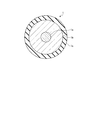
- FIG. 1 is a schematic sectional view of an optical fiber according to an embodiment.
- FIG. 2A is a schematic diagram of a step-type refractive index profile that can be used in the optical fiber according to the embodiment.
- FIG. 2B is a schematic diagram of a W-shaped refractive index profile that can be used in the optical fiber according to the embodiment.
- FIG. 2C is a schematic diagram of a trench type refractive index profile that can be used in the optical fiber according to the embodiment.
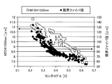
- FIG. 3 is a diagram showing an example of the relationship between the center core ⁇ and the mode field diameter or the limit fiber diameter.
- FIG. 4 is a diagram showing an example of the relationship between the effective core area and the normalized microbend loss.
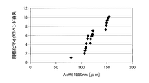
- FIG. 5 is a diagram showing an example of the relationship between the primary thickness and the normalized microbend loss.
- the cutoff wavelength means ITU-T G.264.
- other terms not specifically defined in this specification are described in G. 650.1 and G.I.
- the definition and measurement method in 650.2 shall be followed.
- FIG. 1 is a schematic sectional view of an optical fiber according to an embodiment.
- the optical fiber 1 includes a core portion 1a located substantially at the center, a clad portion 1b that covers the outer periphery of the core portion 1a, and a coating portion 1c that covers the outer periphery of the clad portion 1b.
- Both the core part 1a and the clad part 1b are made of silica glass.
- the core portion 1a is made of quartz glass to which a dopant for adjusting the refractive index such as germanium (Ge) or fluorine (F) is added.
- the clad portion 1b has a refractive index lower than the maximum refractive index of the core portion 1a.
- the clad portion 1b is made of, for example, pure silica glass containing no dopant for adjusting the refractive index.
- the outer diameter (clad diameter) of the clad portion 1b is 100 ⁇ m or less, preferably less than 100 ⁇ m.
- the diameter is smaller than the cladding diameter of the single mode optical fiber conforming to the 652 standard, which is about 125 ⁇ m.
- the clad diameter is more preferably 95 ⁇ m or less from the viewpoint of reducing the diameter.
- G A single mode optical fiber compliant with the 652 standard may be referred to as a standard SMF as a standard optical fiber.
- a standard SMF usually has a resin coating portion having a thickness of about 62.5 ⁇ m on the outer periphery of the clad portion. Therefore, the outer diameter of the resin coating portion is about 250 ⁇ m.
- the optical fiber 1 has a refractive index profile as shown in FIGS. 2A, 2B, and 2C, for example.
- 2A, 2B, and 2C each show a refractive index profile in the radial direction from the central axis of the core portion 1a of the optical fiber 1.
- FIG. 2A shows a step type refractive index profile.
- profile P11 shows the refractive index profile of the core part 1a
- profile P12 shows the refractive index profile of the clad part 1b.
- the refractive index profile is indicated by the relative refractive index difference with respect to the cladding portion 1b.
- the diameter of the core portion 1a is 2a
- the relative refractive index difference of the core portion 1a with respect to the cladding portion 1b is ⁇ 1.
- FIG. 2B shows a so-called W-shaped refractive index profile.
- profile P21 shows the refractive index profile of the core part 1a
- profile P22 shows the refractive index profile of the clad part 1b.
- the core portion 1a surrounds the center core portion having a diameter of 2a and the outer periphery of the center core portion, and the refractive index is smaller than the refractive index of the clad portion and the inner diameter is 2a and the outer diameter is 2b. It consists of a depressed layer.
- the relative refractive index difference of the center core portion with respect to the clad portion 1b is ⁇ 1.
- the relative refractive index difference of the depressed layer with respect to the clad portion 1b is ⁇ 2.
- FIG. 2C shows a so-called trench type refractive index profile.
- profile P31 shows the refractive index profile of the core part 1a
- profile P32 shows the refractive index profile of the clad part 1b.
- the core portion 1a surrounds the center core portion having a diameter of 2a and the outer periphery of the center core portion, and the refractive index is smaller than the refractive index of the center core portion and the inner diameter is 2a and the outer diameter is 2b. It is composed of an intermediate layer and a trench layer surrounding the outer periphery of the intermediate layer and having a refractive index smaller than that of the cladding portion and having an inner diameter of 2b and an outer diameter of 2c.
- the relative refractive index difference of the center core portion with respect to the intermediate layer is ⁇ 1.
- the relative refractive index difference of the intermediate layer with respect to the clad portion 1b is ⁇ 2. It should be noted that ⁇ 2 is usually set to 0% or in the vicinity thereof, for example, in a range between ⁇ 0.2% and 0.2%.
- the relative refractive index difference of the trench layer with respect to the clad portion 1b is ⁇ 3.
- the coating portion 1c is made of resin, for example, and has a function of protecting the glass portion of the optical fiber 1.
- the coating portion 1c is made of, for example, a UV curable resin or the like and has a layer structure of one layer or two or more layers.
- the coating portion 1c includes a primary coating layer located on the cladding portion side and a secondary coating layer located on the outer peripheral side of the primary coating layer.
- the UV curable resin used for the coating portion 1c include urethane acrylate-based, polybutadiene acrylate-based, epoxy acrylate-based, silicone acrylate-based, polyester acrylate-based, etc. Not limited.
- the coating part 1c has a Young's modulus of about 10 to 800 MPa in the case of a one-layer structure, and 200 MPa in the present embodiment.
- the Young's modulus of the primary coating layer is about 0.2 to 1.5 MPa, which is 0.5 MPa in this embodiment.
- the Young's modulus of the secondary coating layer is about 500 to 2000 MPa, and is 1000 MPa in this embodiment.
- the thickness of the coating portion 1c is 10 ⁇ m or more, and particularly in the case of a two-layer structure, the thickness of the primary coating layer is 10 ⁇ m or more.
- the optical fiber 1 according to the present embodiment has the above-described configuration, so that the cladding portion 1b has a small diameter of 100 ⁇ m or less and the increase in microbend loss is suppressed. Therefore, the optical fiber 1 is suitable for realizing a high-density optical fiber cable.
- the following is a specific explanation.
- the present inventors have conducted the following studies in order to realize a small-diameter optical fiber in which an increase in microbend loss is suppressed.
- leakage loss is small in order to realize a small diameter optical fiber.
- the leakage loss is preferably suppressed to 0.001 dB / km or less at a wavelength of 1625 nm.
- the mode field diameter (MFD) of the small diameter optical fiber at the wavelength of 1550 nm is preferably 9 ⁇ m or more. Therefore, in the case of the three types of refractive index profiles illustrated in FIG. 2, simulation calculation was performed for various combinations of parameters related to the refractive index profile shown in FIG. 2, and the optical characteristics of the optical fiber in each combination were calculated.
- the minimum cladding diameter (limit fiber diameter) at which the leakage loss can be 0.001 dB / km or less at a wavelength of 1625 nm and the MFD at a wavelength of 1550 nm were investigated by simulation calculation. It can be said that the smaller the limit fiber diameter, the more suitable is the combination of parameters for reducing the diameter of the optical fiber.
- Table 1 shows the range of values used in the simulation calculation for the parameters ⁇ 1, ⁇ 2, ⁇ 3, b / a, c / a shown in FIG. 2a is a value within the range of 6.5 ⁇ m to 10 ⁇ m.
- FIG. 3 is a diagram showing an example of the relationship between the center core ⁇ and the MFD or the limit fiber diameter based on the above calculation result.
- the center core ⁇ means ⁇ 1.
- FIG. 3 only data whose cutoff wavelength is 1530 nm or less in the result of simulation calculation is plotted.
- the contours of the data points are omitted in the overlapping portions.
- the legend is not distinguished by the refractive index profile, it can be said that the tendency does not depend on the refractive index profile.
- the center core ⁇ ( ⁇ 1) be 0.5% or less regardless of the refractive index profile.
- the center core ⁇ is preferably 0.25% or more, and when the limit fiber diameter is 95 ⁇ m or less, the center core ⁇ is 0.3% or more.
- ⁇ 1 is preferably 0.5% or less, preferably 0.25% or more, and more preferably 0.3% or more.
- ⁇ 1 is preferably 0.25% or more from the viewpoint that the MFD of the small-diameter optical fiber at the wavelength of 1550 nm is about 10.5 ⁇ m or less to reduce the difference from the MFD of the standard SMF.
- the following optical fibers can be exemplified as the optical fibers for which the MFDs of the small-diameter optical fibers are brought close to each other to improve the compatibility. That is, G.
- An optical fiber conforming to the 657 standard (so-called bend resistant optical fiber) or the like is used. Therefore, as a characteristic of the small-diameter optical fiber, it is also preferable that the MFD at a wavelength of 1310 nm is in the range of 8.0 ⁇ m to 10.0 ⁇ m.
- the MFD at a wavelength of 1310 nm is in the range of 8.6 ⁇ m to 9.5 ⁇ m.
- the transmission loss of an optical fiber increases when the optical fiber cable is used.
- the increase amount of the transmission loss at this time is closely related to the microbend loss, and the increase amount is large when the microbend loss is large.
- FIG. 4 is a diagram showing an example of the relationship between standardized microbend loss and Aeff at a wavelength of 1550 nm of standard SMF and some Aeff expanded optical fibers.
- the standardized microbend loss is a value obtained by standardizing the microbend loss of a certain optical fiber with the microbend loss of the standard SMF.
- the Aeff of the standard SMF is about 80 ⁇ m 2
- the standardized microbend loss of the standard SMF itself is 1.
- the standard SMF is assumed to have a resin coating part having a two-layer structure with a thickness of about 62.5 ⁇ m on the outer periphery of the clad part.
- the normalized microbend loss is preferably 10 or less, and more preferably 5 or less. That is, the microbend loss of the small-diameter optical fiber is preferably 10 times or less that of the standard SMF, and more preferably 5 times or less.
- the microbend loss shown in FIG. 4 is measured by the fixed diameter drum method (a kind of abrasive paper method) defined by JIS C6823: 2010_10.
- the refractive index profile was set to step type, W type, or trench type, and design parameters such as ⁇ 1 in each profile were optimized by simulation calculation.
- optimization means G. 652 standard, G.I. 654 standard, or G. It means optimizing the compatibility with the optical fiber defined in the 657 standard.
- the coating portion had a two-layer structure including a primary coating layer and a secondary coating layer.
- the Young's modulus of the primary coating layer was 0.5 MPa, and the Young's modulus of the secondary coating layer was 1000 MPa.
- the thickness of the secondary coating layer was 120 ⁇ m, and the thickness of the primary coating layer was different values in the range of 5 ⁇ m to 30 ⁇ m. Then, the microbend loss of these manufactured small diameter optical fibers was measured by the fixed drum diameter method.
- FIG. 5 is a diagram showing an example of the relationship between the primary thickness and the normalized microbend loss in the above measurement.
- the primary thickness is the thickness of the primary coating layer.
- the primary thickness needs to be 10 ⁇ m or more. That is, the thickness of the coating portion needs to be 10 ⁇ m or more. If the primary thickness is 30 ⁇ m, the normalized microbend loss can be set to about 1, so the primary thickness may be 30 ⁇ m or less. It was also confirmed that there is not much correlation between the thickness of the secondary coating layer and the normalized microbend loss, and the primary thickness is important.
- the step type, the W type, and the trench type are exemplified as the refractive index profile, but other refractive index profiles such as the segment core type and the W + side core type can also be applied.
- the present invention is not limited to the above embodiment.
- the present invention also includes those configured by appropriately combining the above-described components. Further, further effects and modified examples can be easily derived by those skilled in the art. Therefore, the broader aspects of the present invention are not limited to the above embodiments, and various modifications can be made.
- optical fiber according to the present invention can be suitably used in the field of optical communication such as datacom and telecom.
- Optical fiber 1a Core part 1b Cladding part 1c Coating part P11, P12, P21, P22, P31, P32 Profile
Landscapes
- Physics & Mathematics (AREA)
- Chemical & Material Sciences (AREA)
- Optics & Photonics (AREA)
- Life Sciences & Earth Sciences (AREA)
- General Physics & Mathematics (AREA)
- Engineering & Computer Science (AREA)
- Chemical Kinetics & Catalysis (AREA)
- General Chemical & Material Sciences (AREA)
- Geochemistry & Mineralogy (AREA)
- Materials Engineering (AREA)
- Organic Chemistry (AREA)
- General Life Sciences & Earth Sciences (AREA)
- Optical Fibers, Optical Fiber Cores, And Optical Fiber Bundles (AREA)
- Surface Treatment Of Glass Fibres Or Filaments (AREA)
Abstract
La présente invention vise à obtenir une fibre optique de petit diamètre et dans laquelle une augmentation de la perte de microcourbure est supprimée. La fibre optique comprend : une partie cœur qui est constituée de verre à base de silice ; une partie gaine qui recouvre la périphérie extérieure de la partie cœur et qui est constituée de verre à base de silice dont l'indice de réfraction est inférieur à l'indice de réfraction maximal de la partie cœur ; et une partie revêtement qui recouvre la périphérie externe de la partie gaine, le diamètre externe de la partie gaine étant inférieur ou égal à 100 µm, la différence d'indice de réfraction relative Δ1 de la partie cœur étant inférieure ou égale à 0,5 %, et l'épaisseur de la partie revêtement étant de 10 µm ou plus.
Priority Applications (3)
| Application Number | Priority Date | Filing Date | Title |
|---|---|---|---|
| EP19880435.3A EP3876010A4 (fr) | 2018-10-30 | 2019-10-28 | Fibre optique |
| JP2020553894A JP7407729B2 (ja) | 2018-10-30 | 2019-10-28 | 光ファイバ |
| US17/232,221 US11624871B2 (en) | 2018-10-30 | 2021-04-16 | Optical fiber |
Applications Claiming Priority (2)
| Application Number | Priority Date | Filing Date | Title |
|---|---|---|---|
| JP2018-204298 | 2018-10-30 | ||
| JP2018204298 | 2018-10-30 |
Related Child Applications (1)
| Application Number | Title | Priority Date | Filing Date |
|---|---|---|---|
| US17/232,221 Continuation US11624871B2 (en) | 2018-10-30 | 2021-04-16 | Optical fiber |
Publications (1)
| Publication Number | Publication Date |
|---|---|
| WO2020090742A1 true WO2020090742A1 (fr) | 2020-05-07 |
Family
ID=70464445
Family Applications (1)
| Application Number | Title | Priority Date | Filing Date |
|---|---|---|---|
| PCT/JP2019/042179 Ceased WO2020090742A1 (fr) | 2018-10-30 | 2019-10-28 | Fibre optique |
Country Status (4)
| Country | Link |
|---|---|
| US (1) | US11624871B2 (fr) |
| EP (1) | EP3876010A4 (fr) |
| JP (1) | JP7407729B2 (fr) |
| WO (1) | WO2020090742A1 (fr) |
Families Citing this family (3)
| Publication number | Priority date | Publication date | Assignee | Title |
|---|---|---|---|---|
| US11803007B2 (en) * | 2019-11-08 | 2023-10-31 | Fujikura Ltd. | Optical fiber |
| US20230296828A1 (en) * | 2020-07-06 | 2023-09-21 | Nippon Telegraph And Telephone Corporation | Optical fiber and its connection method |
| JPWO2022215603A1 (fr) * | 2021-04-08 | 2022-10-13 |
Citations (9)
| Publication number | Priority date | Publication date | Assignee | Title |
|---|---|---|---|---|
| JPH0519144A (ja) | 1991-07-11 | 1993-01-29 | Fujikura Ltd | 光フアイバ |
| JP2007033466A (ja) * | 2004-08-11 | 2007-02-08 | Furukawa Electric Co Ltd:The | 光ファイバ、光ファイバテープおよび光インターコネクションシステム |
| US20110058780A1 (en) * | 2009-06-26 | 2011-03-10 | Qingrong Han | Single-mode fiber and production method thereof |
| JP2013125064A (ja) * | 2011-12-13 | 2013-06-24 | Nippon Telegr & Teleph Corp <Ntt> | カットオフ波長制御型光ファイバおよび光ファイバケーブル |
| JP2015219271A (ja) | 2014-05-14 | 2015-12-07 | 住友電気工業株式会社 | 光ファイバ |
| JP2016522428A (ja) * | 2013-04-15 | 2016-07-28 | コーニング インコーポレイテッド | 小さい直径の光ファイバ |
| EP3098631A1 (fr) * | 2014-01-26 | 2016-11-30 | Fiberhome Telecommunication Technologies Co. Ltd | Fibre optique monomode à faible rayon de courbure avec une compatibilité |
| WO2016190297A1 (fr) | 2015-05-27 | 2016-12-01 | 株式会社フジクラ | Fibre optique |
| WO2018159146A1 (fr) * | 2017-03-03 | 2018-09-07 | 住友電気工業株式会社 | Fibre optique |
Family Cites Families (7)
| Publication number | Priority date | Publication date | Assignee | Title |
|---|---|---|---|---|
| US7715675B2 (en) * | 2003-07-18 | 2010-05-11 | Corning Incorporated | Optical fiber coating system and coated optical fiber |
| US8467650B2 (en) * | 2007-11-09 | 2013-06-18 | Draka Comteq, B.V. | High-fiber-density optical-fiber cable |
| DK2206001T3 (da) * | 2007-11-09 | 2014-07-07 | Draka Comteq Bv | Optisk fiber, der er modstandsdygtig over for mikrobøjning |
| US9383511B2 (en) * | 2013-05-02 | 2016-07-05 | Corning Incorporated | Optical fiber with large mode field diameter and low microbending losses |
| CN106125192B (zh) * | 2016-06-01 | 2019-03-22 | 中天科技光纤有限公司 | 一种超低损耗大有效面积光纤及其制备工艺 |
| NZ750197A (en) * | 2016-07-29 | 2021-07-30 | Draka Comteq France | Reduced diameter optical fiber and manufacturing method |
| US9989699B2 (en) * | 2016-10-27 | 2018-06-05 | Corning Incorporated | Low bend loss single mode optical fiber |
-
2019
- 2019-10-28 EP EP19880435.3A patent/EP3876010A4/fr active Pending
- 2019-10-28 JP JP2020553894A patent/JP7407729B2/ja active Active
- 2019-10-28 WO PCT/JP2019/042179 patent/WO2020090742A1/fr not_active Ceased
-
2021
- 2021-04-16 US US17/232,221 patent/US11624871B2/en active Active
Patent Citations (9)
| Publication number | Priority date | Publication date | Assignee | Title |
|---|---|---|---|---|
| JPH0519144A (ja) | 1991-07-11 | 1993-01-29 | Fujikura Ltd | 光フアイバ |
| JP2007033466A (ja) * | 2004-08-11 | 2007-02-08 | Furukawa Electric Co Ltd:The | 光ファイバ、光ファイバテープおよび光インターコネクションシステム |
| US20110058780A1 (en) * | 2009-06-26 | 2011-03-10 | Qingrong Han | Single-mode fiber and production method thereof |
| JP2013125064A (ja) * | 2011-12-13 | 2013-06-24 | Nippon Telegr & Teleph Corp <Ntt> | カットオフ波長制御型光ファイバおよび光ファイバケーブル |
| JP2016522428A (ja) * | 2013-04-15 | 2016-07-28 | コーニング インコーポレイテッド | 小さい直径の光ファイバ |
| EP3098631A1 (fr) * | 2014-01-26 | 2016-11-30 | Fiberhome Telecommunication Technologies Co. Ltd | Fibre optique monomode à faible rayon de courbure avec une compatibilité |
| JP2015219271A (ja) | 2014-05-14 | 2015-12-07 | 住友電気工業株式会社 | 光ファイバ |
| WO2016190297A1 (fr) | 2015-05-27 | 2016-12-01 | 株式会社フジクラ | Fibre optique |
| WO2018159146A1 (fr) * | 2017-03-03 | 2018-09-07 | 住友電気工業株式会社 | Fibre optique |
Non-Patent Citations (2)
| Title |
|---|
| See also references of EP3876010A4 |
| T. MURASE ET AL.: "Development of Small Diameter Cladding Fiber", REVIEW OF SHOWA ELECTRIC WIRE AND CABLE REVIEW, vol. 53, no. 1, 2003, pages 32 - 36 |
Also Published As
| Publication number | Publication date |
|---|---|
| US20210231864A1 (en) | 2021-07-29 |
| EP3876010A4 (fr) | 2022-07-06 |
| EP3876010A1 (fr) | 2021-09-08 |
| JPWO2020090742A1 (ja) | 2021-09-24 |
| JP7407729B2 (ja) | 2024-01-04 |
| US11624871B2 (en) | 2023-04-11 |
Similar Documents
| Publication | Publication Date | Title |
|---|---|---|
| CN101006372B (zh) | 单模光纤 | |
| JP7608343B2 (ja) | 光ファイバ | |
| US11719879B2 (en) | Optical fiber | |
| US12072526B2 (en) | Optical fiber | |
| JP7145814B2 (ja) | 光ファイバ | |
| CN101915956A (zh) | 单模光纤 | |
| CN101281275A (zh) | 具有大有效面积的传输光纤 | |
| JPS62501733A (ja) | 単一モ−ド光ファイバ | |
| JP6500451B2 (ja) | 光ファイバ | |
| KR102638033B1 (ko) | 광파이버 | |
| JP7407729B2 (ja) | 光ファイバ | |
| WO2015186719A1 (fr) | Fibre optique | |
| WO2012128250A1 (fr) | Fibre optique, corde de fibre optique, et câble à fibre optique | |
| WO2007034923A1 (fr) | Fibre optique | |
| CN106662704A (zh) | 光纤及光纤传输路径 | |
| CN110824610A (zh) | 一种弯曲不敏感单模光纤 | |
| CN104865636B (zh) | 一种芯区优化的多模光纤 | |
| JP7793379B2 (ja) | 光ファイバ |
Legal Events
| Date | Code | Title | Description |
|---|---|---|---|
| 121 | Ep: the epo has been informed by wipo that ep was designated in this application |
Ref document number: 19880435 Country of ref document: EP Kind code of ref document: A1 |
|
| ENP | Entry into the national phase |
Ref document number: 2020553894 Country of ref document: JP Kind code of ref document: A |
|
| NENP | Non-entry into the national phase |
Ref country code: DE |
|
| ENP | Entry into the national phase |
Ref document number: 2019880435 Country of ref document: EP Effective date: 20210531 |