WO2020090766A1 - Procédé et appareil de moulage de pâte à pain en couches - Google Patents
Procédé et appareil de moulage de pâte à pain en couches Download PDFInfo
- Publication number
- WO2020090766A1 WO2020090766A1 PCT/JP2019/042246 JP2019042246W WO2020090766A1 WO 2020090766 A1 WO2020090766 A1 WO 2020090766A1 JP 2019042246 W JP2019042246 W JP 2019042246W WO 2020090766 A1 WO2020090766 A1 WO 2020090766A1
- Authority
- WO
- WIPO (PCT)
- Prior art keywords
- bread dough
- shutter
- dough
- laminated
- pressing
- Prior art date
- Legal status (The legal status is an assumption and is not a legal conclusion. Google has not performed a legal analysis and makes no representation as to the accuracy of the status listed.)
- Ceased
Links
Images


Classifications
-
- A—HUMAN NECESSITIES
- A21—BAKING; EDIBLE DOUGHS
- A21C—MACHINES OR EQUIPMENT FOR MAKING OR PROCESSING DOUGHS; HANDLING BAKED ARTICLES MADE FROM DOUGH
- A21C11/00—Other machines for forming the dough into its final shape before cooking or baking
-
- A—HUMAN NECESSITIES
- A23—FOODS OR FOODSTUFFS; TREATMENT THEREOF, NOT COVERED BY OTHER CLASSES
- A23P—SHAPING OR WORKING OF FOODSTUFFS, NOT FULLY COVERED BY A SINGLE OTHER SUBCLASS
- A23P20/00—Coating of foodstuffs; Coatings therefor; Making laminated, multi-layered, stuffed or hollow foodstuffs
- A23P20/20—Making of laminated, multi-layered, stuffed or hollow foodstuffs, e.g. by wrapping in preformed edible dough sheets or in edible food containers
Definitions
- the present invention relates to a method and an apparatus for forming a laminated bread dough, such as a melon bread, in which a bread dough is covered with a top dough. More specifically, the present invention relates to a method and an apparatus for forming a laminated bread dough that allows the entire surface of the bread dough to be adhered to the surface of the bread dough.
- Patent Document 1 discloses a technique for forming a laminated bread dough by sequentially placing a plurality of bowl-shaped cups having different shapes and performing an eccentric motion on a bread dough on which a dough is placed.
- Patent Document 2 discloses a technique of forming a laminated bread dough by covering a dough on which a top dough is placed with a quadrangular cup that performs eccentric motion.
- Patent Document 3 after pressing the dough on which the top dough is placed with a mold member via a release sheet made of flexible cloth from above, the top dough and the upper surface of the dough are brought into close contact with each other.
- a technique of forming a laminated bread dough by eccentrically rotating a forming frame body having a stepped protrusion on the inner circumference.
- Patent Document 4 a laminated dough is formed while the bread dough on which the overwrapping dough is placed is horizontally rotated by repeatedly pressing and relaxing by a holding and conveying surface and a pressing unit that faces the holding and conveying surface and moves toward and away from the holding and conveying surface. Techniques for doing so are disclosed.
- the present invention is for solving the above-mentioned problems, and is a method for forming a laminated bread dough, comprising: (a) supporting a laminated bread dough having a top dough placed on the upper surface of the bread dough with a support member, and a plurality of shutter pieces. And (c) closing the shutter so that the pressing surface of the shutter piece presses the laminated bread dough from the entire circumference to cover the side surface of the bread dough with the cover. A step of adhering the dough and enlarging it by flushing the laminated bread dough upward, (e) pressing the laminated bread dough against the shutter and the supporting member with a pressing die to bring the top dough into close contact with the bread dough. And a step of allowing the step to be performed.
- the pressing die is lowered to press the laminated bread dough.
- step (e) the laminated bread dough on the upper side, which is swept upward and expands, is pressed by the pressing die (step e3).
- a method of forming a laminated bread dough comprising: (d) a step of opening the shutter to separate the pressing surface from the laminated bread dough between the step (c) and the step (e).
- step (e) step of lowering the pressing die to press and flatten the laminated bread dough against the support member (step e4), and (g) raising the pressing die after the step (e4))
- step (b) the laminated bread dough is pressed against the support member by the pressing die to bring the dough into close contact with the bread dough, and then the pressing is performed. Separating the mold from the laminated bread dough.
- the pressing surface inclined toward the center side of the opening region from the upper surface to the lower surface of the shutter piece moves the peripheral portion of the top dough to the bottom of the bread dough. Is characterized by.
- the bottom surface of the pressing die is formed in a concave shape by one or a plurality of blades, and a pattern of the blades is attached to a surface of the overcloth.
- the bottom surface of the pressing die is formed of a stretchable sheet, and the sheet is deformed into a concave shape to press the laminated bread dough.
- the method is characterized in that the step subsequent to the step (e) includes a step (f) of closing the shutter to press the laminated bread dough against the pressing die.
- a laminated bread dough forming device and a top dough is placed on the bread dough to form a laminated bread dough, a shutter composed of a plurality of shutter pieces, and a shutter arranged below the shutter.
- Supporting shutter and a pressing die and while supporting the laminated bread dough having the dough placed on the upper surface of the bread dough with the support member, the shutter is closed from the state in which it is arranged in the opening area of the shutter.
- the pressing surface of the shutter piece presses the laminated bread dough from the entire circumferential direction, and the pressing die presses the laminated bread dough against the shutter and the support member.
- the laminated bread dough having the dough placed on the upper surface of the bread dough is supported by the support member, and the shutter is closed from the state in which it is arranged in the opening area of the shutter. Then, the laminated bread dough is pressed from the entire circumferential direction by the pressing surface of the shutter piece, the pressing die is lowered to press the laminated bread dough on the shutter and the support member, and after the pressing die is raised, the It is characterized in that the shutter is closed so that the pressing surface of the shutter piece presses the laminated bread dough from the entire circumferential direction.
- the laminated bread dough having the dough placed on the upper surface of the bread dough is supported by the support member, and the shutter is closed from the state in which it is arranged in the opening area of the shutter. Then, the laminated bread dough is pressed from the entire circumferential direction by the pressing surface of the shutter piece, the shutter is opened to separate the pressing surface from the laminated bread dough, and the pressing die descends to form the laminated bread dough. After pressing the support member and raising the pressing die, the shutter is closed and the pressing surface of the shutter piece presses the laminated bread dough from the entire circumferential direction.
- the pressing surface is formed so as to be inclined toward the center side of the opening region from the upper surface of the shutter piece toward the lower surface.
- the bottom surface of the pressing die is formed in a concave shape by one or a plurality of blades.
- the bottom surface of the pressing die is configured by a stretchable sheet.
- the top dough can be brought into close contact with the surface of the bread dough by pressing the top dough against the bread dough with a shutter or a pressing die. Also, after forming a pattern with grooves on the upper surface of the laminated bread dough with a pressing die, the opening area of the shutter is reduced and the laminated bread dough is swept upward to enlarge the upper side, so that the pattern on the upper surface of the laminated bread dough becomes clearer. Can be something.
- the forming apparatus 1 is for forming a laminated bread dough P in which the bread dough P1 is covered with the overlay dough P2.
- the bread dough P1 is used as confectionery bread dough and the overlay dough P2 is used as the biscuit dough to form a melon bread.
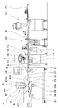
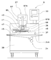
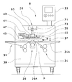
- the molding apparatus 1 includes a top cloth feeding device 3, a shutter molding device 5, a gauge roller device 101, an alignment device 103, and a control device 33 that controls a driving unit of each device. There is.
- the top cloth dough supply device 3 includes a belt conveyor 7 that conveys the bread dough P1, a discharge unit 9 that supplies the top cloth P2 to the upper surface of the bread dough P1, and a feeding device 11 that supplies the top cloth P2 to the discharge unit 9. I have it. Further, on the upstream side of the top dough supply device 3, there is provided a counter roller type gauge roller device 101 for flattening the adjusted bread dough P1 and a discharge portion 9 following the center position of the flat bread dough P1 in the width direction. An aligning device 103 for aligning is provided.
- the belt conveyor 7 includes a photoelectric sensor 13 that detects the conveyance of the bread dough P1.
- the sensor 13 is arranged above the belt conveyor 7 on the upstream side, which is the inlet side of the belt conveyor 7.
- the belt conveyor 7 is provided with an encoder (not shown), and the control device 33 calculates the conveyance position of the bread dough P1 based on the signal from the encoder and the detection signal from the sensor 13 and the length L of the bread dough P1 in the conveyance direction R. Is calculated.
- the discharge part 9 includes a housing 16 having a discharge port 15 formed on the lower surface, and a rotary valve 17 in the housing 16.
- the rotary valve 17 is formed with a communication hole 18 that communicates the flow path on the side of the feeding device 11 and the discharge port 15, and the rotation of the rotary valve 17 opens and closes the discharge port 15.
- the coat fabric feeding device 3 may be, for example, the device described in Japanese Patent No. 4757617 filed by the present applicant, and a detailed description thereof will be omitted.
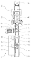
- the shutter forming device 5 is provided with a supply conveyor 23, a shutter device 25, an embossing device 27, a supporting device 29, a carry-out conveyor 31, and a control device 33 for controlling each of these devices on a base 39. That is, in the laminated bread dough forming apparatus 1, the control device 33 that controls the driving unit of each device is provided in the shutter forming device 5, but the control device 33 is provided in another device such as the shutter forming device 5. Alternatively, it may be provided independently.
- the supply conveyor 23 is a belt conveyor for supplying the shutter device 25 with the laminated bread dough P in which the top dough P2 is placed on the upper surface of the bread dough P1.
- the leading end portion 35 of the supply conveyor 23 is provided so as to be capable of reciprocating along the transport direction R between an advanced position (standby position) and a retracted position.
- a photoelectric sensor 37 for detecting the conveyance of the laminated bread dough P is attached to a base 39 on the side of the front end side of the supply conveyor 23.
- the supply conveyor 23 is provided with an encoder (not shown), and the control device 33 calculates the conveyance position of the bread dough P1 based on the signal from the encoder and the detection signal from the sensor 37. Further, the reciprocating movement of the tip portion 35 is controlled by the control device 33 based on the sensing signal from the sensor 37.
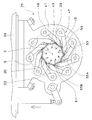
- the shutter device 25 includes a base frame 41 that is attachable to and detachable from the base 39, and nine shutter pieces 45 that are arranged at equal intervals around the center C to surround the center C thereof.
- the shutter 47 is provided.
- a circular through hole 43 is formed in the base frame 41, and the laminated bread dough P formed through the through hole 43 moves downward.
- the plurality of shutter pieces 45 are fixed to nine rotation shafts 49 arranged on the base frame 41 on the circumference S around the center C at equal intervals.
- the rotary shafts 49 are connected to each other by a known power transmission mechanism (not shown) such as a link mechanism or a gear train provided in the base frame 41, and rotate in synchronization with an appropriate drive device. .. By this rotation operation, the shutter pieces 45 are simultaneously swung.
- the shutter piece 45 is provided with a pressing surface 55 facing the center C side of the circumference S.
- the pressing surface 55 is formed as an inclined surface as shown in FIG.
- the pressing surface 55 is formed by a first pressing surface 55A and a second pressing surface 55B that is bent from the first pressing surface 55A and protrudes toward the center C from the upper surface 45U to the lower surface 45L of the shutter piece 45.
- the inclination angles of the first pressing surface 55A and the second pressing surface 55B with respect to the horizontal plane are formed such that the tip end side is smaller than the base end side of the shutter piece 45.
- the pressing surface 55 is a curved surface protruding toward the center C in a plan view.
- the amount of protrusion of the first pressing surface 55A and the second pressing surface 55B toward the center C is formed such that the tip end side of the shutter piece 45 largely protrudes from the base end side.
- At least a portion of the shutter piece 45 that is in contact with the laminated bread dough P is preferably non-adhesive to the laminated bread dough P, and is formed of, for example, a resin material such as high molecular weight polyethylene, polyacetal, or fluororesin.
- the height of the shutter piece 45 is preferably about 1/3 to 2/3 of the height of the laminated bread dough P before forming, but is not limited to this and is suitable for forming the laminated bread dough P. Just do it.
- the shutter 47 opens and closes so as to enlarge or reduce the opening area 61 formed by being surrounded by the pressing surface 55 of each shutter piece 45. Further, when the shutter 47 is opened and closed, the tip end 53 of the shutter piece 45 slides on the pressing surface 55 of the adjacent shutter piece 45 while always being in contact therewith. When the shutter piece 45 swings so that the opening area 61 of the shutter 47 expands or contracts, the opening / closing operation can be temporarily stopped at a position in the middle thereof. The stop position can be adjusted based on a value preset in the control device 33.
- the diameter of the inscribed circle of the opening region 61 at the position of the upper surface 45U of the shutter piece 45 is defined as the opening diameter DI. Further, the diameter of the circumscribed circle of the opening region 61 at the same position is defined as the circumscribed circle diameter DC.
- the center of the opening area 61 coincides with the center C of the circumference S.
- the embossing device 27 is arranged above the shutter device 25.
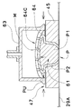
- the embossing device 27 includes a pressing die 63 and a lifting device 65.
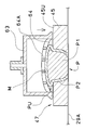
- the pressing die 63 has a cylindrical shape as a whole, and has a cup shape in which a concave portion 64 is formed below.
- the recess 64 is formed by a plurality of blades 64A intersecting each other in a grid pattern.
- the cutting edge of the blade 64A forms a hemispherical concave portion 64 as a whole.
- the upper portion of the blade 64A is a hollow portion 64B (see FIG. 6), and a plurality of exhaust holes 64C formed by the blade 64A communicate with the hollow portion 64B.
- reference numeral 64D (see FIG. 7) is attached to the diameter of the concave portion 64 on the bottom surface of the pressing die 63.
- the pressing die 63 is preferably formed of a material having non-adhesiveness with respect to the overwrap cloth P2, or a metal base material is preferably subjected to non-adhesive surface treatment.
- the elevating device 65 includes a direct-acting actuator 67 that elevates and lowers the pressing die 63 toward and away from the supporting device 29.
- the actuator 67 includes a piston rod 67B that expands and contracts downward from a tubular main body 67A of the actuator 67, and a push die 63 is detachably attached to the lower end of the piston rod 67B.
- the piston rod 67B of the actuator 67 is controlled so that the movable position and the movable speed of expansion and contraction can be adjusted. Further, the piston rod 67B is hollow, and the compressed air A2 is fed into the hollow portion 64B of the pressing die 63 by feeding the compressed air A2 from the compressor or the like into the hollow conduit 67C (see FIG. 6). Is exhausted from the exhaust hole 64C.
- the support device 29 is disposed below the shutter device 25 and supports the bread dough P1 on which the overhanging dough P2 is placed, that is, the laminated bread dough P before forming, and further, the laminated bread dough P that has been formed.
- the supporting device 29 is intermittently driven by an endless conveyor belt 29A that is wound around a plurality of rollers.
- the support device 29 is provided so as to be able to move up and down by interlockingly connecting with a driving means such as a servo motor.
- the conveyor belt 29A moves up and down in the through hole 43 of the base frame 41 of the shutter device 25, and its rising end position is a position in contact with the lower surface 45L of the shutter piece 45.
- the conveyor belt 29A is provided as a support member.
- the carry-out conveyor 31 is a belt conveyor that is continuously provided on the downstream side of the support device 29 that has descended to the descending end position.
- the carry-out conveyor 31 is a device that receives the laminated bread dough P from the support device 29 and further carries it out to the downstream side.
- the surface of the belt conveyor 29 is preferably non-adhesive to the laminated bread dough P, and the belt conveyor 29 is formed of a resin-based material or has a base material coated with a resin material such as polyurethane.
- the bread dough P1 is divided into a required weight from a loaf of bread dough, rounded, and then laid down in a room and adjusted for a required time.
- the bread dough P1 is pressed by the gauge roller device 101, and the bread dough P1 is formed into a substantially circular and flat shape.
- the width W of the bread dough P1 is measured by the aligning device 103 arranged between the gauge roller device 101 and the top dough supplying device 3.
- the bread dough P1 in the width direction of the top dough supply device 3 is aligned with the center position of the discharge port 15 of the top dough supply device 3 in the width direction, the bread dough P1 is overlaid. It is supplied to the belt conveyor 7 of the dough supply device 3.
- the sensor 13 of the belt conveyor 7 detects the conveyance of the bread dough P1.
- the control device 33 calculates the conveyance position and the length L of the bread dough P1 based on the detection signal from the sensor 13.
- the control device 33 causes the feeding device 11 to feed the top dough P2 to the discharging portion 9, and the rotary valve 17 rotates to discharge the dough from the discharge port 15.
- the upper cover dough P2 is discharged, and the thin circular top cover dough P2 is placed so as to substantially cover the conveyed bread dough P1.
- the laminated bread dough P in which the overlaid dough P2 is placed on the bread dough P1 is conveyed by the belt conveyor 7 to the supply conveyor 23 of the shutter forming device 5.
- the leading end portion 35 of the supply conveyor 23 is located at the advanced position that extends downstream so as to cover the shutter 47.
- the control device 33 stops the conveyance of the supply conveyor 23 at a position where the center of the laminated bread dough P coincides with the center C of the opening area 61 of the shutter 47 based on the detection signal for detecting the laminated bread dough P conveyed by the sensor 37. To do.
- the tip end portion 35 moves to the retracted position at once, and the laminated bread dough P placed on the tip end portion 35 falls in the opening area 61 of the shutter 47 enlarged to the set size and rises. It is arranged on the upper surface of the conveyor belt 29A of the stand-by supporting device 29 (arrangement step, see FIG. 6).
- the opening diameter DI of the shutter 47 at this time is referred to as an initial opening diameter.
- the circumscribed circle diameter DC of the opening of the shutter 47 is set smaller than the diameter 64D of the recess 64 of the pressing die 63.
- the opening diameter DI of the shutter 47 is referred to as a first opening diameter (first shutter stop position).
- the laminated bread dough P is pressed from the entire circumferential direction by the pressing surface 55 of the shutter piece 45, and the lower portion PL of the laminated bread dough P is accommodated in the reduced opening area 61 of the shutter 47 and the upper side of the laminated bread dough P.
- the portion PU moves upward from the upper surface of the shutter 47 (synonymous with the upper surface 45U of the shutter piece 45), expands into a substantially hemispherical shape, and is formed into a waist height.
- the shutter 47 adheres the top dough P2 to the side surface of the bread dough P1 and pushes the laminated bread dough P upward to enlarge the upper part into a substantially hemispherical shape to adhere the top dough P2 to the upper surface of the bread dough P1.
- the pressing surface 55 of the shutter piece 45 is formed as an inclined surface. This inclination serves to move the laminated bread dough P upward when the shutter 47 reduces the opening diameter DI and presses the laminated bread dough P from the entire circumferential direction. Further, the second pressing surface 55B formed on the lower side portion of the shutter piece 45 has a function of moving the peripheral edge portion P2E of the top dough P2 on the lower side of the side surface of the laminated bread dough P to the bottom of the bread dough P1 ( Primary pressing step, see FIG. 7).
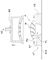
- the actuator 67 of the embossing device 27 is actuated, and the pressing die 63 descends toward the shutter 47 and the supporting member (conveyor belt 29A).
- the lower end position of the pressing die 63 is set at a position slightly apart from the upper surface of the shutter 47 (synonymous with the upper surface 45U of the shutter piece 45), but is controlled so that it can be adjusted appropriately.
- the concave portion 64 accommodates the upper portion PU of the laminated bread dough P that is enlarged in a substantially hemispherical shape, and the pressing die 63 presses the laminated bread dough P1 against the shutter 47 and the conveyor belt 29A (support member).
- the recesses 64 of the pressing die 63 are formed in a lattice shape by the plurality of blades 64A. Therefore, by pressing the upper portion of the laminated bread dough P in which the concave portion 64 is enlarged in a substantially hemispherical shape, a lattice-shaped pattern M is formed by the grooves on the upper portion of the laminated bread dough P. In this embossing step, the whole top dough P2 is brought into close contact with the surface of the bread dough P1 (secondary pressing step, see FIG. 8).
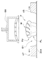
- the shutter 47 is slightly closed to reduce the opening area 61.
- the opening diameter DI is referred to as the second opening diameter (secondary stop position of the shutter).
- the laminated bread dough P in the reduced opening area 61 moves upward, and the upper portion PU of the laminated bread dough P is further expanded into a substantially hemispherical shape.
- the laminated bread dough P expanded in a substantially hemispherical shape is further strongly pressed by the recesses 64 of the pressing die 63, is raised in each exhaust hole 64C of the recesses 64, and the lattice-shaped pattern M is formed more clearly and The effect that the entire dough P2 is brought into close contact with the surface of the bread dough P1 is improved (third pressing step, see FIG. 9).
- the pressing die 63 is lifted by the actuator 67 and stands by at the rising end position until the next laminated bread dough P is arranged.
- the compressed air A2 is discharged from the exhaust hole 64C through the pipe 67C of the piston rod 67B and the hollow portion 64B of the push die 63 for the required time T, and the push die 63 is applied to the top cloth P2.
- the shutter 47 slightly opens and stops.
- the opening diameter DI is set larger than, for example, the first opening diameter in the above-described primary pressing step, and is referred to as the third opening diameter (third stop position of the shutter).
- the pressing surface 55 of the shutter 47 that opens is separated from the laminated bread dough P (step of separating the shutter, see FIG. 10).
- the shutter 47 closes to the set position and stops.
- the opening diameter DI is preferably set to be smaller than the second opening diameter of the above-described second stop position and is referred to as the fourth opening diameter (the fourth stop position of the shutter).
- the shutter 47 that closes reduces the opening area 61 again.
- the pressing surface 55 of the shutter piece 45 again touches the side surface of the laminated bread dough P from the entire circumferential direction, and further presses the dough P2 on the side surface of the bread dough P1.
- the laminated bread dough P moves upward from within the opening region 61, and the upper portion PU of the laminated bread dough P is further expanded into a substantially hemispherical shape.
- the pattern M of the upper portion PU of the laminated bread dough P is expanded, and the thickness of the overcoat dough P2 forming the groove becomes thin.
- the second pressing surface 55B of the shutter piece 45 moves the peripheral edge portion P2E of the top dough P2 to the lower side of the peripheral edge portion P1E of the bottom portion of the bread dough P1 and covers the bread dough P1 with the top dough P2.
- the shutter 47 can bring the entire dough P2 on the bread dough P1 into close contact with the bread dough P1 (fourth pressing step, see FIG. 11).
- the shutter 47 opens to move to the initial position, expands the opening area 61, and releases the laminated bread dough P.
- the lower portion PL of the laminated bread dough P spreads slightly in the radial direction, and the bulge of the upper portion PU of the bread dough P1 enlarged in a substantially hemispherical shape becomes slightly smaller, and the upper portion of the laminated bread dough P becomes larger.
- the pattern M shrinks and the groove becomes slightly deeper (release process, see FIG. 12).
- the supporting device 29 on which the formed laminated bread dough P is placed descends to the descending stop position. Then, the laminated bread dough P is transferred from the supporting device 29 to the carry-out conveyor 31 and further carried out to the next process such as the secondary forming device and the heat treatment device (carry-out process).
- the description of the forming device 1 for the laminated bread dough P according to the first embodiment of the present invention is generally as described above, but the present invention is not limited to this, and various modifications can be made within the scope and scope of the claims. It is possible.
- the steps from the arranging step (see FIG. 5) of arranging the laminated bread dough P in which the overlaid dough P2 is placed on the upper surface of the bread dough P1 (see FIG. 5) to the fourth pressing step (see FIG. 10) are performed.
- the pressing process is performed by the pressing mold 63 (secondary pressing process, see FIG. 8)
- the forming process of the laminated bread dough P can be completed.
- the lower part of the laminated bread dough P supported by the supporting member is surrounded by the shutter 47, and the upper part of the laminated bread dough P is embossed by the pressing die 63.
- the entire circumference of the laminated bread dough P can be surrounded by the respective members, and the whole overlaid dough P2 can be brought into close contact with the bread dough P.
- the shutter 47 is closed to perform the primary pressing step (see FIG. 7) of pressing the laminated bread dough P with the pressing surface 55, but after the placement step, By lowering the pressing die 63 and slightly pressing the laminated bread dough P between the supporting member and the support member, a preliminary pressing step of preliminarily adhering the bread dough P1 and the overlaid dough P2 can be performed.
- a preliminary pressing step of preliminarily adhering the bread dough P1 and the overlaid dough P2 can be performed.
- this pre-pressing when there is a bubble due to a gap between the bread dough P1 and the top dough P2, this bubble can be discharged to the outside.
- the lowering position of the pressing die 63 is set lower than the lowering position during the secondary pressing process.
- the pre-pressing may be performed after placing the top dough P2 on the bread dough P1.
- a forming device similar to the gauge roller device 101 is provided between the top dough supply device 3 and the shutter forming device. It is also possible to do it before the placement step.
- the shutter forming device 6 provided in the forming device 1 for the laminated bread dough P according to the second embodiment of the present invention will be described with reference to FIG.
- the same components as those in the first embodiment are designated by the same reference numerals, and detailed description thereof will be omitted.
- description will be made assuming that the laminated bread dough P having a shell pattern formed on the surface called concha is formed.
- the shutter forming device 6 includes a base 39, a supply conveyor 24, a shutter device 26, an embossing device 27, and a control device 33 that controls each device.
- the supply conveyor 24 is a belt conveyor for supplying the laminated bread dough P in which the top dough P2 is placed on the upper surface of the bread dough P1 below the shutter device 26.
- a sensor 37 for detecting the conveyance of the laminated bread dough P is attached to a base 39 on the upstream side of the supply conveyor 24.
- the supply conveyor 24 is provided with an encoder (not shown), and the control device 33 calculates the transport position of the laminated bread dough P based on the signal from the encoder and the sensing signal from the sensor 37.
- the conveyor belt 24A of the supply conveyor 24 is a support member for the laminated bread dough P.
- the shutter device 26 includes a base frame 41 that is attachable to and detachable from the elevating base 40 of the base 39, and a shutter 47 that is composed of nine shutter pieces 45 that are arranged at equal intervals on the lower surface of the base frame 41.
- the shutter device 26 is arranged above the supply conveyor 24, and the shutter 47 moves away from and approaches the supply conveyor 24 when the elevating base 40 is moved up and down.
- the pressing die 68 of the embossing device 27 can move up and down in the through hole 43 of the base frame 41 of the shutter device 26 and the opening area 61 of the shutter 47, and moves toward and away from the supply conveyor 24.
- the recess 69 of the pressing die 68 is formed so that the plurality of blades 69A expand in a fan shape.
- the cutting edge of the blade 69A forms a hemispherical concave portion 69 as a whole.
- the pressing die 68 has a hollow portion 69B at the upper part of the blade 69A, and a plurality of exhaust holes 69C formed between the plurality of blades 69A communicate with the hollow portion 69B.
- the push die 68 is detachably attached to the lower end of the piston rod 67B of the actuator 67.
- a process of forming the laminated bread dough P by the shutter forming device 6 will be described with reference to FIGS. 13 to 17.
- the laminated bread dough P in which the top dough P2 is placed on the bread dough P1 is conveyed to the supply conveyor 24 of the shutter forming device 6 by the belt conveyor 7 of the top dough supply device 3.
- the supply conveyor 24 stops the conveyance of the laminated bread dough P at a position where the center of the laminated bread dough P coincides with the center C of the opening region 61 of the shutter 47.
- the shutter device 26 descends and stops at the position where the lower surface 45L of the shutter piece 45 contacts the upper surface of the conveyor belt 24A. At this time, the laminated bread dough P is arranged in the opening area 61 of the shutter 47 enlarged to the set size (arrangement step, see FIG. 14).
- the opening diameter DI of the shutter 47 at this time is referred to as an initial opening diameter.
- the shutter piece 45 rotates synchronously toward the center C (the opening area 61 is reduced), and the shutter piece 45 closes and temporarily stops until the opening diameter DI reaches the first opening diameter (of the shutter). Primary stop position).
- the laminated bread dough P is accommodated in the opening area 61 of the shutter 47 in which the lower portion PL of the laminated bread dough P is reduced, and the upper portion PU of the laminated bread dough P moves upward from the upper surface of the shutter 47 and is substantially hemispherical. Expanded to a high waist.
- the second pressing surface 55B of the shutter piece 45 moves the peripheral edge portion P2E of the top dough P2 located below the side surface of the laminated bread dough P to the bottom of the bread dough P1.
- the bread dough P1 is covered with the overwrap dough P2 and is in close contact with each other (first pressing step, see FIG. 15).
- the shutter 47 opens to expand the opening region 61 to the initial position (initial opening diameter) and separate from the laminated bread dough P (separation step).
- the pressing die 68 of the embossing device 27 descends toward the supporting member (conveyor belt 24A) and stops at the set position.
- the pressing die 68 presses the laminated bread dough P against the support member 24A
- the side surface of the laminated bread dough P having a high waist protrudes to the outside.
- the protruding dough P2 covers the peripheral edge portion P1E of the bottom surface of the flattened dough P1.
- a shell-shaped pattern M is formed by grooves on the upper surface of the laminated bread dough P (secondary pressing step, see FIG. 16).
- the press die 68 is supplied with compressed air A2 as it rises, and is separated from the laminated bread dough P without adhering to the overwrap dough P2.
- the shutter 47 closes and stops to a position set to reduce the opening area 61.
- the opening diameter DI is preferably set to be the same as or smaller than the first opening diameter at the primary stop position of the shutter described above.
- the opening diameter DI is referred to as a second opening diameter (secondary stop position of the shutter).
- the pressing surface 55 of the shutter piece 45 again touches the side surface of the laminated bread dough P from the entire circumferential direction, and further presses the dough P2 on the side surface of the bread dough P1.
- the laminated bread dough P moves upward from within the opening region 61, and the upper portion PU of the laminated bread dough P is further expanded into a substantially hemispherical shape (third pressing step, see FIG. 17).
- the shutter 47 opens to expand the opening area 61 to the initial position and release the laminated bread dough P.
- the lower portion PL of the laminated bread dough P spreads slightly in the radial direction, the bulge of the upper portion PU of the bread dough P1 that has expanded to a substantially hemispherical shape becomes slightly smaller, and the groove of the pattern M is slightly deeper. (Release step, see FIG. 18).
- the shutter device 26 rises, and the formed laminated bread dough P is carried out by the supply conveyor 24 to the next process such as the secondary molding device and the heat treatment device (carry-out process). Even when the shutter molding device 6 is used, it is possible to perform the preliminary pressing step after the disposing step, as described above.
- a shutter forming device 6 provided in the forming device 1 for the laminated bread dough P according to the third embodiment of the present invention will be described with reference to FIG.
- the same components as those in the second embodiment are designated by the same reference numerals, and detailed description thereof will be omitted.
- description will be made assuming that a laminated bread dough P, which is called a chocolate chip melon bread and uses a biscuit dough in which chocolate chips are mixed as the top dough P2, is formed.
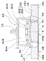
- the pressing die 81 of the embossing device 27 includes a bowl-shaped member 83 having a hollow portion 83A that opens downward, a release sheet 85 made of stretchable and flexible cloth, and a ring made of an elastic material such as rubber. Of the ring 87.
- the release sheet 85 is formed of, for example, a cloth made of nylon, polyurethane, polyester fiber, or the like, a cloth made of silicone rubber, fluororubber, or the like.
- An annular groove 83B is formed on the outer peripheral surface of the bowl-shaped member 83.
- the release sheet 85 covers the hollow portion 83A and the outer peripheral surface, is fixed to the groove 83B by the ring 87, and forms the bottom surface of the pressing die 81.
- the push die 81 is detachably attached to the lower end of the piston rod 67B of the actuator 67.
- FIGS. 19 to 22 A process of forming the laminated bread dough P by the shutter forming device 6 will be described with reference to FIGS. 19 to 22.
- the laminated bread dough P in which the overlaid dough P2 is placed on the upper surface of the bread dough P1 is arranged in the opening region 61 of the shutter 47 which has been enlarged to the initial opening diameter (arrangement step, see FIG. 19).
- the center of the laminated bread dough P is displaced from the center C of the opening region 61 of the shutter 47.
- the shutter piece 45 rotates synchronously toward the center C (the opening region 61 shrinks), the opening diameter DI closes to the position of the first opening diameter, and temporarily stops (the shutter first position). Primary stop position).
- the bread dough P1 not covered with the top dough P2 is pressed by the pressing surface 55 of each shutter piece 45, and the center of the laminated bread dough P is positioned at the center C of the shutter 47 (first Next pressing step, positioning step, see FIG. 20).
- the shutter 47 opens to expand the opening region 61 to the initial position (initial opening diameter), and the shutter piece 45 separates from the laminated bread dough P (separation step).
- the pressing die 81 descends toward the support member (conveyor belt 24A) and stops at the set position.
- the release sheet 85 is extended inside the bowl-shaped member 83 (hollow portion 83A) and deformed into a concave shape.
- the upper dough P2 and the lower dough P1 in the upper part extend in the radial direction and are flattened, and the upper dough P2 covers the upper surface of the dough P1. (Second pressing step, see FIG. 21).
- the pressing die 81 rises, and the release sheet 85 separates from the top cloth P2. At this time, the release sheet 85 is gradually reduced and deformed to prevent the release sheet 85 from adhering to the cover fabric P2.
- the shutter 47 closes and stops at the position where the opening diameter DI becomes the second opening diameter.
- the opening diameter DI is preferably set smaller than the above-described first opening diameter (secondary stop position of the shutter).
- the pressing surface 55 of the shutter piece 45 touches the side surface of the laminated bread dough P from the entire circumferential direction and presses the dough P2 on the side surface of the bread dough P1.
- the laminated bread dough P moves upward from within the opening region 61, and the upper portion PU of the laminated bread dough P is enlarged into a substantially hemispherical shape.
- the second pressing surface 55B of the shutter piece 45 moves the peripheral edge portion P2E of the top dough P2 to the lower side of the peripheral edge portion P1E of the bottom portion of the bread dough P1 and covers the bread dough P1 with the top dough P2.
- the shutter 47 can bring the whole of the overlaid dough P2 into close contact with the bread dough P1 (third pressing step, see FIG. 22).
- the shutter 47 opens to expand the opening region 61 to the initial position and release the laminated bread dough P (release process). Further, the shutter device 26 moves up, and the formed laminated bread dough P is carried out by the supply conveyor 24 (carrying-out step).
- the third pressing step is performed only once, but it is possible to perform a further pressing step by repeating the opening / closing operation of the shutter 47 a plurality of times.
- the opening diameter DI for closing the shutter 47 is set to be the same as the second opening diameter (see FIG. 22), or preferably set to be gradually smaller.
- the compressed air A2 can be supplied to the pressing die 68 when the pressing die 81 moves up.
- the compressed air A2 is discharged from the release sheet 85, and the effect of preventing the sticking to the cover fabric P2 is improved.
- the release sheet is a thin rubber sheet, the compressed air A2 can expand the release sheet downward, and the effect of preventing adhesion to the cover fabric P2 is improved.
- the shutter forming device 8 provided in the forming device 1 for the laminated bread dough P according to the fourth embodiment of the present invention will be described with reference to FIG.
- the same components as those in the first embodiment are designated by the same reference numerals, and detailed description thereof will be omitted.
- the supporting device 29 including a supporting member (conveyor belt 29A) moves up and down from below with respect to the pressing die 63 and the shutter 47 that are fixed at a set position without moving up and down.
- the shutter forming device 8 is provided with a supply conveyor 24, a shutter device 26, an embossing device 28, a supporting device 29, a carry-out conveyor 31, and a control device 33 for controlling each device on a base 39.
- the supply conveyor 24 is a belt conveyor for supplying the laminated bread dough P in which the top dough P2 is placed on the upper surface of the bread dough P1 to the support device 29.
- the shutter device 26 is detachably attached to an elevating base 40 set at a predetermined vertical position with respect to a base 39.
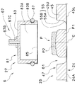
- the pressing die 63 of the embossing device 28 is attached to a bracket 71 fixed to the front surface of the base 39 via a hollow screw member 73 so that its vertical position can be adjusted.
- the pressing die 63 is arranged inside the through hole 43 of the base frame 41 with a predetermined gap from the upper surface 45U of the shutter piece 45. Further, by feeding the compressed air A2 from the compressor or the like to the hollow screw member 73, the compressed air A2 is fed to the hollow portion 64B of the pressing die 63 and exhausted from the exhaust hole 64C.
- the support device 29 is disposed below the shutter device 25, and moves up and down so as to approach and separate from the shutter 47 while supporting the laminated bread dough P before forming which is supplied from the supply conveyor 24.
- the carry-out conveyor 31 is a belt conveyor that is continuously provided on the downstream side of the support device 29 that has descended to the descending end position.
- the carry-out conveyor 31 is a device that receives the laminated bread dough P from the support device 29 and further carries it out to the downstream side.
- the laminated bread dough P in which the overlaid dough P2 is placed on the bread dough P1 is conveyed from the supply conveyor 24 to the support device 29.
- the control device 33 stops the conveyance of the support device 29 at the position where the center of the laminated bread dough P coincides with the center C of the opening region 61 of the shutter 47 based on the detection signal obtained by the sensor 37 detecting the laminated bread dough P.
- the supporting device 29 rises and stops at the position where the upper surface of the conveyor belt 24A contacts the lower surface 45L of the shutter piece 45. At this time, the laminated bread dough P is arranged in the opening area 61 of the shutter 47 enlarged to the set size (arrangement step, see FIG. 24).
- the opening diameter DI of the shutter 47 at this time is referred to as an initial opening diameter.
- the shutter piece 45 rotates synchronously toward the center C (the opening area 61 shrinks), closes to the set position, and temporarily stops (stop position of the shutter).
- the laminated bread dough P is pressed as the opening area 61 of the shutter 47 is reduced (the diameter of the opening is reduced), and the upper portion PU of the laminated bread dough P moves upward from the upper surface of the shutter 47 and expands in a substantially hemispherical shape.
- the laminated bread dough P which expands in a substantially hemispherical shape, enters the recess 64 of the pressing die 63 and eventually contacts the blade 64A.
- a lattice-shaped pattern M is formed on the laminated bread dough P (embossing step). The depth of the groove of the pattern M varies depending on the size of the opening region 61 of the shutter 47, as shown in FIGS. 8 and 9, for example.
- the laminated bread dough P is accommodated in an area surrounded by the pressing die 63, the shutter 47 and the supporting member (conveyor belt 29A), and is pressed from the entire circumference by reducing the opening area 61 of the shutter 47.
- the whole overlaid dough P2 comes into close contact with the bread dough P1 (pressing step).
- the shutter 47 opens to the initial position, and the supporting device 29 on which the formed laminated bread dough P is placed descends to the descending stop position (release process). Then, the laminated bread dough P is transferred from the support device 29 to the carry-out conveyor 31 and carried out (carry-out step).
- the embossing device 28 can be modified so that the pressing die 63 can be lifted and lowered like the embossing device 27 according to the first embodiment. In this case, after the pressing step, as shown in FIG. 10 and FIG. 11, the pressing die 63 is moved up and the shutter 47 is opened and closed to form the laminated bread dough P to a waist height, and the laminated bread dough P is formed above the laminated bread dough P.
- the printed pattern M can be clarified.
- the description of the forming device 1 for the laminated bread dough P according to the embodiment of the present invention is generally as described above, but the present invention is not limited to this, and various modifications can be made within the scope and scope of the claims. ..
- the support member has been described as the conveyor belt 24A of the supply conveyor 24, but the supply conveyor 24 may be replaced with a rotary table device and a rotating table may be used as the support member.
- the concave portion 64 of the pressing die 63 is formed by the plurality of blades 64A
- the surface shape of the concave portion 64 may be a desired pattern to be transferred to the surface of the laminated bread dough P and may be formed from a plurality of uneven surfaces. May be. Further, it may be a hemisphere without a pattern. Further, it is possible to perform the pressing step similar to the molding step according to the second embodiment of the present invention with the shutter molding device 5 according to the first embodiment of the present invention.
- the opening / closing operation of the shutter 47 can be repeated a plurality of times with the pressing die being raised, and the lower portion PL of the laminated bread dough P can be pressed a plurality of times.
- the inclined pressing surface 55 of the shutter piece 45 can move the peripheral edge portion P2E of the top dough P2 to the bottom surface of the bread dough P1.
- the shape of the pressing surface 55 of the shutter piece 45 has been described as the first pressing surface 55A and the second pressing surface 55B being bent, but a plurality of times so as to project from the upper surface 45U toward the lower surface 45L toward the center C side. It is also possible to form a bent shape or an arc shape of a part of a circle or an ellipse.
- the shutter may have three or more shutter pieces and can open and close the opening area. Not only the shutter swings around the rotation axis, but also the shutter pieces slide back and forth to reciprocate. It may be configured to.
- each process in each embodiment may be performed in another embodiment, and a modification in each process is applied to another process. May be done.
Landscapes
- Life Sciences & Earth Sciences (AREA)
- Engineering & Computer Science (AREA)
- Food Science & Technology (AREA)
- Chemical & Material Sciences (AREA)
- Polymers & Plastics (AREA)
- Manufacturing And Processing Devices For Dough (AREA)
- Formation And Processing Of Food Products (AREA)
- Bakery Products And Manufacturing Methods Therefor (AREA)
Abstract
La présente invention aborde le problème classique de fourniture d'un procédé et d'un appareil qui permettent de mouler une pâte à pain en couches et qui permettent de faire adhérer étroitement la totalité de la pâte de garniture à la surface de la pâte à pain. Cet appareil de moulage de pâte à pain en couches comprend : un dispositif d'alimentation en pâte à pain de garniture (3) qui produit une pâte à pain en couches (P) en plaçant une pâte de garniture (P2) sur la pâte à pain (P1); un volet (47) comprenant une pluralité d'éléments (45); un élément de support (29A) disposé au-dessous du volet (47); et un moule de pressage (63), la pâte à pain en couches (p), comprenant la pâte à pain de garniture (P2) placée sur la surface supérieure de la pâte à pain (P1), étant soumise à un compression tandis que toute la périphérie de la pâte à pain en couches (P) est fermée.
Priority Applications (1)
| Application Number | Priority Date | Filing Date | Title |
|---|---|---|---|
| JP2020553910A JP7194195B2 (ja) | 2018-10-31 | 2019-10-29 | 積層パン生地の成形方法および成形装置 |
Applications Claiming Priority (2)
| Application Number | Priority Date | Filing Date | Title |
|---|---|---|---|
| JP2018-205884 | 2018-10-31 | ||
| JP2018205884 | 2018-10-31 |
Publications (1)
| Publication Number | Publication Date |
|---|---|
| WO2020090766A1 true WO2020090766A1 (fr) | 2020-05-07 |
Family
ID=70463186
Family Applications (1)
| Application Number | Title | Priority Date | Filing Date |
|---|---|---|---|
| PCT/JP2019/042246 Ceased WO2020090766A1 (fr) | 2018-10-31 | 2019-10-29 | Procédé et appareil de moulage de pâte à pain en couches |
Country Status (2)
| Country | Link |
|---|---|
| JP (1) | JP7194195B2 (fr) |
| WO (1) | WO2020090766A1 (fr) |
Citations (3)
| Publication number | Priority date | Publication date | Assignee | Title |
|---|---|---|---|---|
| JP2003333979A (ja) * | 2002-05-22 | 2003-11-25 | Kobird Co Ltd | 食品成形方法及びその方法に用いる型打装置 |
| JP2009089622A (ja) * | 2007-10-04 | 2009-04-30 | Rheon Autom Mach Co Ltd | 上面曲面成形装置 |
| JP2012249596A (ja) * | 2011-06-03 | 2012-12-20 | Rheon Automatic Machinerty Co Ltd | 包被食品製造装置及び包被食品製造方法 |
-
2019
- 2019-10-29 WO PCT/JP2019/042246 patent/WO2020090766A1/fr not_active Ceased
- 2019-10-29 JP JP2020553910A patent/JP7194195B2/ja active Active
Patent Citations (3)
| Publication number | Priority date | Publication date | Assignee | Title |
|---|---|---|---|---|
| JP2003333979A (ja) * | 2002-05-22 | 2003-11-25 | Kobird Co Ltd | 食品成形方法及びその方法に用いる型打装置 |
| JP2009089622A (ja) * | 2007-10-04 | 2009-04-30 | Rheon Autom Mach Co Ltd | 上面曲面成形装置 |
| JP2012249596A (ja) * | 2011-06-03 | 2012-12-20 | Rheon Automatic Machinerty Co Ltd | 包被食品製造装置及び包被食品製造方法 |
Also Published As
| Publication number | Publication date |
|---|---|
| JPWO2020090766A1 (ja) | 2021-09-30 |
| JP7194195B2 (ja) | 2022-12-21 |
Similar Documents
| Publication | Publication Date | Title |
|---|---|---|
| CN107249336B (zh) | 包馅食品的成形方法和装置 | |
| JP5750322B2 (ja) | 包被食品の製造方法及び装置 | |
| CN103717097B (zh) | 用于制造包覆食品的开闭装置及其方法 | |
| CN103796518B (zh) | 用于制造包覆食品的开闭装置及其方法 | |
| JPH0722480B2 (ja) | ねり粉ベース材料を自動成形する装置と方法 | |
| JP2005333803A (ja) | 食品用生地整形装置 | |
| WO2020090766A1 (fr) | Procédé et appareil de moulage de pâte à pain en couches | |
| JP6811224B2 (ja) | 包被食品の成形方法及びその方法に用いる切断装置 | |
| JP2003333979A (ja) | 食品成形方法及びその方法に用いる型打装置 | |
| JP7778153B2 (ja) | 包被食品の成形方法 | |
| JP7188710B1 (ja) | 生地成形装置及び方法 | |
| US20030099749A1 (en) | Rising crust manufacturing apparatus | |
| JP2003180321A (ja) | 食品成形方法、及びその装置 | |
| JP2012249596A (ja) | 包被食品製造装置及び包被食品製造方法 | |
| JP3587458B2 (ja) | 食品成形装置 | |
| JP5073219B2 (ja) | 生地の丸め方法および装置 | |
| JP6100073B2 (ja) | 食品成形方法および装置 | |
| HK1238088A1 (en) | Method and device for forming wrapped food item | |
| JP2003088350A (ja) | 食品包み込み成形装置 | |
| HK1238088B (zh) | 包馅食品的成形方法和装置 | |
| HK1119528B (en) | Food manufacturing apparatus | |
| HK1192824B (en) | Shutter device for producing wrapped food product, and method therefor |
Legal Events
| Date | Code | Title | Description |
|---|---|---|---|
| 121 | Ep: the epo has been informed by wipo that ep was designated in this application |
Ref document number: 19877625 Country of ref document: EP Kind code of ref document: A1 |
|
| ENP | Entry into the national phase |
Ref document number: 2020553910 Country of ref document: JP Kind code of ref document: A |
|
| NENP | Non-entry into the national phase |
Ref country code: DE |
|
| 122 | Ep: pct application non-entry in european phase |
Ref document number: 19877625 Country of ref document: EP Kind code of ref document: A1 |