WO2020090837A1 - Antenne, antenne réseau, module de communication radio et équipement de communication radio - Google Patents
Antenne, antenne réseau, module de communication radio et équipement de communication radio Download PDFInfo
- Publication number
- WO2020090837A1 WO2020090837A1 PCT/JP2019/042425 JP2019042425W WO2020090837A1 WO 2020090837 A1 WO2020090837 A1 WO 2020090837A1 JP 2019042425 W JP2019042425 W JP 2019042425W WO 2020090837 A1 WO2020090837 A1 WO 2020090837A1
- Authority
- WO
- WIPO (PCT)
- Prior art keywords
- power supply
- antenna
- conductor
- supply line
- wireless communication
- Prior art date
- Legal status (The legal status is an assumption and is not a legal conclusion. Google has not performed a legal analysis and makes no representation as to the accuracy of the status listed.)
- Ceased
Links
Images



Classifications
-
- H—ELECTRICITY
- H01—ELECTRIC ELEMENTS
- H01Q—ANTENNAS, i.e. RADIO AERIALS
- H01Q1/00—Details of, or arrangements associated with, antennas
- H01Q1/52—Means for reducing coupling between antennas; Means for reducing coupling between an antenna and another structure
- H01Q1/521—Means for reducing coupling between antennas; Means for reducing coupling between an antenna and another structure reducing the coupling between adjacent antennas
- H01Q1/525—Means for reducing coupling between antennas; Means for reducing coupling between an antenna and another structure reducing the coupling between adjacent antennas between emitting and receiving antennas
-
- H—ELECTRICITY
- H01—ELECTRIC ELEMENTS
- H01Q—ANTENNAS, i.e. RADIO AERIALS
- H01Q21/00—Antenna arrays or systems
- H01Q21/06—Arrays of individually energised antenna units similarly polarised and spaced apart
- H01Q21/061—Two dimensional planar arrays
- H01Q21/065—Patch antenna array
-
- H—ELECTRICITY
- H01—ELECTRIC ELEMENTS
- H01Q—ANTENNAS, i.e. RADIO AERIALS
- H01Q21/00—Antenna arrays or systems
- H01Q21/06—Arrays of individually energised antenna units similarly polarised and spaced apart
- H01Q21/08—Arrays of individually energised antenna units similarly polarised and spaced apart the units being spaced along or adjacent to a rectilinear path
-
- H—ELECTRICITY
- H01—ELECTRIC ELEMENTS
- H01Q—ANTENNAS, i.e. RADIO AERIALS
- H01Q21/00—Antenna arrays or systems
- H01Q21/24—Combinations of antenna units polarised in different directions for transmitting or receiving circularly and elliptically polarised waves or waves linearly polarised in any direction
-
- H—ELECTRICITY
- H01—ELECTRIC ELEMENTS
- H01Q—ANTENNAS, i.e. RADIO AERIALS
- H01Q9/00—Electrically-short antennas having dimensions not more than twice the operating wavelength and consisting of conductive active radiating elements
- H01Q9/04—Resonant antennas
- H01Q9/0407—Substantially flat resonant element parallel to ground plane, e.g. patch antenna
- H01Q9/045—Substantially flat resonant element parallel to ground plane, e.g. patch antenna with particular feeding means
-
- H—ELECTRICITY
- H01—ELECTRIC ELEMENTS
- H01Q—ANTENNAS, i.e. RADIO AERIALS
- H01Q9/00—Electrically-short antennas having dimensions not more than twice the operating wavelength and consisting of conductive active radiating elements
- H01Q9/04—Resonant antennas
- H01Q9/0407—Substantially flat resonant element parallel to ground plane, e.g. patch antenna
- H01Q9/0478—Substantially flat resonant element parallel to ground plane, e.g. patch antenna with means for suppressing spurious modes, e.g. cross polarisation
Definitions
- the present disclosure relates to an antenna, an array antenna, a wireless communication module, and a wireless communication device.
- An antenna which is an example of a plurality of embodiments of the present disclosure, includes a radiation conductor, a ground conductor, a first feeding line, a second feeding line, and a connection conductor.
- the first feeder line is configured to be electromagnetically connected to the radiation conductor.
- the first feeder line is configured to excite the radiation conductor in the first direction.
- the second power supply line is configured to be electromagnetically connected to the radiation conductor.
- the second feeder line is configured to excite the radiation conductor in the second direction.
- the connecting conductor is configured to electrically connect the radiating conductor to the ground conductor.
- the connecting conductor is located away from the center of the radiating conductor.
- the connecting conductor is separated from the first feeder line by a first distance.
- the radiation conductor is separated from the second feeder line by a second distance.
- the first distance is substantially equal to the second distance.
- An array antenna which is an example of a plurality of embodiments of the present disclosure, includes a plurality of antenna elements that are the above antennas.
- the plurality of antenna elements are arranged in the first direction.
- a wireless communication module that is an example of a plurality of embodiments of the present disclosure includes the above-described antenna element and a drive circuit.
- the drive circuit is configured to be directly or indirectly connected to each of the first power supply circuit and the second power supply circuit.
- a wireless communication module which is an example of a plurality of embodiments of the present disclosure, includes the above-described array antenna and a drive circuit.
- the drive circuit is configured to be directly or indirectly connected to each of the first power supply circuit and the second power supply circuit.
- a wireless communication device that is an example of a plurality of embodiments of the present disclosure includes the wireless communication module described above and a power supply.
- the power supply is configured to drive the drive circuit.
- FIG. 1 is a perspective view showing an embodiment of an antenna.
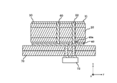
- FIG. 2 is a sectional view showing an embodiment of the antenna.
- FIG. 3 is a block diagram showing an embodiment of the antenna.
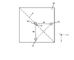
- FIG. 4 is a plan view showing an embodiment of the radiation conductor.
- FIG. 5 is a plan view showing an embodiment of the array antenna.
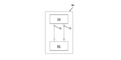
- FIG. 6 is a plan view showing an embodiment of the wireless communication module.
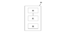
- FIG. 7 is a plan view showing an embodiment of the wireless communication device.
- FIG. 8 is a plan view showing an embodiment of the wireless communication system.
- the antenna size can be increased by placing an external device.
- the present disclosure relates to providing a new antenna, an array antenna, a wireless communication module, and a wireless communication device.
- the antenna 10 includes a base body 20, a radiation conductor 30, a ground conductor 40, a power supply line 50, a connection conductor 60, and a circuit board 70.
- the base 20 is in contact with the radiation conductor 30, the ground conductor 40, the power supply line 50, and the connection conductor 60.
- the radiation conductor 30, the ground conductor 40, the power supply line 50, and the connection conductor 60 are configured to function as the antenna element 11.
- the antenna 10 oscillates at a predetermined resonance frequency and radiates an electromagnetic wave.
- the base body 20 may include either a ceramic material or a resin material as a composition.
- Ceramic materials include aluminum oxide sintered bodies, aluminum nitride sintered bodies, mullite sintered bodies, glass ceramic sintered bodies, crystallized glass obtained by precipitating crystal components in a glass base material, and mica or titanic acid. It includes a microcrystalline sintered body such as aluminum.
- the resin material includes a material obtained by curing an uncured material such as an epoxy resin, a polyester resin, a polyimide resin, a polyamideimide resin, a polyetherimide resin, and a liquid crystal polymer.
- the radiation conductor 30 and the ground conductor 40 may include any of a metal material, an alloy of a metal material, a cured product of a metal paste, and a conductive polymer as a composition.
- the radiating conductor 30 and the ground conductor 40 may all be the same material.
- the radiating conductor 30 and the ground conductor 40 may all be different materials.
- the radiation conductor 30 and the ground conductor 40 may be made of the same material in any combination.
- the metal material includes copper, silver, palladium, gold, platinum, aluminum, chromium, nickel, cadmium lead, selenium, manganese, tin, vanadium, lithium, cobalt, titanium, and the like.
- the alloy includes a plurality of metallic materials.
- the metal paste agent includes a powder of a metal material kneaded together with an organic solvent and a binder.
- the binder includes epoxy resin, polyester resin, polyimide resin, polyamideimide resin, and polyetherimide resin.
- Conductive polymers include polythiophene-based polymers, polyacetylene-based polymers, polyaniline-based polymers, polypyrrole-based polymers, and the like.
- the radiation conductor 30 is configured to function as a resonator.
- the radiation conductor 30 may be configured as a patch type resonator.
- the radiation conductor 30 is located on the base body 20.
- the radiation conductor 30 is located at the end of the base body 20 in the z direction.
- the radiating conductor 30 may be located within the substrate 20.
- a part of the radiation conductor 30 may be located inside the base body 20, and another part may be located outside the base body 20.
- a part of the surface of the radiation conductor 30 may face the outside of the base body 20.
- the radiation conductor 30 extends along the first plane.
- the ends of the radiation conductor 30 are along the first direction and the second direction.
- the first direction and the second direction intersect.
- the first direction may be orthogonal to the second direction.
- the first direction is shown as the x direction.
- the second direction third axis
- the third direction is shown as the z direction.
- the first plane is shown as an xy plane.
- the second plane is shown as the yz plane.
- the third plane is shown as the zx plane.
- planes are planes in the coordinate space and do not indicate a specific surface (plate) or a specific surface (surface).
- the area (surface integral) in the xy plane may be referred to as the first area.
- the area on the yz plane may be referred to as the second area.
- the area in the zx plane may be referred to as the third area.
- Area (surface integral) is counted in units such as square meters.
- the length in the x direction may be simply referred to as “length”.
- the length in the y direction may be simply referred to as “width”.
- the length in the z direction may be simply referred to as “height”.
- the ground conductor 40 may be configured to function as the ground in the antenna element 11. In one example of embodiments, the ground conductor 40 extends along the first plane. The ground conductor 40 faces the radiation conductor 30 in the z direction.
- the power supply line 50 may be configured to supply an electric signal from the outside to the antenna element 11.
- the power supply line 50 can be configured to supply an electric signal from the antenna element 11 to the outside.
- the power supply line 50 may include a first power supply line 51 and a second power supply line 52.
- Each of the first power supply line 51 and the second power supply line 52 is configured to be electrically connected to the radiation conductor 30. However, each of the first power supply line 51 and the second power supply line 52 may be configured to be electromagnetically connected to the radiation conductor 30. In the present disclosure, "electromagnetic connection” includes electrical connection and magnetic connection. Each of the first power supply line 51 and the second power supply line 52 contacts different positions of the radiation conductor 30. As shown in FIG. 2, the ground conductor 40 has a plurality of openings 40a. Each of the first power supply line 51 and the second power supply line 52 passes through the opening 40 a of the ground conductor 40.
- the first power supply line 51 is configured to at least contribute to the supply of an electric signal when the radiation conductor 30 resonates in the x direction.
- the second power supply line 52 is configured to at least contribute to supply of an electric signal when the radiation conductor 30 resonates in the y direction.
- the first feeder line 51 and the second feeder line 52 are configured to excite the radiation conductor 30 in different directions. Since the antenna 10 has the power supply line 50, it is possible to reduce excitation of one of the radiation conductors 30 when exciting one of the radiation conductors 30.
- connection conductor 60 is configured to electrically connect the radiation conductor 30 and the ground conductor 40.
- the connection point between the radiation conductor 30 and the connection conductor 60 serves as a potential reference of the radiation conductor 30 at the time of resonance.
- the connection conductor 60 extends along the z direction.
- connection conductor 60 is located away from the center O of the radiation conductor 30 in the xy plane.
- the connection conductor 60 is connected to a point different from the center O of the radiation conductor 30 in the plan view of the xy plane.
- the change in the current distribution due to the connection of the connection conductor 60 is extremely small.
- the potential reference changes.
- the current distribution changes as the potential reference changes.
- the radiation pattern changes as the current distribution changes.
- the antenna 10 can change the radiation pattern by connecting the connection conductor 60 to a point different from the center O of the radiation conductor 30.
- connection conductor 60 is separated from the first power supply line 51 by a first distance d1.
- first distance d1 the point at which the connection conductor 60 is connected to the radiation conductor 30 is separated from the point at which the first feeder line 51 is connected to the radiation conductor 30 by the first distance d1.
- the connection conductor 60 is separated from the second power supply line 52 by a second distance d2.
- the point at which the connection conductor 60 is connected to the radiation conductor 30 is separated from the point at which the second power supply line 52 is connected to the radiation conductor 30 by the second distance d2.
- the first distance d1 is substantially equal to the second distance d2.
- the connecting conductor 60 can be separated from the first power supply line 51 at a distance of 1 ⁇ 4 of the effective wavelength ⁇ in the x direction.
- the connecting conductor 60 can be separated from the second power supply line 52 by a distance of 1 ⁇ 4 of the effective wavelength ⁇ in the y direction.
- the radiation conductor 30 may include an axis of symmetry S passing through the center O.
- the symmetry axis S passes through the center O and extends in a direction intersecting the x direction and the y direction.
- the symmetry axis S may extend along a direction inclined by 45 degrees from the positive direction of the y-axis to the positive direction of the x-axis when the radiation conductor 30 is a square substantially parallel to the XY plane.
- the first feeder line 51 has symmetry with the second feeder line 52 with the axis of symmetry S interposed therebetween.
- the point where the first power supply line 51 is connected to the radiation conductor 30 and the point where the second power supply line 52 is connected to the radiation conductor 30 may be line-symmetric with respect to the symmetry axis S.
- the connecting conductor 60 is located on the axis of the symmetry axis S. Since the connection conductor 60 is located on the axis of symmetry S, the change in the resonance direction of the radiation conductor 30 can be reduced.
- An effective range of adjustment by the connecting conductor 60 is a range in which a resonant electromagnetic field of half the effective wavelength can be held.
- the direction connecting the first power supply line 51 and the connection conductor 60 is inclined with respect to the x direction.
- the direction connecting the second power supply line 52 and the connection conductor 60 is inclined with respect to the y direction.
- the second power supply line 52 and the connection conductor 60 can excite the radiation conductor 30 also in the x direction.
- the impedance component in each direction acts on the feeder line.
- the antenna 10 can reduce the impedance at the time of input by canceling the impedance components in each direction. By reducing the impedance at the time of input, the antenna 10 can improve isolation in two polarization directions.
- the circuit board 70 includes a first feeding circuit 71 and a second feeding circuit 72.
- the circuit board 70 may include one of the first feeding circuit 71 and the second feeding circuit 72.
- the first feeding circuit 71 is configured to be electrically connected to the first feeding line 51.
- the second power feeding circuit 72 is configured to be electrically connected to the second power feeding line 52.
- the array antenna 12 includes a plurality of antenna elements 11.
- the antenna elements 11 can be arranged along the x direction.
- the antenna elements 11 can be arranged in the x direction.
- the antenna elements 11 can be arranged along the y direction.
- the antenna elements 11 can be arranged in the y direction.
- the array antenna 12 includes at least one circuit board 70.
- the circuit board 70 includes at least one first feeding circuit 71 and at least one second feeding circuit 72.
- the array antenna 12 includes at least one first feeding circuit 71 and at least one second feeding circuit 72.
- the first feeding circuit 71 can be connected to one or more antenna elements 11.
- the first feeding circuit 71 may be configured to supply the same signal to all the antenna elements 11 when feeding the plurality of antenna elements 11.
- the first feeding circuit 71 may be configured to supply the same signal to the first feeding line 51 of each antenna element 11 when feeding the plurality of antenna elements 11.
- the first feeding circuit 71 may be configured to supply signals having different phases to the first feeding line 51 of each antenna element 11 when feeding the plurality of antenna elements 11.
- the second feeding circuit 72 can be connected to one or more antenna elements 11.
- the second feeding circuit 72 may be configured to supply the same signal to all the antenna elements 11 when feeding the plurality of antenna elements 11.
- the second feeding circuit 72 may be configured to supply the same signal to the second feeding line 52 of each antenna element 11 when feeding the plurality of antenna elements 11.
- the second feeding circuit 72 may be configured to supply signals having different phases to the second feeding line 52 of each antenna element 11 when feeding the plurality of antenna elements 11.
- the wireless communication module 80 includes a drive circuit 81.
- the drive circuit 81 is configured to drive the antenna element 11.
- the drive circuit 81 can be configured to supply a transmission signal to at least one of the first power supply circuit 71 and the second power supply circuit 72.
- the drive circuit 81 may be configured to receive power of the reception signal from at least one of the first power supply circuit 71 and the second power supply circuit 72.
- the drive circuit 81 may be configured to be directly or indirectly connected to each of the first power supply line 51 and the second power supply line 52.
- the drive circuit 81 may be configured to supply at least one transmission signal of the first power supply line 51 and the second power supply line 52.
- the drive circuit 81 may be configured to receive power of the reception signal from at least one of the first power supply line 51 and the second power supply line 52.
- the drive circuit 81 may be configured to supply the transmission signal to the first power supply line 51 and receive the reception signal from the second power supply line 52.
- the wireless communication device 90 can include a wireless communication module 80, a sensor 91, and a battery 92.
- the sensor 91 is configured to perform sensing.
- the battery 92 is configured to supply power to any of the wireless communication devices 90.
- the battery 92 may be a power source configured to drive the drive circuit 81 when configured to supply power to the drive circuit 81 of the wireless communication module 80.
- the wireless communication system 95 includes a wireless communication device 90 and a second wireless communication device 96.
- the second wireless communication device 96 is configured to wirelessly communicate with the wireless communication device 90.
- each component can be rearranged so as not to logically contradict each other, and a plurality of components can be combined into one or divided.
- a patch antenna is used as the antenna element 11.
- the antenna adopted as the antenna element 11 is not limited to the patch antenna.
- Other antennas may be adopted as the antenna element 11.
- the array antenna 12 may have a plurality of antenna elements 11 arranged in the same direction.
- two adjacent antenna elements 11 may have different directions. When the orientations of two adjacent antenna elements 11 are different, the antenna elements 11 are excited in the same direction.
- descriptions such as “first”, “second”, and “third” are examples of identifiers for distinguishing the configuration.
- the configurations distinguished by the description such as “first” and “second” in the present disclosure can exchange the numbers in the configurations.
- the first power supply line can exchange the identifiers “first” and “second” with the second power supply line. The exchange of identifiers is done simultaneously. Even after exchanging the identifiers, the configurations are distinguished.
- the identifier may be deleted.
- the configuration in which the identifier is deleted is distinguished by the code.
- the first power supply line 51 can be the power supply line 51.
- the present disclosure includes a configuration in which the circuit board 70 includes the second power supply circuit 72, but does not include the first power supply circuit 71.
Landscapes
- Variable-Direction Aerials And Aerial Arrays (AREA)
- Waveguide Aerials (AREA)
Abstract
La présente invention concerne une nouvelle antenne. Une antenne à titre d'exemple d'une pluralité de modes de réalisation de la présente invention comprend un conducteur de rayonnement, un conducteur de masse, une première ligne d'alimentation, une seconde ligne d'alimentation et un conducteur de connexion. La première ligne d'alimentation est connectée électromagnétiquement au conducteur de rayonnement, et est configurée pour exciter le conducteur de rayonnement dans une première direction. La seconde ligne d'alimentation est connectée électromagnétiquement au conducteur de rayonnement, et est configurée pour exciter le conducteur de rayonnement dans une seconde direction. Le conducteur de connexion est situé à distance du centre du conducteur de rayonnement. Le conducteur de connexion est séparé de la première ligne d'alimentation d'une première distance. Le conducteur de connexion est séparé de la seconde ligne d'alimentation par une seconde distance. La première distance est sensiblement égale à la seconde distance.
Priority Applications (4)
| Application Number | Priority Date | Filing Date | Title |
|---|---|---|---|
| CN201980072988.3A CN113039682A (zh) | 2018-11-02 | 2019-10-29 | 天线、阵列天线、无线通信模块以及无线通信设备 |
| US17/290,774 US11942691B2 (en) | 2018-11-02 | 2019-10-29 | Antenna, array antenna, wireless communication module, and wireless communication device |
| EP19877951.4A EP3876343A4 (fr) | 2018-11-02 | 2019-10-29 | Antenne, antenne réseau, module de communication radio et équipement de communication radio |
| JP2020553949A JP7122389B2 (ja) | 2018-11-02 | 2019-10-29 | アンテナ、アレイアンテナ、無線通信モジュール、および無線通信機器 |
Applications Claiming Priority (2)
| Application Number | Priority Date | Filing Date | Title |
|---|---|---|---|
| JP2018-207478 | 2018-11-02 | ||
| JP2018207478 | 2018-11-02 |
Publications (1)
| Publication Number | Publication Date |
|---|---|
| WO2020090837A1 true WO2020090837A1 (fr) | 2020-05-07 |
Family
ID=70463236
Family Applications (1)
| Application Number | Title | Priority Date | Filing Date |
|---|---|---|---|
| PCT/JP2019/042425 Ceased WO2020090837A1 (fr) | 2018-11-02 | 2019-10-29 | Antenne, antenne réseau, module de communication radio et équipement de communication radio |
Country Status (5)
| Country | Link |
|---|---|
| US (1) | US11942691B2 (fr) |
| EP (1) | EP3876343A4 (fr) |
| JP (1) | JP7122389B2 (fr) |
| CN (1) | CN113039682A (fr) |
| WO (1) | WO2020090837A1 (fr) |
Cited By (1)
| Publication number | Priority date | Publication date | Assignee | Title |
|---|---|---|---|---|
| WO2025204559A1 (fr) * | 2024-03-28 | 2025-10-02 | シャープ株式会社 | Dispositif de traitement du signal |
Families Citing this family (2)
| Publication number | Priority date | Publication date | Assignee | Title |
|---|---|---|---|---|
| JP2769481B2 (ja) | 1992-10-09 | 1998-06-25 | 株式会社大建 | 既存杭引抜き用ケーシング装置 |
| EP3993161A4 (fr) * | 2019-06-25 | 2023-07-26 | Kyocera Corporation | Antenne, module de communication sans fil et dispositif de communication sans fil |
Citations (3)
| Publication number | Priority date | Publication date | Assignee | Title |
|---|---|---|---|---|
| JP2008301364A (ja) * | 2007-06-01 | 2008-12-11 | Sanyo Electric Co Ltd | アンテナ装置、無線装置 |
| JP2016115990A (ja) * | 2014-12-11 | 2016-06-23 | 日本無線株式会社 | 目標識別システム |
| JP2016139965A (ja) | 2015-01-28 | 2016-08-04 | 三菱電機株式会社 | アンテナ装置及びアレーアンテナ装置 |
Family Cites Families (10)
| Publication number | Priority date | Publication date | Assignee | Title |
|---|---|---|---|---|
| JP4031253B2 (ja) * | 2002-01-31 | 2008-01-09 | 三菱電機株式会社 | アンテナ装置 |
| CN1862881B (zh) * | 2005-05-11 | 2011-09-28 | 日立电线株式会社 | 分布相位型圆偏振波天线、高频模块及便携式无线电设备 |
| CN103441339B (zh) * | 2006-04-27 | 2016-01-13 | 泰科电子服务有限责任公司 | 异向材料天线设备 |
| JP2008207762A (ja) * | 2007-02-28 | 2008-09-11 | Matsushita Electric Ind Co Ltd | 車載機 |
| US7825867B2 (en) | 2007-04-26 | 2010-11-02 | Round Rock Research, Llc | Methods and systems of changing antenna polarization |
| US9742077B2 (en) * | 2011-03-15 | 2017-08-22 | Intel Corporation | Mm-wave phased array antenna with beam tilting radiation pattern |
| KR101988382B1 (ko) * | 2013-03-29 | 2019-06-12 | 삼성전자주식회사 | 안테나 장치 및 그를 구비하는 전자 기기 |
| US20170110787A1 (en) * | 2015-10-14 | 2017-04-20 | Apple Inc. | Electronic Devices With Millimeter Wave Antennas And Metal Housings |
| US10594019B2 (en) * | 2016-12-03 | 2020-03-17 | International Business Machines Corporation | Wireless communications package with integrated antenna array |
| CN106935963A (zh) * | 2017-01-20 | 2017-07-07 | 西南电子技术研究所(中国电子科技集团公司第十研究所) | 高隔离度双极化环缝微带天线单元 |
-
2019
- 2019-10-29 CN CN201980072988.3A patent/CN113039682A/zh active Pending
- 2019-10-29 US US17/290,774 patent/US11942691B2/en active Active
- 2019-10-29 EP EP19877951.4A patent/EP3876343A4/fr not_active Withdrawn
- 2019-10-29 WO PCT/JP2019/042425 patent/WO2020090837A1/fr not_active Ceased
- 2019-10-29 JP JP2020553949A patent/JP7122389B2/ja active Active
Patent Citations (3)
| Publication number | Priority date | Publication date | Assignee | Title |
|---|---|---|---|---|
| JP2008301364A (ja) * | 2007-06-01 | 2008-12-11 | Sanyo Electric Co Ltd | アンテナ装置、無線装置 |
| JP2016115990A (ja) * | 2014-12-11 | 2016-06-23 | 日本無線株式会社 | 目標識別システム |
| JP2016139965A (ja) | 2015-01-28 | 2016-08-04 | 三菱電機株式会社 | アンテナ装置及びアレーアンテナ装置 |
Non-Patent Citations (1)
| Title |
|---|
| See also references of EP3876343A4 |
Cited By (1)
| Publication number | Priority date | Publication date | Assignee | Title |
|---|---|---|---|---|
| WO2025204559A1 (fr) * | 2024-03-28 | 2025-10-02 | シャープ株式会社 | Dispositif de traitement du signal |
Also Published As
| Publication number | Publication date |
|---|---|
| CN113039682A (zh) | 2021-06-25 |
| EP3876343A1 (fr) | 2021-09-08 |
| EP3876343A4 (fr) | 2022-07-27 |
| JP7122389B2 (ja) | 2022-08-19 |
| US11942691B2 (en) | 2024-03-26 |
| JPWO2020090837A1 (fr) | 2020-05-07 |
| US20210384644A1 (en) | 2021-12-09 |
Similar Documents
| Publication | Publication Date | Title |
|---|---|---|
| US11831076B2 (en) | Antenna, wireless communication module, and wireless communication device | |
| US11862878B2 (en) | Antenna, array antenna, radio communication module, and radio communication device | |
| US11916294B2 (en) | Antenna, wireless communication module, and wireless communication device | |
| WO2020090838A1 (fr) | Antenne, antenne réseau, module de communication sans fil et dispositif de communication sans fil | |
| JP7122389B2 (ja) | アンテナ、アレイアンテナ、無線通信モジュール、および無線通信機器 | |
| JP7309033B2 (ja) | アンテナ | |
| JP7102593B2 (ja) | アンテナ、無線通信モジュール及び無線通信機器 | |
| US11784402B2 (en) | Antenna, wireless communication module, and wireless communication device | |
| US12160055B2 (en) | Antenna, wireless communication module, and wireless communication device | |
| JP7137012B2 (ja) | アンテナ、無線通信モジュール及び無線通信機器 | |
| JP7242598B2 (ja) | アンテナ、無線通信モジュール及び無線通信機器 | |
| JP2015204497A (ja) | 直線偏波アンテナ、円偏波アンテナおよび電子機器 | |
| JP2020096381A (ja) | アンテナ、無線通信モジュール及び無線通信機器 |
Legal Events
| Date | Code | Title | Description |
|---|---|---|---|
| 121 | Ep: the epo has been informed by wipo that ep was designated in this application |
Ref document number: 19877951 Country of ref document: EP Kind code of ref document: A1 |
|
| NENP | Non-entry into the national phase |
Ref country code: DE |
|
| ENP | Entry into the national phase |
Ref document number: 2020553949 Country of ref document: JP Kind code of ref document: A |
|
| ENP | Entry into the national phase |
Ref document number: 2019877951 Country of ref document: EP Effective date: 20210602 |