WO2020090878A1 - Dispositif de serrage d'ensemble récipient de fluide médical, dispositif d'injection de fluide médical doté d'un dispositif de serrage et système d'injection de fluide médical - Google Patents
Dispositif de serrage d'ensemble récipient de fluide médical, dispositif d'injection de fluide médical doté d'un dispositif de serrage et système d'injection de fluide médical Download PDFInfo
- Publication number
- WO2020090878A1 WO2020090878A1 PCT/JP2019/042547 JP2019042547W WO2020090878A1 WO 2020090878 A1 WO2020090878 A1 WO 2020090878A1 JP 2019042547 W JP2019042547 W JP 2019042547W WO 2020090878 A1 WO2020090878 A1 WO 2020090878A1
- Authority
- WO
- WIPO (PCT)
- Prior art keywords
- holding structure
- syringe
- clamper
- drug solution
- syringe assembly
- Prior art date
- Legal status (The legal status is an assumption and is not a legal conclusion. Google has not performed a legal analysis and makes no representation as to the accuracy of the status listed.)
- Ceased
Links
Images









Classifications
-
- A—HUMAN NECESSITIES
- A61—MEDICAL OR VETERINARY SCIENCE; HYGIENE
- A61M—DEVICES FOR INTRODUCING MEDIA INTO, OR ONTO, THE BODY; DEVICES FOR TRANSDUCING BODY MEDIA OR FOR TAKING MEDIA FROM THE BODY; DEVICES FOR PRODUCING OR ENDING SLEEP OR STUPOR
- A61M5/00—Devices for bringing media into the body in a subcutaneous, intra-vascular or intramuscular way; Accessories therefor, e.g. filling or cleaning devices, arm-rests
- A61M5/14—Infusion devices, e.g. infusing by gravity; Blood infusion; Accessories therefor
- A61M5/142—Pressure infusion, e.g. using pumps
- A61M5/145—Pressure infusion, e.g. using pumps using pressurised reservoirs, e.g. pressurised by means of pistons
Definitions
- the present invention relates to a clamper for holding a drug solution container assembly when injecting a drug solution using a drug solution injector, and various devices having the clamper.
- Medical diagnostic imaging devices include CT (Computed Tomography) scanners, MRI (Magnetic Resonance Imaging) devices, PET (Positron Emission Tomography) devices, angio devices, and MRA (MR Angio) devices.
- CT Computer Tomography
- MRI Magnetic Resonance Imaging
- PET PET
- angio angio
- MRA MR Angio
- the liquid medicine injection device has an injection head to which a liquid medicine container such as a syringe or a liquid medicine bag filled with the liquid medicine is detachably mounted, and an injection control unit for controlling the operation of the liquid injection head.
- the injection head includes a clamper for fixing the drug solution container to the injection head, and a drive mechanism for discharging the drug solution from the drug solution container to the outside with the drug solution container fixed to the injection head.
- the chemical liquid container may be misaligned or removed from the chemical liquid injection device during the injection of the chemical liquid. It is important that the drug solution container be held by the drug solution injector so that the drug solution will not be damaged.
- Patent Document 1 International Publication No. 2011/099551 discloses a drug solution injector having a syringe mounting part on which a syringe assembly is mounted and a clamper holding the syringe assembly mounted on the syringe mounting part. ing.
- the clamper has a base member on which the flange of the syringe assembly is placed, a flange pressing member, and an engaging structure.
- the flange pressing member is rotatably supported by the base member between an open position and a closed position.
- the engagement structure locks the flange pressing member to the base member in the closed position.
- the flange of the syringe assembly is placed on the base member with the flange pressing member in the open position. Next, the flange pressing member is rotated to the closed position, and the flange pressing member is locked to the base member by the engagement structure. This holds the syringe assembly.
- Patent Document 1 International Publication No. 2011/099551
- the syringe assembly is held by closing the clamper after the syringe assembly is mounted on the syringe mounting portion. Therefore, if the syringe assembly is mounted on the syringe mounting portion, the operation of the chemical injection device may be possible even if the user forgets to close the clamper. If the chemical liquid injection operation, which is one of the operations of the chemical liquid injection device, is executed while the clamper is not closed, the syringe assembly may drop during the chemical liquid injection operation.
- This problem can be solved by using a sensor that detects whether the clamper is closed.
- this type of sensor is usually a sensor based on a change in electrical output value, and cannot detect that the clamper is closed when a malfunction such as a failure occurs in the sensor itself.
- One of the objects of the present invention is to provide a clamper and the like that can effectively mount the drug solution container assembly at a predetermined position and close the clamper.
- a clamper detachably holding a drug solution container assembly, comprising: A first holding structure having a first receiving portion for receiving a part of the chemical liquid container assembly in the outer peripheral direction; A second holding structure that has a second receiving portion that receives a part of the chemical liquid container assembly in the outer peripheral direction, and that holds the chemical liquid container assembly in cooperation with the first holding structure; Have The second holding structure is movable between an open position and a closed position with respect to the first holding structure, and the second receiving portion receives a part of the drug solution container assembly in the open position.
- a clamper is provided that is supported so that
- a clamper of the present invention A drive mechanism for discharging the drug solution contained in the drug solution container assembly held by the clamper from the drug solution container assembly,
- a liquid medicine injection device having:
- a liquid injector according to the present invention, A drug solution container assembly for containing a drug solution; A system is provided having.
- the “axial direction” of the drug solution container assembly or the syringe assembly refers to the longitudinal direction of the drug solution container assembly or the syringe assembly.
- a typical drug solution container assembly or syringe assembly has an opening for discharging a drug solution at one axial end thereof.
- the “radial direction” of the drug solution container assembly or the syringe assembly refers to a direction perpendicular to the “axial direction”.
- the present invention it is possible to mount the drug solution container assembly at a predetermined position by utilizing the movement of the drug solution container assembly associated with the closing operation of the clamper.
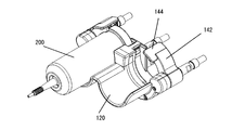
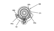
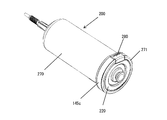
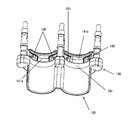
- FIG. 1 is a schematic block diagram of a medical image capturing system according to an embodiment of the present invention. It is a perspective view which shows an example of the external appearance of the injection head which can be equipped with the chemical injection device shown in FIG. It is a perspective view of the syringe mounting part of the injection head shown in FIG. It is a figure explaining one form of arrangement of the 1st holding structure and the 2nd holding structure. It is a figure explaining the other form of arrangement
- FIG. 7B is a view showing the state where the syringe assembly is received in the second holding structure in FIG. 7A.
- FIG. 7B is a view showing the state where the syringe assembly is received by the second holding structure in the open position in the injection head shown in FIG. 7A.
- FIG. 7B is a view showing one form of a syringe release mechanism applicable to a clamper of the present invention.
- FIG. 7A is a principal part perspective view of a clamper which shows the example of arrangement
- FIG. 1 there is shown a block diagram of a medical image capturing system according to an embodiment of the present invention, which includes a liquid medicine injection device 100 and a medical image capturing device 500. Further, the liquid medicine injection device 100 and the medical image capturing device 500 can be connected to each other so that data can be transmitted and received between them.
- the connection between the two may be a wired connection or a wireless connection.
- the medical image capturing apparatus 500 includes an image capturing operation unit 520 that executes an image capturing operation, and an image capturing control unit 510 that controls the operation of the image capturing operation unit 520, and a subject to which the liquid medicine is injected by the liquid medicine injector 100. Medical images including tomographic images and / or three-dimensional images can be acquired.
- the imaging operation unit 520 generally includes a bed for a subject, an electromagnetic wave irradiation unit that irradiates a predetermined space on the bed with electromagnetic waves, and the like.
- the image capturing control unit 510 controls the operation of the entire medical image capturing apparatus, such as determining the image capturing condition and controlling the operation of the image capturing operation unit 520 according to the determined image capturing condition.
- the imaging control unit 510 can be configured by including a so-called microcomputer, and can have a CPU, a ROM, a RAM, and an interface with other devices.
- a computer program for controlling the medical image capturing apparatus 500 is installed in the ROM.
- the CPU controls the operation of each unit of the medical image capturing apparatus 500 by executing various functions corresponding to this computer program.
- the medical image capturing apparatus 500 may further include a display unit 504 such as a liquid crystal display capable of displaying an image capturing condition and an acquired medical image, and an input unit 503 such as a keyboard and / or a mouse for receiving an input of the image capturing condition. it can. At least part of the data used to determine the imaging condition is input from the input unit 503 and transmitted to the imaging control unit 510. The data displayed on the display unit 504 is transmitted from the imaging control unit 510.
- a touch panel in which a touch screen is arranged as an input unit on the display of the display unit can also be used as the input unit 503 and the display unit 504.
- a part of the input unit 503, the display unit 504, and the imaging control unit 510 can be incorporated into one housing as a console for the medical image imaging apparatus.
- the drug solution injector 100 is a device used to inject a drug solution filled in a syringe assembly 200, which is a drug solution container assembly, into a blood vessel of a subject through an injection circuit 300, and at least one piston drive mechanism 130. And at least one input unit 103, at least one display unit 104, and an injection control unit 101.
- the piston drive mechanism 130 is a mechanism that operates a piston of a syringe, and in the present embodiment, the drug solution injector 100 is configured so that two kinds of drug solutions (for example, a contrast agent and a physiological saline solution) can be separately or simultaneously injected.
- one syringe assembly 200 can be mounted, and has two piston drive mechanisms 130 for independently operating the respective pistons of these two syringe assemblies 200.
- the number of piston drive mechanisms 130 may be one, or may be three or more, depending on the number of syringe assemblies 200 mounted on the chemical liquid injector 100.
- the injection control unit 101 uses at least a part of the data input from the input unit 103 to determine the injection conditions such as the injection amount and the injection speed of the drug solution, and to inject the drug solution from the syringe according to the determined injection conditions.
- the operation of the liquid injector is controlled by controlling the operation of the piston drive mechanism 130 and the display of the display unit 104.
- the injection control unit 101 can be configured to include a so-called microcomputer, and can have a CPU, a ROM, a RAM, and an interface with other devices.
- a computer program for controlling the chemical liquid injector 100 is installed in the ROM.
- the CPU can control the operation of each unit of the chemical injection device 100 by executing various functions in accordance with this computer program.
- the input unit 103 is a unit that accepts inputs such as data used by the injection control unit 101 to determine the injection conditions of the drug solution.
- the input unit 103 may be a known input device such as a keyboard and / or a mouse.
- the data input from the input unit 103 is transmitted to the injection control unit 101, and the data displayed on the display unit 104 is transmitted from the injection control unit 101.
- the display unit 104 is controlled by the injection control unit 101, and displays data necessary for determining the injection conditions of the drug solution, the injection protocol, the injection operation, and various warnings.
- the injection protocol indicates what kind of liquid medicine is injected, how much it is, and at what speed.
- the injection rate may be constant or may change with time.
- the injection protocol also includes information on the order in which the drug solutions are injected.
- any known injection protocol can be used.
- a known procedure can be used as the procedure for creating the injection protocol.
- the injection protocol may also include the maximum allowable injection pressure (pressure limit). When the pressure limit is set, the injection pressure is monitored during the injection operation, and the operation of the piston drive mechanism 130 is controlled so that the injection pressure does not exceed the set pressure limit.
- the display unit 104 may be a known display device such as a liquid crystal display device.
- a touch panel in which a touch screen is arranged as an input unit on the display of the display unit can also be used as the input unit 103 and the display unit 104.
- the chemical injection device 100 can have an injection head 100a and a console 100b as a housing.
- the injection head 100a can have a piston drive mechanism 130, and the syringe assembly 200 is removably mounted.
- the console 100b can have an injection control unit 101, an input unit 103, and a display unit 104.
- the input unit 103 and / or the display unit 104 different from the input unit 103 and the display unit 104 included in the injection control unit 101 may be provided in the injection head 100a, or the injection head 100a and the console 100b. It may be provided separately.
- the injection head 100a is configured so that two syringe assemblies 200 can be detachably mounted in parallel with each other as a drug solution container assembly (in FIG. 2, one syringe is shown for simplification). Only assembly 200 is shown).
- the syringe assembly 200 has a syringe 220 and a protective cover 270 into which the syringe 220 is inserted.
- the syringe 220 is a syringe 220 generally called a rodless syringe, and has a cylinder 221 and a piston 222 inserted into the cylinder 221 so as to be movable back and forth.
- a cylinder flange 221a and a nozzle portion 221b are formed at the end and the tip of the cylinder 221, respectively.
- a convex portion (not shown) held by the piston drive mechanism 130 is integrally formed at the end of the piston 222.
- the syringe 220 may be a prefilled type syringe provided with a drug solution in a state filled with a drug solution, or a field-filled type syringe filled with a drug solution at a medical site.
- the drug solution filled in the syringe 220 is pushed out of the syringe 220 via the nozzle portion 221b.
- An extension tube (not shown) having an injection needle or catheter connected to its tip is connected to the nozzle portion 221b, and the injection needle or catheter is punctured or inserted into the blood vessel of the subject to inject the drug solution in the syringe 220 into the subject.
- the liquid medicine filled in the syringe 220 include a contrast agent and physiological saline.
- the syringe 220 may be filled with a therapeutic drug solution such as an anti-cancer agent instead of the contrast agent and may be administered to the subject.
- a drug solution injected using the drug solution injector 100 often has a high viscosity like a contrast agent. Further, in particular, when a blood vessel image of a subject is taken using the angio apparatus, a contrast agent is injected through a thin catheter. As a result, the internal pressure of the cylinder 221 tends to be extremely high during the injection of the contrast agent. This high internal pressure causes the cylinder 221 to expand, which may cause various problems in the injection of the chemical liquid.
- the protective cover 270 has a cylindrical shape so that the cylinder 221 is inserted without a gap between the outer peripheral surface of the cylinder 221 and the inner peripheral surface of the protective cover 270 in order to suppress expansion due to an increase in internal pressure of the cylinder 221 during injection of the chemical liquid. It is a component that is configured in a shape. Since the protective cover 270 plays this role, the protective cover 270 is formed with a wall thickness having a mechanical strength sufficient to withstand the internal pressure acting on the cylinder 221 during the injection of the chemical liquid.
- An opening is formed at the tip of the protective cover 270, and the cylinder 221 is inserted into the protective cover 270 with the nozzle portion 221b protruding from this opening.
- a cover flange 271 having a ring-shaped recess for receiving the cylinder flange 221a of the cylinder 221 is formed.
- the injection head 100a has two piston drive mechanisms 130 (see FIG. 1) that are driven independently of each other for advancing and retracting the pistons 222 of the two syringe assemblies 200 attached, and each syringe assembly 200 is attached. It is arranged corresponding to the position.
- Each of the piston drive mechanisms 130 holds a presser 131 that holds the above-mentioned convex portion at the end of the piston 222, a drive source (not shown) such as a motor that advances and retracts the presser 131, and a power transmission mechanism that connects these. (Not shown).
- the syringe assembly 200 mounted on the injection head 100a can inject the drug solution filled in the syringe 220 into the subject by moving the piston 222 forward by the piston drive mechanism 130.
- the liquid medicines filled in the two syringes 200 are separately, sequentially or simultaneously controlled by appropriately controlling the operation of each piston drive mechanism 130. Can be injected into.
- the piston drive mechanism 130 a known mechanism generally used in this type of injection device can be adopted.
- the operation of each piston drive mechanism 130 is controlled by the injection control unit 101 according to the injection protocol when injecting the drug solution, but it is preferable that the piston drive mechanism 130 can be operated in any other manner.
- the input unit 103 may further include a button group 103a and / or a manual knob 103b in the injection head 100a, which includes a button for arbitrarily advancing the presser 131 and a button for arbitrarily retracting the presser 131.
- the injection control unit 101 controls the operation of each piston drive mechanism according to the pressing operation of each button of the button group 103a and the rotation operation of the manual knob 103b by the operator.
- the tip of the injection head 100a is provided with a syringe assembly receiver 120 and a clamper 140 that constitute a syringe mounting portion on which the syringe assembly 200 is mounted.
- the syringe assembly receiver 120 is located closer to the tip side than the clamper 140, and has two recesses 121 that can individually receive the outer peripheral surface of the protective cover 270.
- the syringe assembly 200 is injected by holding the cover flange 271 by the clamper 140 in a state where the syringe assembly receiver 120 is received by the syringe assembly receiver 120 with the nozzle portion 221b facing the front end side and is placed on the syringe placing portion. It is fixed to the head 100a.
- clamper 140 will be described in more detail with reference to FIG.
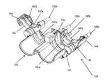
- the clamper 140 has a first holding structure 141 that cooperates to hold the syringe assembly 200 and at least one second holding structure 142.
- the first holding structure 141 and the second holding structure are configured to hold the syringe assembly 200 in a state where the syringe assembly 200 is placed on the syringe mounting portion.
- the clamper 140 has two second holding structures 142 so that the injection head 100a (see FIG. 2) can mount the two syringe assemblies 200.
- the number of the second holding structures 142 may be one, or may be three or more, corresponding to the number of the syringe assemblies 200 mounted on the injection head 100a.
- the configuration of the first holding structure 142 and the configuration of the syringe assembly receiver 120 are changed according to the number of syringe assemblies 200 that can be mounted. For example, if the number of syringe assemblies 200 that can be mounted is one, the first holding structure 141 has one flange receiving portion 141a (described later), and the syringe assembly receiver 120 has one recess 121.
- the clamper 140 may further include at least one support member that supports the first holding structure 141 and the second holding structure 142 with respect to the injection head 100a.
- the clamper 140 has, as a support member, a center shaft 150a and two clamper shafts 150b arranged in parallel with the center shaft 150a on both sides of the center shaft 150a.
- the first holding structure 141 is fixedly supported by the center shaft 150a and the two clamper shafts 150b with respect to the injection head 100a.
- the two second holding structures 142 are rotatably supported around the clamper shaft 150b by the left and right clamper shafts 150b.
- the first holding structure 141 has two flange receiving portions 141a (first receiving portions) located between the center shaft 150a and the clamper shaft 150b as a structure for receiving a part of the syringe assembly 200 in the outer peripheral direction.
- each flange receiving portion 141a can receive a part of the cover flange 271 along the outer peripheral direction so as to be substantially immovable in the axial direction of the syringe assembly 200 but movably in the radial direction. It is configured as a recess that can be formed.
- the first holding structure 141 can be configured by one member, or can be configured by combining a plurality of members.
- the second holding structure 142 is movably supported between an open position and a closed position with respect to the first holding structure 141, can receive a part of the flange assembly 200 in the outer peripheral direction in the open position, and In the closed position, it is configured to cooperate with the first retaining structure 141 to retain the syringe assembly 200.
- the second holding structure 142 also has a flange receiving portion 142a (second receiving portion) as a structure for receiving a part of the syringe assembly 200 in the circumferential direction similarly to the first holding structure 141. have.
- the flange receiving portion 142a can receive a part of the cover flange 271 along the outer peripheral direction so as to be substantially immovable in the axial direction of the syringe assembly 200 but movably in the radial direction. It is configured as a recess.
- the flange receiving portion 142a is preferably provided with a non-slip member 142b for preventing the syringe assembly 200 from rotating. Any material may be used to form the anti-slip member 142b, and for example, a rubber material such as silicone rubber may be used. By forming the anti-slip member 142b from a rubber material, the anti-slip member 142b can also serve as a cushion.
- the second holding structure 142 can be formed of one member or a combination of a plurality of members.
- the flange receiving portion 141a of the first holding structure 141 and the flange receiving portion 142a of the second flange holding structure 142 are such that when the second holding structure 142 is in the closed position, both flange receiving portions 141a, 142a cooperate. Configured to operatively and immovably receive the cover flange 271 both axially and radially of the syringe assembly 200. This holds the syringe assembly 200.
- immovable as used in this specification includes not only that the target structure does not move at all, but also that the structure can move within a clearance that occurs due to design dimensional tolerances and the like.
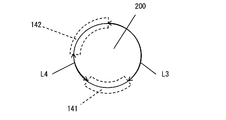
- the total length of the length L1 and the length L2 is more than half the length of the entire circumference of the syringe assembly 200 in the circumferential direction.
- the length L1 is the circumferential length of the portion of the syringe assembly 200 that is received by the flange receiving portion of the first holding structure 141.
- the length L2 is the circumferential length of the portion of the syringe assembly 200 that is received by the flange receiving portion of the second holding structure 142.
- each of length L3 and length L4 may be less than half the length of the entire circumference of syringe assembly 200 in the circumferential direction.
- the lengths L3 and L4 are circumferential lengths of the portion of the syringe assembly 200 that is not received by either the flange receiving portion of the first holding structure 141 or the flange receiving portion of the second holding structure 142.
- the former configuration is adopted.
- the first holding structure 141 and the second holding structure 142 may be continuously arranged in the circumferential direction of the syringe assembly 200, or may be arranged separately.
- the shapes of the first holding structure 141 and the second holding structure are not particularly limited and may be arbitrary. However, at least each inner surface (the surface facing the syringe assembly when the syringe assembly is held) has a length along the outer peripheral direction of the syringe assembly 200 so that a part of the outer peripheral direction of the syringe assembly 200 can be received. It is preferable that the shape has In this embodiment, since the syringe assembly 200 has a cylindrical outer shape as a whole, the flange receiving portion 141a of the first holding structure 141 and the flange receiving portion 142a of the second holding structure 142 are substantially semi-circular. Is formed in.
- the movement path of the second holding structure 142 may be arbitrary as long as it can move between the open position and the closed position.
- the movement of the second holding structure 142 between the open position and the closed position may be rotation as in the present embodiment, linear movement, or a combination thereof. Good.
- the second holding structure 142 is movably supported between the open position and the closed position, any part of the second holding structure 142 may be supported, and one end thereof is supported. Alternatively, other parts may be supported.
- the second holding structure 142 is configured in a semi-circular shape as a whole corresponding to the outer shape of the syringe assembly 200, and the intermediate portion in the longitudinal direction of the semi-circular shape is attached to the clamper shaft 150b and the clamper shaft 150b.
- the second holding structure 142 is rotatably supported around which the part of the flange receiving part 141a is located in the flange receiving part 141a of the first holding structure 141 when in the closed position. Then, with the movement of the second holding structure 142 toward the open position, a part of the flange receiving portion 142a located in the flange receiving portion 141a is configured to be detached from the flange receiving portion 141a.
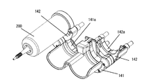
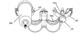
- the user When mounting the syringe assembly 200 on the injection head 100a, the user first moves the second holding structure 142 to the open position. In this state, the user places the syringe assembly 200 on the second holding structure 142 so that the cover flange 271 of the syringe assembly 200 is received by the flange receiving portion 142a of the second holding structure 142 (see FIGS. 5A and 5B). ).
- the flange receiving portions 141a, 142a of the first holding structure 141 and the second holding structure 142 are both formed in a semi-circular shape, and the second holding structure 142 has a long length. It is supported at the middle part of the direction (direction along the arc).
- the orientation of the open end of the flange receiving portion 142a of the second holding structure 142 is the same as the orientation of the open end of the flange receiving portion 141a of the first holding structure 141.
- the second holding structure 142 has a posture in which it is easy to receive the syringe assembly 200.
- the syringe is provided at any position that creates a space in which the syringe assembly 200 can be radially inserted between the first holding structure 141 and the second holding structure 142.
- the assembly 200 can be received.
- the open position can be any position that creates a space between the first retaining structure 141 and the second retaining structure 142 that allows the syringe assembly 200 to be radially inserted.
- the user moves the second holding structure 142, in which the syringe assembly 200 is received, to the closed position (FIGS. 6A and 6B).
- the syringe assembly 200 moves (rotates) with the second holding structure 142 and is received by the syringe assembly receiver 120, whereby the syringe assembly 200 is The syringe is mounted at a fixed position placed on the syringe mount.
- the cover flange 271 of the syringe assembly 200 is held by the first holding structure 141 and the second holding structure 142.
- an injection needle or a catheter is connected to the syringe assembly 200 via an extension tube to set the injection conditions of the drug solution and set the drug solution injector 100.
- the drug solution can be injected into the subject through a procedure similar to the conventional one such as operating.
- the syringe assembly 200 mounted on the injection head 100a can be removed from the injection head 100a in the reverse order of the mounting procedure described above.
- the syringe assembly 200 is placed on the second holding structure 142 when the second holding structure 142 is in the open position, and in that state the second holding structure 142 is moved to the closed position.
- This mounts the syringe assembly 200 in place. This allows the syringe assembly 200 to be mounted at a fixed position and held by the clamper 140 at the same time by an extremely intuitive operation of moving the second holding structure 142 on which the syringe assembly 200 is placed from the open position to the closed position. be able to.
- the clamper 140 can have a stop in the open position and / or a stop in the closed position of the second retaining structure 142.
- the clamper 140 having the stopper in the open position can stabilize the position of the second holding structure 142 in the open position and facilitate the reception of the syringe assembly 200 in the second holding structure 142. Since the clamper 140 has the stopper mechanism at the closed position, the second holding structure 142 can maintain the closed state of the clamper 140 at the closed position.
- any mechanism that can hold the second holding structure 142 in the open position and / or the closed position in a disengageable manner can be used.
- the stopper is a combination of a spring plunger attached to the second holding structure 142 and an engagement recess formed in a member that contacts the second holding structure 142 in the open position and / or the closed position. it can.
- the relationship between the spring plunger and the engagement recess may be reversed.
- the spring plunger has a main body, a movable body such as a ball or a pin held in the main body so as to be movable back and forth with respect to the main body, and a spring for urging the movable body from the inside of the main body.
- the spring plunger has a structure in which a part of the movable body projects from the main body by the biasing force of the spring when no load is applied, but the movable body sinks into the main body when a load is applied.
- the engagement recess is formed at a position facing the spring plunger when the second holding structure 142 is in the open position and / or the closed position.
- the clamper 140 may have a syringe lock structure that detachably locks the syringe assembly 200 received by the first holding structure 141.
- the syringe lock mechanism include a holding hook 143 (see FIG. 3 and the like) provided on the first holding structure 141.
- the holding hook 143 is provided in the flange receiving portion 141a of the first holding structure 141 at a position that engages with the outer peripheral surface of the cover flange 271 of the syringe assembly 200 received by the flange receiving portion 141a.
- the clamper 140 can also include both a syringe lock mechanism and a lock mechanism in the closed position of the second holding structure 142, which allows the syringe assembly 200 to be held more firmly.
- the second holding structure 142 can have an operating lever 144 for the user to move the second holding structure 142 between an open position and a closed position.
- the position of the operation lever 144 on the second holding structure 142 may be arbitrary, but by providing the operation lever 144 at the end portion away from the rotation center of the second holding structure 142, a smaller force is applied.
- the second holding structure 142 can be moved (rotated).
- the operation lever 144 of the second holding structure 142 which is the farthest from the syringe mounting portion (syringe assembly receiver 120) when the second holding structure 142 is in the closed position, is viewed from the axial direction of the syringe assembly 200. It is preferably located in a portion (see, eg, FIG. 6B).
- the clamper 140 may be configured such that the syringe assembly 200 received in the second holding structure 142 is adsorbed to the second holding structure 142.
- Magnetism can be used to attract the syringe assembly 200.
- FIG. 7A An example of an adsorption structure using magnetism is shown in FIG. 7A.
- the second holding structure 142 and the syringe assembly 200 have magnetic attraction members 145a and 145b, respectively.
- these magnetic attraction members 145a and 145b face each other when the syringe assembly 200 is received by the second holding structure 142, and one magnetic attraction member 145a and the other magnetic attraction member 145b. Are arranged in a pair.
- the magnetic attraction member 145b on the syringe assembly 200 side is arranged near or inside the outer peripheral surface of the cover flange 271, and the magnetic attraction member 145a on the second holding structure 142 side is arranged in the flange receiving portion 142a. There is.
- the syringe assembly 200 received in the second holding structure 142 is magnetically attracted by the magnetic attraction members 145a and 145b, so that the posture of the injection head 100a is, for example, the tip side of the injection head 100a (the syringe assembly receiving 120 side).
- the syringe assembly 200 can be reliably received by the second holding structure 142 without being dropped from the second holding structure 142. be able to.
- the second holding structure 142 that has received the syringe assembly 200 is rotated from the open position to the closed position, it is possible to prevent the syringe assembly 200 from falling off the second holding structure 142.
- the second holding structure 142 is rotated from the closed position to the open position, the syringe assembly 200 is also rotated to the open position, so that the syringe assembly 200 can be easily removed.
- the pair of magnetic attraction members 145a and 145b As a combination of the pair of magnetic attraction members 145a and 145b, a combination of magnets and a combination of a ferromagnetic material such as iron and a magnet can be mentioned. By using magnets for both of the pair of magnetic attraction members 145a, 145b, stronger attraction force can be obtained.
- the number of pairs of the magnetic attraction members 145a and 145b may be one or may be plural.
- By having a plurality of pairs of magnetic attraction members 145a and 145b not only the syringe assembly 200 can be attracted more strongly, but also the syringe assembly 200 can be attracted to the second holding structure 142 in a specific direction in the circumferential direction. .. This is effective when the circumferential direction of the syringe assembly 200 held by the clamper 140 is fixed.
- the magnetic attraction member 145a provided in the second holding structure 142 is a magnet
- a magnetic attraction band 145c extending in the circumferential direction of the syringe assembly 200 is used. Can be used.
- the magnetic attraction band 145c is fixed to the outer peripheral surface of the cover flange 271 of the protective cover 270. Accordingly, when the syringe assembly 200 is held by the second holding structure 142, the restriction on the circumferential direction of the syringe assembly 200 can be relaxed.
- a flexible sheet-shaped ferromagnetic material and a ferromagnetic material processed into a curved shape along the outer peripheral surface of the cover flange 271 can be used.
- a rubber magnet that can be curved along the outer peripheral surface of the cover flange 271 and a magnet formed into a curved shape along the outer peripheral surface of the cover flange 271 can also be used.
- the length of the magnetic adsorption zone 145c in the circumferential direction of the syringe assembly 200 may be arbitrary, but it is preferable that it is as long as possible in order to exert the above effect more effectively.
- the magnetic attraction band 145c has a length extending over substantially the entire outer peripheral surface of the cover flange 271 excluding a portion where the release button 280 provided on the cover 271 of the protective cover 270 is present. is doing.
- the syringe assembly 200 shown in FIG. 7C has a release button 280, but the release button 280 is not an essential component. Therefore, when the syringe assembly 200 does not have the release button 280, it is possible to use the magnetic attraction band 145c having the length over the entire outer peripheral surface of the cover flange 271.
- the release button 280 is a mechanism for holding and releasing the syringe 220 on the protective cover 270.
- the release button 280 is rotatably supported on the cover flange 271 by a shaft parallel to the diameter direction of the cover flange 271.
- the release button 280 is rotatable between a first position where it engages with the rear end surface of the cylinder of the syringe 220 and a second position where the engagement is released. Further, the release button 280 is elastically supported so as to rotate from the first position to the second position by being operated.
- the syringe assembly 200 has the release button 280, it is necessary to operate the release button 280 in order to remove the syringe 220 from the protective cover 270, so that the syringe 220 accidentally drops from the protective cover 270. Can be prevented.
- the second holding structure 142 is supported at the longitudinal middle portion along the outer circumferential direction of the syringe assembly 200, and when the second holding structure 142 is in the closed position, the clamper 140 is configured to move.
- the syringe assembly 200 is configured to be held in a state where a part of the assembly 200 in the circumferential direction is opened.
- the clamper 140 may be configured to hold the syringe assembly 200 all around.
- FIG. 8A An example of such a clamper 140 is shown in FIG. 8A.
- the clamper 140 shown in FIG. 8A can be configured in the same manner as the clamper 140 shown in FIG. 3 and the like, except that one end of the second holding structure 142 is supported by a clamper shaft (not shown). ..
- the second holding structure 142 is supported at one end thereof, so that when the second holding structure 142 is in the open position, the second holding structure 142 is largely opened with respect to the first holding structure 141.
- the second holding structure 142 can receive the syringe assembly 200 at a position relatively distant from various structures such as the presser 131 of the injection head 100a, as shown in FIG. 8B.
- the injection head 100a and / or the syringe assembly 200 may be damaged by accidentally hitting the syringe assembly 200 with the main structure of the injection head 100a when the syringe assembly 200 is attached to the injection head 100a. Can be lowered.
- the clamper 140 may have a syringe release mechanism that releases the syringe assembly 200 from the flange receiving portion 141a of the first holding structure 141 as the second holding structure 142 moves from the closed position to the open position.
- a syringe release mechanism that releases the syringe assembly 200 from the flange receiving portion 141a of the first holding structure 141 as the second holding structure 142 moves from the closed position to the open position.
- An example of the syringe release mechanism will be described with reference to FIG.
- FIG. 8 shows the clamper 140 having a syringe release mechanism together with the syringe assembly receiver 120, but the second holding structure of the clamper 140 is omitted.
- a spring plunger 145 is provided in the first holding structure 141 as a syringe release mechanism.
- the spring plunger 145 has a main body, a movable body such as a ball or a pin that is held in the main body so as to be movable back and forth with respect to the main body, and a spring that biases the movable body from the inside of the main body.
- two spring plungers 145 are arranged with respect to each of the two flange receiving portions 141a of the first holding structure 141 so that the movable bodies protrude from the flange receiving portions 141a. ..
- the cover flange 271 of the syringe assembly 200 causes the movable body of the spring plunger 145 to move to the main body. It is received in the flange receiving part 141a of the 1st holding structure 141, pushing it in, and the syringe assembly 200 is hold
- the spring plunger 145 becomes The load from the syringe assembly 200 is released.
- the movable body of the spring plunger 145 projects by the biasing force of the spring. This causes the cover flange 271 of the syringe assembly 200 to be lifted from the flange receiving portion 141a by the spring plunger 145, and as a result, the syringe assembly 200 is released from the first holding structure 141.
- the movable body of the spring plunger 145 is preferably a pin. Thereby, the stroke of the movable body can be increased.
- the number of spring plungers 145 per one flange receiving portion 141a may be one, or may be three or more. Further, the position of the spring plunger 145 may be arbitrary.
- the movable body of the spring plunger 145 can include a magnet by incorporating a magnet therein or by forming the movable body itself with a magnet.
- a ferromagnetic material such as iron or a magnet is arranged at a position facing the spring plunger 145 while the syringe assembly 200 is held by the clamper 140, and the syringe assembly 200 is attached to the spring plunger 145. It is configured to be magnetically attracted.
- the spring force of the spring of the spring plunger 145 prevents the syringe assembly 200 from jumping up.
- the magnet can be placed separately from the spring plunger 145.
- a magnet can be arranged at a position where the spring plunger 145 is arranged, and a spring plunger can be arranged at an intermediate position between the two magnets. With such a configuration, the syringe assembly 200 can be easily removed.
- the injection head 100a detects that the second holding structure 142 is in the closed position, and operates the closing detection sensor 111 (see FIG. 1) that switches the output between ON and OFF according to the change in the detected and non-detected states. It is preferable to have.
- the closing detection sensor 111 any sensor that can detect the detection target object when the second holding structure 142 moves to the closed position and the distance to the detection target object becomes a predetermined distance or less (including contact) is detected. Can be used.
- Examples of the closing detection sensor 111 include an optical sensor that optically detects the presence or absence of a detection target in the detection area, a proximity sensor such as a Hall sensor that detects the presence or the position of the detection target using magnetism as a detection medium, And a mechanical switch that switches between ON and OFF depending on contact / non-contact of the detection target.
- Either one of the closing detection sensor 111 and the detection target can be arranged in the second holding structure 142, and the other of the closing detection sensor 105 and the detection target is such that the second holding structure 142 closes the open position and the closed position. It can be placed on a member that moves relative to the second retaining structure 142 by moving between positions.
- the closure detection sensor 105 can be arranged on the first holding structure 141 and the detection object can be arranged on the second holding structure 142.
- the closing detection sensor 111 is an optical sensor
- the second holding structure 142 itself can be the detection target.
- the injection head 100a detects that the syringe assembly 200 is placed on the syringe mounting portion, and a syringe detection sensor that is a chemical liquid container detection sensor whose output is switched between ON and OFF according to a change in the state of detection and non-detection. 112 (see FIG. 1).
- a syringe detection sensor that is a chemical liquid container detection sensor whose output is switched between ON and OFF according to a change in the state of detection and non-detection. 112 (see FIG. 1).
- the syringe detection sensor 112 the same one as the closure detection sensor can be used.
- the syringe detection sensor is a portion where the distance between the syringe assembly 200 and the syringe assembly 200 becomes a predetermined distance or less (including contact) when the syringe assembly 200 is placed on the syringe mounting portion, for example, the syringe assembly receiver 120 and the clamper 140. It can be arranged in one holding structure 141.
- the detection target detected by the syringe detection sensor 106 is arranged on a site of the syringe assembly 200 that can be detected by the syringe detection sensor when the syringe assembly 200 is placed on the syringe mounting portion, for example, on the protective cover 270. be able to.
- the syringe detection sensor 112 is an optical sensor
- the protective cover 270 itself can be the detection target.
- FIG. 10 shows an arrangement example of the closure detection sensor 111 and the syringe detection sensor 112 described above. Note that the syringe assembly receiver is omitted in FIG.
- the first holding structure 141 is closed at a position facing the end of the second holding structure 142 away from the rotation center.
- a hall sensor is arranged as the detection sensor 111.
- a magnet 111a that is a detection target detected by the closing detection sensor 111 is arranged.
- the Hall sensor that is the closing detection sensor 111 and the magnet 111a are arranged in this way, the movement distance of the magnet 111a that is the detection target is increased while the second holding structure 142 moves from the open position to the closing position. Can be taken. As a result, it can be detected with higher accuracy that the second holding structure 142 is in the closed position.
- the syringe detection sensor 112 can be arranged in the flange receiving portion 141 a of the first holding structure 141.
- the syringe detection sensor 112 is arranged at a position adjacent to the other flange receiving portion 141a of the flange receiving portions 141a and facing the second holding structure 142.
- An optical sensor is used as the syringe detection sensor 112.
- the injection control unit 101 can control the operation of the chemical liquid injection device 100 using the detection results of the above-described closure detection sensor 111 and chemical liquid container detection sensor 112. Below, operation
- the injection control unit 101 checks whether or not the second holding structure 142 is at the closed position, that is, whether or not the close detection sensor 111 is ON, and the close detection sensor 111. Is OFF and / or the closing detection sensor 111 changes from ON to OFF during the self-check operation, the operator is informed that the second holding structure 142 is not in the closing position.
- the notification can be a notification displayed on the display unit 104.
- the operator can set the second holding structure 142 to the closed position in response to the notification that the second holding structure 142 is not in the closed position.
- the injection control unit 101 performs a self-check operation.
- the injection control unit 101 may notify that the second holding structure 142 is not in the closed position and prompt the operator to restart the chemical liquid injector 100.
- the chemical liquid injector 100 often has a cleaning mode for cleaning the shaft supporting the presser 131.
- it is necessary to move the presser 131 forward without the syringe assembly 200 attached to the injection head 100a.
- cleaning the shaft it is easier to clean the second holding structure 142 when the second holding structure 142 is not in a state where it can move freely but is fixed in a fixed position.
- the injection control unit 101 checks the closing detection sensor 111 when starting the cleaning mode, and closes the clamper when the closing detection sensor 111 is OFF, that is, when the second holding structure 142 is not in the closing position. It is preferable to display a message on the display unit 104 to prompt the user. The injection control unit 101 may further cause the display unit 104 to display a message prompting the restart of the chemical liquid injector 100. Further, during the cleaning mode, when the closing detection sensor 111 is OFF, the operation of the piston drive mechanism 130 is prohibited.
- the operation of the piston drive mechanism 130 is prohibited (when the operation is in progress, the operation of the piston drive mechanism 130 is stopped). This applies not only to the forward movement of the presser 131 in accordance with the injection protocol but also to the forward movement of the operation button group 103a and the manual knob 103b. Further, the injection control unit 101 notifies the operator that the operation of the piston drive mechanism 130 is prohibited or stopped and that the operation is prohibited or stopped, for example, by displaying a message and / or a pictogram on the display unit 104. May be.
- the optical sensor arranged in the first holding structure 141 is used as the syringe detection sensor 112
- the drug solution for example, the contrast agent
- the second holding structure is formed. Even when 142 remains in the closed position (the closure detection sensor remains ON), the syringe detection sensor 112 may change from ON to OFF.
- the syringe detection sensor 112 may change from ON to OFF.
- the injection control unit 101 controls the piston drive mechanism 130 for moving the presser 131 forward even if the syringe detection sensor 112 changes from ON to OFF. It is preferable to allow the above operation. This is the same during the injection operation of the chemical liquid, and in that case, it is preferable to continue the operation of the piston drive mechanism 130. Further, the injection control unit 101 notifies the operator that the operation of the piston drive mechanism 130 is permitted or continued, and that the operation is permitted or continued, for example, by displaying a message and / or a pictogram on the display unit 104. May be.
- the injection control unit 101 can control the piston drive mechanism 130 so that the presser 131 retracts according to the operation of the button group 103a of the injection head 100a and the operation of the manual knob 103b.
- the retreating operation of the presser 131 has nothing to do with the operation of injecting the drug solution, and since it is often performed with the syringe assembly 200 mounted on the injection head 100a, the injection control unit 101 includes the closing detection sensor 111. It is possible to permit the operation of the piston drive mechanism 130 for retracting the presser 131 regardless of the detection result of the above and the detection result of the syringe detection sensor 112.
- the injection control unit 101 does not permit the operation of the piston drive mechanism 130 that retracts the presser 131 when the closing detection sensor 111 is OFF, and the operator does not receive the first operation. It is preferable to notify that the second holding structure 142 is not in the closed position.
- the notification to the operator that the second holding structure 142 is not in the closed position may be, for example, a message and / or a pictogram displayed on the display unit 104.
- the syringe detection sensor 112 changes from ON to OFF during the backward movement of the presser 131, similarly to the forward movement of the presser 131.
- the closing detection sensor 111 is ON, it is preferable to permit the operation of the piston drive mechanism 130 for advancing the presser 131.
- the chemical injection device 100 can have a function of filling the empty syringe assembly 200 not filled with the chemical with the chemical.
- the syringe assembly 200 can be filled with the liquid medicine by using a large-capacity container such as a liquid medicine bag and a liquid medicine bottle having a larger capacity than the syringe assembly 200.
- a large-capacity container such as a liquid medicine bag and a liquid medicine bottle having a larger capacity than the syringe assembly 200.
- the presser 131 is retracted to fill the syringe assembly 200 with the liquid medicine. can do.
- the presser 131 cannot be engaged with the piston 222 when the syringe assembly 200 is mounted on the injection head 100a unless the piston 222 is at the rearmost position. ..
- the syringe assembly 200 when filling the syringe assembly 200 with the liquid medicine, first, the syringe assembly 200 is mounted on the injection head 100a with the piston 222 positioned at the rear end. Next, the presser 131 pushes the piston 222 toward the tip of the syringe assembly 200 to move it to the frontmost end inside the cylinder 221, and pushes out the air inside the syringe 220. At this stage, the path to the injection needle or the catheter is blocked, and the syringe 220 and the blood vessel of the subject are not in fluid connection. After that, the syringe assembly 200 is connected to the large-capacity container, and the piston 222 is retracted by the presser 131.
- the forward movement of the presser 131 for moving the piston 222 from the rear end to the front end can be automatically performed.
- the syringe assembly 200 needs to be properly attached to the injection head 100a. Therefore, it is preferable to automatically advance the presser 131 when it is determined that the syringe assembly 200 is correctly mounted based on the detection results of the closing detection sensor 11 and the syringe detection sensor 112.
- the injection control unit 101 can determine whether the syringe assembly 200 is properly mounted and control the forward movement of the presser 131.
- the injection control unit 101 determines that the syringe assembly 200 is properly mounted when the closure detection sensor 111 and the syringe detection sensor 112 are turned on, and controls the operation of the piston drive mechanism 130 so that the presser 131 moves the piston 222 to the frontmost end. To do.
- the closing operation is performed when the syringe assembly 200 is attached to the injection head 100a.
- the order in which the detection sensor 111 and the syringe detection sensor 112 change from OFF to ON can be considered.
- the following patterns are conceivable as patterns of the order in which each sensor changes from OFF to ON, depending on the arrangement of the closure detection sensor 111 and the syringe detection sensor 112, the detection accuracy of these sensors, and the like.
- (I) Syringe detection sensor ON ⁇ Closure detection sensor ON For example, in the structure in which the closing detection sensor 111 and the syringe detection sensor 112 change from OFF to ON by moving the second holding structure 142 on which the syringe assembly 200 is placed to the closed position, the detectable range of the syringe detection sensor 112 Is larger than the detectable range of the closure detection sensor 111, when the syringe assembly 200 is mounted, the closure detection sensor 111 changes from OFF to ON and then the closure detection sensor 111 changes from OFF to ON. The same applies when the syringe detection sensor 112 is arranged such that the syringe detection sensor 112 detects the syringe assembly 200 by mounting the syringe assembly 200 on the second holding structure 142 in the open position.
- the syringe detection sensor 112 changes from OFF to ON after the closure detection sensor 111 changes from OFF to ON.
- the closure detection sensor 111 may change from OFF to ON after the syringe detection sensor 112 changes from OFF to ON.
- the closing detection sensor 111 and the syringe detection sensor 112 may change from OFF to ON by the automatic forward movement of the presser 131. It is a condition of.
- the injection head 100a can further include a limit sensor 113 (see FIG. 1) that detects that the presser 131 is located at the rearmost end.
- the injection control unit 101 confirms that the limit sensor 113 is ON, and then determines whether the syringe assembly 200 is correctly mounted on the injection head 100a, as described above. Is preferably performed.
- the automatic advance is not started immediately, but the syringe assembly 200 is moved forward. It is preferable that the automatic forward movement is started after the attachment is detected and a predetermined time (for example, 2 seconds) elapses. In this case, after the mounting of the syringe assembly 200 is detected, the second holding mechanism 142 is opened before a predetermined time has elapsed (at least one of the closing detection sensor 111 and the syringe detection sensor 112 is turned off).
- the infusion control unit 101 indicates that the automatic advance can be canceled, for example by displaying a message and / or pictogram on the display unit 104, making a sound by a sounder, Alternatively, the operator may be notified by a combination of these. In this case, when the cancel operation is accepted, the display on the display unit 104 and / or the sound of the sound generator is stopped.
- the start of automatic advancement may be further included on condition that the input operation to the input unit 103 including the operation button group 103a of the injection head 101a is not performed.
- the filling of the drug solution into the syringe assembly 200 is performed with the tip side of the injection head 100a facing upward.
- the operator often taps the rear end of the syringe assembly 200 in order to remove air bubbles introduced into the syringe assembly 200 by filling the drug solution. ..
- the closure detection sensor 111 and the syringe detection sensor 112 may malfunction, and the injection control unit 101 may determine that the syringe assembly 200 is mounted on the injection head 100a. According to this determination, the presser 131 automatically advances even though the syringe assembly 200 is filled with the drug solution.
- the injection control unit 101 not perform the automatic advance again after the presser 131 is automatically advanced until the injection of the drug solution is performed.
- the injection of the chemical liquid can be determined by automatically moving the presser 131 forward and then moving the presser 131 forward (through the backward movement).
- the air bleeding described above is accompanied by the forward movement of the presser 131, it is necessary to distinguish between the air bleeding and the injection of the chemical solution. Therefore, when the forward operation time of the presser 131 exceeds the operation time of the presser 131 for bleeding air, the injection control unit 101 determines that the operation of the presser 131 is an operation for injecting a drug solution. To do. Normally, the operation time of the presser for bleeding air is less than 0.5 seconds.
- the injection control unit 101 can start the automatic advancement of the presser 131.
- the syringe detection sensor 112 may change from ON to OFF during the automatic forward movement of the presser 131. In this case, it is considered that the syringe detection sensor 112 cannot detect the syringe assembly 200 due to a problem such as a chemical solution being applied to the syringe assembly 200. Therefore, when the syringe detection sensor 112 changes from ON to OFF during the automatic forward movement of the presser 131, the injection control unit 101 controls the operation of the piston drive mechanism 130 so as to stop the automatic forward movement of the presser 131. Is preferred.
- the injection control unit 101 may control the operation of the piston drive mechanism 130 to stop the automatic forward movement operation when an operation other than the operation for “acceleration” or “deceleration” of the operation is performed. Further, the injection control unit 101 may notify the operator of the stop of the operation of the piston drive mechanism 130 by displaying a message and / or a pictogram on the display unit 104, for example, together with the stop of the operation of the piston drive mechanism 130.
- the injection control unit 101 counts the accumulated amount of the injected drug solution for each syringe assembly 200 based on the advance distance of the presser 131, and stores the counted accumulated amount in the memory inside the injection control unit 101. Can be remembered.
- the accumulated amount is preferably reset automatically when the syringe assembly 200 is replaced. Therefore, the injection control unit 101 can reset the accumulated amount in the memory when the syringe detection sensor 112 changes from OFF to ON (that is, the syringe assembly 200 is attached).
- the injection control unit 101 determines that the limit sensor 113 is ON (that is, the presser 131 is located at the rearmost end) and the closing detection sensor 11 is ON from OFF. When the value changes to, the integrated amount in the memory can be reset.
- the injection control unit 101 ignores the detection result of the sensor to be detected later or detects it first if the sensor to be detected first among the closure detection sensor 111 and the syringe detection sensor 112 is not turned on. It is preferable that the detection result of the sensor to be detected later is viewed with the change of the power sensor turned ON as a trigger. For example, when the syringe assembly 200 is mounted, if the closing detection sensor is turned ON first, and then the syringe detection sensor 112 is turned ON, the injection control unit 101 requires the closing detection sensor 111 to be turned ON (second If the holding structure 142 of (1) does not move to the closed position, the detection result of the syringe detection sensor 112 can be ignored. Alternatively, the injection control unit 101 can use the closing detection sensor 111 being turned on as a trigger to see the detection result of the syringe detection sensor 112.
- FIG. 11 shows a block diagram of another form of the system including the chemical liquid injector.
- the system shown in FIG. 11 is different from the system shown in FIG. 1 in that it has an RFID system, and can be used in place of the drug solution injector 100 and syringe assembly 200 shown in FIG.
- the mechanical configuration of the chemical liquid injector 100 for example, the clamper of the injection head 100a and the like may be the same as the configurations described above. Therefore, hereinafter, the mechanical description will be omitted, and the RFID system will be mainly described.
- the RFID system has a syringe assembly 200 having an RFID tag 223 and an RFID module 166 for reading the data recorded in the RFID tag 223.
- RFID tag 223 is a type of data carrier that can be configured with a microchip. Therefore, the RFID tag 223 can be attached to any position of the syringe assembly 200. To attach the RFID tag 223 to the syringe assembly 200, any means such as sticking to the surface of the member forming the syringe assembly 200 with an adhesive sheet or embedding in the member forming the syringe assembly 200 is used. You can
- the RFID tag 223 may be attached to either the syringe 220 or the protective cover 270.
- the RFID tag 223 is attached to the protective cover 270. It is preferably attached.
- the RFID tag 223 be attached to the protective cover 270 from the viewpoint of easily securing a good communication distance for reading data.
- the syringe 220 may be a prefilled type syringe provided with a drug solution in a state filled with a drug solution, or a field-filled type syringe filled with a drug solution at a medical site.
- the RFID module 166 has an RFID control circuit 164 and an antenna 165, reads the data recorded in the RFID tag 223 via the antenna 165, and transmits the read data to the injection control unit 101 (reader function). ). Further, the RFID module 166 may further have a function (writer function) of recording the data transmitted from the injection control unit 101 in the RFID tag 223 via the antenna 165.
- the RFID control circuit 164 controls a data transmission / reception operation in the RFID module 166.
- the data recorded in the RFID tag 223 includes various data relating to the drug solution filled in the syringe 220, such as the manufacturer, the type of drug solution, the product number, and the contained components (particularly, when the drug solution is a contrast agent, the iodine content concentration, etc.). ), Filling amount, lot number, expiration date, etc., as well as various data regarding the syringe 220, for example, manufacturer, product number, unique identification number, allowable pressure value, capacity, piston stroke, required dimensions of each part, lot number, etc. Is mentioned. At least a part of these data can be transmitted to the medical image capturing apparatus 500 (see FIG. 1).
- the RFID module 166 may be incorporated in the chemical injection device 100, or may be a handy type module configured separately from the chemical injection device 100 and connected to the chemical injection device 100 so that data can be transmitted and received.
- the RFID control circuit 164 can be installed at any position of the chemical injection device 100.
- the RFID control circuit 164 is shown installed on the injection head 100a, but the RFID control circuit 164 may be installed on the console 100b.
- the antenna 165 can also be arranged at an arbitrary position of the chemical liquid injector 100, but the antenna 165 is installed at a position of the injection head 100a facing the RFID tag 223 with the syringe assembly 200 mounted on the injection head 100a.
- the mounting of the syringe assembly 200 on the injection head 100a is completed, the data recorded in the RFID tag 223 can be read.
- the RFID module 166 may have the same number of antennas 165 as the number of syringe assemblies 200 mounted on the injection head 100a, if necessary.
- the data carrier is the RFID tag 223
- the above description is not limited to the data reading system using the RFID technology, and various data regarding the syringe assembly 200 can be read from the syringe assembly 200. It is also possible to apply the data reading system of.
- the syringe assembly 200 having the syringe 220 and the protective cover 270 is illustrated as the drug solution container assembly.
- the syringe assembly 200 may be composed of only the syringe 220.
- the drug solution container assembly may have a form other than a syringe, for example, a drug solution bag.
- the drug solution bag may include a flexible bag and a lead-out tool attached to the bag for discharging the drug solution filled in the bag to the outside of the bag.
- an appropriate drive mechanism can be used according to the form of the liquid medicine container assembly.
- the drug solution container assembly is a drug solution bag
- a tube pump or the like can be used as a drive mechanism for discharging the drug solution from the drug solution bag.
- a clamper that detachably holds the chemical liquid container assembly, A first holding structure having a first receiving portion for receiving a part of the chemical liquid container assembly in the outer peripheral direction; A second holding structure that has a second receiving portion that receives a part of the chemical liquid container assembly in the outer peripheral direction, and that holds the chemical liquid container assembly in cooperation with the first holding structure; Have The second holding structure is movable between an open position and a closed position with respect to the first holding structure, and the second receiving portion receives a part of the drug solution container assembly in the open position.
- a clamper that is supported so that
- Appendix 4 Any one of appendices 1 to 3, wherein the second holding structure is configured to be released from the first receiving portion by moving the second holding structure from the closed position toward the open position. The described clamper.
- the second holding structure has a length along the outer periphery of the liquid medicine container assembly, and a part of the second receiving portion is located in the first receiving portion in the closed position,
- the clamper according to appendix 4 which is rotatably supported at an intermediate portion of the length.
- Appendix 8 The clamper according to Appendix 7, wherein the opening mechanism is at least one spring plunger arranged in the first receiving portion.
- Appendix 12 A chemical injection device according to Appendix 10 or 11, A drug solution container assembly for containing a drug solution; System with.
- Appendix 14 14. The system according to appendix 13, wherein the drug solution syringe is a prefilled drug solution syringe.
Landscapes
- Health & Medical Sciences (AREA)
- Vascular Medicine (AREA)
- Engineering & Computer Science (AREA)
- Anesthesiology (AREA)
- Biomedical Technology (AREA)
- Heart & Thoracic Surgery (AREA)
- Hematology (AREA)
- Life Sciences & Earth Sciences (AREA)
- Animal Behavior & Ethology (AREA)
- General Health & Medical Sciences (AREA)
- Public Health (AREA)
- Veterinary Medicine (AREA)
- Infusion, Injection, And Reservoir Apparatuses (AREA)
Abstract
Le problème décrit par la présente invention consiste à monter efficacement un ensemble récipient de fluide médical dans une position prédéterminée et de fermer un dispositif de serrage. Selon l'invention, la solution porte sur un dispositif de serrage 140 qui comprend une première structure de maintien 141 et une seconde structure de maintien 142 qui coopère avec la première structure de maintien 141 pour maintenir un ensemble seringue. La première structure de maintien 141 et la seconde structure de maintien 142 ont respectivement des parties de réception de bride 141a, 142a pour recevoir la partie d'une bride de couvercle de l'ensemble seringue. La seconde structure de maintien 142 est mobile entre une position ouverte et une position fermée par rapport à la première structure de maintien 141 et est apte à recevoir la partie de la bride de couvercle de l'ensemble seringue en position ouverte.
Priority Applications (2)
| Application Number | Priority Date | Filing Date | Title |
|---|---|---|---|
| JP2020553973A JP7472033B2 (ja) | 2018-10-31 | 2019-10-30 | 薬液容器アセンブリのクランパ、該クランパを有する薬液注入装置および薬液注入システム |
| JP2024063193A JP7686831B2 (ja) | 2018-10-31 | 2024-04-10 | 薬液容器アセンブリのクランパ、該クランパを有する薬液注入装置および薬液注入システム |
Applications Claiming Priority (2)
| Application Number | Priority Date | Filing Date | Title |
|---|---|---|---|
| JP2018205067 | 2018-10-31 | ||
| JP2018-205067 | 2018-10-31 |
Publications (1)
| Publication Number | Publication Date |
|---|---|
| WO2020090878A1 true WO2020090878A1 (fr) | 2020-05-07 |
Family
ID=70463701
Family Applications (1)
| Application Number | Title | Priority Date | Filing Date |
|---|---|---|---|
| PCT/JP2019/042547 Ceased WO2020090878A1 (fr) | 2018-10-31 | 2019-10-30 | Dispositif de serrage d'ensemble récipient de fluide médical, dispositif d'injection de fluide médical doté d'un dispositif de serrage et système d'injection de fluide médical |
Country Status (2)
| Country | Link |
|---|---|
| JP (2) | JP7472033B2 (fr) |
| WO (1) | WO2020090878A1 (fr) |
Citations (6)
| Publication number | Priority date | Publication date | Assignee | Title |
|---|---|---|---|---|
| JPH11134953A (ja) * | 1997-10-27 | 1999-05-21 | Sumitomo Wiring Syst Ltd | 端末コネクタ保持具および端末コネクタへの部品装着方法 |
| JP2005527335A (ja) * | 2002-05-30 | 2005-09-15 | メドラッド インコーポレーテッド | フロントローディング医療用インジェクタ及びシリンジ、シリンジインターフェイス、シリンジアダプタ及びそれらとともに用いるシリンジプランジャ |
| WO2011099551A1 (fr) * | 2010-02-12 | 2011-08-18 | 株式会社根本杏林堂 | Dispositif et système d'administration de fluides médicaux |
| JP2012523274A (ja) * | 2009-04-08 | 2012-10-04 | マリンクロッド エルエルシー | Rfid固定具を備えた医療流体送達システム |
| WO2016167330A1 (fr) * | 2015-04-16 | 2016-10-20 | 株式会社根本杏林堂 | Dispositif d'injection de médicament liquide, procédé de commande du dispositif d'injection de médicament liquide, et programme informatique |
| JP2017127502A (ja) * | 2016-01-21 | 2017-07-27 | 大研医器株式会社 | シリンジ及びこれを備えたシリンジポンプ装置 |
-
2019
- 2019-10-30 WO PCT/JP2019/042547 patent/WO2020090878A1/fr not_active Ceased
- 2019-10-30 JP JP2020553973A patent/JP7472033B2/ja active Active
-
2024
- 2024-04-10 JP JP2024063193A patent/JP7686831B2/ja active Active
Patent Citations (6)
| Publication number | Priority date | Publication date | Assignee | Title |
|---|---|---|---|---|
| JPH11134953A (ja) * | 1997-10-27 | 1999-05-21 | Sumitomo Wiring Syst Ltd | 端末コネクタ保持具および端末コネクタへの部品装着方法 |
| JP2005527335A (ja) * | 2002-05-30 | 2005-09-15 | メドラッド インコーポレーテッド | フロントローディング医療用インジェクタ及びシリンジ、シリンジインターフェイス、シリンジアダプタ及びそれらとともに用いるシリンジプランジャ |
| JP2012523274A (ja) * | 2009-04-08 | 2012-10-04 | マリンクロッド エルエルシー | Rfid固定具を備えた医療流体送達システム |
| WO2011099551A1 (fr) * | 2010-02-12 | 2011-08-18 | 株式会社根本杏林堂 | Dispositif et système d'administration de fluides médicaux |
| WO2016167330A1 (fr) * | 2015-04-16 | 2016-10-20 | 株式会社根本杏林堂 | Dispositif d'injection de médicament liquide, procédé de commande du dispositif d'injection de médicament liquide, et programme informatique |
| JP2017127502A (ja) * | 2016-01-21 | 2017-07-27 | 大研医器株式会社 | シリンジ及びこれを備えたシリンジポンプ装置 |
Also Published As
| Publication number | Publication date |
|---|---|
| JP7472033B2 (ja) | 2024-04-22 |
| JP7686831B2 (ja) | 2025-06-02 |
| JP2024091718A (ja) | 2024-07-05 |
| JPWO2020090878A1 (ja) | 2021-09-16 |
Similar Documents
| Publication | Publication Date | Title |
|---|---|---|
| JP7218017B2 (ja) | 薬液注入装置、薬液注入装置の制御方法、コンピュータプログラム | |
| JP6181252B2 (ja) | 薬液注入装置および薬液注入システム | |
| CN1925885B (zh) | 药液注入系统 | |
| US8496612B2 (en) | Adapter for power injections | |
| JP2004290455A (ja) | 薬液注入方法および薬液注入装置 | |
| JP2024161140A (ja) | 薬液注入器およびそれを備えた薬液注入装置 | |
| JP4769196B2 (ja) | コントローラ装置 | |
| JP7686831B2 (ja) | 薬液容器アセンブリのクランパ、該クランパを有する薬液注入装置および薬液注入システム | |
| JP4769199B2 (ja) | 薬液注入装置 | |
| JP4934430B2 (ja) | チューブ連結装置 | |
| JP2004357748A (ja) | 薬液注入システム | |
| JP2009089817A (ja) | 薬液注入装置 | |
| JP6139229B2 (ja) | コントローラ装置および薬液注入装置 | |
| JP2006014804A (ja) | 部材保持機構 | |
| JP2026042892A (ja) | 薬液注入器およびそれを備えた薬液注入装置 |
Legal Events
| Date | Code | Title | Description |
|---|---|---|---|
| 121 | Ep: the epo has been informed by wipo that ep was designated in this application |
Ref document number: 19877720 Country of ref document: EP Kind code of ref document: A1 |
|
| ENP | Entry into the national phase |
Ref document number: 2020553973 Country of ref document: JP Kind code of ref document: A |
|
| NENP | Non-entry into the national phase |
Ref country code: DE |
|
| 122 | Ep: pct application non-entry in european phase |
Ref document number: 19877720 Country of ref document: EP Kind code of ref document: A1 |