WO2020090959A1 - Dispositif de commande d'entraînement de tube d'inspection, dispositif et procédé d'inspection, programme pour dispositif d'inspection et gabarit de guidage - Google Patents
Dispositif de commande d'entraînement de tube d'inspection, dispositif et procédé d'inspection, programme pour dispositif d'inspection et gabarit de guidage Download PDFInfo
- Publication number
- WO2020090959A1 WO2020090959A1 PCT/JP2019/042729 JP2019042729W WO2020090959A1 WO 2020090959 A1 WO2020090959 A1 WO 2020090959A1 JP 2019042729 W JP2019042729 W JP 2019042729W WO 2020090959 A1 WO2020090959 A1 WO 2020090959A1
- Authority
- WO
- WIPO (PCT)
- Prior art keywords
- tube
- inspection
- actuator
- route
- operation amount
- Prior art date
- Legal status (The legal status is an assumption and is not a legal conclusion. Google has not performed a legal analysis and makes no representation as to the accuracy of the status listed.)
- Ceased
Links
Images


Classifications
-
- G—PHYSICS
- G01—MEASURING; TESTING
- G01M—TESTING STATIC OR DYNAMIC BALANCE OF MACHINES OR STRUCTURES; TESTING OF STRUCTURES OR APPARATUS, NOT OTHERWISE PROVIDED FOR
- G01M15/00—Testing of engines
- G01M15/14—Testing gas-turbine engines or jet-propulsion engines
-
- G—PHYSICS
- G01—MEASURING; TESTING
- G01N—INVESTIGATING OR ANALYSING MATERIALS BY DETERMINING THEIR CHEMICAL OR PHYSICAL PROPERTIES
- G01N21/00—Investigating or analysing materials by the use of optical means, i.e. using sub-millimetre waves, infrared, visible or ultraviolet light
- G01N21/84—Systems specially adapted for particular applications
- G01N21/88—Investigating the presence of flaws or contamination
- G01N21/95—Investigating the presence of flaws or contamination characterised by the material or shape of the object to be examined
- G01N21/954—Inspecting the inner surface of hollow bodies, e.g. bores
-
- F—MECHANICAL ENGINEERING; LIGHTING; HEATING; WEAPONS; BLASTING
- F01—MACHINES OR ENGINES IN GENERAL; ENGINE PLANTS IN GENERAL; STEAM ENGINES
- F01D—NON-POSITIVE DISPLACEMENT MACHINES OR ENGINES, e.g. STEAM TURBINES
- F01D17/00—Regulating or controlling by varying flow
- F01D17/02—Arrangement of sensing elements
-
- F—MECHANICAL ENGINEERING; LIGHTING; HEATING; WEAPONS; BLASTING
- F01—MACHINES OR ENGINES IN GENERAL; ENGINE PLANTS IN GENERAL; STEAM ENGINES
- F01D—NON-POSITIVE DISPLACEMENT MACHINES OR ENGINES, e.g. STEAM TURBINES
- F01D25/00—Component parts, details, or accessories, not provided for in, or of interest apart from, other groups
- F01D25/24—Casings; Casing parts, e.g. diaphragms, casing fastenings
- F01D25/243—Flange connections; Bolting arrangements
-
- F—MECHANICAL ENGINEERING; LIGHTING; HEATING; WEAPONS; BLASTING
- F02—COMBUSTION ENGINES; HOT-GAS OR COMBUSTION-PRODUCT ENGINE PLANTS
- F02C—GAS-TURBINE PLANTS; AIR INTAKES FOR JET-PROPULSION PLANTS; CONTROLLING FUEL SUPPLY IN AIR-BREATHING JET-PROPULSION PLANTS
- F02C7/00—Features, components parts, details or accessories, not provided for in, or of interest apart form groups F02C1/00 - F02C6/00; Air intakes for jet-propulsion plants
-
- G—PHYSICS
- G01—MEASURING; TESTING
- G01N—INVESTIGATING OR ANALYSING MATERIALS BY DETERMINING THEIR CHEMICAL OR PHYSICAL PROPERTIES
- G01N21/00—Investigating or analysing materials by the use of optical means, i.e. using sub-millimetre waves, infrared, visible or ultraviolet light
- G01N21/84—Systems specially adapted for particular applications
- G01N21/88—Investigating the presence of flaws or contamination
- G01N21/95—Investigating the presence of flaws or contamination characterised by the material or shape of the object to be examined
- G01N21/9515—Objects of complex shape, e.g. examined with use of a surface follower device
-
- F—MECHANICAL ENGINEERING; LIGHTING; HEATING; WEAPONS; BLASTING
- F05—INDEXING SCHEMES RELATING TO ENGINES OR PUMPS IN VARIOUS SUBCLASSES OF CLASSES F01-F04
- F05D—INDEXING SCHEME FOR ASPECTS RELATING TO NON-POSITIVE-DISPLACEMENT MACHINES OR ENGINES, GAS-TURBINES OR JET-PROPULSION PLANTS
- F05D2230/00—Manufacture
- F05D2230/72—Maintenance
-
- F—MECHANICAL ENGINEERING; LIGHTING; HEATING; WEAPONS; BLASTING
- F05—INDEXING SCHEMES RELATING TO ENGINES OR PUMPS IN VARIOUS SUBCLASSES OF CLASSES F01-F04
- F05D—INDEXING SCHEME FOR ASPECTS RELATING TO NON-POSITIVE-DISPLACEMENT MACHINES OR ENGINES, GAS-TURBINES OR JET-PROPULSION PLANTS
- F05D2270/00—Control
- F05D2270/80—Devices generating input signals, e.g. transducers, sensors, cameras or strain gauges
-
- G—PHYSICS
- G01—MEASURING; TESTING
- G01N—INVESTIGATING OR ANALYSING MATERIALS BY DETERMINING THEIR CHEMICAL OR PHYSICAL PROPERTIES
- G01N2201/00—Features of devices classified in G01N21/00
- G01N2201/12—Circuits of general importance; Signal processing
- G01N2201/121—Correction signals
Definitions
- the present invention relates to a drive control device for an inspection tube, an inspection device, an inspection method, a program for the inspection device, and a guide jig.
- the present application claims priority to Japanese Patent Application No. 2018-205303 filed in Japan on October 31, 2018, the contents of which are incorporated herein by reference.
- Patent Document 1 describes an inspection device capable of inspecting the inside of the turbine by inserting the insertion portion into the turbine from the upstream side of the combustor via the transition piece. ..
- This inspection device includes an insertion portion to be inserted into the transition piece and an imaging device connected to one end of the insertion portion and arranged outside the combustor.
- the insertion portion has a plurality of coaxially arranged tubular members, a joint portion that rotatably connects adjacent tubular members to each other, and a reflecting member that is arranged at a position corresponding to the joint portion.
- the light that has entered from the tip of the insertion part is reflected through the reflection member and is guided to the rear end of the insertion part to which the imaging device is connected.
- the image of the tip of the insertion portion is sent to the image pickup device, and the inside of the turbine can be viewed by a monitor or the like.
- the inspection device of Patent Document 1 has a structure in which a plurality of tubular members rotate with respect to each other, the insertion portion can be inserted from within the transition piece to the vicinity of the inlet of the turbine. It is difficult to insert the insertion part deep inside the turbine that it has.
- the present invention provides a drive control device for an inspection tube, an inspection device, an inspection method, a program for the inspection device, and a guide jig, which allow the tube to reach a target inspection position with high accuracy even in a region that is difficult to visually recognize. To do.
- a drive control device for an inspection tube is a flexible tube in which an inspection cable having a sensor at its tip can be inserted, and an attitude in which the attitude of the tube can be adjusted.
- Actuator and a drive control device for an inspection tube including an advancing / retreating actuator for advancing / retreating the tube, from a start point of a predetermined route to a target point inside the inspection object, along the route, Based on the analysis result of the inverse analysis unit performing the analysis to move the tube, the inverse analysis unit, the operation amount of the posture actuator and the advance / retreat actuator when the tube is positioned at each position on the route.
- a forward analysis unit that acquires the analysis operation amount.
- a drive control device for an inspection tube acquires in advance three-dimensional shape data of the inside of the inspection object, and determines a route based on the three-dimensional shape data. You may provide the determination part.
- the inspection object rotates about an axis and has a rotor having a plurality of rotor blades arranged in a circumferential direction, and a plurality of the rotors.
- a turbine including a plurality of stationary blades arranged in the circumferential direction corresponding to a blade, wherein the route determination unit is at least one of an intermediate position between adjacent moving blades and a central position between the stationary blades. The route may be determined to pass through.
- the route determination unit determines the route so as to pass through at least one of the intermediate positions of the moving blades and the stationary blades that are adjacent to each other. Therefore, when the tube actually moves, even if it slightly deviates from the route, it is possible to prevent contact with the moving blades and the stationary blades. Therefore, it is possible to suppress contact with the obstacle when the tube is moved inside the inspection object.
- a drive control device for an inspection tube acquires a deflection amount of the tube due to the weight of the tube and corrects the analysis operation amount based on the deflection amount of the tube.
- a correction unit may be provided.
- the influence of the actual weight of the tube can be suppressed and the tube can be moved in a form close to the analysis result of the inverse analysis section. Therefore, the tube can be moved with higher accuracy.
- an inspection apparatus includes an inspection cable having a sensor at a tip thereof, a flexible tube that allows the inspection cable to be inserted therein, and a posture of the tube.
- An inspection tube having an adjustable posture actuator and an advance / retreat actuator for advancing / retreating the tube, and a drive control device for the inspection tube, wherein the drive control device for the inspection tube is the analysis operation.
- An output unit for driving and controlling the attitude actuator and the advancing / retreating actuator based on the amount is provided.
- the tube will contact the obstacle and become clogged or caught, and it is possible to suppress the occurrence of defects such as being stuck in the back and performing inspection. It can be carried out. As a result, it is possible to perform inspection with high accuracy even in a region where visual recognition is difficult.
- the senor has a camera capable of capturing an image of the inside of the inspection target
- the drive control device for the inspection tube has the analysis operation amount and the Based on the information of the route, the position estimation unit that estimates the position and orientation of the tube inside the inspection object, and the image estimated by the position estimation unit based on the imaging information imaged by the sensor. It may have a position correction unit that corrects a deviation of the actual position and orientation of the tube with respect to the position and orientation of the tube.
- the position correction unit can acquire the amount of movement for matching the acquired actual position and orientation of the tube with the estimated position and orientation of the tube. Thereby, the deviation of the actual position and posture of the tube can be corrected. Therefore, the tube can be moved to the target point with higher accuracy.
- the posture actuator may translate the tip of the tube along an imaginary plane orthogonal to the extending direction of the tube.
- the inspection cable may be detachably fixed to the tube.
- the inspection cable includes a cable body, the sensor provided at a tip of the cable body, and heat conduction that covers the cable body and is higher than that of the cable body. It may have a sheath having a low rate and a cooling fluid supply unit for supplying a cooling fluid to the inside of the sheath.
- the tubes are configured by a plurality of tube bodies that are connected to each other and are deformable from an initial state, and the plurality of tube bodies are driven by the posture actuator.
- An active part and a driven part that deforms following the movement of the active part, wherein the active part and the driven part are alternately arranged in the extending direction of the tube, and the driven part is the The deformed state, which follows the movement of the active portion, may be restored to the initial state by elastic force.
- a guide jig that guides the tube to a start point inside the inspection target object
- the inspection target object rotates about an axis line and a circumferential direction.
- a rotor having a plurality of moving blades arranged in the same direction, a plurality of stator blades arranged in the circumferential direction corresponding to the plurality of moving blades, and a combustor supplying combustion gas to the turbine.
- a gas turbine wherein the guide jig extends along a central axis, and has a tubular guide tube into which the tube can be inserted, and the central axis with respect to one end of the guide tube.
- a cylindrical leading tube that is rotatably provided about a crossing axis of the leading tube that is orthogonal to the inside of the guide tube, and that is formed so that the tube can be inserted therethrough, and the leading tube with respect to the guide tube.
- Front tube rotating part to rotate, front A guide tube rotating part that rotates the guide tube about a central axis, and the guide tube and the leading tube are sized to be inserted from an upstream end of the combustor to an outlet of the combustor. Good.
- the tube can be easily reached from the upstream side of the combustor to the inlet of the turbine simply by inserting the tube into the guide jig.
- a testing method is a flexible tube in which a testing cable having a sensor provided at a tip thereof can be inserted therein, and a posture actuator capable of adjusting the posture of the tube.
- an inspection method using an inspection device having an inspection tube having an advance / retreat actuator for moving the tube back and forth, wherein the tube along the route from a start point of a predetermined route to a target point in the inspection object Based on the analysis result of the reverse analysis step of moving the analysis, and the reverse analysis step, the operation amount of the posture actuator and the advance / retreat actuator when the tube is positioned at each position on the route is A forward analysis step acquired as an analysis operation amount, and the analysis operation amount is the posture actuator and the advancing / retreating actuation
- An operation amount acquisition step which is obtained as the operation amount of the eta, based on the operation amount acquired by the operation amount acquisition step, the posture actuator and the reciprocating actuator includes a driving step driven.
- a program of the inspection device is a flexible tube in which an inspection cable having a sensor provided at a tip thereof can be inserted therein, and a posture in which the posture of the tube can be adjusted.
- An inverse analysis step in which an analysis of moving the tube is performed, and based on the analysis result of the inverse analysis step, the operation amount of the posture actuator and the advance / retreat actuator when the tube is located at each position on the route.
- Is obtained as an analysis operation amount, and the analysis operation amount is the posture actuator and the advancement step.
- a drive step in which the posture actuator and the advancing / retreating actuator are driven based on the operation amount acquired in the operation amount acquisition step To run.
- a guide jig includes a rotor that rotates about an axis and that has a plurality of rotor blades arranged in the circumferential direction, and a plurality of rotor blades that correspond to the plurality of rotor blades in the circumferential direction.
- a gas turbine including a turbine having stationary vanes arranged therein and a combustor for supplying combustion gas to the turbine as an inspection target, and a sensor capable of inspecting the inside of the inspection target provided at the tip.
- a guide jig used in an inspection device including a cable and a flexible tube that allows the inspection cable to be inserted therein, the guide jig extending along a central axis and having the tube inserted therein.
- a tubular guide tube made possible and one end of the guide tube rotatably provided about a lead tube rotation axis orthogonal to the central axis, and the tube communicating with the inside of the guide tube.
- the guide tube and the leading tube are sized so that they can be inserted from the upstream end of the combustor to the outlet of the combustor.
- the tube can reach the target inspection position with high accuracy even in a region where it is difficult to visually recognize.
- position actuator It is a principal part enlarged view of the tube which shows a tube main body and a wire. It is a principal part sectional view of the tube main body which shows the attachment position of the wire in the tube main body of a tip. It is a principal part sectional view
- FIG. 16 is a cross-sectional view taken along the line BB in FIG.
- Embodiments according to the present invention will be described below with reference to FIGS. 1 to 19. First, an inspection object that is an object of the inspection method S1 using the inspection device 5 will be described.
- the inspection object in the present embodiment is the turbine 3 of the gas turbine 1.
- a gas turbine 1 generates a combustion gas by mixing a compressor 2 that generates high-pressure air, a turbine 3 that is driven by combustion gas, and a high-pressure air with fuel mixed and burned. And a plurality of combustors 4 that supply the turbine 3.
- the turbine 3 has a turbine rotor 31 that rotates around the axis O1, and a turbine casing 35 that covers the turbine rotor 31 from the outer peripheral side.
- the turbine rotor 31 has a columnar shape extending along the axis O1.
- Each turbine rotor blade stage 32 has a plurality of rotor blades 33 arranged on the outer peripheral surface of the turbine rotor 31 side by side at intervals in the circumferential direction centered on the axis O1.
- the turbine casing 35 has a tubular shape centered on the axis O1.
- a plurality of turbine vane stages 36 arranged at intervals in the axis O1 direction are provided.
- These turbine stationary blade stages 36 are provided on the upstream side of each turbine moving blade stage 32 so as to correspond to each turbine moving blade stage 32 in a one-to-one correspondence.
- the turbine vane stages 36 and the turbine rotor stages 32 are arranged alternately in the direction of the axis O1.
- Each turbine vane stage 36 has a plurality of vanes 37 arranged on the inner peripheral surface of the turbine casing 35 side by side in the circumferential direction at intervals.
- the moving blades 33 and the stationary blades 37 arranged on the most upstream side are referred to as the first stage moving blades 331 and the first stage stationary blades 371.
- the turbine casing 35 is provided with a plurality of inspection ports 38 for checking the inside from the outside.
- the inspection port 38 is formed so as to communicate with a space where the moving blades 33 and the stationary blades 37 in the turbine casing 35 can be confirmed.
- the combustor 4 is provided at a connecting portion between the compressor 2 and the turbine casing 35.
- a plurality of combustors 4 are provided at intervals in the circumferential direction around the axis O1.
- the combustor 4 of the present embodiment has a hollow cylindrical combustion cylinder 41.
- combustion gas is generated by burning a mixture of high-pressure air compressed by the compressor 2 and fuel gas.
- the combustion cylinder 41 is a tubular member.
- the virtual center axis O4 of the combustion cylinder 41 extends so as to approach the axis O1 from the compressor 2 toward the turbine 3.
- the downstream end (exit) of the combustion tube 41 is connected to the inlet of the turbine 3.
- the portion including the downstream end is bent with respect to the portion including the upstream end so as to extend along the axis O1 direction.
- the inspection method S1 of the present embodiment is a non-destructive inspection that visually checks the inside of the turbine 3 without opening the turbine casing 35.
- the inspection device 5 using the inspection cable 61 having the sensor 612 at the tip is used.
- the inside of the turbine 3 is a space in which combustion gas inside the turbine casing 35 flows, and is a space in which the moving blades 33 and the stationary blades 37 are arranged.
- the inspection device 5 is a device that can confirm the inside of the turbine 3 from the outside.
- the inspection device 5 is fixed to the combustor 4 so that a narrow portion or a bent portion that is difficult to visually recognize inside the turbine 3 can be visually recognized through the inside of the combustor 4.
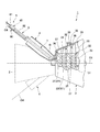
- the inspection device 5 of this embodiment includes an inspection cable 61, an inspection tube 6, a guide jig 7, a drive control device (inspection tube drive control device) 8, a camera image monitor 91, and a self-position. And a display monitor 92.
- the inspection cable 61 has a highly flexible cable body 611 and a sensor 612 provided at the tip of the cable body 611 and capable of inspecting the inside of the turbine 3.
- the cable main body 611 is bendable in an arbitrary direction intersecting with the cable extending direction, which is the extending direction of the cable main body 611, by an operator operating an operation unit (not shown).
- a member different from the tube 62 and is detachably fixed to the tube 62.
- the cable body 611 is provided with an actuator (not shown) for moving the cable so that it can be driven independently of the inspection tube 6.
- the sensor 612 is fixed to the tip of the cable body 611.
- the sensor 612 and the cable body 611 are built in the tube 62.
- the sensor 612 of the present embodiment is a camera capable of capturing an image of the inside of the turbine 3.
- Imaged data such as an image and an image captured by the sensor 612 is sent to the camera image monitor 91 via a cable extending from the end (rear end) of the cable body 611 on the side where the sensor 612 is not provided.
- a borescope industrial endoscope
- the inspection cable 61 may be any cable having a bendable structure, and may be, for example, a serpentine robot having a multi-joint structure in which a plurality of highly flexible members are connected.
- the senor 612 is not limited to being a camera as in the present embodiment.
- the sensor 612 of the present embodiment may be a sensor 612 having a dimension measurement function (for example, three-dimensional phase measurement) or a sensor 612 capable of measuring temperature and the presence / absence of scratches.
- the inspection tube 6 includes a tube 62, a posture actuator 65, and an advancing / retreating actuator 67.
- the tube 62 has a hollow portion inside which the inspection cable 61 can be inserted.
- the tube 62 has flexibility.
- the tube 62 has a multi-joint structure that can be bent at a plurality of points. Therefore, the tube 62 can be bent in any direction intersecting with the tube extending direction, which is the extending direction of the tube 62.
- each joint portion of the tube 62 has a structure that is easy to bend, but is hard to be twisted and compressed.
- the outer diameter of the tube 62 is set to a size that can be inserted into the narrow portion ⁇ (see FIG. 14) in the combustor 4 and between the moving and stationary blades of the turbine 3.
- a cable body 611 is attachable to and detachable from the tube 62.
- the tube 62 of the present embodiment is configured by connecting a plurality of tube bodies 63.
- the plurality of tube bodies 63 are arranged side by side in the extending direction of the tube body 63 and are connected to each other.
- the tube main body 63 can be deformed into a deformed state in which it is deformed to be bent from an initial state in which it is linearly extended along the central axis thereof.
- the tube main body 63 has a tubular portion 631 having both ends open, and a flange portion 632 projecting radially outward from the outer peripheral surfaces of both ends of the tubular portion 631. ..
- the tubular portion 631 has a cylindrical shape into which the inspection cable 61 can be inserted.
- the tubular portion 631 has, for example, a plurality of slits (not shown) formed therein and can be bent in any direction.
- the flange portion 632 is formed in an annular shape and is integrally formed with the tubular portion 631.
- the attitude actuator 65 is capable of adjusting the attitude of the tube 62.
- the posture of the tube 62 is the position and orientation of the tip of the tube 62 on an imaginary plane intersecting the tube extension direction.
- the attitude actuator 65 of this embodiment is fixed to the rear end of the tube 62.
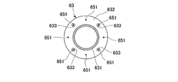
- the posture actuator 65 has a plurality of wires 651, a housing portion 652, a pulley 653, a wire drive portion 654, and a wire load detection portion 655.
- a plurality of wires 651 are provided for one tube body 63 (for example, four wires in this embodiment).
- the tip of the wire 651 is fixed to the flange portion 632 located on the tip side of the tube body 63.
- the wires 651 are fixed apart from each other so as to shift the phase with respect to one flange portion 632 (for example, 90 degrees).
- the wires 651 are arranged such that the phases of the adjacent tube bodies 63 are shifted. Therefore, as shown in FIG. 6, for example, the fixing position of the wire 651 is shifted by 45 degrees from the one tube main body 63 arranged on the distal end side in the other tube main body 63 adjacent on the rear end side.
- the flange portion 632 of the tube body 63 on the rear end side is formed with a wire insertion hole 633 for inserting the wire 651 fixed to the tube body 63 arranged on the tip side of the tube body 63. ing. Therefore, the wire insertion holes 633 are formed in larger numbers in the tube main body 63 arranged at the position closest to the rear end.
- the casing 652 is fixed to the rear end of the tube 62.
- the housing 652 accommodates one end of the wire 651 therein.
- the housing portion 652 is formed with a housing through hole 652A through which the cable body 611 protruding from the rear end of the tube 62 can be inserted.
- the housing through hole 652A is formed so as to penetrate the housing 652.
- the pulley 653 is rotatably attached inside the housing 652.
- the pulley 653 reverses the direction in which the wire 651 extends inside the housing 652.
- the pulley 653 is provided for each wire 651. That is, one pulley 653 is provided for each wire 651.
- a plurality of pulleys 653 are provided separately from each other so as to surround the housing through hole 652A.
- the wire driving unit 654 is fixed inside the housing 652.
- the wire drive unit 654 is provided for each wire 651. That is, one wire driving unit 654 is provided for each wire 651.
- the wire drive unit 654 is connected to the rear end of the wire 651, which is the end of the wire 651 that is not fixed to the tube body 63, via the wire load detection unit 655.
- the wire driving unit 654 can move the wire 651 forward and backward with respect to the pulley 653.
- an electric slider, an electric cylinder, or a ball screw is used as the wire driving unit 654.
- the wire load detection unit 655 is arranged between the rear end of the wire 651 and the wire drive unit 654.
- the wire load detection unit 655 measures the load (wire pulling force) generated on the wire 651, and sends the measurement result to the wire drive unit 654.
- the wire driving unit 654 is driven to loosen the wire 651.
- the wire driving unit 654 stretches the wire 651 so as not to loosen it. Driven.
- the wire load detection unit 655 may be, for example, a load cell capable of directly measuring the load. Further, as an alternative, the load may be indirectly measured based on the motor current value in the wire driving unit 654.
- the posture actuator 65 drives a part of the tube main bodies 63 among the plurality of tube main bodies 63, which is arranged at a position close to the tip.
- the tube main body 63 driven by the posture actuator 65 may be one or plural.
- the tube 62 of the present embodiment is divided into an active portion 62A driven by the posture actuator 65 and a driven portion 62B that is not driven (deformed or moved) by the posture actuator 65.
- the wire 651 is fixed to the flange portion 632 of each tube body 63.
- the active portion 62A is a region of the tube 62 having a predetermined length from the tip.
- the predetermined length is a length that can reach a desired inspection range.
- the driven unit 62B moves following the movement of the active unit 62A.
- the wire 651 is not fixed to the flange portion 632 of each tube body 63.
- the driven portion 62B is an area from the rear end of the tube 62 to the active portion 62A.
- the driven portion 62B of the present embodiment is a region sandwiched between the housing portion 652 and the active portion 62A.
- the advancing / retreating actuator 67 is capable of advancing / retreating the tube 62.
- the forward / backward movement of the tube 62 is to move the tube 62 in the tube extending direction.
- the advancing / retreating actuator 67 of the present embodiment can move the casing 652 to which the tube 62 is fixed.
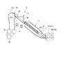
- the advancing / retreating actuator 67 has a guide rail 672 and an advancing / retreating drive unit 671.
- the guide rail 672 can be fixed to the upstream end of the combustor 4 via the guide jig 7.
- the guide rail 672 of the present embodiment is fixed to the combustor 4 and extends parallel to the virtual central axis O4 of the portion including the upstream end of the combustion tube 41.
- the advancing / retreating drive unit 671 moves on the guide rail 672.
- a housing 652 is fixed to the advancing / retreating drive unit 671.
- the advancing / retreating drive unit 671 is, for example, an electric slider.
- FIG. 8 As the advancing / retreating drive unit 671 moves on the guide rail 672 so as to approach the connection position with the combustor 4, the tube 62 is inserted deep inside the turbine 3 (downstream side). ..
- the tube 62 moves from the inner side of the turbine 3 to the inlet of the turbine 3. It is moved to the vicinity (upstream side).
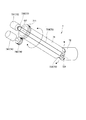
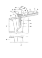
- the guide jig 7 guides the tube 62 from the outside of the gas turbine 1 to the inside of the turbine 3.
- the guide jig 7 of the present embodiment is inserted into the combustion cylinder 41 from the upstream side of the combustor 4, so that the tip of the tube 62 is provided outside the combustor 4 and at the outlet of the combustor 4 (inside the turbine 3). Guide to the vicinity of the upstream side of the first stage stationary blade 371).
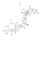
- the guide jig 7 has a guide tube 71, a head tube 72, a head tube rotating portion 73, and a guide tube rotating portion 74.
- the guide tube 71 extends along the central axis O7.
- the guide tube 71 is a cylindrical member into which the tube 62 can be inserted.
- the guide pipe 71 is formed to be longer than the length of the portion of the combustion cylinder 41 that includes the upstream end portion that extends along the virtual center axis O4.
- a leading tube 72 is connected to the tip of the guide tube 71.
- a guide pipe flange portion 711 is formed at the rear end of the guide pipe 71, which is opposite to the end portion on the side where the leading pipe 72 is provided.
- the guide pipe flange portion 711 is formed at the rear end of the guide pipe 71 so as to form an annular shape, and projects outward from the outer peripheral surface in the radial direction. Gears are formed on the outer peripheral surface of the guide pipe flange portion 711.
- the guide pipe 71 can be fixed to the combustor 4 with the guide pipe flange portion 711 positioned outside.
- the leading tube 72 is a cylindrical member into which the tube 62 can be inserted.
- the rear end of the head tube 72 is rotatably supported by the guide tube 71 via the head tube rotating shaft 721.
- the lead tube rotating shaft 721 extends in a direction orthogonal to the central axis O7.
- the head tube rotating shaft 721 rotatably connects the head tube 72 and the guide tube 71.
- the tip of the lead tube 72 is a free end.
- the leading tube 72 is formed shorter than the guide tube 71.
- the lead pipe 72 has a length that is approximately the same as the length of the portion of the combustion cylinder 41 that includes the downstream end.
- the head tube rotating unit 73 rotates the head tube 72 with respect to the guide tube 71.
- the head tube rotating portion 73 has a head tube rotating motor 731, a head tube side pulley 732, a motor side pulley 733, and a wire portion 734.
- the head tube rotation motor 731 is provided so as to be located outside the combustor 4 when the guide jig 7 is attached to the combustor 4.
- the head tube side pulley 732 is fixed to the head tube rotating shaft 721.
- the motor-side pulley 733 is fixed to the drive shaft of the leading tube rotation motor 731.
- the wire portion 734 has an endless shape and is stretched around the leading tube side pulley 732 and the motor side pulley 733.
- the head tube rotation motor 731 is driven, and the motor side pulley 733 rotates.
- the rotation of the motor-side pulley 733 is transmitted to the head tube side pulley 732 via the wire portion 734, and the head tube side pulley 732 rotates together with the head tube rotating shaft 721.
- the head tube 72 rotates about the head tube rotation axis 721.
- the guide tube rotating unit 74 rotates the guide tube 71 about the central axis O7.
- the guide tube rotating portion 74 has a guide tube rotating motor 741 and a guide tube rotating gear 742.
- the guide tube rotating motor 741 is arranged so that the guide tube rotating gear 742 meshes with the guide tube flange portion 711 outside the combustor 4 when the guide jig 7 is attached to the combustor 4.
- the guide tube rotating gear 742 is fixed to the drive shaft of the guide tube rotating motor 741. As a result, the guide tube rotation motor 741 is driven, and the guide tube rotation gear 742 rotates. As the guide tube rotating gear 742 rotates, the engaged guide tube flange portion 711 rotates. As a result, the guide tube 71 rotates with the leading tube 72 about the central axis O7.
- the drive control device 8 can send a signal to the posture actuator 65 and the advancing / retreating actuator 67 to control the movement of the tube 62.
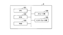
- the drive controller 8 is a computer including a CPU (Central Processing Unit) 101, a ROM (Read Only Memory) 102, a RAM (Random Access Memory) 103, a storage unit 104, and an interface unit 105. .. Signals are exchanged with the attitude actuator 65 and the advancing / retreating actuator 67, and a camera image monitor 91 and a self-position display monitor 92, which will be described later, via the interface unit 105.
- the CPU 101 is a processor that controls the entire operation of the drive control device 8.
- the CPU 101 performs various functions described later by operating according to a program prepared in advance.
- ROM 102 is a non-rewritable non-volatile memory.
- the RAM 103 is a rewritable volatile memory.
- the ROM 102 and the RAM 103 are also referred to as a main storage device, and a program for the CPU 101 to perform various functions and operate is expanded.
- the storage unit 104 is a large-capacity storage device (nonvolatile memory) built in the drive control device 8, and is, for example, a HDD (Hard Disk Drive), an SSD (Solid State Drive), or the like.
- the storage unit 104 is also called an auxiliary storage device, and stores necessary information such as three-dimensional shape data inside the turbine 3 described later, data obtained by a preliminary test and a simulation, and a program for operating the CPU 101. ing.
- the CPU 101 of the drive control device 8 executes a program stored in advance in the device itself to output the output unit 81, the route determination unit 82, the inverse analysis unit 83, the forward analysis unit 84, the correction unit 85, The functions of the position estimating unit 87 and the position correcting unit 88 are exhibited.
- the output unit 81 performs various controls such as drive control for starting and stopping the posture actuator 65 and the advancing / retreating actuator 67, and starting and ending each function of the drive control device 8.
- the output unit 81 outputs the information acquired by each functional unit to the posture actuator 65, the forward / backward actuator 67, and the self-position display monitor 92.
- the route determination unit 82 acquires the three-dimensional shape data of the inside of the turbine 3 stored in advance.
- the route determination unit 82 determines the route R based on the acquired three-dimensional shape data.
- the route R is a target to be inspected (inspected) from the starting point P1 at which the tip of the tube 62 is first arranged inside the turbine 3 in the inspection method S1 of the present embodiment, as shown in FIG. It is the route to point P2.
- the starting point P1 is the point where the tip of the tube 62 is located before the start of the inspection.
- the starting point P1 in the present embodiment is a connecting portion between the inlet of the turbine 3 and the outlet of the combustor 4, and is near the upstream end of the first stage vane 371.
- the target point P2 is an arbitrary inspection position inside the turbine 3, such as the stationary blade 37 and the moving blade 33, which are the inspection targets.
- the reverse analysis unit 83 performs an analysis of moving the tube 62 along the route R from the start point P1 to the target point P2 based on the information on the route R determined by the route determination unit 82.
- the inverse analysis unit 83 performs a simulation in which the tip of the tube 62 virtually advances along the route R so that the tube 62 does not come off the route R over the entire region.
- the forward analysis unit 84 analyzes the operation amount by which the posture actuator 65 and the forward / backward actuator 67 are operated when the tube 62 is positioned at each position on the route R, based on the analysis result of the inverse analysis unit 83. To get as.
- the correction unit 85 acquires the self-weight deflection amount of the tube 62 due to the self-weight of the tube 62.
- the correction unit 85 corrects the analysis operation amount based on the self-weight deflection amount.
- the self-weight deflection amount is an amount of downward movement in the vertical direction such as slack of the tube 62 caused by the weight of the tube 62.
- the position estimation unit 87 estimates the position and orientation of the tip of the tube 62 inside the turbine 3 based on the analysis operation amount and the information on the route R determined by the route determination unit 82.
- the imaging information captured by the sensor 612 is input to the position correction unit 88.
- the position correction unit 88 corrects the deviation of the actual position and orientation of the sensor 612 with respect to the position and orientation of the tube 62 estimated by the position estimation unit 87 based on the input imaging information.
- the camera image monitor 91 displays the image taken by the sensor 612. Imaging information captured by the sensor 612 is input to the camera image monitor 91 from the inspection cable 61. The image pickup information input to the camera image monitor 91 is sent to the self-position display monitor 92 and the drive control device 8.
- the self-position display monitor 92 displays the route R on the three-dimensional shape data inside the turbine 3 and the current position and posture of the tube 62.
- Information on the route R and information on the position and orientation of the tube 62 estimated by the position estimation unit 87 are input to the self-position display monitor 92 from the drive control device 8.
- the self-position display monitor 92 displays the estimated current position and orientation of the tube 62 on the route R based on the input information.
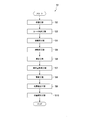
- the inspection method S1 using the inspection device 5 includes a preparation step S2, a route determination step S3, an inverse analysis step S4, a forward analysis step S5, a correction step S6, a manipulated variable acquisition step S7, a drive step S8, and a position estimation. It includes step S9 and position correction step S10.
- the inspection device 5 is prepared.
- the prepared inspection device 5 is attached to the combustor 4 of the gas turbine 1.
- the guide jig 7 is inserted into the combustion tube 41 from the upstream end of the combustor 4.
- the head tube rotating portion 73 causes the head tube 72 to be coaxial with the center axis O7 of the guide tube 71 so that the center axis of the head tube 72 is coaxial.
- 72 is rotated.
- the guide jig 7 is a portion where the tip of the leading tube 72 is bent in the combustion cylinder 41 (a region including an upstream end portion and a downstream end portion intersecting each other). It is inserted in the combustion cylinder 41 until it reaches.
- the leading tube 72 is rotated by the leading tube rotating portion 73 with respect to the guide tube 71 so that the central axis of the leading tube 72 approaches the horizontal without contacting the inner wall of the combustion tube 41.
- the guide jig 7 is further inserted into the combustion cylinder 41.
- the central axis of the lead pipe 72 becomes horizontal. That is, the leading tube 72 is parallel to the portion including the downstream end of the combustion cylinder 41.
- the guide pipe 71 is rotated by the guide pipe rotating portion 74 so that the tip of the leading pipe 72 faces the gap between the front edges of the first stage stationary blades 371 that are adjacent in the circumferential direction.
- the guide tube rotating section 74 is driven so as to be synchronized with the leading tube rotating section 73.
- the head tube 72 rotates in synchronization with the head tube rotation axis 721 while the guide tube 71 rotates about the central axis O7.
- the guide pipe 71 rotates while the leading pipe 72 always faces horizontally, and the tip of the leading pipe 72 faces the gap between the front edges of the first stage stationary blades 371 that are adjacent in the circumferential direction.
- the guide jig 7 is fixed to the combustor 4.
- the inspection tube 6 is fixed to the guide jig 7 in the preparation step S2. Specifically, the tube 62 fixed with the inspection cable 61 inserted therein is inserted into the guide jig 7 by the operator. At the same time, the guide rail 672 is fixed to the guide pipe flange portion 711. As a result, as shown in FIG. 2, in the state in which the advancing / retreating drive unit 671 is located at the lowest position with respect to the guide rail 672 (the position where the advancing / retreating drive unit 671 is farthest from the guide pipe flange 711). The tube 62 in the bent state is gradually extended so that the tip thereof is near the tip of the leading tube 72. As a result, as shown in FIG. 1, the tip of the tube 62 reaches the tip of the lead tube 72 and is arranged near the outlet of the combustion tube 41.
- the route determination unit 82 determines the route R along which the tube 62 moves from the starting point P1 to the target point P2. Specifically, as shown in FIG. 13, the route determination unit 82 stores the three-dimensional shape data, which is data on the shapes and arrangements of the moving blades 33 and the stationary blades 37 in each stage in the turbine casing 35, into the storage unit 104. To get from. The route determination unit 82 uses the acquired three-dimensional shape data as map information to determine a route R that does not contact the moving blade 33 or the stationary blade 37.
- the route determination unit 82 based on the acquired three-dimensional shape data, at least one of an intermediate position between the moving blades 33 adjacent in the circumferential direction and a central position between the stationary blades 37 adjacent in the circumferential direction.
- the route R is determined to pass through.
- the route R is determined so that the adjacent moving blades 33 (or the stationary blades 37) pass through the intermediate positions of the narrowed portions ⁇ having the narrowest intervals.
- the route R is determined so as to pass through the intermediate position of the adjacent moving blades 33 (or the stationary blades 37) over the entire region from the upstream side to the downstream side even in the region other than the narrow portion ⁇ . preferable.
- the reverse analysis unit 83 performs a simulation of moving the tube 62 on the route R. Specifically, the inverse analysis unit 83 bends the plurality of tube bodies 63 virtually on the three-dimensional analysis model so that the tube 62 is forcibly moved while being restrained on the route R. A simulation of moving the tip of the tube 62 from the starting point P1 to the target point P2 is performed. At this time, a simulation is performed so that the center of the front flange portion 632 of each tube body 63 in the active portion 62A passes along the route R. According to this simulation, the posture actuator 65 and the advancing / retreating actuator 67 are moved in reverse by the movement of the tube body 63.
- the operation amounts of the posture actuator 65 and the forward / backward actuator 67 are inversely analyzed.
- the operation amount of the posture actuator 65 is a movement amount by which the wire 651 in the wire driving unit 654 corresponding to each wire 651 is advanced and retracted for the purpose of changing the posture of the tube 62 (FIG. 7). reference). Therefore, when the operation amount of the posture actuator 65 changes, the stroke of each wire 651 becomes different. Therefore, by operating the posture actuator 65 so as to cause a stroke difference between the wires 651, the tip of the tube 62 can be brought into a desired posture.
- the operation amount of the forward / backward actuator 67 is the amount of movement of the forward / backward drive unit 671 with respect to the guide rail 672 for the purpose of moving the tube 62 forward / backward with respect to the start point P1 (see FIG. 7).
- the forward analysis is performed by the forward analysis unit 84, and the amount of operation is such that the posture actuator 65 and the advancing / retreating actuator 67 are moved as the tube 62 moves in the simulation in the inverse analysis unit 83.
- a certain manipulated variable is acquired. Specifically, when the tip of the tube 62 is located at a certain point on the route R, the wire drive section 654 corresponding to the wire 651 fixed to each tube body 63 in the active section 62A and the forward / backward drive section 671 are moved. The displacement of each is calculated. By calculating these displacements at a plurality of points on the route R, the manipulated variables of the posture actuator 65 and the advancing / retreating actuator 67 at arbitrary points on the route R are acquired. In the forward analysis step S5, this manipulated variable is acquired as the analysis manipulated variable.
- the correction unit 85 corrects the deviation of the tube 62 from the route R due to its own weight. Since the actual tube 62 has a certain weight, the weight may cause the tube 62 to slacken, and even if the tube 62 is moved according to the simulation, the tube 62 may deviate from the route R. Therefore, in the correction step S6, the movement amount (shift amount) caused by the own weight of the tube 62 at each point on the route R is calculated as the own weight deflection amount. Specifically, the correction unit 85 corrects the analysis operation amount using, for example, PID control.
- the operation amount acquired by the forward analysis unit 84 does not consider the amount of self-deflection, so that the position of the tube main body 63 with respect to the route R (adjacent tube main body 63 A deviation occurs in the center position of the flange portion 632 between them.
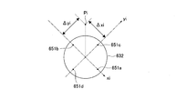
- the deviation amount ( ⁇ xi, ⁇ yi) from the point Pi on the route R in the i-th tube body 63 from the beginning is calculated based on the local coordinate system that can go to each tube body 63.
- this coordinate system is defined by the number and position of the wires 651 attached to the tube body 63.
- an xi axis passing through the first wire 651a and the second wire 651b and a yi axis passing through the third wire 651c and the fourth wire 651d are defined. It will be the reference coordinate system.
- the deviation amount ( ⁇ xi, ⁇ yi) is corrected by performing the PID control on the operation amount of each wire 651 based on the following equations (1) and (2).
- Kp, Ki, and Kd are correction coefficients.
- the correction according to the deviation amount ( ⁇ xi, ⁇ yi) is performed by the Kp term.
- the Ki term reduces the steady-state deviation of the deviation amount ( ⁇ xi, ⁇ yi).
- the Kd term can improve the response and reduce the deviation.
- the shift amount ( ⁇ xi) on the xi axis is a negative value (shifts to the second wire 651b side)
- the second wire 651b on the xi axis is pulled and the tube
- the flange portion 632 of the main body 63 moves toward the upper left in FIG. 16
- the shift amount ( ⁇ xi) on the xi axis becomes smaller.
- the deviation amount ( ⁇ yi) on the yi axis is a positive value (deviation toward the third wire 651c side)
- the third wire 651c on the yi axis is pulled, and the flange portion 632 of the tube body 63 is moved to the position shown in FIG.
- the amount of deviation ( ⁇ yi) on the yi axis becomes smaller by moving it toward the upper right corner of.
- the correction unit 85 may further correct the analysis operation amount so as to reduce the binding force.
- FIG. 17 is a feedback model taking two adjacent tube bodies 63 as an example.
- the first (top) tube body 63a and the second tube body 63b are referred to in order from the top.
- the binding force at the tip of the first tube body 63a is multiplied by P times the pre-tension, which is the minimum amount of wire tension required to keep the wire 651 in the first tube body 63a from loosening. Is added to generate the cable1 operation force of the first tube body 63a.
- a process X in which the resistance value (loss such as friction) generated in the wire 651 is reduced is applied to this, and a wire operation force f 63a at the tip of the first tube body 63a is generated.
- the wire operating force f 63a at the tip of the first tube body 63a is smaller than the cable1 operating force of the first tube body 63a by the amount of friction between the wire 651 and the flange portion 632.
- a binding force at the tip of the first tube body 63a is generated by the wire operating force f63a and the mechanical analysis (internal dynamic model Y). This logic is feedback-controlled so that the restraining force at the tip of the first tube body 63a approaches the target value 0.
- the cable1 operating force in the front first tube main body 63a is added, and the tip of the second tube main body 63b is added.
- the wire operating force f 63b is calculated, and feedback control is performed so that the binding force at the tip of the second tube body 63b approaches the target value 0.
- the corrected analysis operation amount is acquired as the operation amount of the posture actuator 65 and the advancing / retreating actuator 67, respectively.
- the output actuator 81 drives the posture actuator 65 and the forward / backward actuator 67.
- the information on the acquired operation amount is sent from the output unit 81 to the posture actuator 65 and the forward / backward actuator 67, and the posture actuator 65 and the forward / backward actuator 67 are driven respectively.
- the advance / retreat drive unit 671 moves on the guide rail 672, and the wire drive unit 654 moves the wire 651.
- the tube 62 passes through between the stationary blades 37 and the moving blades 33 and penetrates deep into the turbine 3.
- the tip of the actual tube 62 moves from the starting point P1 toward the target point P2.
- the position estimating unit 87 estimates the position and orientation of the tip of the tube 62 inside the turbine 3 after moving to the target point P2.
- the image pickup information picked up by the sensor 612 is input to the position correction unit 88.
- the position correction unit 88 analyzes and acquires virtual image data that should be seen by the sensor 612 at the position and orientation estimated in the position estimation step S9 based on the analysis operation amount and the information of the route R and the three-dimensional shape data. To do.
- the position correction unit 88 collates the acquired virtual image data with the input imaging information.
- the position correction unit 88 calculates the operated amounts of the posture actuator 65 and the advancing / retreating actuator 67 for moving the position and posture of the tube 62 so that the imaging information matches the virtual image data.
- the attitude actuator 65 and the advancing / retreating actuator 67 are driven based on the calculated operated amount, so that the actual position and attitude of the sensor 612 deviate from the estimated position and attitude of the tube 62. Is corrected. That is, the actual position and orientation of the sensor 612 are matched with the estimated position and orientation of the tube 62. As a result, the tip of the tube 62 reaches the position corresponding to the target point P2 inside the actual turbine 3.
- the tip of the tube 62 or the tip of the inspection cable 61 (sensor 612) is moved to widen the inspection range and the inspection is performed. Specifically, when moving the tip of the tube 62, an operator operates an operation unit (not shown) while confirming the image on the camera image monitor 91 and the display content on the self-position display monitor 92. As a result, a signal is sent from the output unit 81 to the posture actuator 65 so that the adjacent tube bodies 63 perform different movements.
- the posture actuator 65 moves the tip of the tube 62 so as to bend it. That is, the tube 62 is moved so as to change the direction in which the tip of the tube 62 faces.
- each tube main body 63 is affected by the movement of the wire 651 of each tube main body 63, and a predetermined curvature deformation is bent. To move.
- this characteristic and moving the wires 651 with respect to the adjacent tube bodies 63 with different operation amounts only the tip of the tube 62 is moved so as to bend.
- first (top) tube body 63a a first (top) tube body 63a
- second tube body 63b a second tube body 63b
- third tube body 63c a fourth tube body 63d
- fourth tube body 63d a fourth tube body 63d in order from the beginning.
- the operation amount of the wire 651 that moves the first tube body 63a upward in FIG. 18 is ⁇ d
- the second tube body 63b is on the opposite side to the movement of the first tube body 63a.
- the wire 651 is moved by the same operation amount ⁇ d so as to move downward.
- the movement from the second tube body 63b to the root is offset, and only the tip of the first tube body 63a is moved so as to bend.
- the posture actuator 65 translates the tip of the tube 62 along an imaginary plane orthogonal to the tube extending direction. That is, not only the tip of the tube 62 is swung so as to simply change the direction in which the tip of the tube 62 faces, but the tube 62 is moved so that the tip of the tube 62 moves up and down or left and right while looking at a certain direction. Is moved. Specifically, when the operation amount of the wire 651 that moves the first tube body 63a downward in FIG. 19 is ⁇ d, the movement of the second tube body 63b is opposite to that of the first tube body 63a.
- the wire 651 is moved by an operation amount 2 ⁇ d that is twice the operation amount on the first tube body 63a so as to move to the upper side which is the side. Further, in the third tube body 63c, the wire 651 is moved by the same operation amount ⁇ d so as to move downward like the movement of the first tube body 63a. As a result, the bending of the first tube body 63a is offset, the first tube body 63a moves laterally, and the tip of the first tube body 63a moves in parallel.
- the worker When moving the inspection cable 61, for example, the worker releases the fixing of the cable body 611 to the tube 62 after reaching the target point P2. After that, the operator operates the cable body 611 with the operation unit (not shown) while checking the image on the camera image monitor 91 and the display content on the self-position display monitor 92. As a result, the cable body 611 advances from the tip of the tube 62. At that time, as in the case of the tube 62, the tip of the cable body 611 may be moved so as to bend the neck. Thereby, the inspection range can be expanded and the inspection can be performed.
- the inverse analysis unit 83 performs a simulation of moving the tube 62 along the route R, and the forward analysis unit 84 acquires the analysis operation amount based on the simulation result. Therefore, the operation amount of the posture actuator 65 and the advancing / retreating actuator 67 required to move the tube 62 along the determined route R can be grasped as the analysis operation amount.
- a plurality of stationary blades 37 and moving blades 33 having a complicated shape are arranged side by side in the circumferential direction and the axis O1 direction in addition to being invisible. Therefore, the route R to the target point P2 becomes very complicated.
- the analysis operation amount is acquired, so that contact with obstacles such as the moving blades 33 and the stationary blades 37 is suppressed, and the tube 62 is appropriately set inside the turbine 3. Can be moved. Therefore, the tip of the tube 62 can reach the target point P2 with high accuracy without damaging the inside of the turbine 3. This allows the tube 62 to reach the target inspection position deeply with high accuracy even in a region where it is difficult to visually recognize.
- the route R that takes advantage of the characteristics of the tube 62 having multiple degrees of freedom is determined in advance, and the tube 62 is moved according to the determined route R. Therefore, before the tube 62 reaches the target point P2 inside the turbine 3, the tube 62 comes into contact with the moving blade 33 or the stationary blade 37 at the narrow portion ⁇ to cause clogging or catching, which prevents the tube 62 from proceeding further.
- the inspection can be performed while suppressing the occurrence of defects. As a result, even in an area where visual recognition is difficult, it is possible to perform inspection with high accuracy using the sensor 612 without opening the turbine casing 35.
- the route determination unit 82 determines the route R based on the three-dimensional shape data inside the turbine 3. Therefore, a highly accurate route R is determined based on accurate information inside the turbine 3. Therefore, the tube 62 can be moved along the accurate route R to the target point P2. Therefore, it is possible to suppress contact with the moving blades 33, the stationary blades 37, and the like when the tube 62 is moved inside the turbine 3.
- the route R is determined so that the moving blades 33 and the stationary blades 37 adjacent to each other pass through the intermediate position of the narrow portion ⁇ having the narrowest space. Therefore, when the tube 62 actually moves, even if it slightly deviates from the route R, it does not come into contact with the moving blades 33 or the stationary blades 37. Therefore, it is possible to further suppress contact with an obstacle when the tube 62 is moved inside the turbine 3. As a result, damage to the moving blades 33 and the stationary blades 37 due to the movement of the tubes 62 inside the turbine 3 can be suppressed.
- the movement amount due to the weight of the tube 62 is corrected by the correction unit 85. Therefore, the influence of the actual weight of the tube 62 can be suppressed, and the tube 62 can be moved in a form close to the result of the simulation by the inverse analysis unit 83. Therefore, the tube 62 can be moved with higher accuracy.
- the position correction unit 88 acquires the operation amounts of the attitude actuator 65 and the advancing / retreating actuator 67 for adjusting the actual position and attitude of the sensor 612 to the estimated position and attitude of the sensor 612. You can As a result, it is possible to correct the actual position and posture deviation of the tube 62. Therefore, it is possible to move the tube 62 to the target point P2 on the simulation with higher accuracy.
- the tip of the tube 62 can be moved in parallel along an imaginary plane orthogonal to the tube extending direction. Therefore, it is possible to move the sensor 612 in parallel to the blade surfaces of the moving blades 33 and the stationary blades 37, so that obstacles can be avoided efficiently and the inspection range can be expanded.
- the cable body 611 can be attached to and detached from the tube 62. Therefore, after the tip of the tube 62 reaches the target point P2, the inspection cable 61 provided with the sensor 612 at the tip can be moved with respect to the tube 62. As a result, the field of view near the target point P2 can be expanded and the inspection range can be expanded.
- the inspection tube 6 is inserted into the turbine 3 via the guide jig 7 having the leading tube 72 rotating with respect to the guide tube 71.
- the head tube 72 is rotatable with respect to the guide tube 71, so that the head tube 72 can be inserted deep into the combustion cylinder 41 having a structure that bends in the middle. Therefore, the leading tube 72 can reach the outlet of the combustion cylinder 41 without damaging the combustion cylinder 41.
- the tube 62 can easily reach the inlet of the turbine 3 from the upstream side of the combustor 4 simply by inserting the tube 62 into the guide jig 7.
- the leading tube 72 can be kept horizontal while adjusting the circumferential direction of the tip of the leading tube 72. Therefore, it becomes easy to set the starting point P1 to a desired position. Since the starting point P1 can be set at a desired position, the tube 62 can easily reach deep inside the turbine 3.
- the inspection device 5 is installed so that the tube 62 is inserted from the upstream side of the combustor 4, but the inspection device 5 is not limited to such installation.
- the inspection device 5 may be installed so that the tube 62 is inserted through the inspection port 38 formed on the side surface of the turbine casing 35.
- the shape of the guide tube 70 of the guide jig 7 of the modified example is not limited to the shape of the embodiment, and may be a linear pipe.
- the operator operates the camera.
- the cable body 611 is operated by the operation unit (not shown) while confirming the image on the image monitor 91 and the display content on the self-position display monitor 92.
- the cable body 611 advances from the tip of the tube 62.
- the cable main body 611 is moved so as to wrap around the turbine rotor 31 in the circumferential direction, and reaches the moving blades 33 and the stationary blades 37 arranged near the side opposite to the inspection port 38 in the circumferential direction. In this way, regardless of the position of the inspection port 38, it is possible to inspect the moving blade 33 and the stationary blade 37 arranged at any position in the circumferential direction.
- the posture actuator 65 is fixed to the guide tube 70 via the heat insulating material 21 formed of a material having a lower thermal conductivity than the guide tube 70. It may have been done. As a result, the heat of the turbine casing 35 can be prevented from being transferred to the posture actuator 65 and the tube 62.
- the inspection apparatus may further include a coolant injection unit 22 that injects a coolant toward the heat insulating material 21.
- the coolant injection unit 22 is capable of injecting a coolant such as dry ice powder or air toward the heat insulating material 21.
- the heat insulating material 23 is formed of a material that makes it difficult to transfer the heat of the turbine casing 35 to the camera image monitor 91, the self-position display monitor 92, and the drive control device 8.
- the heat insulating material 23 may be the same material as the heat insulating material 21.
- the space for installing the camera image monitor 91, the self-position display monitor 92, and the drive control device 8 can be reduced. Therefore, it is not necessary to secure a large space around the turbine 3. Furthermore, by mounting the heat insulating material 23 on the turbine casing 35, it is possible to prevent heat of the turbine casing 35 from being transmitted to the camera image monitor 91, the self-position display monitor 92, and the drive control device 8.
- the inspection cable 61 is not limited to the structure of the above-described embodiment.
- the inspection cable 610 may further include a sheath 613 that covers the cable body 611, and a cooling fluid supply unit 614 that supplies a cooling fluid to the inside of the sheath 613.
- the sheath 613 has a tubular shape. Inside the sheath 613, the cable main body 611 is fixed while being inserted. That is, the sheath 613 can be moved and bent together with the cable body 611.
- the sheath 613 is made of a material having a lower thermal conductivity than the cable body 611.
- the end of the sheath 613 on the rear side is closed by a seal 615.
- the front end of the sheath 613 (position near the sensor 612) is open.
- the cooling fluid supply unit 614 supplies the cooling fluid to the gap between the inner peripheral surface of the sheath 613 and the outer peripheral surface of the cable body 611.
- the supplied cooling fluid is, for example, cooling air used for the turbine 3.
- the cooling fluid supply unit 614 includes a cooling fluid supply source 616, a cooler 617 that cools the cooling air sent from the supply source 616, and a regulator 618 that regulates the cooling air cooled by the cooler 617. There is.
- the sheath 613 By having the sheath 613, it becomes difficult to transmit the temperature of the high temperature gas flowing inside the turbine 3 to the cable main body 611 arranged inside. Further, the cooling fluid is supplied to the inside of the sheath 613 by the cooling fluid supply unit 614, so that the cooling fluid flows between the inner peripheral surface of the sheath 613 and the outer peripheral surface of the cable body 611. As a result, the cable body 611 is cooled by the cooling fluid. The cooling fluid that has cooled the cable body 611 is discharged into the turbine 3 through the opening on the front side of the sheath 613. By cooling the cable body 611, it is possible to prevent the cable body 611 from reaching a high temperature due to the surrounding environment. As a result, even if the inside of the turbine 3 is at a high temperature, such as immediately after the turbine 3 has stopped, damage to the cable body 611 can be suppressed and inspection can be performed.
- the active portion 62A is arranged in the front area (the area of the tube 62 having a predetermined length from the tip), and the driven area 62B is provided in the rear area (the area of the tube 62 from the rear end to the active portion 62A).
- the structure to be arranged is not limited.
- the active portions 62A and the driven portions 62B may be alternately arranged in the extending direction of the tube 620.
- the driven portion 62B is not limited to the structure in which the driven portion 62B simply moves by following the movement of the active portion 62A.
- the driven portion 620B may have a structure that can be restored by an elastic force from the deformed state in which the driven portion 620B is deformed following the movement of the active portion 62A to the initial state.
- the tube body 630 further includes a plurality of (for example, four in this embodiment) springs 634.
- the spring 634 connects the flange portions 632 at both ends outside the tubular portion 631.
- the spring 634 is a tension spring that exerts a tensile force that pulls the flange portions 632 at both ends together.
- the plurality of springs 634 are arranged at equal intervals in the circumferential direction.
- the driven portion 620B is not limited to generating a restoring force for returning to the initial state by the spring 634.
- the driven portion 620B may have any structure as long as the structure has elastic force.
- a rubber material may be used instead of the spring 634, and the tubular portion 631 itself may be made of an elastically deformable material.
- the tube 62 is not limited to the structure having a plurality of tube bodies 63 as in the present embodiment.
- the tube 62 may have a multi-joint structure that can be bent at a plurality of points by, for example, a structure in which pin joints are stacked while changing the phase by 90 degrees or a structure in which spherical joints are stacked.
- the inspection object is not limited to the turbine 3 of the gas turbine 1 as in the present embodiment.
- the portion to be inspected may be one that has a region that is difficult to visually recognize, such as an object whose inside is blocked.
- the inspection object may be the compressor 2 or the combustor 4 in the gas turbine 1, or a rotary machine other than the gas turbine 1 such as a steam turbine.
- the inspection cable 61 and the inspection tube 6 are not limited to being separate detachable members as in the present embodiment. That is, the inspection cable 61 and the inspection tube 6 may be a single member that is non-detachably fixed.
- the tube 62 may be further provided with another detection device equipped with a small-sized MEMS inertial sensor (for example, a triaxial gyro and a triaxial accelerometer).
- a small-sized MEMS inertial sensor for example, a triaxial gyro and a triaxial accelerometer.
- the route R used for analysis by the inverse analysis unit 83 is not limited to being determined by the route determination unit 82.
- the route R may be previously determined separately by an operator or the like and input from the outside.
- the route determination unit 82 is not limited to automatically determining the route R in advance.
- the route R may be determined to be revised based on an instruction from the operator (for example, operating the operation unit) while the tube 62 is moving. Specifically, when the operator inputs a new target point, the route determination unit 82 immediately generates the route R from the start point P1 to the new target point.
- the analysis operation amount may be calculated by reverse analysis in the reverse analysis unit 83 or forward analysis in the forward analysis unit 84.
- the position correction unit 88 is not limited to automatically correcting the position and orientation based on the imaging information acquired by the sensor 612.
- the position correction step S10 when the operator confirms the image on the camera image monitor 91 and the display content on the self-position display monitor 92 and feels that the operator deviates from the route R, or contacts an obstacle such as a wing. When it feels like to do so, the operator may operate the operation unit (not shown) to move the tube 62 and the inspection cable 61 to correct the position and orientation.
- the route R is determined so as to pass through at least one of an intermediate position between the moving blades 33 adjacent in the circumferential direction and a central position between the stationary blades 37 adjacent in the circumferential direction. It is not limited to.
- the route R may be determined so that the tube 62 winds around the moving blade 33 or the stationary blade 37.
- the position retention of the tube 62 inside the turbine 3 is improved. Therefore, when the inspection cable 61 is moved so as to extend from the tip of the tube 62, the sensor 612 can be moved in a stable state.
- a program for realizing all or some of the functions of the drive control device 8 in the present invention is recorded in a computer-readable recording medium, and the program recorded in this recording medium is read into a computer system and executed. By doing so, all or part of the processing performed by the drive control device 8 may be performed.
- the “computer system” mentioned here includes an OS and hardware such as peripheral devices.
- the “computer system” also includes a WWW system having a homepage providing environment (or display environment).
- the “computer-readable recording medium” refers to a portable medium such as a flexible disk, a magneto-optical disk, a ROM, a CD-ROM, or a storage device such as a hard disk built in a computer system.
- the "computer-readable recording medium” is a volatile memory (RAM) inside a computer system that serves as a server or a client when a program is transmitted via a network such as the Internet or a communication line such as a telephone line.
- RAM volatile memory
- those that hold the program for a certain period of time are also included.
- the above program may be transmitted from a computer system that stores the program in a storage device or the like to another computer system via a transmission medium or by a transmission wave in the transmission medium.
- the "transmission medium” for transmitting the program refers to a medium having a function of transmitting information such as a network (communication network) such as the Internet or a communication line (communication line) such as a telephone line.
- the program may be for realizing a part of the functions described above. Further, it may be a so-called difference file (difference program) that can realize the above-mentioned functions in combination with a program already recorded in the computer system.
- the tube can reach the target inspection position with high accuracy even in a region where it is difficult to visually recognize.
Landscapes
- Engineering & Computer Science (AREA)
- Chemical & Material Sciences (AREA)
- Combustion & Propulsion (AREA)
- Mechanical Engineering (AREA)
- General Engineering & Computer Science (AREA)
- Physics & Mathematics (AREA)
- General Physics & Mathematics (AREA)
- Life Sciences & Earth Sciences (AREA)
- Analytical Chemistry (AREA)
- Biochemistry (AREA)
- General Health & Medical Sciences (AREA)
- Immunology (AREA)
- Pathology (AREA)
- Health & Medical Sciences (AREA)
- Investigating Materials By The Use Of Optical Means Adapted For Particular Applications (AREA)
Abstract
Ce dispositif de commande d'entraînement de tube d'inspection comprend : une unité d'analyse inverse (83) qui effectue une analyse afin de déplacer un tube flexible le long d'un itinéraire prédéterminé à l'intérieur d'un objet inspecté, d'un point de départ à un point cible de l'itinéraire ; et une unité d'analyse prospective (84) qui, sur la base des résultats provenant de l'unité d'analyse inverse (83), acquiert, en tant qu'analyse de grandeurs de fonctionnement, des grandeurs de fonctionnement pour un actionneur d'attitude capable de régler l'attitude du tube lorsque celui-ci est positionné sur chaque emplacement de l'itinéraire, et un actionneur d'avance et de recul qui fait avancer et reculer le tube.
Priority Applications (4)
| Application Number | Priority Date | Filing Date | Title |
|---|---|---|---|
| CN201980067810.XA CN112840204A (zh) | 2018-10-31 | 2019-10-31 | 检查用管的驱动控制装置、检查装置、检查方法、检查装置的程序及引导夹具 |
| EP19880347.0A EP3848698A4 (fr) | 2018-10-31 | 2019-10-31 | Dispositif de commande d'entraînement de tube d'inspection, dispositif et procédé d'inspection, programme pour dispositif d'inspection et gabarit de guidage |
| JP2020554023A JP7059396B2 (ja) | 2018-10-31 | 2019-10-31 | 検査用チューブの駆動制御装置、検査装置、検査方法、及び検査装置のプログラム |
| US17/231,509 US20210231530A1 (en) | 2018-10-31 | 2021-04-15 | Inspection tube drive control device, inspecting device, inspecting method, program for inspecting device, and guide jig |
Applications Claiming Priority (2)
| Application Number | Priority Date | Filing Date | Title |
|---|---|---|---|
| JP2018-205303 | 2018-10-31 | ||
| JP2018205303 | 2018-10-31 |
Related Child Applications (1)
| Application Number | Title | Priority Date | Filing Date |
|---|---|---|---|
| US17/231,509 Continuation US20210231530A1 (en) | 2018-10-31 | 2021-04-15 | Inspection tube drive control device, inspecting device, inspecting method, program for inspecting device, and guide jig |
Publications (1)
| Publication Number | Publication Date |
|---|---|
| WO2020090959A1 true WO2020090959A1 (fr) | 2020-05-07 |
Family
ID=70463286
Family Applications (1)
| Application Number | Title | Priority Date | Filing Date |
|---|---|---|---|
| PCT/JP2019/042729 Ceased WO2020090959A1 (fr) | 2018-10-31 | 2019-10-31 | Dispositif de commande d'entraînement de tube d'inspection, dispositif et procédé d'inspection, programme pour dispositif d'inspection et gabarit de guidage |
Country Status (5)
| Country | Link |
|---|---|
| US (1) | US20210231530A1 (fr) |
| EP (1) | EP3848698A4 (fr) |
| JP (1) | JP7059396B2 (fr) |
| CN (1) | CN112840204A (fr) |
| WO (1) | WO2020090959A1 (fr) |
Cited By (6)
| Publication number | Priority date | Publication date | Assignee | Title |
|---|---|---|---|---|
| US20210363897A1 (en) * | 2020-05-22 | 2021-11-25 | Raytheon Technologies Corporation | Thermal insulation features for gas turbine engines |
| JP2022115133A (ja) * | 2021-01-28 | 2022-08-09 | トヨタ自動車株式会社 | 検査装置 |
| JP2023112915A (ja) * | 2022-02-02 | 2023-08-15 | 三菱重工業株式会社 | 検査用ケーブル案内機構、駆動装置、検査用ケーブル挿入治具、及びこれらを備えているガスタービン検査システム |
| JP2023175241A (ja) * | 2022-05-30 | 2023-12-12 | 多摩川精機株式会社 | 管路計測装置 |
| US12325122B2 (en) | 2022-02-02 | 2025-06-10 | Mitsubishi Heavy Industries, Ltd. | Control device, inspection system, control method, and non-transitory computer-readable medium |
| WO2025121048A1 (fr) * | 2023-12-06 | 2025-06-12 | 三菱重工業株式会社 | Dispositif de surveillance, dispositif d'inspection, procédé de surveillance et programme |
Families Citing this family (3)
| Publication number | Priority date | Publication date | Assignee | Title |
|---|---|---|---|---|
| DE102020106509B3 (de) * | 2020-03-10 | 2021-06-24 | Lufthansa Technik Aktiengesellschaft | Vorrichtung und Verfahren für die Boroskopinspektion von technischen Geräten |
| CN115452862A (zh) * | 2022-05-24 | 2022-12-09 | 贵州电网有限责任公司 | 一种电缆排管检测用挠性内窥镜装置 |
| US20250332704A1 (en) * | 2024-04-30 | 2025-10-30 | General Electric Company | Insertion tool with rotation interface |
Citations (10)
| Publication number | Priority date | Publication date | Assignee | Title |
|---|---|---|---|---|
| JPH01216239A (ja) * | 1988-02-25 | 1989-08-30 | Olympus Optical Co Ltd | 管内自走式内視鏡 |
| JPH095640A (ja) * | 1995-06-19 | 1997-01-10 | Olympus Optical Co Ltd | 工業用内視鏡装置 |
| JP2000162157A (ja) | 1998-11-25 | 2000-06-16 | Mitsubishi Heavy Ind Ltd | 検査装置 |
| JP2008008881A (ja) * | 2006-06-26 | 2008-01-17 | Tokyo Electric Power Co Inc:The | 検査装置 |
| US20150054939A1 (en) * | 2013-08-21 | 2015-02-26 | Siemens Energy, Inc. | Internal inspection of machinery by stitched surface imaging |
| US20150341600A1 (en) * | 2014-05-22 | 2015-11-26 | Siemens Energy, Inc. | Flexible tether position tracking camera inspection system for visual inspection of off line industrial gas turbines and other power generation machinery |
| JP2015534046A (ja) * | 2012-08-23 | 2015-11-26 | シーメンス エナジー インコーポレイテッド | ラインから切り離した産業用ガスタービンおよび他の発電機械の目視検査および3d白色光走査のためのシステムおよび方法 |
| JP2017026508A (ja) * | 2015-07-24 | 2017-02-02 | 株式会社イチワ | 検査用撮影器具及び検査用撮影方法 |
| US20180209296A1 (en) * | 2015-02-06 | 2018-07-26 | Siemens Energy, Inc. | In-situ measurement of blade tip-to-shroud gap in turbine engine |
| JP2018205303A (ja) | 2017-06-02 | 2018-12-27 | オメガ・エス アー | 計時器用のパッケージング箱、計時器のテスト及び/又は時間合わせのためのデバイス |
Family Cites Families (4)
| Publication number | Priority date | Publication date | Assignee | Title |
|---|---|---|---|---|
| GB0020461D0 (en) * | 2000-08-18 | 2000-10-11 | Oliver Crispin Consulting Ltd | Improvements in and relating to the robotic positioning of a work tool to a sensor |
| US9116071B2 (en) * | 2012-01-31 | 2015-08-25 | Siemens Energy, Inc. | System and method for visual inspection and 3D white light scanning of off-line industrial gas turbines and other power generation machinery |
| JP6053358B2 (ja) * | 2012-07-03 | 2016-12-27 | オリンパス株式会社 | 手術支援装置 |
| JP6284688B2 (ja) * | 2015-06-29 | 2018-02-28 | 富士フイルム株式会社 | 撮像装置及び撮像方法 |
-
2019
- 2019-10-31 EP EP19880347.0A patent/EP3848698A4/fr not_active Withdrawn
- 2019-10-31 WO PCT/JP2019/042729 patent/WO2020090959A1/fr not_active Ceased
- 2019-10-31 CN CN201980067810.XA patent/CN112840204A/zh active Pending
- 2019-10-31 JP JP2020554023A patent/JP7059396B2/ja active Active
-
2021
- 2021-04-15 US US17/231,509 patent/US20210231530A1/en not_active Abandoned
Patent Citations (10)
| Publication number | Priority date | Publication date | Assignee | Title |
|---|---|---|---|---|
| JPH01216239A (ja) * | 1988-02-25 | 1989-08-30 | Olympus Optical Co Ltd | 管内自走式内視鏡 |
| JPH095640A (ja) * | 1995-06-19 | 1997-01-10 | Olympus Optical Co Ltd | 工業用内視鏡装置 |
| JP2000162157A (ja) | 1998-11-25 | 2000-06-16 | Mitsubishi Heavy Ind Ltd | 検査装置 |
| JP2008008881A (ja) * | 2006-06-26 | 2008-01-17 | Tokyo Electric Power Co Inc:The | 検査装置 |
| JP2015534046A (ja) * | 2012-08-23 | 2015-11-26 | シーメンス エナジー インコーポレイテッド | ラインから切り離した産業用ガスタービンおよび他の発電機械の目視検査および3d白色光走査のためのシステムおよび方法 |
| US20150054939A1 (en) * | 2013-08-21 | 2015-02-26 | Siemens Energy, Inc. | Internal inspection of machinery by stitched surface imaging |
| US20150341600A1 (en) * | 2014-05-22 | 2015-11-26 | Siemens Energy, Inc. | Flexible tether position tracking camera inspection system for visual inspection of off line industrial gas turbines and other power generation machinery |
| US20180209296A1 (en) * | 2015-02-06 | 2018-07-26 | Siemens Energy, Inc. | In-situ measurement of blade tip-to-shroud gap in turbine engine |
| JP2017026508A (ja) * | 2015-07-24 | 2017-02-02 | 株式会社イチワ | 検査用撮影器具及び検査用撮影方法 |
| JP2018205303A (ja) | 2017-06-02 | 2018-12-27 | オメガ・エス アー | 計時器用のパッケージング箱、計時器のテスト及び/又は時間合わせのためのデバイス |
Non-Patent Citations (1)
| Title |
|---|
| See also references of EP3848698A4 |
Cited By (10)
| Publication number | Priority date | Publication date | Assignee | Title |
|---|---|---|---|---|
| US20210363897A1 (en) * | 2020-05-22 | 2021-11-25 | Raytheon Technologies Corporation | Thermal insulation features for gas turbine engines |
| US11268404B2 (en) * | 2020-05-22 | 2022-03-08 | Raytheon Technologies Corporation | Thermal insulation features for gas turbine engines |
| JP2022115133A (ja) * | 2021-01-28 | 2022-08-09 | トヨタ自動車株式会社 | 検査装置 |
| JP7476814B2 (ja) | 2021-01-28 | 2024-05-01 | トヨタ自動車株式会社 | 検査装置 |
| JP2023112915A (ja) * | 2022-02-02 | 2023-08-15 | 三菱重工業株式会社 | 検査用ケーブル案内機構、駆動装置、検査用ケーブル挿入治具、及びこれらを備えているガスタービン検査システム |
| US12325122B2 (en) | 2022-02-02 | 2025-06-10 | Mitsubishi Heavy Industries, Ltd. | Control device, inspection system, control method, and non-transitory computer-readable medium |
| US12345871B2 (en) | 2022-02-02 | 2025-07-01 | Mitsubishi Heavy Industries, Ltd. | Inspection cable guide mechanism, driving device, inspection cable insertion jig, and gas turbine inspection system including these |
| JP7778311B2 (ja) | 2022-02-02 | 2025-12-02 | 三菱重工業株式会社 | 検査用ケーブル案内機構、駆動装置、検査用ケーブル挿入治具、及びこれらを備えているガスタービン検査システム |
| JP2023175241A (ja) * | 2022-05-30 | 2023-12-12 | 多摩川精機株式会社 | 管路計測装置 |
| WO2025121048A1 (fr) * | 2023-12-06 | 2025-06-12 | 三菱重工業株式会社 | Dispositif de surveillance, dispositif d'inspection, procédé de surveillance et programme |
Also Published As
| Publication number | Publication date |
|---|---|
| EP3848698A4 (fr) | 2021-11-24 |
| US20210231530A1 (en) | 2021-07-29 |
| JPWO2020090959A1 (ja) | 2021-09-16 |
| EP3848698A1 (fr) | 2021-07-14 |
| CN112840204A (zh) | 2021-05-25 |
| JP7059396B2 (ja) | 2022-04-25 |
Similar Documents
| Publication | Publication Date | Title |
|---|---|---|
| WO2020090959A1 (fr) | Dispositif de commande d'entraînement de tube d'inspection, dispositif et procédé d'inspection, programme pour dispositif d'inspection et gabarit de guidage | |
| US20250163824A1 (en) | Probe Motion Compensation | |
| US11536670B2 (en) | System and method for engine inspection | |
| CN106460548B (zh) | 用于离线工业燃气涡轮和其它发电机器的视觉检查的挠性绳位置跟踪摄像机检查系统 | |
| JP7189947B2 (ja) | ジェットエンジンのボアスコープ検査のための装置、及びジェットエンジンのタービンブレードを検査するための方法 | |
| US10775315B2 (en) | Probe insertion system | |
| CN100367067C (zh) | 工作工具或传感器的机器人定位技术及其相关技术的改进 | |
| CN103261859B (zh) | 监控涡轮发动机中所关注的高温区域的方法 | |
| CN113302650B (zh) | 用于检查难以触及的部件的方法和设备 | |
| CN111287807B (zh) | 与旋转机器一起使用的保养设备 | |
| CN107203036B (zh) | 用于燃气涡轮发动机的光学成像系统 | |
| JP2015534047A (ja) | オフライン産業用ガスタービンおよび他の発電機械の目視検査のための柔軟なリンケージカメラシステムおよび方法 | |
| US12216184B2 (en) | Automated inspection for internal corrosion | |
| CN104220866A (zh) | 用多轴检测仪自动光学检测工业燃气轮机的和其它发电机械的系统和方法 | |
| CN107085294A (zh) | 检查涡轮发动机部件的光学设备和观察管 | |
| JPH11281897A (ja) | 内視鏡 | |
| JP4966056B2 (ja) | タービン内部構造物の検査装置及びこの装置を用いた検査方法 | |
| Alatorre et al. | Robotic boreblending: The future of in-situ gas turbine repair | |
| JP2025091158A (ja) | モニタリング装置、検査装置、モニタリング方法、及びプログラム | |
| JP2025127907A (ja) | 制御システム、制御方法、機械学習方法および学習済み機械学習モデル | |
| CN117329986A (zh) | 结构光三维测量设备 |
Legal Events
| Date | Code | Title | Description |
|---|---|---|---|
| 121 | Ep: the epo has been informed by wipo that ep was designated in this application |
Ref document number: 19880347 Country of ref document: EP Kind code of ref document: A1 |
|
| ENP | Entry into the national phase |
Ref document number: 2019880347 Country of ref document: EP Effective date: 20210409 |
|
| ENP | Entry into the national phase |
Ref document number: 2020554023 Country of ref document: JP Kind code of ref document: A |
|
| NENP | Non-entry into the national phase |
Ref country code: DE |