WO2020091046A1 - Dispositif de station de base, dispositif terminal, et procédé de communication - Google Patents
Dispositif de station de base, dispositif terminal, et procédé de communication Download PDFInfo
- Publication number
- WO2020091046A1 WO2020091046A1 PCT/JP2019/043043 JP2019043043W WO2020091046A1 WO 2020091046 A1 WO2020091046 A1 WO 2020091046A1 JP 2019043043 W JP2019043043 W JP 2019043043W WO 2020091046 A1 WO2020091046 A1 WO 2020091046A1
- Authority
- WO
- WIPO (PCT)
- Prior art keywords
- parameter
- bwp
- pusch
- terminal device
- dci format
- Prior art date
- Legal status (The legal status is an assumption and is not a legal conclusion. Google has not performed a legal analysis and makes no representation as to the accuracy of the status listed.)
- Ceased
Links
Images






Classifications
-
- H—ELECTRICITY
- H04—ELECTRIC COMMUNICATION TECHNIQUE
- H04W—WIRELESS COMMUNICATION NETWORKS
- H04W72/00—Local resource management
- H04W72/04—Wireless resource allocation
-
- H—ELECTRICITY
- H04—ELECTRIC COMMUNICATION TECHNIQUE
- H04W—WIRELESS COMMUNICATION NETWORKS
- H04W72/00—Local resource management
- H04W72/12—Wireless traffic scheduling
-
- H—ELECTRICITY
- H04—ELECTRIC COMMUNICATION TECHNIQUE
- H04W—WIRELESS COMMUNICATION NETWORKS
- H04W72/00—Local resource management
- H04W72/20—Control channels or signalling for resource management
- H04W72/23—Control channels or signalling for resource management in the downlink direction of a wireless link, i.e. towards a terminal
Definitions
- the base station device and the terminal device can efficiently communicate with each other.
- a wireless communication link from the base station device 3 to the terminal device 1 is called a downlink.
- a wireless communication link from the terminal device 1 to the base station device 3 is called an uplink.
- orthogonal frequency division multiplexing OFDM: Orthogonal Frequency Division Multiplexing
- CP Cyclic Prefix
- SC- FDM Single-Carrier Frequency Division Multiplexing
- DFT-S-OFDM Discrete Fourier Transform Spread OFDM
- MC-CDM Multi-Carrier Code Division Multiplexing
- the CP in the wireless communication between the terminal device 1 and the base station device 3, the CP may not be used, or the above-described transmission method with zero padding may be used instead of the CP. Also, CP and zero padding may be added to both the front and the rear.
- the PBCH is used to notify an important information block (MIB: Master Information Block, EIB: Essential Information Block, BCH: Broadcast Channel) that includes important system information required by the terminal device 1.
- MIB Master Information Block
- EIB Essential Information Block
- BCH Broadcast Channel
- DCI format 1_0 may be used for PDSCH scheduling in a serving cell.
- the DCI format 1_0 may include information indicating PDSCH scheduling information (frequency domain resource allocation and time domain resource allocation).
- the DCI format 1_0 is added with a CRC scrambled by any one of C-RNTI, CS-RNTI, MCS-C-RNTI, P-RNTI, SI-RNTI, RA-RNTI, and / or TC-RNTI. May be.
- DCI format 1_0 may be monitored in the common search space or the UE-specific search space.
- the DCI format 2_1 is used to notify the terminal device 1 of a physical resource block and an OFDM symbol that may be assumed not to be transmitted. Note that this information may be referred to as a preemption instruction (intermittent transmission instruction).
- the RRC signaling, the system information, and / or the MAC control element are also referred to as an upper layer signal (upper layer signalling) or an upper layer parameter.
- the upper layer here means an upper layer viewed from the physical layer, it may include one or more of a MAC layer, an RRC layer, an RLC layer, a PDCP layer, a NAS (Non Access Stratum) layer, and the like.
- the upper layer may include one or more of an RRC layer, an RLC layer, a PDCP layer, a NAS layer, and the like.
- the following downlink physical signals are used in downlink wireless communication.
- the downlink physical signal is not used for transmitting the information output from the upper layer, but is used by the physical layer.
- SS Synchronization signal
- RS Reference Signal
- the synchronization signal is used by the terminal device 1 to synchronize the downlink frequency domain and time domain.
- the synchronization signal may be used by the terminal device 1 for precoding by the base station device 3 or for precoding or beam selection in beamforming.
- the beam may be called a transmission or reception filter setting, or a spatial domain transmission filter or a spatial domain reception filter.
- the reference signal is used by the terminal device 1 to perform propagation path compensation on the physical channel.
- the reference signal may also be used by the terminal device 1 to calculate downlink CSI.
- the reference signal may be used for fine synchronization (fine synchronization) to the extent that numerology such as radio parameters and subcarrier intervals and window synchronization of FFT can be performed.
- DMRS is used to demodulate the modulated signal.
- Two types of reference signals for demodulating PBCH and PDSCH may be defined as DMRS, or both may be referred to as DMRS.
- the CSI-RS is used for measuring channel state information (CSI: Channel State Information) and beam management, and a transmission method of a periodic or semi-persistent or aperiodic CSI reference signal is applied.
- Non-zero power (NZP: Non-Zero Power) CSI-RS and zero power (ZP: Zero Power) CSI-RS with zero transmission power (or reception power) may be defined as the CSI-RS.
- DMRS is used to demodulate the modulated signal.
- Two types of reference signals for demodulating the PUCCH and reference signals for demodulating the PUSCH may be defined in the DMRS, or both may be referred to as DMRS.
- SRS is used for uplink channel state information (CSI) measurement, channel sounding, and beam management.
- the PTRS is used to track the phase on the time axis in order to guarantee the frequency offset due to the phase noise.
- Two antenna ports are said to be QCL if the Long Term Property of the channel carrying a symbol at one antenna port can be inferred from the channel carrying a symbol at the other antenna port. ..
- Long-term characteristics of the channel include one or more of delay spread, Doppler spread, Doppler shift, average gain, and average delay. For example, when the antenna port 1 and the antenna port 2 are QCL with respect to the average delay, it means that the reception timing of the antenna port 2 can be inferred from the reception timing of the antenna port 1.
- the above-mentioned QCL type sets and / or sets the assumption of QCL of one or two reference signals and PDCCH or PDSCH DMRS in the RRC and / or MAC layer and / or DCI as a transmission configuration indication (TCI). You may instruct.
- TCI transmission configuration indication
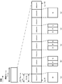
- slots are counted in ascending order from 0 to N ⁇ ⁇ subframe, ⁇ _ ⁇ slot ⁇ -1 in the subframe, and 0 to N ⁇ ⁇ frame, ⁇ _ ⁇ slot in the frame.
- ⁇ -1 are counted in ascending order.
- N ⁇ ⁇ slot ⁇ _ ⁇ symb ⁇ consecutive OFDM symbols in the slot based on the slot settings and the cyclic prefix.
- N ⁇ ⁇ slot ⁇ _ ⁇ symb ⁇ is 14.
- scheduling a slot may be expressed as scheduling a resource in which the relative time position between the reference signal and the slot boundary is fixed.
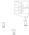
- FIG. 6 is a diagram showing an example of beamforming.
- a plurality of antenna elements are connected to one transmission unit (TXRU: Transceiver unit) 50, the phase is controlled by a phase shifter 51 for each antenna element, and the transmission from the antenna element 52 causes the transmission signal to move in any direction. You can aim the beam.
- TXRU may be defined as an antenna port, and in the terminal device 1, only the antenna port may be defined.
- directivity can be directed in an arbitrary direction, so that the base station device 3 can communicate with the terminal device 1 using a beam having a high gain.
- BWP switching for a serving cell is used to activate inactive (deactivated) BWPs and deactivate active (activated) BWPs. To be done. BWP switching for a certain serving cell is controlled by PDCCH indicating downlink allocation or uplink grant. BWP switching for a serving cell may also be controlled by the BWP inactivity timer, RRC signaling, or by the MAC entity itself at the start of the random access procedure. In addition of SpCell (PCell or PSCell) or activation of SCell, one BWP is first active without receiving PDCCH indicating downlink allocation or uplink grant.
- the MAC entity of the terminal device 1 applies the normal process. Normal processing includes transmitting UL-SCH, transmitting RACH, monitoring PDCCH, transmitting PUCCH, transmitting SRS, and receiving DL-SCH.
- the MAC entity of the terminal device 1 does not transmit the UL-SCH, does not transmit the RACH, does not monitor the PDCCH, does not transmit the PUCCH, Does not transmit SRS and does not receive DL-SCH. If a serving cell is deactivated, there may be no active BWPs (eg, active BWPs are deactivated).
- the BWP information element (IE) included in the RRC message (system information notified or information sent by the dedicated RRC message) is used to set the BWP.
- the RRC message transmitted from the base station device 3 is received by the terminal device 1.
- the network (such as the base station device 3) has at least one downlink BWP and one (if the serving cell is configured for uplink) or two (supplementary uplink). Is set), at least an initial BWP (initial BWP) including an uplink BWP (for example, is used) is set for the terminal device 1. Further, the network may configure additional uplink BWP or downlink BWP for a serving cell.
- the BWP setting is divided into an uplink parameter and a downlink parameter.
- the initial DL BWP may be indicated by the upper layer parameter initialDownlinkBWP.
- the upper layer parameter initialDownlinkBWP may be included in SIB1 (systemInformationBlockType1, ServingCellConfigCommonSIB) or ServingCellCongfigCommon.
- SIB1 systemInformationBlockType1, ServingCellConfigCommonSIB
- ServingCellCongfigCommon ServingCellCongfigure SIB is used to set the cell-specific parameter of the serving cell for the terminal device 1 in the SIB1.
- a (additional) DL BWP refers to (refers, acquires, etc.) the setting information of the CORESET of another BWP, the CORESET (or the bandwidth of the BWP) and / or the BWP is included in the frequency domain ( It may be necessary to at least satisfy that the (related) SS block is included in the additional BWP and uses the same subcarrier spacing.
- the terminal device 1 monitors a set of PDCCH candidates in one or more CORESETs arranged in each active serving cell configured to monitor the PDCCH.
- the set of PDCCH candidates corresponds to one or more search space sets. Monitoring refers to decoding each PDCCH candidate depending on the monitored DCI format or formats.
- a set of PDCCH candidates monitored by the terminal device 1 is defined by a PDCCH search space set).
- One search space set is a common search space set or a UE-specific search space set. In the above, the search space set is called a search space, the common search space set is called a common search space, and the UE-specific search space set is called a UE-specific search space.
- the terminal device 1 monitors PDCCH candidates with one or more of the following search space sets.
- search space set In this search space set, the search space type indicated by PDCCH-Config, which is an upper layer parameter, is set by the UE-specific search space (SearchSpace). .. This search space is for monitoring DCI format of CRC scrambled with C-RNTI, CS-RNTI (s), or MCS-C-RNTI.
- the BWP instruction field (bandwidth part indicator field) is not set in the DCI format (scheduling DCI), or when the terminal device 1 does not support active BWP change via the DCI format, resource allocation is performed.
- the RB numbering (RB indexing) of (uplink resource allocation type 0 and type 1) is determined in the active BWP of the terminal device 1. That is, in this case, the UL BWP determined by the terminal device 1 may be an active BWP. That is, the UL BWP to which the resource assignment is applied may be an active BWP (active UL BWP).
- the size of the DCI format in USS (or the size of the frequency domain resource assignment field included in the DCI format) is derived by the initial BWP, but is applied to the active BWP. It may be used in the case.
- the DCI format may be DCI format 0_0 and / or DCI format 0_1.
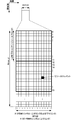
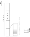
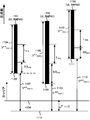
- FIG. 10 is a diagram showing an example for explaining the uplink resource allocation type 1 for BWP.
- the upper layer parameter OffsetToCarrier is an offset in the frequency domain between the point A and the lowest usable subcarrier of the carrier.
- the offset (1115) indicates the number of resource blocks in the subcarrier interval setting ⁇ . That is, when the subcarrier interval setting ⁇ is different, the band of the frequency region of the offset is different.
- 1104 may be the position of the resource block where the carrier starts.
- the physical resource blocks are resource blocks numbered in ascending order from 0 for each BWP.
- the start position (starting common resource block, N start BWP ) and the number of resource blocks (N size BWP ) are different for each BWP set in the terminal device 1.
- RB numbering of resource allocations starts with the lowest RB of the established UL BWP. For example, even if the calculated RB start value is the same, if the lowest RB of the determined UL BWP is different, the position of the common resource block to start is also different.
- the downlink control information may include a new data index (NDI: New Data Indicator).
- the new data indicator may be used to at least indicate whether the transport block corresponding to the new data indicator is an initial transmission.
- the new data index corresponds to a predetermined HARQ process number, corresponds to the transport block transmitted immediately before, the HARQ process number, and the PDSCH scheduled by the downlink control information including the new data index, and / or Alternatively, it may be information indicating whether the transport blocks included in the PUSCH are the same.
- the HARQ process number is a number used to identify the HARQ process.
- the HARQ process number may be included in the downlink control information.
- the HARQ process is a process for managing HARQ.
- the DCI format for the uplink (for example, DCI format 0_0) is used for releasing the semi-persistent schedule
- information on the HARQ process number included in the DCI format for the uplink (HARQ process number) fields are all set to '0'
- redundancy version information (Redundancy version) fields are set to '00'
- MCS and coding scheme information (Modulation and and coding scheme) fields are all ' It may be set to 1'and all fields of the information on frequency domain resource allocation (Frequency domain resource assignment) may be set to '1'.
- PUSCH transmission with the set grant is also referred to as PUSCH transmission corresponding to the set grant.
- the PUSCH transmission corresponding to the set grant may include a type 1 PUSCH transmission with the set grant (configured grant) and / or a type 2 PUSCH transmission with the set grant (configured grant).
- the PUSCH transmission scheduled by the DCI format in which the CRC scrambled by the CS-RNTI is added and the NDI (new data indicator) field is set to '0' is the DCI indicating the activation of the semi-persistent scheduling.
- PUSCH transmissions scheduled by the format may be supported.
- a PUSCH transmission scheduled by the DCI format in which the CRC scrambled by CS-RNTI is added and the NDI (new data indicator) field is set to '0' is the PUSCH transmission corresponding to the set grant. It may be.
- the PUSCH transmission corresponding to the set grant is the initial transmission of the PUSCH with the set grant.
- a PUSCH transmission scheduled with a DCI format in which a CRC scrambled by CS-RNTI is added and an NDI (new data indicator) field is set to "1" is a PUSCH transmission with a set grant. May be retransmitted.
- parameters applied to the PUSCH transmission are parameters included in configuredGrantConfig. And dataScramblingIdentityPUSCH, txConfig, codebookSubset, maxRank, scaling of UCI-OnPUSCH included in push-config.
- the PUSCH transmission with the set grant and the PUSCH transmission scheduled by the DCI format indicating the activation of semi-persistent scheduling may be referred to as the PUSCH transmission corresponding to the set grant. That is, the terminal device 1 may apply the PUSCH transmission by using the parameters shown in the configuredGrantConfig for the parameters required for the PUSCH transmission.
- the terminal device 1 may apply the PUSCH transmission using the parameters provided by configuredGrantConfig.
- the terminal device 1 may apply the PUSCH transmission using the parameters provided by the push-config when the parameters are not provided by the configuredGrantConfig.
- the parameters dataScramblingIdentityPUSCH, txConfig, codebookSubset, maxRank, scaling of UCI-OnPUSCH not provided by configuredGrantConfig may be provided by push-config. scaling of UCI-OnPUSCH is a parameter that indicates the scaling factor that limits the number of resource elements allocated to UCI on PUSCH.
- RepK Used to indicate the number of repeated PUSCH transmissions.
- RepK-RV Used to indicate information about the redundancy version of repeated PUSCH transmission.
- -Periodicity used to indicate the period of PUSCH transmission corresponding to the set grant.
- -Rrc-ConfiguredUplinkGrant Type 1 Used to indicate the information of the grant to be set.
- Setting resourceAllocation to'dynamicSwitch ' may mean that both resource allocation type 0 and resource allocation type 1 are set.
- the base station apparatus 3 may indicate either resource allocation type 0 or resource allocation type 1 by using 1 bit in the frequency domain resource allocation field. Good. For example, if the bit is set to 0, resource allocation type 0 may be indicated. Also, for example, if the bit is set to 1, resource allocation type 1 may be indicated.
- Setting resourceAllocation to'resourceAllocationType0 ' may mean that resource allocation type 0 is set.
- Setting resourceAllocation to'resourceAllocationType1 ' may mean that resource allocation type 1 is set.
- the terminal device 1 may determine the size of the'Frequency hopping flag 'field included in the DCI format 0_1 as 0 bit. That is, when frequencyHopping is set for either the upper layer parameter push-config or the upper layer parameter configuredGrantConfig, the terminal device 1 sets the size of the'Frequency hopping flag 'field included in the DCI format 0_1 to 1 It may be determined as a bit.
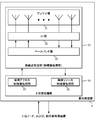
- the upper layer processing unit 14 outputs the uplink data (which may be referred to as a transport block) generated by a user operation or the like to the wireless transmission / reception unit 10.
- the upper layer processing unit 14 is a medium access control (MAC: Medium Access Control) layer, a packet data integration protocol (Packet Data Convergence Protocol: PDCP) layer, a radio link control (Radio Link Control: RLC) layer, a radio resource control (Radio). Resource Control: RRC) Performs part or all of the layer.
- the upper layer processing unit 14 may have a function of selecting one reference signal from one or a plurality of reference signals based on the measurement value of each reference signal.
- the upper layer processing unit 14 may have a function of selecting a PRACH opportunity associated with one selected reference signal from one or a plurality of PRACH opportunities.
- the upper layer processing unit 14 sets 1 set in the upper layer (for example, the RRC layer) when the bit information included in the information instructing the start of the random access procedure received by the wireless transmission / reception unit 10 has a predetermined value. It may have a function of specifying one index from one or a plurality of indexes and setting it as a preamble index.
- the upper layer processing unit 14 may have a function of identifying an index associated with the selected reference signal from among one or more indexes set by RRC and setting it as a preamble index.
- the baseband unit 13 converts the analog signal input from the RF unit 12 into an analog signal into a digital signal.
- the baseband unit 13 removes a portion corresponding to CP (Cyclic Prefix) from the converted digital signal, performs a fast Fourier transform (FFT) on the signal from which CP is removed, and outputs a signal in the frequency domain. Extract.
- CP Cyclic Prefix
- FFT fast Fourier transform
- the RF unit 12 removes extra frequency components from the analog signal input from the baseband unit 13 by using a low-pass filter, up-converts the analog signal into a carrier frequency, and transmits it via the antenna unit 11. To do. Further, the RF unit 12 amplifies the power. Further, the RF unit 12 may have a function of determining the transmission power of the uplink signal and / or the uplink channel transmitted in the serving cell.
- the RF unit 12 is also referred to as a transmission power control unit.
- Each of the units 10 to 16 provided in the terminal device 1 may be configured as a circuit.
- Each of the units denoted by reference numerals 30 to 36 included in the base station device 3 may be configured as a circuit.
- the parameter applied to the third parameter has a third parameter and a fourth parameter,
- the parameter is provided by the first parameter
- the fourth parameter is provided by the second parameter
- the first parameter includes at least transformPrecoder and resourceAllocation
- the fourth parameter is , At least transformPrecoder, and resourceAllocation
- the third parameter includes at least dataScramblingIdentityPUSCH
- the transformPrecoder indicates the transform precoding information for the first PUSCH transmission
- the resourceAllocation the 1 shows the resource allocation type of PUSCH transmission
- the dataScramblingIdentityPUSCH is an identifier used for initialization of the data scrambling of the first PUSCH.
Landscapes
- Engineering & Computer Science (AREA)
- Computer Networks & Wireless Communication (AREA)
- Signal Processing (AREA)
- Mobile Radio Communication Systems (AREA)
Abstract
L'invention concerne un dispositif terminal et un dispositif de station de base qui réalisent efficacement des communications. Le dispositif terminal transmet un premier PUSCH programmé selon un format DCI 0_1 avec un CS-RNTI, règle un paramètre PUSCH spécifique à un UE pour un premier paramètre, et règle la transmission PUSCH correspondant à une autorisation établie pour un second paramètre ; lorsque le NDI inclus dans le format DCI 0_1 est fixé à 1, des paramètres appliqués à la première transmission PUSCH présentent un troisième paramètre et un quatrième paramètre, le troisième paramètre est fourni par le premier paramètre, le quatrième paramètre est fourni par le deuxième paramètre, le premier paramètre comprend au moins un précodeur de transformation, et le quatrième paramètre comprend au moins un précodeur de transformation.
Applications Claiming Priority (2)
| Application Number | Priority Date | Filing Date | Title |
|---|---|---|---|
| JP2018206551A JP2020072421A (ja) | 2018-11-01 | 2018-11-01 | 基地局装置、端末装置、通信方法、および、集積回路 |
| JP2018-206551 | 2018-11-01 |
Publications (1)
| Publication Number | Publication Date |
|---|---|
| WO2020091046A1 true WO2020091046A1 (fr) | 2020-05-07 |
Family
ID=70461914
Family Applications (1)
| Application Number | Title | Priority Date | Filing Date |
|---|---|---|---|
| PCT/JP2019/043043 Ceased WO2020091046A1 (fr) | 2018-11-01 | 2019-11-01 | Dispositif de station de base, dispositif terminal, et procédé de communication |
Country Status (2)
| Country | Link |
|---|---|
| JP (1) | JP2020072421A (fr) |
| WO (1) | WO2020091046A1 (fr) |
Cited By (1)
| Publication number | Priority date | Publication date | Assignee | Title |
|---|---|---|---|---|
| US20230045623A1 (en) * | 2021-08-03 | 2023-02-09 | Qualcomm Incorporated | Uplink power control with fallback downlink control information |
Families Citing this family (3)
| Publication number | Priority date | Publication date | Assignee | Title |
|---|---|---|---|---|
| CN120730455A (zh) * | 2020-08-07 | 2025-09-30 | 中兴通讯股份有限公司 | 无线通信方法、无线通信装置、存储介质 |
| WO2022080983A1 (fr) * | 2020-10-16 | 2022-04-21 | 엘지전자 주식회사 | Embrouillage pour répétition pusch |
| JP2024020669A (ja) * | 2020-12-24 | 2024-02-15 | シャープ株式会社 | 端末装置、基地局装置、および、通信方法 |
-
2018
- 2018-11-01 JP JP2018206551A patent/JP2020072421A/ja active Pending
-
2019
- 2019-11-01 WO PCT/JP2019/043043 patent/WO2020091046A1/fr not_active Ceased
Non-Patent Citations (2)
| Title |
|---|
| NTT DOCOMO, INC.: "Discussion on remaining issues for UL data transmission procedure", 3GPP TSG RAN WG1 MEETING #94BIS RI-1812054, 12 October 2018 (2018-10-12), XP051519379 * |
| NTT DOCOMO, INC.: "R emaining issues for UL data transmission procedure", 3GPP TSG RAN WG1 MEETING #94BIS RI-1812018, 11 October 2018 (2018-10-11), XP051519341 * |
Cited By (2)
| Publication number | Priority date | Publication date | Assignee | Title |
|---|---|---|---|---|
| US20230045623A1 (en) * | 2021-08-03 | 2023-02-09 | Qualcomm Incorporated | Uplink power control with fallback downlink control information |
| US12200716B2 (en) * | 2021-08-03 | 2025-01-14 | Qualcomm Incorporated | Uplink power control with fallback downlink control information |
Also Published As
| Publication number | Publication date |
|---|---|
| JP2020072421A (ja) | 2020-05-07 |
Similar Documents
| Publication | Publication Date | Title |
|---|---|---|
| CN113366903B (zh) | 基站装置、终端装置以及通信方法 | |
| JP7246874B2 (ja) | 基地局装置、端末装置、および、通信方法 | |
| CN113475138B (zh) | 用户设备、基站装置及通信方法 | |
| CN113273284B (zh) | 基站装置、终端装置以及通信方法 | |
| US11778603B2 (en) | Base station apparatus, terminal apparatus, and communication method | |
| US20220369297A1 (en) | Terminal apparatus, base station apparatus, and communication method | |
| US11849449B2 (en) | Base station apparatus, terminal apparatus, communication method, and integrated circuit | |
| WO2020166625A1 (fr) | Procédé de communication, dispositif terminal, dispositif de station de base, et circuit intégré | |
| JP7390111B2 (ja) | 基地局装置、端末装置、および、通信方法 | |
| WO2020203427A1 (fr) | Dispositif de station de base, dispositif terminal et procédé de communication | |
| JP7390112B2 (ja) | 端末装置、および、通信方法 | |
| WO2020075775A1 (fr) | Dispositif de station de base, dispositif terminal, procédé de communication, et circuit intégré | |
| WO2020195531A1 (fr) | Dispositif de station de base, dispositif terminal et procédé de communication | |
| JP2022025801A (ja) | 端末装置、基地局装置、および、通信方法 | |
| JP2020072421A (ja) | 基地局装置、端末装置、通信方法、および、集積回路 | |
| JP7737994B2 (ja) | 端末装置、基地局装置、および、通信方法 | |
| JP7580954B2 (ja) | 端末装置、基地局装置、および、通信方法 | |
| JP7690453B2 (ja) | 端末装置、基地局装置、および、通信方法 | |
| JP7526008B2 (ja) | 端末装置、基地局装置、および、通信方法 | |
| JP7526009B2 (ja) | 端末装置、基地局装置、および、通信方法 |
Legal Events
| Date | Code | Title | Description |
|---|---|---|---|
| 121 | Ep: the epo has been informed by wipo that ep was designated in this application |
Ref document number: 19877723 Country of ref document: EP Kind code of ref document: A1 |
|
| NENP | Non-entry into the national phase |
Ref country code: DE |
|
| 122 | Ep: pct application non-entry in european phase |
Ref document number: 19877723 Country of ref document: EP Kind code of ref document: A1 |