WO2020093421A1 - Convoyeur à double chaîne vertical - Google Patents
Convoyeur à double chaîne vertical Download PDFInfo
- Publication number
- WO2020093421A1 WO2020093421A1 PCT/CN2018/115148 CN2018115148W WO2020093421A1 WO 2020093421 A1 WO2020093421 A1 WO 2020093421A1 CN 2018115148 W CN2018115148 W CN 2018115148W WO 2020093421 A1 WO2020093421 A1 WO 2020093421A1
- Authority
- WO
- WIPO (PCT)
- Prior art keywords
- tower
- chain
- sleeve
- fuel tank
- pin
- Prior art date
- Legal status (The legal status is an assumption and is not a legal conclusion. Google has not performed a legal analysis and makes no representation as to the accuracy of the status listed.)
- Ceased
Links
Images


Classifications
-
- B—PERFORMING OPERATIONS; TRANSPORTING
- B65—CONVEYING; PACKING; STORING; HANDLING THIN OR FILAMENTARY MATERIAL
- B65G—TRANSPORT OR STORAGE DEVICES, e.g. CONVEYORS FOR LOADING OR TIPPING, SHOP CONVEYOR SYSTEMS OR PNEUMATIC TUBE CONVEYORS
- B65G23/00—Driving gear for endless conveyors; Belt- or chain-tensioning arrangements
- B65G23/44—Belt or chain tensioning arrangements
-
- B—PERFORMING OPERATIONS; TRANSPORTING
- B65—CONVEYING; PACKING; STORING; HANDLING THIN OR FILAMENTARY MATERIAL
- B65G—TRANSPORT OR STORAGE DEVICES, e.g. CONVEYORS FOR LOADING OR TIPPING, SHOP CONVEYOR SYSTEMS OR PNEUMATIC TUBE CONVEYORS
- B65G45/00—Lubricating, cleaning, or clearing devices
- B65G45/02—Lubricating devices
- B65G45/08—Lubricating devices for chains
-
- B—PERFORMING OPERATIONS; TRANSPORTING
- B65—CONVEYING; PACKING; STORING; HANDLING THIN OR FILAMENTARY MATERIAL
- B65G—TRANSPORT OR STORAGE DEVICES, e.g. CONVEYORS FOR LOADING OR TIPPING, SHOP CONVEYOR SYSTEMS OR PNEUMATIC TUBE CONVEYORS
- B65G49/00—Conveying systems characterised by their application for specified purposes not otherwise provided for
- B65G49/02—Conveying systems characterised by their application for specified purposes not otherwise provided for for conveying workpieces through baths of liquid
- B65G49/04—Conveying systems characterised by their application for specified purposes not otherwise provided for for conveying workpieces through baths of liquid the workpieces being immersed and withdrawn by movement in a vertical direction
-
- B—PERFORMING OPERATIONS; TRANSPORTING
- B65—CONVEYING; PACKING; STORING; HANDLING THIN OR FILAMENTARY MATERIAL
- B65G—TRANSPORT OR STORAGE DEVICES, e.g. CONVEYORS FOR LOADING OR TIPPING, SHOP CONVEYOR SYSTEMS OR PNEUMATIC TUBE CONVEYORS
- B65G2207/00—Indexing codes relating to constructional details, configuration and additional features of a handling device, e.g. Conveyors
- B65G2207/08—Adjustable and/or adaptable to the article size
Definitions
- the invention relates to the technical field of automobile painting equipment, in particular to a vertical double-chain conveyor.
- the current domestic automobile production equipment is at least 10 years behind the international advanced level.
- the outstanding performance is in three aspects: first, the sustainable utilization rate of the equipment is low, and the life of imported equipment is more than 3 times the life of domestic equipment; second, the accuracy is poor, and the accuracy of imported equipment is often more than 10 times the accuracy of domestic equipment; third, intelligent
- the level is low, domestic automobile production equipment still needs a lot of manual operation, the product's intelligence and reliability are not high, and it covers a large area, consumes energy and causes serious pollution.
- the domestic automobile coating production line mainly uses a single-track trolley suspension conveyor.
- This structure is a type of electric hoist and accumulation-type suspension conveyor.
- the main functional components are: walking track, power transmission guide rail, turnout, rotating disc, elevator, running trolley , Spreader and control system.
- this transportation method can no longer meet the requirements of mass production, process level and quality on the automated transportation of heavy-duty wide bodies and large workpieces.
- the typical types are: 1
- the body of coaches has always been electrophoresed on the parts before body assembly, and then assembled.
- the invention provides a vertical double-chain conveyor, which is used to provide a conveyor that can meet the requirements of mass production, process level and quality on the overall automatic transportation of heavy-load wide bodies and large workpieces.
- the invention provides a vertical double-chain conveyor, including:
- the inward tower is a steel frame structure
- the outlet tower is provided corresponding to the inlet tower and has a frame structure, and an electric swimming pool is provided between the inlet tower and the outlet tower;
- Rolling bed system the rolling bed system is set on the return line from the outgoing tower to the incoming tower, and plays the role of returning the skid body;
- the chain track steel structure is provided with two parallel to each other, and its two ends are fixedly arranged on the inlet tower and the outlet tower respectively, including the lateral direction connecting the upper part of the inlet tower and the outlet tower A section, a first longitudinal section provided in the incoming piece tower and a second longitudinal section provided in the outgoing piece tower, the middle of the transverse section is sunk to immerse the workpiece in the electric swimming pool;
- the horizontal support rails are installed on the ground between the lower ends of the inlet and outlet towers;
- a chain rail, the chain rail and the steel structure of the chain rail are connected by a boom, and the chain rail is provided with a conveyor chain, and the conveyor chain travels inside the chain rail;
- a driving device is provided at the upper end of the outlet tower, and is used to drive the chain track to run;
- Hanging spreaders are provided with several groups. Each group of hanging spreaders includes two hanging rods, which are spaced by a station length between the two hanging rods. Two of the conveyor chains.
- the lateral section includes two upper rails and one lower rail, the lower rails are disposed between the two upper rails, and are connected by an inclined rail and the connection is smoothly transitioned, and the inclined angle of the inclined rail It is 40 degrees to 50 degrees, and the middle of the lower rail is provided with an upwardly protruding swing section.
- the suspension bar is a door-shaped pocket bottom structure, the upper part is wider and the lower part is narrow, and the wide and narrow part is an arc transition; the top of the suspension bar is hung on the conveyor chain through a self-aligning bearing, and the conveyor chain has two There are wheels running on the side of the chain track, and a nylon roller is fixed at the middle of the bottom of each suspension rod, and the nylon roller slides on the horizontal support rail.
- the conveying chain is tensioned downward by a weight tensioning device
- the weight tensioning device includes two independent curved rails, a counterweight box and a guide wheel, each of the curved rails is installed on the weight
- the counterweight box of the tensioning device is vertically lifted along with the counterweight guide rail together with the counterweight box.
- the weight tensioning device is provided with a lowering guide plate and a returning guide plate, and the lowering guide plate is fixed at On the counterweight box, the return guide plate is fixedly connected to a suspension rod below the counterweight box, and the suspension rod is sheathed on the outside of the vertical section of the fixed guide plate by a cross bar and fixed with bolts.
- a self-lubricating device including a refueling mechanism and a control mechanism.
- the refueling mechanism includes a frame, an oil tank, a connecting pipe, and a fuel tank.
- the oil tank is fixed on the frame.
- the lower end of the oil tank is connected to the The connecting pipe.
- the lower end of the connecting pipe is connected to the fuel tank, an oil outlet is opened on the bottom surface of the fuel tank, a nozzle is connected to the oil outlet, and the nozzle is located above the chain.
- the fuel tank includes a fuel tank body, a fuel tank cap, an air filter, a liquid level gauge and an oil leakage port, the fuel tank cap is fixed on the top surface of the fuel tank body, and the liquid level gauge and the oil leakage port are provided on the On the side wall of the fuel tank body, the air filter is provided on the fuel tank cap, the oil leakage port is connected to the connection pipe, and the control mechanism includes a housing, a control board, an electromagnet, a switch, and a support rod,
- the housing is connected to the side wall of the connection tube, one end of the control board passes through the side wall of the connection tube and is located in the connection tube, and the control board and the side wall of the connection tube are connected There is a spring, the other end of the control board An iron surface layer is connected, the control board is located on one side of the electromagnet, both ends of the electromagnet are connected to the switch through a circuit, and one end of the support rod is hinged to the connecting piece of the switch A piston is connected to the other end of
- the skid includes a fixing bracket and a locking support device.
- the fixing bracket includes a base and a first support frame, a second support frame, and a third support frame provided on the base; the first Two support frames are installed between the first support frame and the third support frame, and the positions of the first support frame, the second support frame, and the third support frame on the base may be Adjustment
- the locking support device includes a locking pin, a bracket, a fixing plate, a pin shaft, two spring plates, a dial plate and a pin; the locking pin is co-pinned by the pin
- the shaft is fixed, the head of the lock pin is eccentric, and the body will be locked after rotation to achieve the purpose of locking the body;
- the bracket includes an eccentric sleeve; the pin and the eccentric sleeve are coaxial with each other , The pin shaft rotates inside the eccentric sleeve; the fixing plate fixes the eccentric sleeve and the two spring plates; by turning the dial plate, the lock pin is rotated; the pin shaft is Two
- the first support frame includes a first beam and a first sleeve, the first beam is provided on the top of the first sleeve, the first beam is provided with a positioning pin; the base There are first struts at different positions matching the first sleeve, the outer diameters of the first struts are smaller than the inner diameters of the first sleeve, and the first beam is also provided with a longitudinal section L-shaped front support column, the top of the front support column is provided with a first U-shaped flange, one end of the front support column is inserted into the first beam, and the second support frame includes a second beam and a Two sleeves, the second beam is arranged on the top of the second sleeve, and both ends of the second beam are connected with a middle support column with an L-shaped longitudinal section, and the top of the middle support column is provided with Inverted U-shaped flanging; the base is provided with a second pillar at a different position to match the second sleeve
- the head of the lock pin will lock the body after rotating 180 degrees to achieve the purpose of locking the body.
- the rotation of the pin shaft is achieved by the rotation of the dial under the support, the dial There are four clamping slots, which can be turned by the fixed rod beside the roller bed by the conveying speed of the skid.
- the dial is rotated 90 degrees every time it is turned, and it needs to be turned twice every time it is locked.
- Eccentric locking there is a notch on the dial, used to determine whether the locking support is in a locked state, the locking pin and the pin shaft are connected by the pin, the pin diameter is 6mm, so
- the pin shaft is limited by the spring plate, and the shaft is guided by the spring plate when the shaft rotates.
- the thickness of the spring plate is 2 mm and the material is 65Mn.
- the invention provides a vertical double-chain conveyor, which can meet the requirements of mass production, process level and quality on the overall automatic transportation of heavy-load wide bodies and large workpieces, and has high working efficiency.
- FIG. 1 is a schematic structural diagram of a vertical double-chain conveyor in an embodiment of the present invention
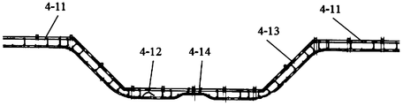
- FIG. 2 is a schematic diagram of the structure of the horizontal section in an embodiment of the present invention.
- FIG. 3 is a schematic view of the structure of a suspension rod in an embodiment of the present invention.
- FIG. 4 is a schematic structural diagram of a weight tensioning device in an embodiment of the present invention.
- FIG. 5 is a schematic structural diagram of a self-lubricating device in an embodiment of the present invention.
- FIG. 6 is a schematic structural view of an oil tank in an embodiment of the present invention.
- FIG. 7 is a schematic structural view of a fixed bracket in an embodiment of the present invention.
- FIG. 8 is a schematic structural diagram of a first support frame in an embodiment of the present invention.
- FIG. 9 is a schematic structural diagram of a second support frame in an embodiment of the present invention.
- FIG. 10 is a schematic structural diagram of a third support frame in an embodiment of the present invention.
- FIG. 11 is a schematic structural diagram of a locking and supporting device according to an embodiment of the present invention.
- an embodiment of the present invention provides a vertical double-chain conveyor, including:
- the inward tower is a steel frame structure
- the outlet tower 2 is provided corresponding to the inlet tower 1 and has a frame structure, and an electric swimming pool is provided between the inlet tower 1 and the outlet tower 2;
- Rolling bed system 3 the rolling bed system is arranged on the return line from the outgoing tower to the incoming tower, and plays the role of returning the skid body;
- the chain rail steel structure 4 is provided with two parallel to each other, and its two ends are respectively fixedly arranged on the inlet tower 1 and the outlet tower 2, including connecting the inlet tower 1 and the outlet
- Two horizontal support rails 5 are provided, which are parallel to each other.
- the horizontal support rails 5 are located on the ground and are located between the lower ends of the inlet tower 1 and the outlet tower 2;
- a chain rail 6, the chain rail 6 and the chain rail steel structure 4 are connected by a boom 7, the chain rail 6 is provided with a conveyor chain, and the conveyor chain travels inside the chain rail 6;
- Hanging spreaders are provided with several groups. Each group of hanging spreaders includes two suspension rods 8, and a space between the two suspension rods 8 is a station length.
- the suspension rod 8 is a door-shaped pocket bottom structure. The ends are suspended on the two said conveyor chains.
- the workpiece When in use, the workpiece is first transported to the transition point of the incoming tower through the skid. At this time, a group of hanging spreaders that follow the movement of the conveyor chain lift the skid from below, so that the skid follows the movement of the hanging spreader and enters the lateral direction When it reaches the sinking position in the middle of the horizontal section, it enters the electric swimming pool for electrophoresis, and then follows the conveyor chain to enter the outlet tower and enter the transfer position. The skid and workpiece are transported out by the roller bed system, and the hanging spreader continues to follow the chain track Enter the second longitudinal section, and then continue to move into the horizontal support track. After entering the first longitudinal section, start the next cycle.
- the vertical double-chain conveyor can meet the requirements of mass production, process level and quality on the overall automatic transportation of heavy-duty wide bodies and large workpieces, and has high working efficiency.
- the transverse section 4-1 includes two upper rails 4-11 and one lower rail 4-12, the lower rail 4-12 is disposed between the two upper rails 4-11, and is inclined rails 4-13 Connected and a smooth transition at the connection, the inclined angle of the inclined rail 4-13 is 45 degrees, and a swinging section 4-14 protruding upward is provided in the middle of the lower rail 4-12.
- the inclined track is inclined at a 45-degree angle, which makes the angle of the workpieces into and out of the electric swimming pool large, which can shorten the length of the production line, reduce the floor space, reduce the liquid carried by the workpiece, improve the utilization of chemical reagents and paint, and reduce pollution.
- the setting of the swing section makes the workpiece move in a small amplitude in the electric swimming pool, which is beneficial to reduce air bubbles and improve the quality of electrophoresis.
- the suspension bar 8 is a door-shaped pocket bottom structure, the upper part is wider and the lower part is narrow, and the wide and narrow part is a circular arc transition; the top of the suspension bar 8 is hung on the conveyor chain through the self-aligning bearing 9, and the conveyor chain has two There are wheels 10 running on the side of the chain track 6, a nylon roller 11 is fixed at the middle of the bottom of each suspension rod 8, and the nylon roller 11 slides on the horizontal support rail 5.
- the door type pocket bottom structure with a wider upper part and a narrower lower part can avoid collision or interference of the front and rear suspension rods.
- the nylon at the middle of the bottom end The rollers slide on the horizontal support rail, which is conducive to the movement of the suspension rod in the horizontal state and effectively avoids the wear of the suspension rod.
- the conveyor chain is tensioned downwards by the weight tensioning device 12, the weight tensioning device 12 includes two independent curved rails 13, a counterweight box 14 and guide wheels 15, each of the curved rails 13 is installed in the
- the weight box 14 of the weight tensioning device 12 is vertically lifted along with the weight guide rail 16 together with the weight box 14.
- the weight tensioning device 12 is provided with a lowering guide plate 17 and a return guide Plate 18, the lowering guide plate 17 is fixed on the counterweight box 14, the return guide plate 18 is fixedly connected to the hanger 19 under the counterweight box 14, the hanger 19 is sleeved on the crossbar 20
- the outside of the vertical section of the guide plate 21 is fixed and fixed with bolts.
- the tensioning device includes two independent curvilinear tracks, a counterweight box, and a guide wheel.
- Each curved track bent from channel steel is installed in the counterweight box and the counterweight guide rail.
- the counterweight box is along the counterweight guide rail Vertical lift
- the tensioning device is provided with a lowering guide plate and a return guide plate, which can effectively prevent the front and rear suspension rods from interfering with each other when the suspension rod is lowered
- the lowering guide plate is fixed on the counterweight box
- the return guide plate is fixedly connected below the counterweight box
- the suspension rod is fixed on the outside of the vertical section of the fixed guide plate by bolts.
- the lower guide plate and the return guide plate can move up and down along the counterweight guide rail with the counterweight box; fixed at the exit end of the chain track
- the guide plate is first arched upward, and then bent down, and the guide plate is fixed in the middle of the chain track in a horizontal state.
- the purpose is to cooperate with the track to make the suspension rod returned to the entrance end transition from the vertical state to the horizontal state.
- the chain track is tensioned downwards by means of a heavy hammer tensioner to compensate for the slack in the chain track due to wear.
- the refueling mechanism includes a frame 22, an oil tank 23, a connecting pipe 24, and a fuel tank 25.
- the oil tank 23 is fixed on the frame 22 and the oil tank 23
- the lower end of the connecting pipe 24 is connected to the lower end of the connecting pipe 24 is connected to the fuel tank 25, the bottom surface of the fuel tank 25 is opened with an oil outlet 26, the oil outlet 27 is connected to the nozzle 28 ,
- the nozzle 28 is located above the chain
- the fuel tank 23 includes a fuel tank body 23-1, a fuel tank cap 23-2, an air filter 23-3, a liquid level gauge 23-4 and an oil leak 23-5
- the The fuel tank cap 23-2 is fixed on the top surface of the fuel tank body 23-1
- the liquid level gauge 23-4 and the oil leakage port 23-5 are provided on the side wall of the fuel tank body 23-1
- the air filter 23-3 is provided on the fuel tank cap 23-2
- the oil leakage port 23-5 is connected to the connecting pipe 24, and the control
- the lubricating oil flows out of the nozzle after flowing through the oil outlet, and lubricates the chain under the nozzle.
- the lubricating oil in the fuel tank gradually decreases, the liquid level drops, the piston drops with the liquid level, the support rod drops, and the hinged connection piece of the bracket is pulled down.
- the switch is closed, the circuit is connected, and the electromagnetic The iron starts to attract the control board on one side.
- the control board moves under the action of the electromagnet, so that the connecting pipe is in a connected state.
- the lubricating oil in the oil tank flows into the fuel tank through the connected connecting pipe.
- the rise and fall of the control circuit is opened and closed, thus completing the replenishment operation of the lubricating oil in the fuel tank, ensuring that the lubricating oil is always stored in the fuel tank, ensuring the continuous operation of the lubricating operation, the operation is simple, and because the volume of the fuel tank is relatively small Large, so that one replenishment of the fuel tank can ensure long-term lubrication operation, simplifying frequent replenishment operations; after setting the filter, it is ensured that there is no impurities in the lubricating oil flowing into the fueling nozzle, thereby ensuring a better lubrication effect; By providing a polished layer on the surface of the support rod, the wear of the support rod during sliding is reduced, and the service life of the support rod is prolonged; after the seal pad is provided, the sealing of the joint is ensured, and leakage is avoided. It leads to waste phenomenon; after the bearing is installed at the hinge, the wear of the support rod and the connecting piece when moving is reduced.
- the lubrication device provided above the chain is used, and the piston is used to rise and fall with the rise of the lubricating oil level to open and close the control circuit, thereby completing the replenishment operation of lubricating oil in the fuel tank Ensure that there is always lubricating oil in the fuel tank, ensure the continuous operation of the lubrication operation, and the operation is simple, and because the volume of the fuel tank is large, one replenishment of the fuel tank can ensure long-term lubrication operation, simplifying frequent replenishment operations .
- the skid includes a fixed bracket and a locking support device.
- the fixed bracket includes a base 37 and a first support frame 38, a second support frame 39, and a third support frame 40 provided on the base 37;
- the second support frame 39 is disposed between the first support frame 38 and the third support frame 40.
- the first support frame 38, the second support frame 39, and the third support frame 40 are The position on the base 37 can be adjusted.
- the locking support device includes a locking pin 41, a bracket 42, a fixing plate 43, a pin shaft 44, two spring plates 45, a dial 46 and A pin 47; the lock pin 44 is fixed to the pin shaft by the pin 47, the head of the lock pin 44 is eccentric, and will lock the body after rotation to achieve the purpose of locking the body;
- the bracket 42 includes an eccentric sleeve 48; the pin 44 and the eccentric sleeve 48 are coaxial with each other, the pin 44 rotates within the eccentric sleeve 48; the fixing plate 43 fixes the eccentric sleeve 48 And the two spring plates 45; by turning the dial plate 46, the lock pin 41 is rotated; the pin 44 is clamped by the two spring plates 45
- the pin 44 is chamfered, when the position of the pin 44 to the chamfer, will be affected by the spring force of the spring plate 45 and back to the original position.
- the first support frame 38 includes a first beam 48 and a first sleeve 49.
- the first beam 48 is provided on the top of the first sleeve 49.
- the first beam 48 is provided with a positioning pin 50;
- the base 37 is provided with first pillars 50 at different positions matching the first sleeve 49.
- the outer diameter of the first pillar 50 is smaller than the inner diameter of the first sleeve 49.
- a cross beam 48 is further provided with a front support column 51 with an L-shaped longitudinal section.
- the top of the front support column 51 is provided with a first U-shaped flange 52.
- the second support frame 39 includes a second beam 52 and a second sleeve 53, the second beam 52 is disposed on the top of the second sleeve 53, and both ends of the second beam 52 are inserted
- a middle support post 54 with an L-shaped longitudinal section is connected, and an inverted U-shaped flange 55 is provided on the top of the middle support post 54;
- the base 37 is provided with different positions matching the second sleeve 53
- the second post 56 has an outer diameter smaller than the inner diameter of the second sleeve 53
- the third support frame 40 includes a third beam 57 and a third sleeve 58, the third Beam 57 is located at the Institute On the top of the third sleeve 58, a second U-shaped flange 59 is provided on the third beam 57; a third pillar with a different position matching the third sleeve 58 is provided on the base 37 60.
- the outer diameter of the third pillar 60 is smaller than the inner diameter of the third sleeve 58.
- the base 37 includes a connecting plate 61 and parallel first and second longitudinal beams 62 and 63.
- the connecting plate 61 has a chevron cross section, and both sides of the connecting plate 61 are fixed to the tops of the first longitudinal beam 62 and the second longitudinal beam 63.
- the head of the lock pin 41 will lock the body after rotating 180 degrees to achieve the purpose of locking the body.
- the rotation of the pin shaft 44 is achieved by the rotation of the dial 46 under support, the dial 46 There are four slots on the board, and the speed of the skid is used to toggle through the fixed rod next to the roller bed.
- the dial 46 rotates 90 degrees every time it is turned, and needs to be turned twice for each locking, forming a rotation of 180 Degree of eccentric locking, there is a notch on the dial 46, used to determine whether the locking support is in a locked state, the locking pin 41 and the pin shaft 44 are connected by the pin 47, the pin The diameter of the sub 47 is 6 mm.
- the pin shaft 44 is limited by the spring plate 45. When the shaft rotates, it is guided by the spring plate 45.
- the thickness of the spring plate 45 is 2 mm and the material is 65Mn.
- This embodiment includes a base and a first support frame, a second support frame and a third support frame provided on the base, the second support frame is provided on the first support frame and the third support frame
- the positions of the first support frame, the second support frame, and the third support frame on the base can be adjusted; in this embodiment, the first support frame and the second support frame can be adjusted
- the third support frame can meet the needs of different vehicle models.
- this embodiment can be used for painting production of various types of vehicles, which has high versatility and saves costs.
- the locking and supporting device of this embodiment has a compact structure and a reasonable design, can be connected and fixed with the swing rod, and lock the vehicle body at the same time, and has the characteristics of light locking, easy to accumulate paint, and easy cleaning.
Landscapes
- Engineering & Computer Science (AREA)
- Mechanical Engineering (AREA)
- Chain Conveyers (AREA)
Abstract
L'invention concerne un convoyeur à double chaîne vertical, comprenant : une tour d'alimentation de pièces (1) et une tour d'évacuation de pièces (2) arrangée en correspondance avec la tour d'alimentation de pièces (1), un groupe électrique étant disposé entre la tour d'alimentation de pièces (1) et la tour d'évacuation de pièces (2) ; un système de lit à rouleaux (3) disposé sur la ligne de retour de la tour d'évacuation de pièces (2) à la tour d'alimentation de pièces (1) ; une structure en acier de rail à chaîne (4) dont les deux extrémités sont respectivement fixées à la tour d'alimentation de pièces (1) et à la tour d'évacuation de pièces (2) ; un rail support horizontal (5) positionné entre la tour d'alimentation de pièces (1) et l'extrémité inférieure de la tour d'évacuation de pièces (2) ; des chaînes de convoyeur disposées dans un rail à chaîne (6), le rail à chaîne (6) étant relié de manière fixe à la structure en acier de rail à chaîne (4) ; un appareil d'entraînement (7) disposé à l'extrémité supérieure de la tour d'évacuation de pièces (2) et utilisé pour entraîner les chaînes de convoyeur à se déplacer, chaque jeu de suspentes comprenant deux tiges de suspension (8) et les deux extrémités des tiges de suspension (8) étant suspendues sur deux chaînes de convoyeur. La présente solution peut satisfaire aux exigences de production par lots, de niveau technique et de qualité pour le convoyage entièrement automatique de larges corps à charge lourde et de grandes pièces ouvrées, et présente un rendement de travail élevé.
Applications Claiming Priority (2)
| Application Number | Priority Date | Filing Date | Title |
|---|---|---|---|
| CN201811312323.9 | 2018-11-06 | ||
| CN201811312323.9A CN109484802A (zh) | 2018-11-06 | 2018-11-06 | 垂直双链输送机 |
Publications (1)
| Publication Number | Publication Date |
|---|---|
| WO2020093421A1 true WO2020093421A1 (fr) | 2020-05-14 |
Family
ID=65693883
Family Applications (1)
| Application Number | Title | Priority Date | Filing Date |
|---|---|---|---|
| PCT/CN2018/115148 Ceased WO2020093421A1 (fr) | 2018-11-06 | 2018-11-13 | Convoyeur à double chaîne vertical |
Country Status (2)
| Country | Link |
|---|---|
| CN (1) | CN109484802A (fr) |
| WO (1) | WO2020093421A1 (fr) |
Families Citing this family (3)
| Publication number | Priority date | Publication date | Assignee | Title |
|---|---|---|---|---|
| CN109911523B (zh) * | 2019-04-03 | 2024-04-02 | 合肥三益江海智能科技有限公司 | 一种悬挂链输送系统中紧急自动离合装置 |
| CN110670059B (zh) * | 2019-10-10 | 2020-07-17 | 浙江冠林机械有限公司 | 一种电动葫芦自动化加工生产线 |
| CN113955497A (zh) * | 2021-11-12 | 2022-01-21 | 承德环宇输送机械制造有限公司 | 输送装置及镀锌生产线 |
Citations (6)
| Publication number | Priority date | Publication date | Assignee | Title |
|---|---|---|---|---|
| CN101898687A (zh) * | 2010-08-13 | 2010-12-01 | 中国汽车工业工程公司 | 用于汽车涂装车间的u形摆杆输送机 |
| CN102083719A (zh) * | 2008-02-21 | 2011-06-01 | 艾森曼设备制造有限及两合公司 | 悬挂轨道系统和带有这种系统的浸渍处理设备 |
| CN105314401A (zh) * | 2015-11-02 | 2016-02-10 | 天奇自动化工程股份有限公司 | 自动翻转浸液设备 |
| CN105318174A (zh) * | 2015-12-09 | 2016-02-10 | 重庆蜂糖妹农业开发有限公司 | 链条的润滑装置 |
| US20160237588A1 (en) * | 2011-06-30 | 2016-08-18 | Almex Pe Inc. | Surface treatment system and workpiece-holding jig |
| CN207308165U (zh) * | 2017-07-28 | 2018-05-04 | 安徽江淮汽车集团股份有限公司 | 一种汽车通用涂装滑橇 |
Family Cites Families (4)
| Publication number | Priority date | Publication date | Assignee | Title |
|---|---|---|---|---|
| CN102431769B (zh) * | 2011-10-31 | 2014-12-24 | 中汽昌兴(洛阳)机电设备工程有限公司 | 一种烘干双链输送机 |
| CN102965712B (zh) * | 2012-12-12 | 2014-11-26 | 安徽江淮汽车股份有限公司 | 一种适用于汽车涂装摆杆输送系统的电泳滑橇 |
| NL2014241B1 (en) * | 2015-02-05 | 2016-10-12 | Rexnord Flattop Europe Bv | Modular conveyor. |
| CN105351713B (zh) * | 2015-12-09 | 2017-10-31 | 重庆蜂糖妹农业开发有限公司 | 运输线的自动润滑装置 |
-
2018
- 2018-11-06 CN CN201811312323.9A patent/CN109484802A/zh active Pending
- 2018-11-13 WO PCT/CN2018/115148 patent/WO2020093421A1/fr not_active Ceased
Patent Citations (6)
| Publication number | Priority date | Publication date | Assignee | Title |
|---|---|---|---|---|
| CN102083719A (zh) * | 2008-02-21 | 2011-06-01 | 艾森曼设备制造有限及两合公司 | 悬挂轨道系统和带有这种系统的浸渍处理设备 |
| CN101898687A (zh) * | 2010-08-13 | 2010-12-01 | 中国汽车工业工程公司 | 用于汽车涂装车间的u形摆杆输送机 |
| US20160237588A1 (en) * | 2011-06-30 | 2016-08-18 | Almex Pe Inc. | Surface treatment system and workpiece-holding jig |
| CN105314401A (zh) * | 2015-11-02 | 2016-02-10 | 天奇自动化工程股份有限公司 | 自动翻转浸液设备 |
| CN105318174A (zh) * | 2015-12-09 | 2016-02-10 | 重庆蜂糖妹农业开发有限公司 | 链条的润滑装置 |
| CN207308165U (zh) * | 2017-07-28 | 2018-05-04 | 安徽江淮汽车集团股份有限公司 | 一种汽车通用涂装滑橇 |
Also Published As
| Publication number | Publication date |
|---|---|
| CN109484802A (zh) | 2019-03-19 |
Similar Documents
| Publication | Publication Date | Title |
|---|---|---|
| WO2020093421A1 (fr) | Convoyeur à double chaîne vertical | |
| CN106345825A (zh) | 一种具有升降和双向移钢功能的链式移钢机 | |
| CN206107398U (zh) | 一种报废汽车拆解线 | |
| CN109719067B (zh) | 曲轴组合式最终清洗设备 | |
| CN204310782U (zh) | 炉体或槽体沉没辊道安装装置 | |
| CN107552278A (zh) | 一种抗硫抗氢弯管管件材料的材质色标喷涂装置 | |
| CN115256136B (zh) | 一种衬砌台车模板自动化打磨设备及其使用方法 | |
| CN110834955A (zh) | 一种汽车涂装前处理电泳输送设备及输送方式 | |
| CN108163746A (zh) | 一种升降柱设置有密封结构的升降机 | |
| CN117869423A (zh) | 一种高水头电站液压油缸试验装备及试验方法 | |
| CN104370246B (zh) | 炉体或槽体沉没辊道安装装置及方法 | |
| CN206881995U (zh) | 一种抗硫抗氢弯管管件材料的材质色标喷涂装置 | |
| CN108163540A (zh) | 一种摩擦驱动垂直浸入的工艺输送设备 | |
| CN114104985B (zh) | 一种渣土搬运用地铁门式起重机 | |
| CN106076728B (zh) | 一种双向调节的导轨涂油机 | |
| CN210657150U (zh) | 一种螺丝清洗装置 | |
| CN211227237U (zh) | 垂直淬火机构 | |
| CN216471963U (zh) | 绞车移动式淋油器 | |
| CN110405194B (zh) | 一种翻砂模浇包成型系统 | |
| CN208326672U (zh) | 一种摩擦驱动垂直浸入的工艺输送设备 | |
| CN2897932Y (zh) | 旋浸式输送机 | |
| CN208409120U (zh) | 一种组装载重汽车挂车桥用回转式装配线 | |
| CN206960065U (zh) | 一种用于引导轮检测的水密试验装置 | |
| CN221819960U (zh) | 一种铁塔运输安装设备的车架装置 | |
| CN113897823A (zh) | 一种换轨系统及使用方法 |
Legal Events
| Date | Code | Title | Description |
|---|---|---|---|
| 121 | Ep: the epo has been informed by wipo that ep was designated in this application |
Ref document number: 18939171 Country of ref document: EP Kind code of ref document: A1 |
|
| NENP | Non-entry into the national phase |
Ref country code: DE |
|
| 122 | Ep: pct application non-entry in european phase |
Ref document number: 18939171 Country of ref document: EP Kind code of ref document: A1 |