WO2020095597A1 - Procédé de construction de zone - Google Patents
Procédé de construction de zone Download PDFInfo
- Publication number
- WO2020095597A1 WO2020095597A1 PCT/JP2019/039512 JP2019039512W WO2020095597A1 WO 2020095597 A1 WO2020095597 A1 WO 2020095597A1 JP 2019039512 W JP2019039512 W JP 2019039512W WO 2020095597 A1 WO2020095597 A1 WO 2020095597A1
- Authority
- WO
- WIPO (PCT)
- Prior art keywords
- area
- building
- base station
- relay
- cpe
- Prior art date
- Legal status (The legal status is an assumption and is not a legal conclusion. Google has not performed a legal analysis and makes no representation as to the accuracy of the status listed.)
- Ceased
Links
Images








Classifications
-
- H—ELECTRICITY
- H04—ELECTRIC COMMUNICATION TECHNIQUE
- H04B—TRANSMISSION
- H04B7/00—Radio transmission systems, i.e. using radiation field
- H04B7/02—Diversity systems; Multi-antenna system, i.e. transmission or reception using multiple antennas
- H04B7/04—Diversity systems; Multi-antenna system, i.e. transmission or reception using multiple antennas using two or more spaced independent antennas
- H04B7/06—Diversity systems; Multi-antenna system, i.e. transmission or reception using multiple antennas using two or more spaced independent antennas at the transmitting station
- H04B7/0613—Diversity systems; Multi-antenna system, i.e. transmission or reception using multiple antennas using two or more spaced independent antennas at the transmitting station using simultaneous transmission
- H04B7/0615—Diversity systems; Multi-antenna system, i.e. transmission or reception using multiple antennas using two or more spaced independent antennas at the transmitting station using simultaneous transmission of weighted versions of same signal
- H04B7/0617—Diversity systems; Multi-antenna system, i.e. transmission or reception using multiple antennas using two or more spaced independent antennas at the transmitting station using simultaneous transmission of weighted versions of same signal for beam forming
-
- H—ELECTRICITY
- H04—ELECTRIC COMMUNICATION TECHNIQUE
- H04W—WIRELESS COMMUNICATION NETWORKS
- H04W16/00—Network planning, e.g. coverage or traffic planning tools; Network deployment, e.g. resource partitioning or cells structures
- H04W16/18—Network planning tools
-
- H—ELECTRICITY
- H04—ELECTRIC COMMUNICATION TECHNIQUE
- H04W—WIRELESS COMMUNICATION NETWORKS
- H04W16/00—Network planning, e.g. coverage or traffic planning tools; Network deployment, e.g. resource partitioning or cells structures
- H04W16/24—Cell structures
- H04W16/28—Cell structures using beam steering
-
- H—ELECTRICITY
- H04—ELECTRIC COMMUNICATION TECHNIQUE
- H04W—WIRELESS COMMUNICATION NETWORKS
- H04W16/00—Network planning, e.g. coverage or traffic planning tools; Network deployment, e.g. resource partitioning or cells structures
- H04W16/18—Network planning tools
- H04W16/20—Network planning tools for indoor coverage or short range network deployment
Definitions
- the present invention relates to an area building method and a service method, which are characterized by basically not using a diffraction phenomenon using 5G (5th Generation) in the millimeter wave band.
- the millimeter wave has a shorter wavelength (1 cm or less) than the wavelength of radio waves used for conventional cellular communication (1 cm or less) and the loss due to diffraction is large. Therefore, the same macro station as the conventional cellular base station is used. If you design the station, you can use only the line-of-sight area, you can not cover the building shadow, etc., and you have to set the street cell every 20 meters to service 5G, but for that reason, a huge CAPEX (Capital) Expenditure) and OPEX (Operating expenditure) are required.
- GOB Grid Of Beams
- CAPEX and OPEX can be minimized.
- ⁇ Milliwave has a large propagation loss, and it is extremely difficult to make the indoor window area an area, and it is enough to just receive it at the window, as a direct wave or a semi-LOS wave such as road surface scattered wave.
- a direct wave or a semi-LOS wave such as road surface scattered wave.
- radio waves do not reach. Therefore, I thought about installing a UE relay outside the window glass, but in that case, the method of supplying power to the relay device becomes a problem (because many buildings do not have outlets etc. on the balcony outside the window) ).
- an indoor space such as a condominium, it is possible to establish a link with a UE relay or a CPE when a station is placed on a rack, a cabinet, or the like that directly applies waves.
- the window glass is not a special glass against heat rays or the like, the additional penetration loss is about 10 dB, so it is possible to install a UE relay at the indoor window, but if there is a blind in the window, As a result, additional penetration loss may occur and a stable wireless link with the base station may not be established. Therefore, it is necessary to install an antenna (so-called donor antenna) for connecting to the base station side between the window and the blind, and an antenna for the indoor side cover (so-called service antenna) more indoors than the blind. Become. However, the installation of such an antenna causes a problem of complicated wiring work for the antenna cable.
- the UE relay has a U-shape, and the metal blind is installed so as to be sandwiched between the U-shaped concave surfaces, and the donor antenna is blind and the window without complicated antenna cable wiring work. During this period, the form of installing the service antenna on the indoor side of the blind can be easily realized.
- a high-gain antenna When a high-gain antenna is used for a mobile terminal, the direction of beam arrival from the base station changes frequently due to the movement of reflectors (eg cars, people) in front of the building, and the wireless link is extremely poor. Be stable. Therefore, if a high gain antenna is attached, the wireless link may be easily broken.
- a beam steering method using a high gain steerable antenna is known as means for coping with such a change in the beam arrival direction.
- a high gain antenna corresponding to a steerable beam is provided in a handheld portable terminal such as a so-called smartphone or the like due to the requirements of small size and mobility required for those terminals, it is rather effective. It will be difficult.
- a stationary terminal such as a U-shaped UE relay or CPE
- an area construction method for providing a 5G mobile radio communication network service using millimeter waves (hereinafter referred to as 5G service).
- the area construction method does not use the diffraction phenomenon, which has a significantly large loss in millimeter waves, and uses line-of-sight propagation of radio waves emitted from a base station by using beamforming technology, and on the road surface of the radio waves and on rough wall surfaces such as masonry. Rough surface scattering may be used to build a wireless communication area.
- the area building method, the line-of-sight propagation of the beam aligned in the road direction, the outdoor area is constructed by the radio waves propagated through the route and the regular reflection and rough surface scattering by the road surface and the building wall surface, and the line-of-sight propagation, the regular reflection
- an indoor area may be constructed by radio waves propagated by the above-mentioned rough surface scattering and reflected or scattered toward the inside of the building.
- the area building method is that the base station emits a beam-shaped radio wave in the road extension direction by the GoB (Grid of Beam) method, and the line-of-sight propagation of the radio wave, the regular reflection of the radio wave by the building wall surface and the road surface, and the rough surface.
- Radio waves reflected or scattered toward the inside of the building along the road via scattering are received by a U-shaped UE relay or CPE equipped with a beam steering antenna installed near the window of the building, and the UE relay concerned.
- CPE may operate as a WiFi access point, a 5G base station, or an LTE (Long Term Evolution) base station to build the indoor area, and the U-shaped UE relay or CPE may be installed on the window side.
- U is a shaped form, which aims to avoid the influence of the metal Venetian blinds.
- the area building method provides a 5G service using millimeter waves to the high-rise building from a position separated by a predetermined distance or more from the high-rise building in order to provide the inside floor and the high-rise floor of the high-rise building.
- the area building method may be characterized in that by directly irradiating a millimeter-wave radio wave, the radio wave permeates the inside of the building using a U-shaped UE relay or CPE.
- the area building method uses the property that millimeter waves are scattered roughly on the road surface or on the rough wall surface, and by injecting radio waves into the building from the opening window of the store along the street, To realize direct wave or indoor coverage using U-shaped UE relay or CPE installed indoors, the beam forming function of the base station according to the 5G specifications is used to convert the millimeter-wave band radio beam to the road surface or rough wall surface. It may be an area building method of irradiating toward.
- the road surface is asphalt paved, and the size of the coarse aggregate contained in the asphalt mixture that constitutes the asphalt paving of the road surface is 20 mm at maximum, and the area building method uses the output amplifier of the base station.
- the area building method may be an area building method in which the base station outputs a radio wave having a bandwidth of at least one of the 66 GHz band, the 76 GHz band, the 80 GHz band, and the 90 GHz band.
- the above area building method does not use street propagation, but the base station installed at a high position to secure LOS (Line of Sight) emits a beam toward the road extension direction by GoB method from the base station, thereby It may be an area construction method of constructing an area with semiLOS.
- the base station is installed in a building, and the base station installed in a building located at a crossroad has a sector configuration of 2 sectors or 4 sectors in a road extension direction, and the base station installed in a building located at a trifurcation.
- the station may be an area construction method having a scheme of a sector of 3 sectors and having a scheme completely different from that of a normal repeating 3-sector station.
- the area building method as the area targeted for the area, the central area with many tall buildings, its surroundings, or the super-rural area where no trees are planted, the sub-urban is targeted for the area.
- the area building method may be characterized by not doing so.
- the area building method when emitting radio waves from the base station to a high-rise building, in accordance with the shape of the high-rise building, so as not to cause interference with the satellite space station and earth station, the base station
- the area building method may select a range of beams emitted from
- the area building method in the case of forming a common channel beam pattern of the base station, based on the view from the base station taken when installing the base station, regardless of the building wall surface, road surface, the top of the building, A UE relay or CPE equipped with a high-gain beam steering antenna, or a U-shape equipped with a higher-gain beam-steering antenna dedicated to reception, by a beam design method that sets the beam to all line-of-sight locations other than the sky
- An area construction method may be used, in which a rough surface scattered wave or a specular reflected wave of a road surface or a rough wall surface is added to the UE relay or CPE to use a station design method that secures a maximum place ratio.
- the area building method is a U-shaped UE relay having a receive-only beam steering antenna with a higher gain (30 dBi, etc.) that uses a downlink only link, which is expected to be specified in Release 17 of 3GPP in the future.
- CPE CPE
- the area building method using the UE relay is difficult to use in a wide range for the frequency of the radio wave output to the indoor service side of the UE relay outdoors due to the problem of interference with satellite communication.
- An area construction method that enables coexistence with satellite communication by using an LTE of 6 GHz to 4.2 GHz or a 5 G system may be used.
- the area building method if a roadside tree is planted between the building and the road targeted for area building, the second to fourth floors of the building are not targeted for area building, and only on other floors. It may be an area building method that secures communication between the CPE or UE relay installed in the building and the base station by the incidence of radio waves scattered on the road surface or on the rough wall, or radio waves propagated through the line of sight. ..
- the area building method is an area building method in which the HetNet (Heterogeneous Network) function is operated in order to avoid radio interference between the donor side and the service side when the UE relay uses the same frequency on the donor side and the service side.
- HetNet Heterogeneous Network
- the above area building method covers the main street, which has a large number of people, in a vertical, horizontal, and horizontal directions in a grid pattern in the center of the city, and except the buildings facing the street that is targeted for area creation, is outside the area in principle.
- the executed area building method may be used.
- the UE relay when the UE relay has an outdoor space such as a balcony in a condominium for residence or small office, it is a U shape of a flower pot type UE relay that is hooked on a handrail.
- the area building method may have a beam steering antenna in a portion facing the outside.
- the radio waves emitted from the base station enter through the condominium window and directly or at the ceiling of the room.
- the area construction method may be characterized in that the customer himself / herself installs it in a place where the received radio wave intensity of the U-shaped UE relay or CPE is the strongest by utilizing one-time Lambertian reflection. ..
- the area building method even when emitting radio waves toward the road extension direction, without downtilting, without designing only the base station foot area into an area, the beam directly incident on the building middle floor and high floors It may be an area construction method that includes station placement design.
- the base station is basically composed of two sectors, but when the beam is emitted to the middle floor and the high floor of the building, the middle floor or the high floor is targeted to the two sectors.
- the area inside the building is made by irradiating the building from the surrounding 2 and 3 directions with the addition of 1 sector, and the beam is not directed to the direction where the building is not standing, and the continuous area
- the area building method may be characterized by not building the area.
- the area building method is characterized in that the area outside the line of sight such as a sub-urban area or a narrow back alley is not targeted for the area in the 28 GHz band, it is necessary to revise the conventional concept of the location rate in the frequency band of 6 GHz or less,
- the area building method may be characterized by calculating the place ratio in consideration of only the target area.
- the radio wave emitted from the base station reaches the area outside the line of sight after being reflected once or twice by the wall surface of the building, and the U-shaped UE relay in which the beam is directed above the horizon
- the area building method may be characterized by reducing the influence of an automobile or a pedestrian traveling on the ground and improving the quality of communication by receiving at the CPE.
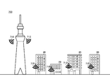
- 1 schematically shows an example of an installation environment of a plurality of base stations 100 in a system 10 according to this embodiment. An example of the beam selection function using the steering antenna in UE500 is shown roughly.
- 1 schematically shows an example of a millimeter wave network 700 devised so far.
- 1 schematically shows an example of a millimeter wave network realized by the system 10 according to the present embodiment.
- 1 schematically shows an example of a method for making an indoor area a communicable area by using scattering of radio waves by a rough surface.
- 1 schematically shows an example of a method for enabling communication inside a high-rise building.
- 1 schematically shows an example of a method of forming a communication area inside a building 50 by a base station 100.
- An example of a beam 102 launched by a base station 100 towards a building 50 is shown.
- 1 schematically shows an example of how the base station 100 radiates radio waves to a high-rise building.
- 1 schematically shows an example of a beam pattern 106 emitted from a base station 100.
- An example of a method for providing a service is schematically shown in which radio waves are scattered on a road surface and reach a lower floor of a building.
- An example of a method for providing a service is schematically shown in which radio waves are scattered on a road surface and reach a middle floor of a building.
- An example of the relay device 200 is schematically shown.
- 1 schematically shows an example of a relay device 300 for a condominium.
- 1 schematically shows an example of a reception environment in which a relay device 200 having a high gain beam steering antenna receives a radio wave emitted by a base station 100.
- 1 schematically shows an example of a link budget of rough surface scattering.
- 1 schematically shows an example of a link budget of LOS between a base station and a building window.
- 1 schematically shows an example of the functional configuration of the base station 100.
- FIG. 1 schematically shows an example of an installation environment of a plurality of base stations 100 in the system 10 according to this embodiment.
- the system 10 according to the present embodiment can execute various area building methods for building a wireless communication area.
- the base station 100 is installed outside the building, such as the roof of the building or the wall surface of the building.
- the base station 100 is not limited to being installed in a building, but may be installed in any place.
- the base station 100 is installed on a telephone pole or the like.
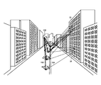
- the base station 100 forms a communication area by emitting a millimeter wave beam 102 along the road extension direction using the beam forming technique.
- the frequency band of the beam 102 emitted by the base station 100 may be any frequency band as long as it is a millimeter wave.
- the base station 100 emits a beam 102 of radio waves in the 28 GHz band, for example.
- the base station 100 also emits a beam 102 of radio waves in the 60 GHz to 80 GHz band, for example.
- the base station 100 may emit a beam 102 of radio waves in the 66 GHz band.
- the base station 100 may emit a beam 102 of radio waves in the 76 GHz band.
- the base station 100 may emit a beam 102 of radio waves in the 80 GHz band.
- FIG. 1 shows an example in which a plurality of base stations 100 are used to set a main road as a communicable area to cover a busy downtown area such as central Tokyo, for example.
- the system 10 covers the main street, which has many pedestrian streets, in a vertical, horizontal, and horizontal directions in a grid pattern, and, in principle, places it outside the area except for the building facing the street that is the target of area formation.
- An area construction method that has performed separation can be adopted.
- the system 10 according to the present embodiment targets the suburban area for the central area where many tall buildings are located, the surrounding area, and the super-rural area where no trees are planted, as the area targeted for area formation. Can adopt an area construction method that is not targeted for area formation.
- FIG. 2 schematically shows an example of the interference cancellation function of the UE 500.
- the UE 500 has a plurality of antennas.
- the UE 500 may have any number of antennas, for example, four.
- the UE 500 sets the phase of the radio wave received by each of the plurality of antennas to an appropriate angle with a phase shifter using a preset offset, and selects the preset that maximizes the desired radio wave intensity.
- This function was developed for mobile terminals, but when it is used in a UE relay or CPE, it is effective because it can be installed at a fixed point and a sufficient distance can be secured from the radio wave reflection surface and the scattering surface. In that case, on the contrary, stable gain cannot be obtained. As a result, even in a place where radio waves from the base station 100 arrive from a plurality of directions, such as an intersection in the environment shown in FIG. 1, radio waves do not interfere with each other and only desired radio waves are high. It is possible to receive with quality.
- FIG. 3 schematically shows an example of a millimeter wave network 700 devised so far.
- FIG. 4 schematically shows an example of a millimeter wave network realized by the system 10 according to the present embodiment. 3 and 4, the difference between the millimeter wave network 700 devised so far and the millimeter wave network realized by the system 10 according to the present embodiment will be described.
- the millimeter-wave network 700 devised so far, as shown in FIG. 3, emits a radio wave 710 downward from a building 20 or a building exceeding the height of an average building to cover a wide range. It was intended to be able to communicate.
- a plurality of base stations emit radio waves 710 from directly above like the millimeter wave network 700, a lot of inter-cell interference occurs.
- the millimeter wave network realized by the system 10 according to the present embodiment is horizontal from the base station 100 installed at a height equal to or lower than the average building height.
- the main communication area is only along the main road.
- the system 10 according to the present embodiment can communicate over a long distance by consolidating the energy spread in an area with no communication demand along the road with a relatively high communication demand by making the area only along the road. It is what
- the millimeter wave network 700 devised so far, a plurality of base stations will be installed to cover the area as shown in FIG. 3, and a lot of inter-cell interference will occur.
- one base station 100 covers the area as shown in FIG. 4, and no interference occurs.
- FIG. 5 schematically shows an example of a method of making an indoor area a communicable area by using radio wave scattering by a rough surface.
- the millimeter wave beam 102 emitted from the base station 100 is scattered by, for example, asphalt unevenness on the ground, and a scattered radio wave 104 reaches the inside of the building 30 through the window 32 of the building 30 along the road.
- the beam is irradiated in the direction of extension of the road, the energy scattered by the road and rough surfaces such as rough wall surfaces is small, and the component due to reflection is mainly, Since radio waves are not reflected in directions other than the direction in which the angle of incidence and the angle of reflection of radio waves are the same, almost no radio waves reached indoors. However, in millimeter waves, the energy scattered by the rough surface is large, and the energy scattered all over the road, the rough wall surface, and the like reaches the indoors in a state where all the energy is integrated. It should be noted that the reflected component is not negated, but the energy due to the scattering is added and received.
- the base station 100 may construct an outdoor area by radio waves propagating mainly through line-of-sight propagation of the beam 102 aligned in the direction of the road and specular reflection and rough surface scattering from the road surface and building wall surfaces.
- the base station 100 covers the indoor area by the line-of-sight propagation of the beam 102 aligned in the road direction and the radio waves propagated by specular reflection and rough surface scattering from the road surface and the building wall surface that are reflected or scattered toward the inside of the building. You may build.
- the road on which the base station 100 emits the millimeter wave beam 102 may be any road.
- the road may be asphalt paved.
- the size of the coarse aggregate contained in the asphalt mixture forming the asphalt pavement is, for example, 13 mm in the upper layer portion and 20 mm in the middle and lower layer portions.
- the road may be a road using a porous asphalt mixed material as an asphalt mixture.
- the road may have the filler or fine aggregate removed due to deterioration.
- the filler at the top of the road is around 5 mm, and radio waves of wavelengths shorter than that are considered to scatter well on the road surface.
- the base station 100 intentionally hits a road surface or a rough wall surface with a radio wave having a frequency band higher than the 28 GHz band within a frequency range not exceeding the usage limit of the CMOS (Complementary Metal Oxide Semiconductor) used for the output amplifier. Areas are constructed by forming a donor to the UE or CPE by scattering the rough surface.
- CMOS Complementary Metal Oxide Semiconductor
- FIG. 6 schematically shows an example of a method for enabling communication inside a high-rise building.
- the base station 100 is installed on the bank on the opposite side of the river in order to enable communication within the condominium 40 standing along the river is illustrated.
- the base station 100 emits a millimeter wave beam 102 toward the condominium 40.
- the beam 102 can penetrate the inside of the apartment 40 through the window of the apartment 40. Thereby, it is possible to directly provide the communication service indoors.
- the base station 100 may be installed on the bank on the front side of the river instead of the bank on the opposite side of the river.
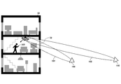
- FIG. 7 schematically shows an example of a method of forming a communication area inside the building 50 by the base station 100.
- the base station 100 is installed far away from the building 50.
- the base station 100 may be installed at a position away from the building 50 by a predetermined distance or more.
- the base station 100 is installed at an arbitrary location away from the building 50 by a predetermined distance or more.
- the beam 102 emitted by the base station 100 installed at an arbitrary location reaches the inside of the building 50 through the window 52 of the building 50.
- the beam 102 that has reached the inside of the building is reflected and scattered by the ceiling, walls, and the like, and is received by the UE 500.
- the base station 100 provides the 5G service using millimeter waves to the middle floors and the insides of the high-rise buildings in order to provide the 5G service to the high-rise buildings from a position separated by a predetermined distance or more from the high-rise buildings.
- the radio waves may penetrate into the building.
- FIG. 8 shows an example of the beam 102 emitted toward the building 50 by the base station 100.
- the base station 100 may control the beam 102 so that the beam 102 does not deviate from the building 50 regardless of the position of the beam with respect to the building 50.
- FIG. 9 schematically shows an example of a method in which the base station 100 radiates radio waves to a high-rise building.
- the base station 100 in order to avoid interference with, for example, a satellite space station or an earth station that uses frequencies close to each other, when forming a beam, uses a beam that is used according to the shape of the building 50 that radiates radio waves, and a beam that is not used. You may decide.
- the base station 100 may determine the beam 108 toward the satellite space station 90 as the unused beam.
- FIG. 10 schematically shows an example of the beam pattern 106 emitted from the base station 100.
- the base station 100 does not perform particularly difficult control, and first sweeps the beam according to a predetermined beam grid. As a result, it becomes possible to radiate radio waves to the building, high-rise building, and road located in front of the base station 100.
- Fig. 11 schematically shows an example of a method in which radio waves are scattered on a road surface, reach a lower floor of a building, and provide a service.
- the beam 102 emitted from the base station 100 is scattered on the asphalt of the road, for example, and reaches the lower floors of the building to provide a high-speed communication service inside a coffee shop or the like adjacent to the road.
- FIG. 12 schematically shows an example of a method in which radio waves are scattered on a road surface, reach a middle floor of a building, and provide a service.
- the beam 102 emitted from the base station 100 is scattered by, for example, asphalt on a road, and the radio waves scattered over a wide range are integrated and penetrate into the room through the window on the middle floor of the building to provide a high-speed communication service indoors. ..
- the communication terminal, the relay device, and the like installed near the window of the building may direct the antenna toward the road surface so that the scattered radio waves can be received most efficiently.
- FIG. 13 schematically shows an example of the relay device 200.
- the relay device 200 according to the present embodiment relays communication between the base station 100 and the indoor UE 500.
- the relay device 200 may be a UE relay. Further, the relay device 200 may be a CPE.
- the relay device 200 includes a donor antenna 222 that is an antenna for connecting to the base station 100 side and a service antenna 224 that is an antenna for an indoor side cover.
- the relay device 200 includes a relay processing unit 226 that propagates the signal propagated by the radio wave received by the donor antenna 222 to the service antenna 224.
- the relay device 200 includes a housing 210 having a donor antenna 222, a service antenna 224, and a relay processing unit 226 inside.
- the donor antenna 222 and the service antenna 224 are arranged with a cavity 212 into which a radio wave obstacle that interferes with radio wave propagation can be inserted and removed.
- the Venetian blind 64 is illustrated as the radio wave obstacle.
- the housing 210 has a U-shape as shown in FIG. 13.
- the housing 210 may have a U-shaped cross section.
- the cavity 212 is located in a U-shaped recess of the housing 210.
- the relay device 200 is arranged inside the glass door 62 indoors.
- the relay device 200 may be arranged such that the donor antenna 222 is located between the glass door 62 and the Venetian blind 64, and the service antenna 224 is located closer to the indoor side than the Venetian blind 64.
- the beam 102 reaching the glass door 62 is, for example, the beam 102 emitted by the base station 100 toward the building.
- the beam 102 reaching the glass door 62 is, for example, the beam 102 emitted by the base station 100 toward a road facing a building and scattered roughly on the road surface of the road.
- the beam 102 reaching the glass door 62 is, for example, the beam 102 emitted from the base station 100 and regularly reflected by the road surface, the building wall surface, or the like.
- the beam 102 emitted by the base station 100 reaches the glass door 62 by line-of-sight propagation, specular reflection from roads and building walls, and rough surface scattering.
- the millimeter wave beam 102 passes through the glass door 62, it penetrates indoors unless the Venetian blind 64 is installed. However, when the Venetian blind 64 is installed, the Venetian blind 64 causes the beam 102 to be lost. In particular, when the Venetian blind 64 is made of steel and is in a completely closed state, a large amount of loss occurs, and the indoor UE 500 cannot establish a stable radio link with the base station 100. I will end up.
- the beam 102 is received by the donor antenna 222 arranged between the glass door 62 and the Venetian blind 64, and the signal propagated by the beam 102 is provided as a service. Since it is emitted indoors by the radio wave 230 of the antenna 224, it is possible to eliminate such a loss due to the Venetian blind 64.
- the donor antenna 222 may be a beam steering antenna.
- the donor antenna 222 may orient the pointing direction of the antenna in the arrival direction of the beam 102.
- the service antenna 224 may output radio waves in a frequency band different from millimeter waves.
- the service antenna 224 may be a WiFi access point antenna. Further, the service antenna 224 may be an antenna of a 5G base station.
- the service antenna 224 may also be an LTE base station antenna.
- the service antenna 224 is an LTE base station antenna or a 5G base station that outputs radio waves in the 3.6 GHz band to 4.2 GHz band, which is said to be difficult to use in a wide range outdoors due to interference with satellite communication. May be the antenna of.
- the donor antenna 222 and the service antenna 224 may use the same frequency.
- the relay device 200 may operate the HetNet (Heterogeneous Network) function in order to avoid radio wave interference between the donor side and the service side.
- HetNet Heterogeneous Network
- FIG. 14 schematically shows an example of the relay device 300 for a condominium.
- the relay device 300 is placed at a position where the base station 100 can be seen, such as on the bookshelf 66.
- FIG. 15 schematically shows an example of a reception environment in which a relay device 200 having a high gain beam steering antenna receives a radio wave emitted by the base station 100.
- the relay device 200 installed in the building 50 when the base station 100 is not installed on the road 74 side, the beam 102 emitted by the base station 100 on the road 72 side is The signal transmitted by the base station 100 may be relayed to the building 50 inside the building 50 by receiving the radio waves scattered at 76 at the rough surface.
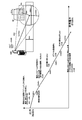
- FIG. 16 schematically shows an example of a link budget for rough surface scattering.
- an example of the link budget when the smart phone (smartphone) in the coffee shop 80 receives 102 output from the base station 100 is shown.
- the radio wave output by the base station 100 is the ratio of the irradiated road to the beam 102, the ratio of the scattered beam 102 jumping into the coffee shop 80, the aperture ratio of the window, the transmission loss of the glass, the scattering efficiency of the ceiling, and the scattered beam.
- FIG. 16 theoretically, it is possible to realize reception power that can be practically used.
- FIG. 17 schematically shows an example of the LOS link budget.
- an example of a link budget when the smartphone in the office 82 receives 102 output from the base station 100 is shown.
- the case where the office window has a size of 6 m ⁇ 2 m and the hot wire glass is used will be described as an example.
- the radio wave output by the base station 100 is attenuated by factors such as the area of the beam 102 entering the window of the office 82, the transmission loss of the heat ray glass, the scattering efficiency of the ceiling, and the rate at which the scattered beam jumps into the smartphone. Will be received. However, as shown in FIG. 17, theoretically, it is possible to realize received power that can be practically used.
- FIG. 18 schematically shows an example of the functional configuration of the base station 100.
- the base station 100 includes an antenna 110 and an antenna control unit 120.
- the antenna 110 emits a millimeter-wave radio wave beam 102 in a designated direction.
- the antenna 110 may emit the beam 102 in any frequency band of millimeter waves.
- the antenna 110 emits the beam 102 in the 28 GHz band, for example.
- the antenna 110 emits the beam 102 in the 60 GHz to 80 GHz band, for example.
- the antenna 110 may emit the beam 102 in the 60 GHz band.
- the antenna 110 may emit the beam 102 in the 76 GHz band.
- the antenna 110 may emit the beam 102 in the 80 GHz band.
- the antenna 110 may form the beam 102 by the GoB (Grid of Beam) method instead of the EBB (Eigenvalue Based Beamforming) method.
- the antenna control unit 120 controls the antenna 110.
- the antenna control unit 120 controls the antenna 110 so that the peak of the beam 102 from the antenna 110 is located on the road surface of the road, for example.
- the antenna control unit 120 may control the antenna 110 so that the peak of the beam 102 generated by the antenna 110 is located on the road surface of an asphalt paved road.
- the antenna control unit 120 may control the antenna 110 so that the peak of the beam 102 from the antenna 110 is located on the road surface of the road in order to form a communication area in the building along the road.
- the antenna control unit 120 may be able to form the communication area by the radio waves roughly scattered by the road surface of the road.
- the system 10 according to the present embodiment may include a plurality of base stations 100 and a plurality of relay devices including antennas having directivity on the road surface of the road where the peak of the beam by the base stations 100 is located.
- the relay device included in the system 10 according to the present embodiment may be the relay device 200.
- the relay device included in the system 10 according to the present embodiment may be the relay device 300.
- the downtilt is not applied, and the base area of the base station 100 is not designed to be an area, but directly to the middle floors and high floors of the building.
- a station design may be employed that also includes the incoming beam.
- the antenna control unit 120 may cause the antenna 110 to emit the beam 102 toward the building.
- the antenna controller 120 may cause the antenna 110 to emit the beam 102 directly toward the building.
- the antenna controller 120 may control the antenna 110 so that the beam 102 does not leave the building.
- the base station 100 may further include a direction acquisition unit (not shown) that acquires the direction of the satellite space station or the earth station, starting from the base station 100.
- the direction acquisition unit may store in advance the position information of the satellite space station and the position information of the earth station, and may acquire the direction from these position information and the position information of the base station 100.
- the antenna control unit 120 may control the antenna 110 so that the beam 102 from the antenna 110 is not directed in the direction acquired by the direction acquisition unit.
- the antenna control unit 120 selects, for example, the beam 102 that does not match the direction acquired by the direction acquisition unit as the beam 102 that does not use, and uses the beam 102 that does not match the direction acquired by the direction acquisition unit. Beam 102 to be selected.
- the base station 100 may have an output amplifier including a CMOS, and may output a radio wave having a bandwidth of a frequency higher than the 28 GHz band within an output range that does not exceed the usage limit of the CMOS.
- the base station 100 may be installed at a position as high as possible in order to secure LOS (Line of Sight). For example, the base station 100 is installed at a position higher than a predetermined height. Then, the base station 100 may construct a communication area by LOS or semiLOS by projecting the beam 102 toward the road extending direction by the GoB method from a position higher than a predetermined height.
- LOS Line of Sight
- the base station 100 may be installed in a building. When installed in a building located at a crossroad, the base station 100 may have a sector configuration of 2 sectors or 4 sectors in the road extension direction. When installed in a building located on a three-forked road, the base station 100 may have a sector configuration of three sectors.
- the base station 100 constructs an area with a scheme that is completely different from that of a normal repeating 3-sector station.
- a digital precoding circuit for emitting a plurality of beams is not provided in front of the analog front end, and the GoB system beamforming is adopted instead of the EBB system beamforming.
- the precoding circuit may be eliminated. Thereby, the cost can be reduced.
- the base station 100 As a wireless device of the base station 100, it supports MIMO, but does not support Massive MIMO, so that the digital precoding circuit is omitted, and the PA (Power Amplifier), LNA (Low Noise Amplifier), and phase shifter are directly output from the modem. You may use a radio connected to.
- MIMO Massive MIMO
- PA Power Amplifier
- LNA Low Noise Amplifier
- phase shifter are directly output from the modem. You may use a radio connected to.
- the base station 100 may be operated as an IP base station without adopting the CPRI, and the communication speed is suppressed by transmitting a single beam instead of a multi-beam, whereby the 10 GBASE SFP (Small Form Factor Pluggable) 1 One can be operational.
- SFP Small Form Factor Pluggable
- the base station 100 does not require a CPRI interface and a BBU (Base Band Unit) that processes a plurality of antenna streams by removing the digital precoding circuit from the configuration of an existing wireless base station.
- BBU Base Band Unit
- a base station operating only with an IP interface may be used.
- a plurality of base stations 100 may emit one beam per base station 100 when directly irradiating a building with radio waves.
- the base station 100 may emit one beam by a combination of vertical polarization and horizontal polarization, or a combination of + 45 ° and ⁇ 45 ° polarization.
- a U-shaped UE relay or CPE equipped with a high-gain beam steering antenna is provided by a beam design method that sets the beam for all line-of-sight locations other than the sky, regardless of the building wall surface, road surface, or rooftop surface.
- a U-shaped UE relay or CPE equipped with a beam steering antenna with a higher gain dedicated to reception the rough surface scattered waves and regular reflection waves on the road surface or rough wall surface are added to secure the maximum place ratio.
- An area construction method using the station placement design method may be executed.
- the system 10 uses a DL (Down Link) only link, which is expected to be specified in Release 17 of 3GPP in the future, and has a receive-only beam steering antenna with higher gain (30 dBi, etc.). Stable using a U-shaped UE relay or CPE, using rough surface scattering or reflected waves on a distant road surface or rough wall (a wide area can be pinpointed because it is far) Area building method that secures various link budgets may be executed.
- DL Down Link
- radio waves emitted from the base station 100 enter through the window of the condominium and are reflected once by Lambert on the ceiling of the room.
- the user of the UE 500 may be allowed to install it in a place where the reception radio field intensity of the UE relay is the strongest.
- the base station 100 in the system 10 according to the present embodiment is basically composed of two sectors, but in the case of projecting a beam to the middle floor and high floors of a building, the base station 100 is divided into the above-mentioned two sectors and the middle floor or high floor.
- the target sector is added to 3 sectors, and the area inside the building is created by irradiating the building from the surrounding 2 and 3 directions, but the beam is not directed to the direction where the building is not standing, and it is continuous.
- Area building methods that do not build large areas may be adopted. Areas where buildings are dense may have a 2- or 4-sector structure on the main road, and narrow roads may not be given up as areas.
- the 28 GHz band is characterized in that the area outside the line of sight such as a sub urban area or a narrow back alley is not targeted for the area. Therefore, the location rate may be calculated by considering only the target area.
- a provider such as a telecommunications carrier who provides the system 10 according to the present embodiment is required to install the U-shaped UE relay or CPE used in the system 10 according to the present embodiment before installing the U-shaped UE relay or CPE on the middle floor or the high floor.
- the CPE or the UE relay may be installed on each of the four sides of the building at a place where the customer has gone to the business so that the CPE or the UE relay is installed in a place where the quality is good.
- the radio wave emitted from the base station 100 is reflected once or twice by the rough wall surface of the building to reach an area outside the line of sight, and the UE directs the beam upward from the horizon.
- the signal may be received by a relay, which can reduce the influence of an automobile or a pedestrian traveling on the ground and improve the quality of communication.
Landscapes
- Engineering & Computer Science (AREA)
- Computer Networks & Wireless Communication (AREA)
- Signal Processing (AREA)
- Mobile Radio Communication Systems (AREA)
- Radio Relay Systems (AREA)
Abstract
Priority Applications (3)
| Application Number | Priority Date | Filing Date | Title |
|---|---|---|---|
| GB2106231.0A GB2593312B (en) | 2018-11-05 | 2019-10-07 | Area construction method |
| JP2020556699A JP7500431B2 (ja) | 2018-11-05 | 2019-10-07 | エリア構築方法 |
| US17/244,967 US11997506B2 (en) | 2018-11-05 | 2021-04-30 | Area construction method |
Applications Claiming Priority (2)
| Application Number | Priority Date | Filing Date | Title |
|---|---|---|---|
| JP2018208065 | 2018-11-05 | ||
| JP2018-208065 | 2018-11-05 |
Related Child Applications (1)
| Application Number | Title | Priority Date | Filing Date |
|---|---|---|---|
| US17/244,967 Continuation US11997506B2 (en) | 2018-11-05 | 2021-04-30 | Area construction method |
Publications (1)
| Publication Number | Publication Date |
|---|---|
| WO2020095597A1 true WO2020095597A1 (fr) | 2020-05-14 |
Family
ID=70610956
Family Applications (1)
| Application Number | Title | Priority Date | Filing Date |
|---|---|---|---|
| PCT/JP2019/039512 Ceased WO2020095597A1 (fr) | 2018-11-05 | 2019-10-07 | Procédé de construction de zone |
Country Status (4)
| Country | Link |
|---|---|
| US (1) | US11997506B2 (fr) |
| JP (1) | JP7500431B2 (fr) |
| GB (1) | GB2593312B (fr) |
| WO (1) | WO2020095597A1 (fr) |
Cited By (16)
| Publication number | Priority date | Publication date | Assignee | Title |
|---|---|---|---|---|
| WO2022155529A1 (fr) * | 2021-01-15 | 2022-07-21 | Pivotal Commware, Inc. | Installation de répéteurs pour un réseau de communication à ondes millimétriques |
| US11497050B2 (en) | 2021-01-26 | 2022-11-08 | Pivotal Commware, Inc. | Smart repeater systems |
| US11563279B2 (en) | 2020-01-03 | 2023-01-24 | Pivotal Commware, Inc. | Dual polarization patch antenna system |
| CN115696351A (zh) * | 2021-07-30 | 2023-02-03 | 中国移动通信有限公司研究院 | 基站覆盖范围的确定方法、装置、设备及存储介质 |
| US11670849B2 (en) | 2020-04-13 | 2023-06-06 | Pivotal Commware, Inc. | Aimable beam antenna system |
| US11706722B2 (en) | 2018-03-19 | 2023-07-18 | Pivotal Commware, Inc. | Communication of wireless signals through physical barriers |
| US11757180B2 (en) | 2019-02-20 | 2023-09-12 | Pivotal Commware, Inc. | Switchable patch antenna |
| US11844050B2 (en) | 2020-09-08 | 2023-12-12 | Pivotal Commware, Inc. | Installation and activation of RF communication devices for wireless networks |
| US11848478B2 (en) | 2019-02-05 | 2023-12-19 | Pivotal Commware, Inc. | Thermal compensation for a holographic beam forming antenna |
| US11929822B2 (en) | 2021-07-07 | 2024-03-12 | Pivotal Commware, Inc. | Multipath repeater systems |
| US11937199B2 (en) | 2022-04-18 | 2024-03-19 | Pivotal Commware, Inc. | Time-division-duplex repeaters with global navigation satellite system timing recovery |
| US11968593B2 (en) | 2020-08-03 | 2024-04-23 | Pivotal Commware, Inc. | Wireless communication network management for user devices based on real time mapping |
| US11973568B2 (en) | 2020-05-27 | 2024-04-30 | Pivotal Commware, Inc. | RF signal repeater device management for 5G wireless networks |
| WO2024171832A1 (fr) * | 2023-02-14 | 2024-08-22 | Agc株式会社 | Dispositif de communication sans fil |
| US12185453B2 (en) | 2021-10-26 | 2024-12-31 | Pivotal Commware, Inc. | RF absorbing structures |
| US12574101B2 (en) | 2020-08-31 | 2026-03-10 | Wollochet Solutions Llc | Location dependent relay node configuration |
Families Citing this family (11)
| Publication number | Priority date | Publication date | Assignee | Title |
|---|---|---|---|---|
| US11272861B1 (en) * | 2012-09-25 | 2022-03-15 | Micro Mobio Corporation | Personal cloud with a plurality of modular capabilities |
| US11877842B1 (en) | 2012-09-25 | 2024-01-23 | Micro Mobio Corporation | Personal cloud with a plurality of modular capabilities |
| US12150755B1 (en) | 2012-09-25 | 2024-11-26 | Micro Mobio Corporation | Integrated display with antenna system and method |
| CA3106147A1 (fr) * | 2018-07-11 | 2020-01-16 | Sail Internet, Inc. | Procede et appareil pour qualifier des clients et concevoir un reseau sans fil fixe a l'aide de donnees de mappage |
| EP3868142A4 (fr) | 2018-10-16 | 2022-07-20 | Sail Internet, Inc. | Procédé et appareil d'évaluation d'une fréquence radio pour une utilisation dans une zone cellulaire d'un réseau sans fil |
| WO2020123208A1 (fr) * | 2018-12-10 | 2020-06-18 | Sail Internet, Inc. | Procédé et appareil de conception d'un réseau sans fil |
| US12463322B1 (en) | 2019-04-03 | 2025-11-04 | Micro Mobio Corporation | Antenna in display |
| US11832328B2 (en) * | 2020-04-22 | 2023-11-28 | Qualcomm Incorporated | Control link for low-power and simplified transceiver |
| TR2021019907A2 (tr) * | 2021-12-14 | 2022-02-21 | Univ Istanbul Medipol | Mi̇li̇metre dalga ve terahertz frekanslarinda pürüzlü ve düzgün yüzeyler kullanilarak bi̇rleşi̇k algilama ve i̇leti̇şi̇me yöneli̇k yeni̇ bi̇r yöntem |
| US11683090B1 (en) | 2022-01-18 | 2023-06-20 | T-Mobile Usa, Inc. | Laser-based enhancement of signal propagation path for mobile communications |
| CN117278935B (zh) * | 2023-11-04 | 2024-06-18 | 天宇正清科技有限公司 | 基站选址的方法、装置、电子设备及可读存储介质 |
Citations (3)
| Publication number | Priority date | Publication date | Assignee | Title |
|---|---|---|---|---|
| JP2010157944A (ja) * | 2008-12-31 | 2010-07-15 | Tohoku Univ | 指向性を制御可能なアンテナを用いた無線通信システムおよびその受信装置 |
| JP2010268254A (ja) * | 2009-05-15 | 2010-11-25 | Hitachi Ltd | 無線局配置探索装置 |
| WO2018168110A1 (fr) * | 2017-03-13 | 2018-09-20 | パナソニックIpマネジメント株式会社 | Dispositif de communication sans fil, procédé de communication sans fil, et bâtiment équipé d'un dispositif de communication sans fil |
Family Cites Families (14)
| Publication number | Priority date | Publication date | Assignee | Title |
|---|---|---|---|---|
| JPH01158836A (ja) * | 1987-12-15 | 1989-06-21 | Mitsubishi Electric Corp | 無線中継装置 |
| JP3548880B2 (ja) | 1997-08-26 | 2004-07-28 | カシオ計算機株式会社 | 印字装置 |
| JPH11163773A (ja) * | 1997-11-25 | 1999-06-18 | Hitachi Electron Service Co Ltd | 建屋内無電源電波中継器 |
| US6640089B1 (en) * | 2000-11-13 | 2003-10-28 | Verizon Laboratories Inc. | System and method for adaptively predicting radio wave propagation |
| WO2007136289A1 (fr) * | 2006-05-23 | 2007-11-29 | Intel Corporation | Systèmes d'antennes à réseau de puces et de lentilles à ondes millimétriques pour réseaux sans fil |
| KR20140042978A (ko) * | 2012-09-28 | 2014-04-08 | 한국전자통신연구원 | 전파 시스템에서 전자파 프로파게이션 분석 장치 및 방법 |
| US10014948B2 (en) * | 2014-04-04 | 2018-07-03 | Nxgen Partners Ip, Llc | Re-generation and re-transmission of millimeter waves for building penetration |
| US10958332B2 (en) * | 2014-09-08 | 2021-03-23 | Mimosa Networks, Inc. | Wi-Fi hotspot repeater |
| CN105992329B (zh) * | 2015-02-27 | 2019-09-06 | 展讯通信(上海)有限公司 | 信号放大装置及其控制方法、识别信号放大装置的方法 |
| JP2018033121A (ja) | 2016-04-19 | 2018-03-01 | 株式会社村田製作所 | 通信ユニット |
| US10425159B2 (en) * | 2016-06-07 | 2019-09-24 | Siklu Communication ltd. | Systems and methods for communicating through a glass window barrier |
| CN110521277A (zh) * | 2017-03-22 | 2019-11-29 | 尼克根合伙Ip有限责任公司 | 用于建筑物穿透的毫米波的再生与转发 |
| US10736074B2 (en) * | 2017-07-31 | 2020-08-04 | Qualcomm Incorporated | Systems and methods to facilitate location determination by beamforming of a positioning reference signal |
| US11509366B2 (en) * | 2018-10-10 | 2022-11-22 | Telefonaktiebolaget Lm Ericsson (Publ) | Hybrid FD-MIMO: combining codebook-based and reciprocity-based beamforming |
-
2019
- 2019-10-07 WO PCT/JP2019/039512 patent/WO2020095597A1/fr not_active Ceased
- 2019-10-07 GB GB2106231.0A patent/GB2593312B/en active Active
- 2019-10-07 JP JP2020556699A patent/JP7500431B2/ja active Active
-
2021
- 2021-04-30 US US17/244,967 patent/US11997506B2/en active Active
Patent Citations (3)
| Publication number | Priority date | Publication date | Assignee | Title |
|---|---|---|---|---|
| JP2010157944A (ja) * | 2008-12-31 | 2010-07-15 | Tohoku Univ | 指向性を制御可能なアンテナを用いた無線通信システムおよびその受信装置 |
| JP2010268254A (ja) * | 2009-05-15 | 2010-11-25 | Hitachi Ltd | 無線局配置探索装置 |
| WO2018168110A1 (fr) * | 2017-03-13 | 2018-09-20 | パナソニックIpマネジメント株式会社 | Dispositif de communication sans fil, procédé de communication sans fil, et bâtiment équipé d'un dispositif de communication sans fil |
Non-Patent Citations (2)
| Title |
|---|
| KISHIYAMA, YOSHIHISA ET AL.: "Special Issue on 5G Technology for services implementation in 2020", NTT DOCOMO TECHNICAL JOURNAL, vol. 23, no. 4, January 2016 (2016-01-01), pages 6 - 48, XP055706031, Retrieved from the Internet <URL:https://www.nttdocomo.co.jp/binary/pdf/corporate/technology/rd/technical_journal/bn/vol23_4/vol23_4_000jp.pdf> [retrieved on 20191209] * |
| UMEKI , KENTO: "Mm-Wave Channel Model Considering Surrounding Wall Reflection For Outdoor Open Area Access Environments", IEICE TECHNICAL REPORT, vol. 116, no. 481, March 2017 (2017-03-01) * |
Cited By (21)
| Publication number | Priority date | Publication date | Assignee | Title |
|---|---|---|---|---|
| US11706722B2 (en) | 2018-03-19 | 2023-07-18 | Pivotal Commware, Inc. | Communication of wireless signals through physical barriers |
| US12425987B2 (en) | 2018-03-19 | 2025-09-23 | Pivotal Commware, Inc. | Communication of wireless signals through physical barriers |
| US11848478B2 (en) | 2019-02-05 | 2023-12-19 | Pivotal Commware, Inc. | Thermal compensation for a holographic beam forming antenna |
| US11757180B2 (en) | 2019-02-20 | 2023-09-12 | Pivotal Commware, Inc. | Switchable patch antenna |
| US12362472B2 (en) | 2019-02-20 | 2025-07-15 | Pivotal Commware, Inc. | Switchable patch antenna |
| US11563279B2 (en) | 2020-01-03 | 2023-01-24 | Pivotal Commware, Inc. | Dual polarization patch antenna system |
| US11670849B2 (en) | 2020-04-13 | 2023-06-06 | Pivotal Commware, Inc. | Aimable beam antenna system |
| US11973568B2 (en) | 2020-05-27 | 2024-04-30 | Pivotal Commware, Inc. | RF signal repeater device management for 5G wireless networks |
| US11968593B2 (en) | 2020-08-03 | 2024-04-23 | Pivotal Commware, Inc. | Wireless communication network management for user devices based on real time mapping |
| US12574101B2 (en) | 2020-08-31 | 2026-03-10 | Wollochet Solutions Llc | Location dependent relay node configuration |
| US11844050B2 (en) | 2020-09-08 | 2023-12-12 | Pivotal Commware, Inc. | Installation and activation of RF communication devices for wireless networks |
| US11843955B2 (en) | 2021-01-15 | 2023-12-12 | Pivotal Commware, Inc. | Installation of repeaters for a millimeter wave communications network |
| WO2022155529A1 (fr) * | 2021-01-15 | 2022-07-21 | Pivotal Commware, Inc. | Installation de répéteurs pour un réseau de communication à ondes millimétriques |
| US11497050B2 (en) | 2021-01-26 | 2022-11-08 | Pivotal Commware, Inc. | Smart repeater systems |
| US12010703B2 (en) | 2021-01-26 | 2024-06-11 | Pivotal Commware, Inc. | Smart repeater systems |
| US11929822B2 (en) | 2021-07-07 | 2024-03-12 | Pivotal Commware, Inc. | Multipath repeater systems |
| CN115696351A (zh) * | 2021-07-30 | 2023-02-03 | 中国移动通信有限公司研究院 | 基站覆盖范围的确定方法、装置、设备及存储介质 |
| US12185453B2 (en) | 2021-10-26 | 2024-12-31 | Pivotal Commware, Inc. | RF absorbing structures |
| US11937199B2 (en) | 2022-04-18 | 2024-03-19 | Pivotal Commware, Inc. | Time-division-duplex repeaters with global navigation satellite system timing recovery |
| US12495377B2 (en) | 2022-04-18 | 2025-12-09 | Pivotal Commware, Inc. | Time-division-duplex repeaters with global navigation satellite system timing recovery |
| WO2024171832A1 (fr) * | 2023-02-14 | 2024-08-22 | Agc株式会社 | Dispositif de communication sans fil |
Also Published As
| Publication number | Publication date |
|---|---|
| GB2593312B (en) | 2023-03-15 |
| JP7500431B2 (ja) | 2024-06-17 |
| JPWO2020095597A1 (ja) | 2021-10-07 |
| US20210250778A1 (en) | 2021-08-12 |
| GB2593312A (en) | 2021-09-22 |
| GB202106231D0 (en) | 2021-06-16 |
| US11997506B2 (en) | 2024-05-28 |
Similar Documents
| Publication | Publication Date | Title |
|---|---|---|
| US11997506B2 (en) | Area construction method | |
| Coldrey et al. | Non-line-of-sight small cell backhauling using microwave technology | |
| Khan et al. | mmWave mobile broadband (MMB): Unleashing the 3–300GHz spectrum | |
| CA2393552C (fr) | Reseau de transmission cellulaire a zone de couverture d'espace tridimensionel | |
| US8686909B2 (en) | Vault antenna for WLAN or cellular application | |
| Larsson et al. | An outdoor-to-indoor propagation scenario at 28 GHz | |
| US20050250503A1 (en) | Wireless networks frequency reuse distance reduction | |
| Du et al. | 5G E-band backhaul system measurements in urban street-level scenarios | |
| Petosa et al. | Characterization and enhancement of the environment for 5G millimetre-wave broadband mobile communications | |
| Goto et al. | Experimental trials with combination of multiple transmissive metasurfaces and beamforming for mmW coverage enhancement | |
| Park et al. | Window-type and AR glass-type transparent antenna systems for B5G/6G | |
| CN109587694B (zh) | 一种提高城中村信号覆盖的方法及电子设备 | |
| Sheikh et al. | Performance analysis of vertical and higher order sectorization in urban environment at 28 GHz | |
| KR20120099555A (ko) | 각도 다이버시티 안테나 기능을 갖는 승강기의 이동통신 중계장치 및 구성방법 | |
| CN115767564A (zh) | 一种5g移动网络覆盖系统及方法 | |
| Seltzer | Indoor coverage requirements and solutions | |
| Coldrey et al. | Non-line-of-sight microwave backhaul in heterogeneous networks | |
| Letourneux et al. | 3D propagation and environment modeling for NLOS wireless small-cell backhaul | |
| Larsson et al. | Angular Resolved Pathloss Measurements in a US Suburban Scenario at 28 GHz | |
| Rasekh et al. | Interference Analysis in an Urban Mesh Network Operating in the 60‐GHz Band | |
| CN207038723U (zh) | 天线装置及路灯天线 | |
| RU2196388C2 (ru) | Способ построения беспроводной системы доступа к сетям связи | |
| Gurung et al. | Antenna system in cellular mobile Communication | |
| Sadri et al. | The Future of Wireless: Technologies Overcoming 5G Struggles. | |
| US20230107864A1 (en) | System and method for providing broad band local area network services at a dwelling |
Legal Events
| Date | Code | Title | Description |
|---|---|---|---|
| 121 | Ep: the epo has been informed by wipo that ep was designated in this application |
Ref document number: 19882440 Country of ref document: EP Kind code of ref document: A1 |
|
| ENP | Entry into the national phase |
Ref document number: 2020556699 Country of ref document: JP Kind code of ref document: A |
|
| ENP | Entry into the national phase |
Ref document number: 202106231 Country of ref document: GB Kind code of ref document: A Free format text: PCT FILING DATE = 20191007 |
|
| WWE | Wipo information: entry into national phase |
Ref document number: 2106231.0 Country of ref document: GB |
|
| NENP | Non-entry into the national phase |
Ref country code: DE |
|
| 122 | Ep: pct application non-entry in european phase |
Ref document number: 19882440 Country of ref document: EP Kind code of ref document: A1 |
|
| WWG | Wipo information: grant in national office |
Ref document number: 2106231.0 Country of ref document: GB |