WO2020095653A1 - 塗布装置 - Google Patents
塗布装置 Download PDFInfo
- Publication number
- WO2020095653A1 WO2020095653A1 PCT/JP2019/041082 JP2019041082W WO2020095653A1 WO 2020095653 A1 WO2020095653 A1 WO 2020095653A1 JP 2019041082 W JP2019041082 W JP 2019041082W WO 2020095653 A1 WO2020095653 A1 WO 2020095653A1
- Authority
- WO
- WIPO (PCT)
- Prior art keywords
- coating
- dispenser
- respect
- detected
- inclination
- Prior art date
- Legal status (The legal status is an assumption and is not a legal conclusion. Google has not performed a legal analysis and makes no representation as to the accuracy of the status listed.)
- Ceased
Links
Images


Classifications
-
- B—PERFORMING OPERATIONS; TRANSPORTING
- B05—SPRAYING OR ATOMISING IN GENERAL; APPLYING FLUENT MATERIALS TO SURFACES, IN GENERAL
- B05C—APPARATUS FOR APPLYING FLUENT MATERIALS TO SURFACES, IN GENERAL
- B05C11/00—Component parts, details or accessories not specifically provided for in groups B05C1/00 - B05C9/00
- B05C11/10—Storage, supply or control of liquid or other fluent material; Recovery of excess liquid or other fluent material
- B05C11/1002—Means for controlling supply, i.e. flow or pressure, of liquid or other fluent material to the applying apparatus, e.g. valves
- B05C11/1015—Means for controlling supply, i.e. flow or pressure, of liquid or other fluent material to the applying apparatus, e.g. valves responsive to a conditions of ambient medium or target, e.g. humidity, temperature ; responsive to position or movement of the coating head relative to the target
- B05C11/1018—Means for controlling supply, i.e. flow or pressure, of liquid or other fluent material to the applying apparatus, e.g. valves responsive to a conditions of ambient medium or target, e.g. humidity, temperature ; responsive to position or movement of the coating head relative to the target responsive to distance of target
-
- B—PERFORMING OPERATIONS; TRANSPORTING
- B05—SPRAYING OR ATOMISING IN GENERAL; APPLYING FLUENT MATERIALS TO SURFACES, IN GENERAL
- B05C—APPARATUS FOR APPLYING FLUENT MATERIALS TO SURFACES, IN GENERAL
- B05C11/00—Component parts, details or accessories not specifically provided for in groups B05C1/00 - B05C9/00
- B05C11/10—Storage, supply or control of liquid or other fluent material; Recovery of excess liquid or other fluent material
-
- B—PERFORMING OPERATIONS; TRANSPORTING
- B05—SPRAYING OR ATOMISING IN GENERAL; APPLYING FLUENT MATERIALS TO SURFACES, IN GENERAL
- B05C—APPARATUS FOR APPLYING FLUENT MATERIALS TO SURFACES, IN GENERAL
- B05C5/00—Apparatus in which liquid or other fluent material is projected, poured or allowed to flow on to the surface of the work
- B05C5/02—Apparatus in which liquid or other fluent material is projected, poured or allowed to flow on to the surface of the work the liquid or other fluent material being discharged through an outlet orifice by pressure, e.g. from an outlet device in contact or almost in contact, with the work
- B05C5/0204—Apparatus in which liquid or other fluent material is projected, poured or allowed to flow on to the surface of the work the liquid or other fluent material being discharged through an outlet orifice by pressure, e.g. from an outlet device in contact or almost in contact, with the work for applying liquid or other fluent material to the edges of essentially flat articles
-
- B—PERFORMING OPERATIONS; TRANSPORTING
- B05—SPRAYING OR ATOMISING IN GENERAL; APPLYING FLUENT MATERIALS TO SURFACES, IN GENERAL
- B05C—APPARATUS FOR APPLYING FLUENT MATERIALS TO SURFACES, IN GENERAL
- B05C5/00—Apparatus in which liquid or other fluent material is projected, poured or allowed to flow on to the surface of the work
- B05C5/02—Apparatus in which liquid or other fluent material is projected, poured or allowed to flow on to the surface of the work the liquid or other fluent material being discharged through an outlet orifice by pressure, e.g. from an outlet device in contact or almost in contact, with the work
- B05C5/0208—Apparatus in which liquid or other fluent material is projected, poured or allowed to flow on to the surface of the work the liquid or other fluent material being discharged through an outlet orifice by pressure, e.g. from an outlet device in contact or almost in contact, with the work for applying liquid or other fluent material to separate articles
- B05C5/0212—Apparatus in which liquid or other fluent material is projected, poured or allowed to flow on to the surface of the work the liquid or other fluent material being discharged through an outlet orifice by pressure, e.g. from an outlet device in contact or almost in contact, with the work for applying liquid or other fluent material to separate articles only at particular parts of the articles
- B05C5/0216—Apparatus in which liquid or other fluent material is projected, poured or allowed to flow on to the surface of the work the liquid or other fluent material being discharged through an outlet orifice by pressure, e.g. from an outlet device in contact or almost in contact, with the work for applying liquid or other fluent material to separate articles only at particular parts of the articles by relative movement of article and outlet according to a predetermined path
Definitions
- Patent Document 1 discloses a sealer application device for applying a sealer to the peripheral portion of the windshield of an automobile.
- An example of the coating apparatus according to the present disclosure is An ejection port capable of ejecting a liquid from a vertical direction to a coating region provided on the outer peripheral edge of the coating surface of a coating object having a coating surface, and a vertical distance between the ejection port and the coating region are detected.
- FIG. 6 is a plan view showing a corrected coating path of a coating object.
- the side view of a coating object The flowchart for demonstrating the coating process of the coating device of FIG.
- a coating device 1 includes a dispenser 10, a drive device 20 that can drive the dispenser 10, and a control device 30 that controls the dispenser 10 and the drive device 20. There is.
- the drive device 20 is, for example, a robot, holds the dispenser 10 in a state in which the liquid can be ejected from the ejection port 111 in the vertical direction Z, and the horizontal direction X, Y (see FIG. 2) and the vertical direction Z (see FIG. 3). (See) can be moved.
- the dispenser movement control unit 31 moves the dispenser 10 along a predetermined application route R1 for each application target 100. Further, as described below, when the coating path R1 is corrected by the coating path correction unit 33, the dispenser 10 is moved along the corrected coating path R2 (see FIG. 4).
- the inclination detection unit 32 based on the distance D detected by the displacement sensor 12, the inclination ⁇ of the application surface 101 with respect to the reference plane P (in this embodiment, a horizontal plane) extending in the direction intersecting the vertical direction Z (see FIG. 5). ) Is detected.
- the inclination detection unit 32 includes at least three preset positions (for example, points A, B, and C shown in FIG. 2) on the outer peripheral edge of the application surface 101 of the reference application object 100 and on the application path R1. ), And at least three preset positions on the outer peripheral edge of the coating surface 101 of the coating object 100 and on the coating path R1 (that is, points A, B and C shown in FIG. 4).
- the inclination detection unit 32 detects the inclination ⁇ of the coating surface 101 with respect to the reference plane P based on the detected distance D2 and the preset reference distance D1 (step S2). Then, the control device 30 determines whether or not the coating surface 101 is tilted with respect to the reference plane P based on whether or not the tilt ⁇ of the coating surface 101 with respect to the reference plane P is detected by the tilt detection unit 32. (Step S3).
- the application path correction unit 33 corrects the application path R1 based on the detected inclination ⁇ of the application surface 101 with respect to the reference surface P (Ste S4). Then, the dispenser movement control unit 31 moves the dispenser 10 along the corrected coating route R2 (step S5). On the other hand, when it is determined that the coating surface 101 is not tilted with respect to the reference plane P, the dispenser movement control unit 31 moves the dispenser 10 along the coating path R1 (step S6).
- the coating apparatus 1 the inclination ⁇ of the coating surface 101 with respect to the reference plane P extending in the direction intersecting the vertical direction Z is detected based on the distance D detected by the displacement sensor 12, and the detected coating surface 101 is detected.
- the coating path R1 is corrected based on the inclination ⁇ .
- the positions on the coating paths R1 and R2 where the distances D1 and D2 are detected by the inclination detection unit 32 may be two, or may not be the outer peripheral edge of the coating surface 101.
- the application surface 101 is not limited to a substantially rectangular shape and may have any shape.
- the application area 102 is not limited to the outer peripheral edge of the application surface 101, and can be set arbitrarily.
- the dispenser movement control unit 31 is configured to move the dispenser 10 at a different speed when the coating surface 101 is tilted with respect to the reference plane P and when the coating surface 101 is not tilted with respect to the reference plane P. be able to.
- the reference plane P is a horizontal plane
- the coating surface 101 is inclined with respect to the horizontal plane, a smaller speed than when the coating surface 101 is horizontal. The dispenser 10 is moved with.
- the dispenser movement control unit 31 causes the dispenser 10 to move at a speed of VCos ⁇ . To move.
- a line having substantially the same width as the reference line formed by the liquid discharged along the coating path R1 of the reference coating object 100 can be formed on the corrected coating path R2 of the coating object 100. it can.
- the dispenser movement control unit 31 is different from the case where the application surface 101 is not inclined with respect to the reference plane P when the inclination of the application surface 101 with respect to the reference plane P detected by the inclination detection unit 32 is equal to or more than a threshold value. It can be configured to move the dispenser 10 at a speed. This makes it possible to simplify the coating process and reduce the load on the control device 30 when performing the coating process.
- the threshold value is, for example, whether or not the coating locus can be drawn substantially the same as when the coating surface 101 is not tilted with respect to the reference plane P even if the coating surface 101 is tilted with respect to the reference plane P. Is determined from the perspective of.
- the coating apparatus 1 can be configured so as to be able to correct not only a shift with respect to the inclination ⁇ of the coating surface 101 with respect to the reference plane P but also a rotation shift on a horizontal plane and a vertical shift.
- the rotational deviation on the horizontal plane and the vertical deviation for example, the position and orientation of the reference application object 100 detected by the image sensor 40 are set as the reference position and the reference orientation, and the reference position is set. And the reference attitude and the position and attitude of the coating object 100 detected by the image sensor 40.
- a dispenser 10 having a displacement sensor 12 for detecting the distances D1 and D2 in the direction Z, A drive device 20 for driving the dispenser 10, A dispenser movement control unit 31 that controls the drive device 20 to move the dispenser 10 along a predetermined coating path R1; An inclination detection unit 32 that detects an inclination of the coating surface 101 with respect to a reference plane P extending in a direction intersecting the vertical direction Z based on the distances D1 and D2 detected by the displacement sensor 12, A coating path correction unit 33 that corrects the coating path R1 based on the tilt of the coating surface 101 detected by the tilt detection unit 32, When the coating path correction unit 33 corrects the coating path R1, the dispenser movement control unit 31 moves the dispenser 10 along the corrected coating path R2.
- the inclination ⁇ of the coating surface 101 with respect to the reference plane P extending in the direction intersecting the vertical direction Z is detected and detected based on the distance D detected by the displacement sensor 12.
- the coating path R1 is corrected based on the inclination ⁇ of the coating surface 101.
- the coating apparatus 1 is The tilt detector 32 The inclination of the coating surface 101 is detected based on the distances D1 and D2 detected at the outer peripheral edge of the coating surface 101 and at least three locations on the coating paths R1 and R2.
- the inclination ⁇ of the coating surface 101 with respect to the reference plane P can be detected more accurately.
- the coating apparatus 1 is The dispenser movement control unit 31 When the coating surface 101 is tilted with respect to the reference plane P, the dispenser 10 is moved at a speed different from that when the coating surface 101 is not tilted with respect to the reference plane P.
- the reference line formed by the liquid discharged along the coating path R1 of the reference coating object 100 on the corrected coating path R2 of the coating object 100 is substantially the same. Lines of width can be formed.
- the coating apparatus 1 is When the inclination of the coating surface 101 with respect to the reference plane P detected by the inclination detection unit 32 is equal to or more than a threshold value, the dispenser is operated at a speed different from that when the coating surface 101 is not inclined with respect to the reference plane P. Move 10
- the coating device 1 of the fourth aspect it is possible to simplify the coating process and reduce the load on the control device 30 when performing the coating process.
- the reference line formed by the liquid discharged along the coating route R1 of the reference coating target 100 on the corrected coating route R2 of the coating target 100 is substantially the same. Lines of width can be formed.
- the coating device of the present disclosure can be used, for example, for coating a sealer on windshield glass.
Landscapes
- Coating Apparatus (AREA)
- Application Of Or Painting With Fluid Materials (AREA)
Abstract
塗布装置が、塗布領域に鉛直方向から液体を吐出可能な吐出口と、吐出口と塗布領域との間の鉛直方向の距離を検出する変位センサとを有するディスペンサと、ディスペンサを駆動する駆動装置と、予め定められている塗布経路に沿ってディスペンサを移動させるディスペンサ移動制御部と、変位センサにより検出された距離に基づいて基準面に対する塗布面の傾きを検出する傾き検出部と、傾き検出部により検出された塗布面の傾きに基づいて塗布経路を補正する塗布経路補正部とを備える。
Description
本開示は、塗布装置に関する。
特許文献1には、自動車のウインドガラスの周縁部にシーラーを塗布するためのシーラー塗布装置が開示されている。
前記シーラー塗布装置では、ウインドガラスが、水平面に沿って移動するベルトコンベアから鉛直方向に延びるワーク保持部によって、水平面に対して傾かないように保持されている。このため、このようなシーラー塗布装置においてウインドガラスの位置ずれを補正する場合、通常、ウインドガラスの水平面上の回転ずれ、あるいは、ウインドガラスの鉛直方向のずれについては考慮されるが、ウインドガラスの水平面に対する傾きついては考慮されない。
本開示は、塗布面が水平面に対して傾いていたとしても、塗布面の所定の位置に液体を正確に塗布可能な塗布装置を提供することを課題とする。
本開示の一例の塗布装置は、
塗布面を有する塗布対象物の前記塗布面の外周縁に設けられた塗布領域に鉛直方向から液体を吐出可能な吐出口と、前記吐出口と前記塗布領域との間の鉛直方向の距離を検出する変位センサとを有するディスペンサと、
前記ディスペンサを駆動する駆動装置と、
前記駆動装置を制御して、予め定められている塗布経路に沿って前記ディスペンサを移動させるディスペンサ移動制御部と、
前記変位センサにより検出された前記距離に基づいて、鉛直方向に交差する方向に延びる基準面に対する前記塗布面の傾きを検出する傾き検出部と、
前記傾き検出部により検出された前記塗布面の傾きに基づいて、前記塗布経路を補正する塗布経路補正部と
を備え、
前記ディスペンサ移動制御部は、前記塗布経路補正部により前記塗布経路が補正された場合、補正された前記塗布経路に沿って前記ディスペンサを移動させる。
前記塗布装置によれば、変位センサにより検出された距離に基づいて、鉛直方向に交差する方向に延びる基準面に対する塗布面の傾きを検出し、検出された塗布面の傾きに基づいて、塗布経路を補正する。このような構成により、例えば、塗布対象物が保持されておらず、塗布面が基準面に対して傾いていたとしても、塗布面の所定の位置(すなわち、塗布領域)に液体を正確に塗布可能な塗布装置を実現できる。
以下、本開示の一例を添付図面に従って説明する。なお、以下の説明では、必要に応じて特定の方向あるいは位置を示す用語(例えば、「上」、「下」、「右」、「左」を含む用語)を用いるが、それらの用語の使用は図面を参照した本開示の理解を容易にするためであって、それらの用語の意味によって本開示の技術的範囲が限定されるものではない。また、以下の説明は、本質的に例示に過ぎず、本開示、その適用物、あるいは、その用途を制限することを意図するものではない。さらに、図面は模式的なものであり、各寸法の比率等は現実のものとは必ずしも合致していない。
本開示の一実施形態の塗布装置1は、図1に示すように、ディスペンサ10と、ディスペンサ10を駆動可能な駆動装置20と、ディスペンサ10および駆動装置20を制御する制御装置30とを備えている。
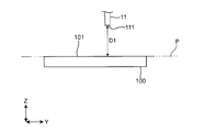
ディスペンサ10は、図1に示すように、ノズル11と変位センサ12とを有している。ノズル11は、図2および図3に示すように、塗布対象物100の塗布面101の外周縁に設けられた塗布領域102に鉛直方向Zから液体を吐出可能な吐出口111を有している。また、変位センサ12は、図3に示すように、吐出口111と塗布面101の塗布領域102との間の鉛直方向Zの距離Dを検出する。なお、図2および図3には、略矩形の塗布面101が、水平面XYに沿って配置されている板状の塗布対象物100を示している。
なお、ディスペンサ10は、例えば、吐出口111から吐出される液体として任意の粘度(Pa・s)の液体材料(例えば、粘度が0.001よりも小さいアルコールあるいは粘度が100を超えるクリーム半田)を用いることができるエアーパルス式ディスペンサである。このディスペンサ10では、ノズル11を鉛直方向に対して傾けると、吐出口111から吐出される液体の吐出量にバラツキが生じ易くなる。このバラツキは、液体の粘度が小さくなるに従って顕著になる。このため、ノズル11を鉛直方向Zに沿って配置して、塗布領域102に鉛直方向Zから液体を吐出可能に吐出口111を配置している。
駆動装置20は、例えば、ロボットであり、吐出口111から鉛直方向Zに液体を吐出可能な状態でディスペンサ10を保持して、水平方向X、Y(図2参照)および鉛直方向Z(図3参照)に移動可能に構成されている。
制御装置30は、演算等を行うCPU、ディスペンサ10および駆動装置20の制御に必要なプログラムあるいはデータを記憶しておくROMおよびRAMなどの記憶媒体と、外部装置(図示せず)との間で信号の入出力を行うインターフェース部とで構成されている。この制御装置30は、図1に示すように、ディスペンサ移動制御部31と、傾き検出部32と、塗布経路補正部33とを有している。なお、ディスペンサ移動制御部31、傾き検出部32および塗布経路補正部33の各部は、制御装置30のCPUが所定のプログラムを実行することにより実現される機能である。
ディスペンサ移動制御部31は、塗布対象物100毎に予め定められる塗布経路R1に沿ってディスペンサ10を移動させる。また、後述するように塗布経路補正部33により塗布経路R1が補正された場合、補正された塗布経路R2(図4参照)に沿ってディスペンサ10を移動させる。
傾き検出部32は、変位センサ12により検出された距離Dに基づいて、鉛直方向Zに交差する方向に延びる基準面P(この実施形態では、水平面)に対する塗布面101の傾きθ(図5参照)を検出する。詳しくは、傾き検出部32は、基準塗布対象物100の塗布面101の外周縁でかつ塗布経路R1上の予め設定された少なくとも3カ所(例えば、図2に示すA点、B点およびC点)で予め検出された基準距離D1と、塗布対象物100の塗布面101の外周縁でかつ塗布経路R1上の予め設定された少なくとも3カ所(すなわち、図4に示すA点、B点およびC点)で検出された距離D2とに基づいて、塗布面101上をX方向に延びる回転軸110まわりの傾きθを検出する。この実施形態では、図2および図3に示す塗布対象物100(すなわち、塗布面101が水平に配置された塗布対象物100)を基準塗布対象物100としている。なお、基準距離D1および距離D2は、鉛直方向Zにおいて、吐出口111が基準面Pに対して同じ位置にある状態で検出された距離Dである。また、基準面Pは、水平面に限らず、基準塗布対象物100の位置および姿勢などに応じて設定される。
塗布経路補正部33は、傾き検出部32により検出された塗布面101の傾きθに基づいて、塗布経路R1を補正する。例えば、塗布面101が回転軸110まわりに角度θ傾いている場合、図4および図5に示すように、液体の吐出方向である鉛直方向Zから見た塗布面101は、Y方向に△L×2だけ小さくなる。このため、塗布経路補正部33は、傾き検出部32により検出された塗布面101の傾きθに応じて塗布経路R1のY方向の長さを補正して、塗布経路R2を作成する。
また、塗布装置1は、塗布対象物100の位置および姿勢を検出する画像センサ40を備えている。この画像センサ40により検出された基準塗布対象物100の位置および姿勢に基づいて、制御装置30によって塗布経路R1が設定される。
次に、図6を参照して、塗布装置1を用いた塗布処理を説明する。なお、以下に説明する処理は、制御装置30が所定のプログラムを実行することで実施される。
図6に示すように、まず、ディスペンサ移動制御部31が、画像センサ40により検出された基準塗布対象物100の位置および姿勢から予め設定された塗布経路R1に沿って、ディスペンサ10を移動させる。そして、変位センサ12が、塗布面101の外周縁でかつ塗布経路R1上の予め設定された少なくとも3カ所で、吐出口111と塗布面101との間の鉛直方向Zにおける距離D2を検出する(ステップS1)。
距離D2が検出されると、傾き検出部32が、検出された距離D2と予め設定された基準距離D1とに基づいて、塗布面101の基準面Pに対する傾きθを検出する(ステップS2)。そして、制御装置30は、傾き検出部32により塗布面101の基準面Pに対する傾きθが検出されたか否かに基づいて、塗布面101が基準面Pに対して傾いているか否かを判定する(ステップS3)。
塗布面101が基準面Pに対して傾いていると判定されると、塗布経路補正部33が、検出された塗布面101の基準面Pに対する傾きθに基づいて、塗布経路R1を補正する(ステップS4)。そして、ディスペンサ移動制御部31が、補正された塗布経路R2に沿ってディスペンサ10を移動させる(ステップS5)。一方、塗布面101が基準面Pに対して傾いていないと判定されると、ディスペンサ移動制御部31は、塗布経路R1に沿ってディスペンサ10を移動させる(ステップS6)。
ステップS6およびステップS7において、ディスペンサ10が塗布経路R1、R2を移動しているとき、制御装置30は、ディスペンサ10を制御して、ノズル11の吐出口111から液体を塗布領域102に向かって吐出させる。そして、塗布領域102への液体の塗布が完了すると、塗布処理を終了する。
塗布装置1によれば、変位センサ12により検出された距離Dに基づいて、鉛直方向Zに交差する方向に延びる基準面Pに対する塗布面101の傾きθを検出し、検出された塗布面101の傾きθに基づいて、塗布経路R1を補正する。このような構成により、例えば、塗布対象物100が保持されておらず、塗布面101が基準面に対して傾いていたとしても、塗布面101の所定の位置(すなわち、塗布領域102)に液体を正確に塗布可能な塗布装置1を実現できる。
また、傾き検出部32は、塗布面101の外周縁でかつ塗布経路R1、R2上の少なくとも3カ所で検出された距離D1、D2に基づいて、塗布面101の傾きを検出する。このような構成により、塗布面101の基準面Pに対する傾きθをより正確に検出することができる。
なお、傾き検出部32により距離D1、D2が検出される塗布経路R1、R2上のカ所は、2カ所であってもよいし、塗布面101の外周縁でなくてもよい。
図7に示すように、塗布面101は、略矩形状に限らず、任意の形状であってもよい。また、塗布領域102は、塗布面101の外周縁に限らず、任意に設定することができる。
ディスペンサ移動制御部31は、塗布面101が基準面Pに対して傾いている場合、塗布面101が基準面Pに対して傾いていない場合とは異なる速度でディスペンサ10を移動させるように構成することができる。例えば、ノズル11から吐出される液体の吐出量が一定であり、基準面Pが水平面であり、塗布面101が水平面に対して傾いている場合、塗布面101が水平である場合よりも小さい速度でディスペンサ10を移動させる。詳しくは、塗布面101が水平である倍のディスペンサ10の移動速度をVとし、塗布面101が水平面に対して角度θ傾いているとすると、ディスペンサ移動制御部31は、VCosθの速度でディスペンサ10を移動させる。これにより、塗布対象物100の補正された塗布経路R2上に、基準塗布対象物100の塗布経路R1に沿って吐出された液体により形成される基準線と略同じ幅の線を形成することができる。
また、ディスペンサ移動制御部31は、傾き検出部32により検出された塗布面101の基準面Pに対する傾きが閾値以上のときに、塗布面101が基準面Pに対して傾いていない場合とは異なる速度でディスペンサ10を移動させるように構成することができる。これにより、塗布処理を簡単にして、塗布処理を行うときの制御装置30に対する負荷を軽減することができる。なお、閾値は、例えば、塗布面101が基準面Pに対して傾いていたとしても、塗布面101が基準面Pに対して傾いていない場合と略同じ塗布軌跡を描くことができるか否かの観点から決定される。
また、ディスペンサ移動制御部31は、塗布面101が水平面に対して角度θ傾いているとすると、鉛直方向Zにおいて塗布面101から基準距離D1/Cosθ離れた位置に吐出口111が位置するように、補正された塗布経路R2に沿ってディスペンサ10移動させるように構成することができる。これにより、塗布対象物100の塗布経路R2上に、基準塗布対象物100の塗布経路R1上に吐出された液体により形成される基準線と略同じ幅の線を形成することができる。
塗布装置1は、基準面Pに対する塗布面101の傾きθに対するずれのみならず、水平面上の回転ずれ、および、鉛直方向のずれを補正することができるように構成することができる。なお、水平面上の回転ずれ、および、鉛直方向のずれについては、例えば、画像センサ40により検出された基準塗布対象物100の位置および姿勢を基準位置および基準姿勢として設定しておき、この基準位置および基準姿勢と、画像センサ40により検出された塗布対象物100の位置および姿勢とに基づいて検出することができる。
以上、図面を参照して本開示における種々の実施形態を詳細に説明したが、最後に、本開示の種々の態様について説明する。なお、以下の説明では、一例として、参照符号も添えて記載する。
本開示の第1態様の塗布装置1は、
塗布面101を有する塗布対象物100の前記塗布面101に設けられた塗布領域102に鉛直方向Zから液体を吐出可能な吐出口111と、前記吐出口111と前記塗布領域102との間の鉛直方向Zの距離D1、D2を検出する変位センサ12とを有するディスペンサ10と、
前記ディスペンサ10を駆動する駆動装置20と、
前記駆動装置20を制御して、予め定められている塗布経路R1に沿って前記ディスペンサ10を移動させるディスペンサ移動制御部31と、
前記変位センサ12により検出された前記距離D1、D2に基づいて、鉛直方向Zに交差する方向に延びる基準面Pに対する前記塗布面101の傾きを検出する傾き検出部32と、
前記傾き検出部32により検出された前記塗布面101の傾きに基づいて、前記塗布経路R1を補正する塗布経路補正部33と
を備え、
前記ディスペンサ移動制御部31は、前記塗布経路補正部33により前記塗布経路R1が補正された場合、補正された前記塗布経路R2に沿って前記ディスペンサ10を移動させる。
第1態様の塗布装置1によれば、変位センサ12により検出された距離Dに基づいて、鉛直方向Zに交差する方向に延びる基準面Pに対する塗布面101の傾きθを検出し、検出された塗布面101の傾きθに基づいて、塗布経路R1を補正する。このような構成により、例えば、塗布対象物100が保持されておらず、塗布面101が基準面に対して傾いていたとしても、塗布面101の所定の位置(すなわち、塗布領域102)に液体を正確に塗布可能な塗布装置1を実現できる。
本開示の第2態様の塗布装置1は、
前記傾き検出部32は、
前記塗布面101の外周縁かつ前記塗布経路R1、R2上の少なくとも3カ所で検出された前記距離D1、D2に基づいて、前記塗布面101の傾きを検出する。
前記傾き検出部32は、
前記塗布面101の外周縁かつ前記塗布経路R1、R2上の少なくとも3カ所で検出された前記距離D1、D2に基づいて、前記塗布面101の傾きを検出する。
第2態様の塗布装置1によれば、塗布面101の基準面Pに対する傾きθをより正確に検出することができる。
本開示の第3態様の塗布装置1は、
前記ディスペンサ移動制御部31は、
前記塗布面101が前記基準面Pに対して傾いている場合、前記塗布面101が前記基準面Pに対して傾いていない場合とは異なる速度で前記ディスペンサ10を移動させる。
前記ディスペンサ移動制御部31は、
前記塗布面101が前記基準面Pに対して傾いている場合、前記塗布面101が前記基準面Pに対して傾いていない場合とは異なる速度で前記ディスペンサ10を移動させる。
第3態様の塗布装置1によれば、塗布対象物100の補正された塗布経路R2上に、基準塗布対象物100の塗布経路R1に沿って吐出された液体により形成される基準線と略同じ幅の線を形成することができる。
本開示の第4態様の塗布装置1は、
前記傾き検出部32により検出された前記塗布面101の前記基準面Pに対する傾きが閾値以上のときに、前記塗布面101が前記基準面Pに対して傾いていない場合とは異なる速度で前記ディスペンサ10を移動させる。
前記傾き検出部32により検出された前記塗布面101の前記基準面Pに対する傾きが閾値以上のときに、前記塗布面101が前記基準面Pに対して傾いていない場合とは異なる速度で前記ディスペンサ10を移動させる。
第4態様の塗布装置1によれば、塗布処理を簡単にして、塗布処理を行うときの制御装置30に対する負荷を軽減することができる。
本開示の第5態様の塗布装置1は、
前記ディスペンサ移動制御部31は、
前記基準面Pが水平面であり、前記塗布面101が水平面に対して傾いている場合、前記塗布面101が水平である場合よりも小さい速度で前記ディスペンサ10を移動させる。
前記ディスペンサ移動制御部31は、
前記基準面Pが水平面であり、前記塗布面101が水平面に対して傾いている場合、前記塗布面101が水平である場合よりも小さい速度で前記ディスペンサ10を移動させる。
第5態様の塗布装置1によれば、塗布対象物100の補正された塗布経路R2上に、基準塗布対象物100の塗布経路R1に沿って吐出された液体により形成される基準線と略同じ幅の線を形成することができる。
なお、前記様々な実施形態または変形例のうちの任意の実施形態または変形例を適宜組み合わせることにより、それぞれの有する効果を奏するようにすることができる。また、実施形態同士の組み合わせまたは実施例同士の組み合わせまたは実施形態と実施例との組み合わせが可能であると共に、異なる実施形態または実施例の中の特徴同士の組み合わせも可能である。
本開示は、添付図面を参照しながら好ましい実施形態に関連して充分に記載されているが、この技術の熟練した人々にとっては種々の変形や修正は明白である。そのような変形や修正は、添付した請求の範囲による本開示の範囲から外れない限りにおいて、その中に含まれると理解されるべきである。
本開示の塗布装置は、例えば、ウインドガラスへのシーラーの塗布に用いることができる。
1 塗布装置
10 ディスペンサ
11 ノズル
111 吐出口
12 変位センサ
20 駆動装置
30 制御装置
31 ディスペンサ移動制御部
32 傾き検出部
33 塗布経路補正部
40 画像センサ
100 塗布対象物
101 塗布面
102 塗布領域
110 回転軸
R1、R2 塗布経路
P 基準面
10 ディスペンサ
11 ノズル
111 吐出口
12 変位センサ
20 駆動装置
30 制御装置
31 ディスペンサ移動制御部
32 傾き検出部
33 塗布経路補正部
40 画像センサ
100 塗布対象物
101 塗布面
102 塗布領域
110 回転軸
R1、R2 塗布経路
P 基準面
Claims (5)
- 塗布面を有する塗布対象物の前記塗布面に設けられた塗布領域に鉛直方向から液体を吐出可能な吐出口と、前記吐出口と前記塗布領域との間の鉛直方向の距離を検出する変位センサとを有するディスペンサと、
前記ディスペンサを駆動する駆動装置と、
前記駆動装置を制御して、予め定められている塗布経路に沿って前記ディスペンサを移動させるディスペンサ移動制御部と、
前記変位センサにより検出された前記距離に基づいて、鉛直方向に交差する方向に延びる基準面に対する前記塗布面の傾きを検出する傾き検出部と、
前記傾き検出部により検出された前記塗布面の傾きに基づいて、前記塗布経路を補正する塗布経路補正部と
を備え、
前記ディスペンサ移動制御部は、前記塗布経路補正部により前記塗布経路が補正された場合、補正された前記塗布経路に沿って前記ディスペンサを移動させる、塗布装置。 - 前記傾き検出部は、
前記塗布面の外周縁かつ前記塗布経路上の少なくとも3カ所で検出された前記距離に基づいて、前記塗布面の傾きを検出する、請求項1の塗布装置。 - 前記ディスペンサ移動制御部は、
前記塗布面が前記基準面に対して傾いている場合、前記塗布面が前記基準面に対して傾いていない場合とは異なる速度で前記ディスペンサを移動させる、請求項1または2の塗布装置。 - 前記傾き検出部により検出された前記塗布面の前記基準面に対する傾きが閾値以上のときに、前記塗布面が前記基準面に対して傾いていない場合とは異なる速度で前記ディスペンサを移動させる、請求項3の塗布装置。
- 前記ディスペンサ移動制御部は、
前記基準面が水平面であり、前記塗布面が水平面に対して傾いている場合、前記塗布面が水平である場合よりも小さい速度で前記ディスペンサを移動させる、請求項3または4の塗布装置。
Priority Applications (4)
| Application Number | Priority Date | Filing Date | Title |
|---|---|---|---|
| EP19883256.0A EP3858493A4 (en) | 2018-11-07 | 2019-10-18 | Coating apparatus |
| KR1020217011636A KR102467828B1 (ko) | 2018-11-07 | 2019-10-18 | 도포 장치 |
| US17/291,683 US11596971B2 (en) | 2018-11-07 | 2019-10-18 | Coating apparatus |
| CN201980070738.6A CN112912182B (zh) | 2018-11-07 | 2019-10-18 | 涂布装置 |
Applications Claiming Priority (2)
| Application Number | Priority Date | Filing Date | Title |
|---|---|---|---|
| JP2018-209956 | 2018-11-07 | ||
| JP2018209956A JP6988767B2 (ja) | 2018-11-07 | 2018-11-07 | 塗布装置 |
Publications (1)
| Publication Number | Publication Date |
|---|---|
| WO2020095653A1 true WO2020095653A1 (ja) | 2020-05-14 |
Family
ID=70611011
Family Applications (1)
| Application Number | Title | Priority Date | Filing Date |
|---|---|---|---|
| PCT/JP2019/041082 Ceased WO2020095653A1 (ja) | 2018-11-07 | 2019-10-18 | 塗布装置 |
Country Status (6)
| Country | Link |
|---|---|
| US (1) | US11596971B2 (ja) |
| EP (1) | EP3858493A4 (ja) |
| JP (1) | JP6988767B2 (ja) |
| KR (1) | KR102467828B1 (ja) |
| CN (1) | CN112912182B (ja) |
| WO (1) | WO2020095653A1 (ja) |
Families Citing this family (1)
| Publication number | Priority date | Publication date | Assignee | Title |
|---|---|---|---|---|
| CN115722420B (zh) * | 2022-12-19 | 2023-07-14 | 宁波博信电器有限公司 | 一种仪表盘上胶加工方法、系统、存储介质及智能终端 |
Citations (9)
| Publication number | Priority date | Publication date | Assignee | Title |
|---|---|---|---|---|
| JPH05108131A (ja) * | 1991-10-16 | 1993-04-30 | Toshiba Corp | ロボツトの教示装置 |
| JPH10211458A (ja) * | 1997-01-28 | 1998-08-11 | Honda Motor Co Ltd | ウインドガラスへのシーラー塗布方法および装置 |
| JP2000244107A (ja) * | 1999-02-24 | 2000-09-08 | Nec Corp | 吐出量制御機能付きディスペンサ及びクリーム半田の塗布方法 |
| JP2001000905A (ja) * | 1999-06-22 | 2001-01-09 | Honda Motor Co Ltd | シーラー剤塗布方法及びシーラー剤塗布装置 |
| JP2003039000A (ja) * | 2001-07-27 | 2003-02-12 | Hitachi Industries Co Ltd | ペースト塗布機 |
| JP2004243215A (ja) | 2003-02-13 | 2004-09-02 | Suzuki Motor Corp | シーラー塗布装置のロボットティーチング方法及びシーラー塗布装置 |
| JP2008023471A (ja) * | 2006-07-24 | 2008-02-07 | Hitachi Plant Technologies Ltd | ペースト塗布機及びペースト塗布方法 |
| JP2010110700A (ja) * | 2008-11-06 | 2010-05-20 | Ulvac Japan Ltd | インクジェット塗布装置、平行度調整装置 |
| JP3177944U (ja) * | 2012-06-13 | 2012-08-23 | 大東工業株式会社 | ソーラーパネル用保護ガラス板の塗布装置 |
Family Cites Families (11)
| Publication number | Priority date | Publication date | Assignee | Title |
|---|---|---|---|---|
| DE1611724B1 (de) * | 1967-08-16 | 1971-03-18 | Henkel & Cie Gmbh | Steuerungsvorrichtung fuer das Verschliessorgan eines Klebstoffauftragsgeraetes |
| NL6909118A (ja) * | 1969-06-13 | 1970-12-15 | ||
| US5984470A (en) * | 1995-04-20 | 1999-11-16 | Canon Kabushiki Kaisha | Apparatus for producing color filter with alignment error detection |
| US6866881B2 (en) * | 1999-02-19 | 2005-03-15 | Speedline Technologies, Inc. | Dispensing system and method |
| KR100794714B1 (ko) * | 2004-08-03 | 2008-01-15 | 현대중공업 주식회사 | 로봇의 연속 용접선 추종 제어 시스템 및 그 제어방법 |
| CA2705764C (en) | 2007-11-14 | 2016-08-02 | Biosensors International Group, Ltd. | Automated stent coating apparatus and method |
| JP5705661B2 (ja) * | 2011-06-13 | 2015-04-22 | 株式会社オーテックエレクトロニクス | 液体定量吐出装置及び液体定量吐出方法 |
| JP5475059B2 (ja) * | 2012-06-13 | 2014-04-16 | キヤノンマシナリー株式会社 | 塗布装置 |
| US9707584B2 (en) | 2014-07-09 | 2017-07-18 | Nordson Corporation | Dual applicator fluid dispensing methods and systems |
| DE102014116830A1 (de) * | 2014-11-18 | 2016-05-19 | Intec Bielenberg Gmbh & Co Kg | Vorrichtung zum Dämmmattenauftrag |
| JP6590667B2 (ja) * | 2015-11-30 | 2019-10-16 | キヤノン株式会社 | インプリント装置、インプリント方法、および物品の製造方法 |
-
2018
- 2018-11-07 JP JP2018209956A patent/JP6988767B2/ja active Active
-
2019
- 2019-10-18 EP EP19883256.0A patent/EP3858493A4/en not_active Withdrawn
- 2019-10-18 CN CN201980070738.6A patent/CN112912182B/zh active Active
- 2019-10-18 KR KR1020217011636A patent/KR102467828B1/ko active Active
- 2019-10-18 WO PCT/JP2019/041082 patent/WO2020095653A1/ja not_active Ceased
- 2019-10-18 US US17/291,683 patent/US11596971B2/en active Active
Patent Citations (9)
| Publication number | Priority date | Publication date | Assignee | Title |
|---|---|---|---|---|
| JPH05108131A (ja) * | 1991-10-16 | 1993-04-30 | Toshiba Corp | ロボツトの教示装置 |
| JPH10211458A (ja) * | 1997-01-28 | 1998-08-11 | Honda Motor Co Ltd | ウインドガラスへのシーラー塗布方法および装置 |
| JP2000244107A (ja) * | 1999-02-24 | 2000-09-08 | Nec Corp | 吐出量制御機能付きディスペンサ及びクリーム半田の塗布方法 |
| JP2001000905A (ja) * | 1999-06-22 | 2001-01-09 | Honda Motor Co Ltd | シーラー剤塗布方法及びシーラー剤塗布装置 |
| JP2003039000A (ja) * | 2001-07-27 | 2003-02-12 | Hitachi Industries Co Ltd | ペースト塗布機 |
| JP2004243215A (ja) | 2003-02-13 | 2004-09-02 | Suzuki Motor Corp | シーラー塗布装置のロボットティーチング方法及びシーラー塗布装置 |
| JP2008023471A (ja) * | 2006-07-24 | 2008-02-07 | Hitachi Plant Technologies Ltd | ペースト塗布機及びペースト塗布方法 |
| JP2010110700A (ja) * | 2008-11-06 | 2010-05-20 | Ulvac Japan Ltd | インクジェット塗布装置、平行度調整装置 |
| JP3177944U (ja) * | 2012-06-13 | 2012-08-23 | 大東工業株式会社 | ソーラーパネル用保護ガラス板の塗布装置 |
Non-Patent Citations (1)
| Title |
|---|
| See also references of EP3858493A4 |
Also Published As
| Publication number | Publication date |
|---|---|
| JP2020075213A (ja) | 2020-05-21 |
| EP3858493A1 (en) | 2021-08-04 |
| KR102467828B1 (ko) | 2022-11-18 |
| JP6988767B2 (ja) | 2022-01-05 |
| CN112912182B (zh) | 2023-05-02 |
| US11596971B2 (en) | 2023-03-07 |
| EP3858493A4 (en) | 2022-08-03 |
| CN112912182A (zh) | 2021-06-04 |
| US20220001416A1 (en) | 2022-01-06 |
| KR20210063372A (ko) | 2021-06-01 |
Similar Documents
| Publication | Publication Date | Title |
|---|---|---|
| JP6884109B2 (ja) | 基板搬送ロボットおよびその運転方法 | |
| US12458992B2 (en) | Painting robot and painting method using painting robot | |
| US20150285721A1 (en) | Welding inspection robot system | |
| CN105329642B (zh) | 基板位置偏移检测及校正方法和基板搬运系统的控制方法 | |
| US11161141B2 (en) | Coating device configured to apply a coating agent to an object and detect a shape of the object after the application of the coating agent to the object | |
| US12472528B2 (en) | Apparatus for coating an automobile, method for coating an automobile, and computer program product | |
| WO2020095653A1 (ja) | 塗布装置 | |
| US20190283258A1 (en) | Robot system and control method of robot | |
| US20190283256A1 (en) | Robot system and control method of robot | |
| TWI490046B (zh) | Slurry coating apparatus and slurry coating method | |
| US11541552B2 (en) | Control device controlling robot and robot system | |
| JP6243278B2 (ja) | 塗布液塗布装置及び方法 | |
| JP4940806B2 (ja) | ペースト塗布機及びペースト塗布方法 | |
| CN101954329B (zh) | 糊剂涂敷装置 | |
| KR20240110643A (ko) | 기판 반송 로봇의 제어 장치 및 관절 모터의 제어 방법 | |
| KR20160105890A (ko) | 텐션 제어 장치 | |
| JP4739426B2 (ja) | インクジェットヘッド取付け位置調整方法、及びインクジェット装置のヘッド位置制御方法 | |
| KR20170128824A (ko) | 디스펜싱 방법 | |
| WO2014069277A1 (ja) | ストライプ塗布方法およびストライプ塗布装置 | |
| KR100555717B1 (ko) | 산업용 로봇의 원점좌표 오차보정장치 및 방법 | |
| KR20000002415U (ko) | 액정 패널의 실리콘 도포 장치 | |
| JP5400082B2 (ja) | 基板搬送装置及び基板搬送方法 | |
| KR20170004365A (ko) | 보정롤러를 포함하는 골판지 배출유닛 | |
| CN110349856B (zh) | 湿式蚀刻方法及装置 | |
| JPH05185005A (ja) | ペースト塗布機 |
Legal Events
| Date | Code | Title | Description |
|---|---|---|---|
| 121 | Ep: the epo has been informed by wipo that ep was designated in this application |
Ref document number: 19883256 Country of ref document: EP Kind code of ref document: A1 |
|
| ENP | Entry into the national phase |
Ref document number: 20217011636 Country of ref document: KR Kind code of ref document: A |
|
| NENP | Non-entry into the national phase |
Ref country code: DE |
|
| ENP | Entry into the national phase |
Ref document number: 2019883256 Country of ref document: EP Effective date: 20210428 |