WO2020095923A1 - Dispositif d'affichage destiné à un véhicule et système d'affichage destiné à un véhicule - Google Patents
Dispositif d'affichage destiné à un véhicule et système d'affichage destiné à un véhicule Download PDFInfo
- Publication number
- WO2020095923A1 WO2020095923A1 PCT/JP2019/043389 JP2019043389W WO2020095923A1 WO 2020095923 A1 WO2020095923 A1 WO 2020095923A1 JP 2019043389 W JP2019043389 W JP 2019043389W WO 2020095923 A1 WO2020095923 A1 WO 2020095923A1
- Authority
- WO
- WIPO (PCT)
- Prior art keywords
- display
- vehicle
- curved portion
- display device
- virtual image
- Prior art date
- Legal status (The legal status is an assumption and is not a legal conclusion. Google has not performed a legal analysis and makes no representation as to the accuracy of the status listed.)
- Ceased
Links
Images






Classifications
-
- B—PERFORMING OPERATIONS; TRANSPORTING
- B60—VEHICLES IN GENERAL
- B60K—ARRANGEMENT OR MOUNTING OF PROPULSION UNITS OR OF TRANSMISSIONS IN VEHICLES; ARRANGEMENT OR MOUNTING OF PLURAL DIVERSE PRIME-MOVERS IN VEHICLES; AUXILIARY DRIVES FOR VEHICLES; INSTRUMENTATION OR DASHBOARDS FOR VEHICLES; ARRANGEMENTS IN CONNECTION WITH COOLING, AIR INTAKE, GAS EXHAUST OR FUEL SUPPLY OF PROPULSION UNITS IN VEHICLES
- B60K35/00—Instruments specially adapted for vehicles; Arrangement of instruments in or on vehicles
- B60K35/10—Input arrangements, i.e. from user to vehicle, associated with vehicle functions or specially adapted therefor
-
- B—PERFORMING OPERATIONS; TRANSPORTING
- B60—VEHICLES IN GENERAL
- B60K—ARRANGEMENT OR MOUNTING OF PROPULSION UNITS OR OF TRANSMISSIONS IN VEHICLES; ARRANGEMENT OR MOUNTING OF PLURAL DIVERSE PRIME-MOVERS IN VEHICLES; AUXILIARY DRIVES FOR VEHICLES; INSTRUMENTATION OR DASHBOARDS FOR VEHICLES; ARRANGEMENTS IN CONNECTION WITH COOLING, AIR INTAKE, GAS EXHAUST OR FUEL SUPPLY OF PROPULSION UNITS IN VEHICLES
- B60K35/00—Instruments specially adapted for vehicles; Arrangement of instruments in or on vehicles
- B60K35/20—Output arrangements, i.e. from vehicle to user, associated with vehicle functions or specially adapted therefor
- B60K35/21—Output arrangements, i.e. from vehicle to user, associated with vehicle functions or specially adapted therefor using visual output, e.g. blinking lights or matrix displays
- B60K35/22—Display screens
-
- B—PERFORMING OPERATIONS; TRANSPORTING
- B60—VEHICLES IN GENERAL
- B60K—ARRANGEMENT OR MOUNTING OF PROPULSION UNITS OR OF TRANSMISSIONS IN VEHICLES; ARRANGEMENT OR MOUNTING OF PLURAL DIVERSE PRIME-MOVERS IN VEHICLES; AUXILIARY DRIVES FOR VEHICLES; INSTRUMENTATION OR DASHBOARDS FOR VEHICLES; ARRANGEMENTS IN CONNECTION WITH COOLING, AIR INTAKE, GAS EXHAUST OR FUEL SUPPLY OF PROPULSION UNITS IN VEHICLES
- B60K35/00—Instruments specially adapted for vehicles; Arrangement of instruments in or on vehicles
- B60K35/20—Output arrangements, i.e. from vehicle to user, associated with vehicle functions or specially adapted therefor
- B60K35/21—Output arrangements, i.e. from vehicle to user, associated with vehicle functions or specially adapted therefor using visual output, e.g. blinking lights or matrix displays
- B60K35/23—Head-up displays [HUD]
- B60K35/231—Head-up displays [HUD] characterised by their arrangement or structure for integration into vehicles
-
- B—PERFORMING OPERATIONS; TRANSPORTING
- B60—VEHICLES IN GENERAL
- B60K—ARRANGEMENT OR MOUNTING OF PROPULSION UNITS OR OF TRANSMISSIONS IN VEHICLES; ARRANGEMENT OR MOUNTING OF PLURAL DIVERSE PRIME-MOVERS IN VEHICLES; AUXILIARY DRIVES FOR VEHICLES; INSTRUMENTATION OR DASHBOARDS FOR VEHICLES; ARRANGEMENTS IN CONNECTION WITH COOLING, AIR INTAKE, GAS EXHAUST OR FUEL SUPPLY OF PROPULSION UNITS IN VEHICLES
- B60K35/00—Instruments specially adapted for vehicles; Arrangement of instruments in or on vehicles
- B60K35/20—Output arrangements, i.e. from vehicle to user, associated with vehicle functions or specially adapted therefor
- B60K35/29—Instruments characterised by the way in which information is handled, e.g. showing information on plural displays or prioritising information according to driving conditions
-
- B—PERFORMING OPERATIONS; TRANSPORTING
- B60—VEHICLES IN GENERAL
- B60K—ARRANGEMENT OR MOUNTING OF PROPULSION UNITS OR OF TRANSMISSIONS IN VEHICLES; ARRANGEMENT OR MOUNTING OF PLURAL DIVERSE PRIME-MOVERS IN VEHICLES; AUXILIARY DRIVES FOR VEHICLES; INSTRUMENTATION OR DASHBOARDS FOR VEHICLES; ARRANGEMENTS IN CONNECTION WITH COOLING, AIR INTAKE, GAS EXHAUST OR FUEL SUPPLY OF PROPULSION UNITS IN VEHICLES
- B60K35/00—Instruments specially adapted for vehicles; Arrangement of instruments in or on vehicles
- B60K35/80—Arrangements for controlling instruments
Definitions
- the present disclosure relates to a vehicle display device and a vehicle display system.
- a vehicle display device configured to be installed in a vehicle.
- the display surface covered with the exposed translucent plate in order to realize a pseudo curved surface is installed upright.
- the exposed translucent plate is curved in a concave shape.
- the present disclosure aims to provide a display device for a vehicle and a display system for a vehicle, which makes it easy to grasp the display content by expressing a bird's-eye view feeling to the user.
- a vehicular display device configured to be installed in a vehicle has a plurality of bending portions that are curved with a curvature provided in a front-rear direction from a front side to a rear side of the vehicle, The display surface is formed so that a real image can be displayed upward.
- the plurality of curved portions have a concave curved portion that is curved in a concave shape and a convex curved portion that is curved in a convex shape at positions that are displaced from each other in the depth direction.
- the convex curved portion is arranged on the most front side.
- the concave curved portion and the convex curved portion are provided on the display surface formed so as to be able to display the real image upward.
- the user can visually recognize the display on the display surface having a feeling of height as if looking down.
- the concave curved portion and the convex curved portion which are arranged on the innermost side, are the convex curved portions, so that the rear portion of the display surface is prevented from standing up, and the horizontal portion is suppressed. A sense of spreading in the direction can be generated.
- a vehicular display system configured to be mounted on a vehicle projects display light that can be imaged as a virtual image onto a virtual image forming unit installed in the vehicle.
- a head-up display device and a display surface that has a plurality of curved portions that are curved with a curvature provided in the front-back direction from the rear side to the front side of the vehicle and that displays a real image upward.
- the curving portion has a concave curving portion curving in a concave shape and a convex curving portion curving in a convex shape at portions displaced from each other in the front-rear direction.
- the convex curved portion is arranged on the most front side.
- the frontmost end of the display surface is arranged with respect to the virtual image forming unit so that the real image is displayed behind the virtual image.
- the concave curved portion and the convex curved portion are provided on the display surface formed so as to be able to display the real image upward.
- the user can visually recognize the display on the display surface having a feeling of height as if looking down.
- the concave curved portion and the convex curved portion which are arranged on the innermost side, are the convex curved portions, so that the rear portion of the display surface is prevented from standing up, and the horizontal portion is suppressed. A sense of spreading in the direction can be generated.
- a real image is formed using the virtual image forming unit based on the positional relationship between the innermost end of the display surface and the virtual image forming unit onto which the display light of the head-up display device is projected. Displaying on the front side of the virtual image enables continuous display between the real image and the virtual image. That is, the sense of expansion of the real image display in the depth direction becomes remarkable.
- FIG. 3 is a perspective view showing a state in which the vehicle display system according to the first embodiment is mounted on a vehicle
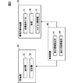
- 1 is a block diagram showing a schematic configuration of a vehicle display system according to a first embodiment
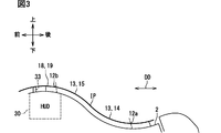
- It is a sectional view showing a section including a depth direction and a vertical surface of a display system for vehicles in a 1st embodiment
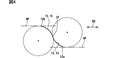
- It is a schematic diagram for explaining the curved form of the display surface
- It is a diagram for explaining a curved form of the display surface and a plurality of display regions
- It is a figure which shows the example of a display in 1st Embodiment
- It is a flow chart by the display system for vehicles of a 1st embodiment
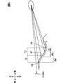
- It is a figure corresponding to FIG.
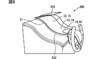
- FIG. 6 is a perspective view showing a state in which the vehicle display system according to the second embodiment is mounted on a vehicle, It is a figure which shows the example of a display by 2nd Embodiment, It is a figure which shows the other display example by 2nd Embodiment, It is a figure which shows the other display example by 2nd Embodiment, It is a figure which shows the other display example by 2nd Embodiment, It is a figure which shows the other display example by 2nd Embodiment, It is a figure which shows the other display example by 2nd Embodiment, It is a figure which shows the other example of a display by 2nd Embodiment.
- the vehicle display device 10 is configured to be installed on the instrument panel 2 of the vehicle 1, as shown in FIG. 1.
- the vehicular display device 10 constitutes a vehicular display system 100 together with a head-up display device (hereinafter, HUD device) 30, a control device 40, and the like.
- the vehicle display device 10 is installed in the instrument panel 2 at a driver's seat facing portion that faces the driver's seat on which the driver as the user of the vehicle display system 100 is seated.
- the directions of up, down, front, rear, left and right are defined with reference to the vehicle 1 on the road surface on which the horizontal plane HP is maintained.
- the vehicle 1 when it is necessary to distinguish the vehicle 1 from other vehicles, it may be referred to as “own vehicle” for convenience.
- the windshield 3 of the vehicle 1 is arranged above the instrument panel 2.
- the windshield 3 is formed of, for example, glass or synthetic resin in a translucent plate shape, and is arranged above the instrument panel 2.
- the windshield 3 is arranged so as to be inclined from the instrument panel 2 as it goes from the front to the rear.
- the vehicle display device 10 is a so-called graphic meter, and has an image display panel 11, a frame portion 18, and an ambient lighting portion 21.
- the image display panel 11 is a curved panel formed in a thin plate shape. More specifically, the image display panel 11 is an EL panel in which pixels capable of self-luminous emission are two-dimensionally arranged by using electroluminescence and have a display surface 12 having a rectangular outline. For this self-emission, organic electroluminescence or inorganic electroluminescence can be used.
- the display surface 12 is formed so as to be exposed on the upper portion of the instrument panel 2 so that the real image RI can be displayed upward.
- the display surface 12 is formed into a curved surface like a ski jumping stand.
- the depth direction DD When the direction from the front side to the back side with respect to the seat on which the driver sits is defined as the depth direction DD, as shown in FIG. 3, the rectangular display surface 12 has its longitudinal direction aligned with the depth direction DD. Are arranged.
- the depth direction DD can be defined along the front-rear direction of the vehicle 1.
- the display surface 12 has a plurality of bending portions 13 that are curved with a curvature provided in the depth direction DD.
- the curved portion 13 is curved with a non-zero curvature set on a cross section including the depth direction DD and the vertical plane.
- one concave bending portion 14 and one convex bending portion 15 are provided on the display surface 12 at positions deviated from each other in the depth direction DD. ..
- the concave curved portion 14 is arranged on the front side of the convex curved portion 15.
- the concave curved portion 14 is curved in a concave shape, and more specifically, is formed in a cylindrical surface shape in which a generatrix extends in a left-right direction orthogonal to the depth direction DD.
- the convex curved portion 15 is arranged farther back than the concave curved portion 14.
- the convex curved portion 15 is curved in a convex shape, and more specifically, is formed in a cylindrical surface shape in which a generatrix extends in the left-right direction.
- the concave curved portion 14 is arranged at the innermost side, not the convex curved portion 15. Further, as shown in FIG. 4, in the present embodiment, the curvature of the concave curved portion 14 and the curvature of the convex curved portion 15 are substantially the same.
- the display surface 12 is not provided with a flat portion. That is, the display surface 12 is entirely occupied by the one concave curved portion 14 and the one convex curved portion 15, and all the portions of the display surface 12 are curved. That is, the entire display surface 12 is S-shaped.
- the concave curved portion 14 reaches the end portion 12a on the most front side of the display surface 12.
- the concave curved portion 14 is formed so that the concave curved portion 14 is closer to the horizontal plane HP as it goes from the rear side portion having an inclined state facing the front side to the front side portion.
- the end 12a on the most front side of the display surface 12 does not reach the horizontal state and a slight gradient is left, so that an inclined state slightly facing the front side is maintained. There is.
- the convex curved portion 15 reaches the farthest end 12b of the display surface 12.
- the convex curved portion 15 is formed so that the convex curved portion 15 is closer to the horizontal plane HP as it goes from the front side portion having an inclined state facing the front side to the rear side portion.
- the end 12b on the farthest side of the display surface 12 does not reach the horizontal state and has a slight gradient, so that the inclined state of slightly facing the front side is maintained. There is.
- the concave curved portion 14 and the convex curved portion 15 are directly and smoothly connected to each other via an inflection point IP whose bending direction changes.
- the term “smooth” as used herein means that the curvature and the first derivative of the curvature have continuity.
- the inflection point IP is expressed as a “point” for convenience, it is strictly set in a “line” shape because the display surface 12 has a width in the left-right direction. It can be broadly understood to include.
- the gradient of the display surface 12 at the inflection point IP is the maximum of the gradients of the respective parts on the display surface 12. Even at the inflection point IP, the display surface 12 does not face directly to the side, but has an upward component and is maintained in an inclined state.
- the slope of the display surface 12 becomes gradually smaller as it goes from the inflection point IP to the near side or the far side, and the shape approaches the horizontal plane HP as described above. In this way, the display surface 12 has a height difference that rises upward from the front side to the back side.
- a liquid crystal panel other than the EL panel may be adopted as long as the curved display surface 12 can be realized.
- the frame 18 is made of, for example, a synthetic resin in a dark color (for example, black), and has a frame shape surrounding the entire circumference of the display surface 12 of the image display panel 11.
- the frame portion 18 has a non-display stretching surface 19 that extends so as to be continuous with the display surface 12 from the farthest end 12 b of the display surface 12 to the further back side.
- the non-display stretched surface 19 is non-displayable and is formed in a flat shape.
- the ambient lighting unit 21 shown in FIG. 1 is provided on the side wall of the device 10 that faces the left-right direction. In other words, the ambient lighting sections 21 are provided on both sides of the display surface 12 in between.
- the ambient illumination unit 21 is provided, for example, by arranging a plurality of light emitting diode elements in the depth direction DD, and illuminates the periphery of the display surface 12.
- the HUD device 30 is configured to be installed on the instrument panel 2 of the vehicle 1, as shown in FIGS.
- the HUD device 30 projects the display light toward the virtual image forming unit 3a formed in the windshield 3 of the vehicle 1 in a planar shape or a concave shape. That is, the driver sitting on the seat can perceive the display light reflected by the virtual image forming unit 3a as the formed virtual image VI.
- the HUD device 30 includes a display unit 31, a reflecting mirror 32, and the like.
- the display unit 31, the reflecting mirror 32, and the like are housed inside a housing having a light shielding property.
- the display 31 displays an image and emits the display light.
- a liquid crystal display using a backlight a display using an EL panel that self-luminesces using electroluminescence, a display using a laser scanner, and a DLP (Digital Micromirror Device) DLP are used. (Digital Light Processing; registered trademark) type display and the like can be adopted.
- the reflecting mirror 32 is formed, for example, by depositing a metal film such as aluminum on the surface of synthetic resin or glass.
- the reflecting mirror 32 has a concave or flat reflecting surface.
- the reflecting mirror 32 reflects the display light emitted from the display 31 toward the virtual image forming unit 3a by the reflecting surface.
- a window 33 is provided on the upper surface of the housing and the upper surface of the instrument panel 2, and the display light reflected by the reflecting mirror 32 passes through the window 33 to the virtual image forming unit 3a.
- the window portion 33 may be mechanically opened by forming an opening hole, or may be optically opened by being blocked by a dust-proof sheet having a light-transmitting property or a semi-light-transmitting property.
- the window 33 is provided by, for example, forming a part of the non-display stretched surface 19 with a dust-proof sheet having a semi-translucent property by coloring in a smoke tone.
- the virtual image forming unit 3a can be set in the vicinity of the end 12b of the display surface 12, and the horizontal position of the virtual image forming unit 3a and the horizontal position of the display surface 12 can be easily adjusted. Can be adjusted to Then, the real image RI displayed on the display surface 12 is displayed in front of the virtual image VI.
- the control device 40 is a so-called computer, and is mainly composed of an electronic circuit including at least one processor, a memory device, and an input / output interface.
- the processor is an arithmetic circuit that executes a computer program stored in the memory device.
- the memory device is a storage medium that is provided by, for example, a semiconductor memory and that temporarily stores computer programs and data that can be read by a processor.
- the control device 40 is communicably connected to the image display panel 11 of the vehicular display device 10 and the display 31 of the HUD device 30, and the real image RI and the display 31 displayed on the display surface 12 by the image display panel 11 are displayed. To control the virtual image VI displayed.
- the control device 40 is configured to be able to acquire various information from the vehicle 1 by inputting an electrical signal using communication.
- the control device 40 has a display area setting unit 41 and a display content allocation unit 42 as functional blocks.
- the display area setting unit 41 sets a plurality of display areas DA1, DA2, DA3 for the real image RI displayed on the display surface 12 and the virtual image VI displayed via the virtual image forming unit 3a.
- the plurality of display areas DA1, DA2, DA3 are arranged so as to be divided in the depth direction DD. Specifically, as shown in FIG. 5, the display area setting unit 41 sets one area of the real image RI that is the farthest side of the display surface 12 and the entire area of the virtual image VI as one display area DA1.
- the display area setting unit 41 sets, as the display area DA2, a portion of the real image RI that is not set in the display area DA1 and is on the back side. In addition, the display area setting unit 41 sets, in the display area DA3, a portion of the real image RI that is not set in the display area DA1 and is a front side area (that is, an area that is not set in the display area DA2). To do.
- the display area DA3 thus set corresponds to a part of the concave curved portion 14 on the front side.
- the display area DA2 corresponds to a part of the concave curved portion 14 on the back side and a part of the convex curved portion 15 sandwiching the inflection point IP on the front side.
- the area of the real image RI in the display area DA3 corresponds to a part on the inner side of the convex curved portion 15.
- the display area DA1 is an area having the longest visual distance to the driver, a small depression angle, and a small depression angle.
- the display area DA3 is an area having a shortest visual distance to the driver, a large depression angle, and a large depression angle.
- the display area DA2, which is arranged between the display area DA1 and the display area DA3, has a medium distance and an intermediate depression angle.
- an elliptical area also referred to as eye lip
- eye lip is assumed as an eye point of the driver.
- the display content allocation unit 42 organizes various information acquired from the vehicle 1 and allocates display content so that the plurality of display areas DA1, DA2, DA3 display different display contents.
- the display area DA1 is assigned with display contents that need to be noticed to the driver who is driving while viewing the foreground through the windshield 3. For example, display contents such as vehicle speed, which are highly important in driving the vehicle 1, display contents of the monitoring state outside the vehicle 1 and the like are assigned.
- the display area DA3 is assigned display contents that the driver consciously goes to see. For example, a gadget or the like is displayed.
- the display area DA2 is assigned display content having an intermediate attribute between the display content assigned to the display area DA1 and the display content assigned to the display area DA2. For example, display contents of the state of the vehicle 1 (fuel or battery remaining amount, odd value, shift range, etc.) are assigned.
- the display content allocation unit 42 allocates the display content such that the information content of the display content to be displayed decreases as the display area on the far side of the plurality of display areas DA1, DA2, DA3 decreases. .. That is, the display area DA1 has the smallest amount of information and the display area DA3 has the largest amount of information.
- an index such as the number of items of information, the detail of information, or the number of characters (including a mark) for displaying information can be mentioned.
- any one of the indices listed here is compared to establish the relationship of the amount of information of each display area DA1, DA2, DA3.
- the mode of the host vehicle 1 is the auto cruise control mode, and the inter-vehicle distance to another vehicle in front is set to automatically adjust the vehicle speed of the host vehicle 1.
- the host vehicle image IM1 corresponding to the host vehicle 1 is displayed.
- another vehicle image IM2 corresponding to another vehicle located in front of the host vehicle 1 is displayed.
- the presence / absence of the display of the other vehicle image IM2 allows the driver to know whether or not the other vehicle exists ahead. Further, the vehicle speed of the host vehicle 1 is displayed at a position apart from the other vehicle image IM2 in the area on the virtual image VI side.
- a road image IM3 corresponding to the road is displayed so as to straddle the real image RI and the virtual image VI.
- the road image IM3 enables the driver to grasp the inter-vehicle distance and the road alignment. Further, the road image IM3 causes the common display contents to be displayed so as to straddle between the real image RI and the virtual image VI, so that the real image RI and the virtual image VI can be made to have continuity and a sense of unity.
- step S10 the display area setting unit 41 sets a plurality of display areas DA1, DA2, DA3. After the process of step S10, the process proceeds to step S20.
- step S20 the display content allocation unit 42 allocates display content to each of the display areas DA1, DA2, DA3. After the process of step S20, the process proceeds to step S30.
- step S30 the real image RI and the virtual image VI are displayed based on the display content assigned by the display content assigning unit 42.
- the display content is provided to the driver by the process of step S30.
- the concave curved portion 14 and the convex curved portion 15 are provided on the display surface 12 formed so that the real image RI can be displayed upward.
- the concave curved portion 14 and the convex curved portion 15 that are arranged on the innermost side are the convex curved portions 15, so that the portion on the far side of the display surface 12 may become prominent. It is suppressed, and a feeling of expansion in the horizontal direction can be generated.
- the bird's-eye view feeling is developed for the driver, so that the display content of the display surface 12 can be easily grasped.
- the real image RI is displayed on the front side of the virtual image VI based on the positional relationship between the innermost end 12b of the display surface 12 and the virtual image forming unit 3a. , It is possible to display with a sense of continuity between the real image RI and the virtual image VI. That is, since the sense of spread of the real image display in the depth direction DD becomes remarkable, the bird's-eye view sensation effect for the driver is further enhanced.
- the convex curved portion 15 arranged on the deepest side reaches the farthest end 12b of the display surface 12.
- the convex curved shape can be formed by fully utilizing the area of the display surface 12. That is, by dispersing the curvature for imparting a height difference to the display surface 12 in a wide area, it is possible to suppress the occurrence of a locally large curvature portion on the display surface 12 and improve the visibility of the real image RI. You can
- the convex curved portion 15 arranged on the farthest side is closer to the horizontal plane HP as it goes from the front side portion which is inclined toward the front side to the back side portion. Is formed. As a result, it is possible to enhance the horizontal spread feeling on the back side of the display surface 12, and the effect of expressing the bird's-eye view feeling becomes remarkable.
- the concave curved portion 14 and the convex curved portion 15 are connected via the inflection point IP where the bending direction changes.
- the concave curved portion 14 and the convex curved portion 15 have a feeling of unity and a continuous feeling, it is possible to give an impression that the display surface 12 expands seamlessly, thereby improving the feeling of expansion.
- the convex curved shape can be formed by fully utilizing the area of the display surface 12. That is, by dispersing the curvature for imparting a height difference to the display surface 12 in a wide area, it is possible to suppress the occurrence of a locally large curvature portion on the display surface 12 and improve the visibility of the real image RI. You can
- the curved portion 13 is formed in a cylindrical surface shape. According to the curved portion 13 having the cylindrical surface shape, it is possible to provide a flatness in a direction intersecting the depth direction DD in which the height difference is generated while imparting the height difference to the display surface 12. Therefore, a bird's-eye view sensation effect can be enhanced.
- the display surface 12 is curved in an S shape by providing the concave curved portion 14 and the convex curved portion 15 in a pair.
- S-shaped curve it is possible to prevent the curve form from changing rapidly in the depth direction DD, so that a complicated impression can be suppressed and a feeling of expansion can be produced.
- the non-display extending surface 19 is arranged so as to extend further inward than the deepest end 12b of the display surface 12, and is formed in a non-displayable and planar shape. .. By extending the non-display extending surface 19 further in a planar shape from the end portion 12b on the deepest side of the display surface 12, it is possible to spread the sense of expansion in the depth direction DD to the outside beyond the display surface 12.
- the display surface 12 is divided in the depth direction DD and has a plurality of display areas DA1, DA2, DA3 for displaying different display contents.
- different display contents are displayed depending on the depression angle of the driver. That is, the driver can select the display content to be grasped by changing the depression angle, so that the display content can be grasped more easily.
- the information amount of the display content to be displayed is smaller as the display area on the far side of the plurality of display areas DA1, DA2, DA3 is displayed.
- a general bird's-eye view a detailed townscape is drawn on the front side, and the amount of information decreases as it goes toward the back, so that the amount of information decreases as in this embodiment.
- the effect of expressing the bird's-eye view sensation becomes extremely remarkable by controlling the amount to be smaller toward the back.
- the deeper the display area is the smaller the depression angle can be viewed, and the driver can easily see it while driving. Therefore, by carefully selecting the information amount of the back display area DA1, the driver can be identified. It is possible to make it easier to understand the display content while concentrating on driving.
- the concave curved portion 14 and the convex curved portion 15 are provided on the display surface 12 formed so as to be able to display the real image RI upward.
- the driver can visually perceive the display on the display surface 12 having a feeling of height. Become.
- the concave curved portion 14 and the convex curved portion 15 that are arranged on the innermost side are the convex curved portions 15, so that the portion on the far side of the display surface 12 may become prominent. It is suppressed, and a feeling of expansion in the horizontal direction can be generated.
- the real image RI uses the virtual image forming part 3a.
- continuous display can be performed between the real image RI and the virtual image VI. That is, the sense of expansion of the real image display in the depth direction becomes remarkable.
- the bird's-eye view feeling is developed for the driver, so that the display content of the display surface 12 can be easily grasped.
- the control device 40 displays the common display content so as to straddle between the real image RI displayed on the display surface 12 and the virtual image VI formed by the display light. Since the sense of continuity generated from the common display content across the real image RI and the virtual image VI can spread the sense of spread to the outside beyond the display surface 12, it is possible to enhance the effect of expressing a bird's-eye view sensation.
- the appearance of the bird's-eye view sensation in the vehicle display system 100 of the first embodiment can be understood more clearly by comparison with the comparative example shown in FIG.
- the display surface 912 of the comparative example has a pair of concave curved portions 914 and convex curved portions 915 as the curved portions 913 as in the first embodiment, but the concave curved portions 914 and the convex curved portions 915 are included. Of these, the concave curved portion 914 is disposed on the deepest side.
- the end 912a on the front side of the display surface 912 does not have a big problem, but the end 912b on the back side of the display surface 912 rises and becomes a shape that stands up. For this reason, it is difficult to generate a feeling of expansion in the horizontal direction.
- the virtual image VI when the virtual image VI is continuously displayed with respect to the real image RI on the display surface 912, the virtual image VI itself stands upright. Since the display area DA1 on the farthest side is visually recognized as rising, it is extremely difficult to generate a feeling of expansion in the horizontal direction.
- the second embodiment is a modification of the first embodiment.
- the second embodiment will be described focusing on the points different from the first embodiment.
- the vehicle display system 200 is not provided with a HUD device, but is configured by a vehicle display device 210, a control device 40, and the like.
- the curved surface form of the display surface 12 is similar to that of the first embodiment.
- the hood 223 is provided between the display surface 12 and the windshield.
- the hood 223 is formed of, for example, a synthetic resin so as to have a light-shielding property, suppresses external light from entering the display surface 12 through the windshield, and improves the visibility of the real image RI on the display surface 12.
- the hood 223 may be formed to be semi-translucent, but it is more effective if it is light-shielding.
- the display area setting unit 41 sets a plurality of display areas DA1, DA2, DA3 for the real image RI displayed on the display surface 12. Specifically, the display area setting unit 41 sets the area on the innermost side of the display surface 12 of the real image RI as the display area DA1.
- the display areas DA2 and DA3 are the same as in the first embodiment.
- the display example of FIG. 10 is a display example in which the mode of the vehicle 1 is the standard mode.
- the own vehicle image IM11 corresponding to the own vehicle 1 and the road image IM12 corresponding to the road are displayed.
- An image IM21 representing the state of the vehicle 1 is displayed in the display area DA2.
- an image IM31 is displayed in which icons representing the setting state of the mode and the like of the vehicle 1, icons representing the operating state of the audio device, car navigation, and the like are arranged side by side.
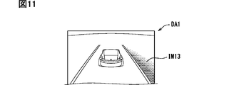
- the display example of FIG. 11 related to the display area DA1 is an example in the case of another vehicle approaching from behind in the lane to the right of the traveling lane in which the vehicle 1 travels in the situation of FIG.
- the red attention image IM13 is displayed in the ambient lighting tone on the right side of the road image IM12.
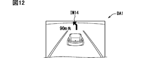
- the display example of FIG. 12 related to the display area DA1 is an example in the case where the route guidance of the car navigation is activated in the situation of FIG.
- a guide image IM14 including, for example, an arrow for guiding a left turn and a character "90 m ahead" is displayed.
- the mode of the host vehicle 1 is the auto cruise control mode
- the inter-vehicle distance to another vehicle in front is set, and the vehicle speed adjustment of the host vehicle 1 is automated.
- the other vehicle image IM15 corresponding to the other vehicle is displayed on the back side of the own vehicle image IM11.
- the display example of FIG. 14 related to the display areas DA2 and DA3 is an example in the case where an audio device separately mounted in the vehicle 1 is accepting a music selection operation.
- the icon corresponding to the audio device is displayed with higher brightness than other icons, and in the display area DA2, the image IM22 representing the information of the music being selected is displayed. ..
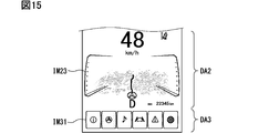
- the display example of FIG. 15 related to the display areas DA2 and DA3 is an example of the case where the route guidance of the car navigation is activated.
- the icon corresponding to the car navigation is displayed with higher brightness than other icons, and in the display area DA2, the image IM23 representing the map around the vehicle is displayed.
- the display surface 12 displays a plurality of icons (for example, the image IM31) representing various kinds of information in the frontmost display area DA3 among the plurality of display areas DA1, DA2, DA3.
- display contents for example, images IM21 and IM22
- a display area DA2 different from the display area on the front side.
- the concave curved portion 14 or the convex curved portion 15 is the convex curved portion 15 that is arranged on the innermost side
- the concave curved portion 14 and the convex curved portion 15 are provided. At least one of them may be provided in two or more.
- the display surface 12 has a plurality of concave curved portions 14 and a plurality of convex curved portions 15
- by arranging the concave curved portions 14 and the convex curved portions 15 alternately one by one In addition to the bird's-eye view, a wavy feeling can be generated.
- the curvature of the concave curved portion 14 and the curvature of the convex curved portion 15 may be different from each other.
- each curved portion 13 may be provided with a curvature also in the left-right direction orthogonal to the depth direction. Even in this case, each curved portion 13 can be regarded as a concave curved portion 14 as long as it is curved concavely on the cross section along the depth direction, and is curved convexly on the cross section along the depth direction. If so, it can be regarded as the convex curved portion 15.
- the display surface 12 may have a flat plane portion.
- a flat surface portion can be provided between the concave curved portion 14 and the convex curved portion 15 instead of the inflection point IP.
- a flat surface portion can be provided between the convex curved portion 15 arranged on the innermost side and the end portion 12b.
- a flat surface portion can be provided between the curved portion 13 and the end portion 12a arranged on the most front side.
- control device 40 does not have to be a device independent of the vehicle display device 10 and the HUD device 30, and is incorporated in the vehicle display device 10 or the HUD device 30. Good.
- any number can be set. It is also possible to set only one display area and display only one important display content on a large screen.
- the display surface 12 may have a touch panel function that receives a touch operation by the user. In that case, only the display area DA3 closest to the front may have the touch panel function.
- a combiner separate from the windshield 3 is installed, and light that can be formed as a virtual image VI is projected on the combiner, and this is a virtual image. You may make it function as the imaging part 3a.
- the display surface 12 and the virtual image forming unit 3a may have a left and right overlapping range, and the left and right positions may be slightly displaced.
- control unit and the method thereof described in the present disclosure are realized by a dedicated computer provided by configuring a processor and a memory programmed to execute one or more functions embodied by a computer program. May be done.
- control unit and the method thereof described in the present disclosure may be realized by a dedicated computer provided by configuring a processor with one or more dedicated hardware logic circuits.
- control unit and the method thereof described in the present disclosure are based on a combination of a processor and a memory programmed to execute one or a plurality of functions and a processor configured by one or more hardware logic circuits. It may be implemented by one or more dedicated computers configured.
- the computer program may be stored in a computer-readable non-transition tangible recording medium as an instruction executed by a computer.
- each section is expressed as, for example, S10. Further, each section can be divided into multiple subsections, while multiple sections can be combined into one section. Further, each section thus configured can be referred to as a device, module, means.
Landscapes
- Engineering & Computer Science (AREA)
- Chemical & Material Sciences (AREA)
- Combustion & Propulsion (AREA)
- Transportation (AREA)
- Mechanical Engineering (AREA)
- Instrument Panels (AREA)
Abstract
L'invention concerne un dispositif d'affichage destiné à un véhicule (1) doté d'une surface d'affichage (12) qui a une pluralité de parties incurvées (13) qui s'incurvent selon une courbure dans un sens de la longueur (DD) orienté de l'avant vers l'arrière d'un véhicule, et qui est conçu de façon à pouvoir afficher une image arrière (RI) vers le haut. La pluralité de parties incurvées ont une partie incurvée concave (14) s'incurvant de manière concave et une partie incurvée convexe (15) s'incurvant de manière convexe dans des emplacements non alignés les uns par rapport aux autres dans le sens de la profondeur. Parmi la partie incurvée concave et la partie incurvée convexe, la plus en avant est la partie incurvée convexe.
Applications Claiming Priority (2)
| Application Number | Priority Date | Filing Date | Title |
|---|---|---|---|
| JP2018210636A JP2020075643A (ja) | 2018-11-08 | 2018-11-08 | 車両用表示装置及び車両用表示システム |
| JP2018-210636 | 2018-11-08 |
Publications (1)
| Publication Number | Publication Date |
|---|---|
| WO2020095923A1 true WO2020095923A1 (fr) | 2020-05-14 |
Family
ID=70611809
Family Applications (1)
| Application Number | Title | Priority Date | Filing Date |
|---|---|---|---|
| PCT/JP2019/043389 Ceased WO2020095923A1 (fr) | 2018-11-08 | 2019-11-06 | Dispositif d'affichage destiné à un véhicule et système d'affichage destiné à un véhicule |
Country Status (2)
| Country | Link |
|---|---|
| JP (1) | JP2020075643A (fr) |
| WO (1) | WO2020095923A1 (fr) |
Families Citing this family (1)
| Publication number | Priority date | Publication date | Assignee | Title |
|---|---|---|---|---|
| JP7826864B2 (ja) * | 2022-06-27 | 2026-03-10 | 株式会社デンソー | 車載表示装置 |
Citations (5)
| Publication number | Priority date | Publication date | Assignee | Title |
|---|---|---|---|---|
| JP2012081780A (ja) * | 2010-10-07 | 2012-04-26 | Stanley Electric Co Ltd | ヘッドアップ表示灯 |
| JP2013088521A (ja) * | 2011-10-14 | 2013-05-13 | Denso Corp | ヘッドアップディスプレイ装置 |
| JP2016113151A (ja) * | 2014-12-16 | 2016-06-23 | 株式会社デンソー | ヘッドアップディスプレイ用カバー部材、および表示装置 |
| JP2016121890A (ja) * | 2014-12-24 | 2016-07-07 | 矢崎総業株式会社 | 表示装置 |
| JP2018112628A (ja) * | 2017-01-10 | 2018-07-19 | 株式会社デンソー | ヘッドアップディスプレイ装置 |
-
2018
- 2018-11-08 JP JP2018210636A patent/JP2020075643A/ja active Pending
-
2019
- 2019-11-06 WO PCT/JP2019/043389 patent/WO2020095923A1/fr not_active Ceased
Patent Citations (5)
| Publication number | Priority date | Publication date | Assignee | Title |
|---|---|---|---|---|
| JP2012081780A (ja) * | 2010-10-07 | 2012-04-26 | Stanley Electric Co Ltd | ヘッドアップ表示灯 |
| JP2013088521A (ja) * | 2011-10-14 | 2013-05-13 | Denso Corp | ヘッドアップディスプレイ装置 |
| JP2016113151A (ja) * | 2014-12-16 | 2016-06-23 | 株式会社デンソー | ヘッドアップディスプレイ用カバー部材、および表示装置 |
| JP2016121890A (ja) * | 2014-12-24 | 2016-07-07 | 矢崎総業株式会社 | 表示装置 |
| JP2018112628A (ja) * | 2017-01-10 | 2018-07-19 | 株式会社デンソー | ヘッドアップディスプレイ装置 |
Also Published As
| Publication number | Publication date |
|---|---|
| JP2020075643A (ja) | 2020-05-21 |
Similar Documents
| Publication | Publication Date | Title |
|---|---|---|
| JP6749981B2 (ja) | 表示装置、表示制御方法、およびプログラム | |
| KR20230034448A (ko) | 차량 및 그 제어 방법 | |
| EP3751329B1 (fr) | Dispositif d'affichage, procédé, système d'affichage tête haute, moyen de transport et support d'informations | |
| US20170031162A1 (en) | Display device for vehicle and display method for vehicle | |
| JP2017072668A (ja) | 表示装置及び表示システム | |
| US20180144673A1 (en) | Multi-layer display system for vehicle dash or the like | |
| JP6136884B2 (ja) | 車両用表示装置 | |
| JPWO2018159319A1 (ja) | ヘッドアップディスプレイ装置及び車載表示システム | |
| JP5659679B2 (ja) | 表示装置 | |
| JP7110968B2 (ja) | ヘッドアップディスプレイ装置 | |
| JP2020056887A (ja) | 表示装置、表示制御方法、およびプログラム | |
| JP2020112667A (ja) | 虚像表示装置 | |
| US20190235290A1 (en) | Display device | |
| CN110816269B (zh) | 显示装置、显示控制方法及存储介质 | |
| JP2020098270A (ja) | 虚像表示装置 | |
| JP2009080178A (ja) | ヘッドアップディスプレイ | |
| US20260110901A1 (en) | Personalized infotainment device for vehicle | |
| JP2020067461A (ja) | 表示装置 | |
| CN112313737B (zh) | 影像显示装置 | |
| WO2020095923A1 (fr) | Dispositif d'affichage destiné à un véhicule et système d'affichage destiné à un véhicule | |
| JP6780960B2 (ja) | 画像表示装置 | |
| JP6579169B2 (ja) | 表示装置 | |
| JP6885215B2 (ja) | 表示装置 | |
| JP2018077455A5 (fr) | ||
| JP2021051231A (ja) | ヘッドアップディスプレイ装置 |
Legal Events
| Date | Code | Title | Description |
|---|---|---|---|
| 121 | Ep: the epo has been informed by wipo that ep was designated in this application |
Ref document number: 19883061 Country of ref document: EP Kind code of ref document: A1 |
|
| NENP | Non-entry into the national phase |
Ref country code: DE |
|
| 122 | Ep: pct application non-entry in european phase |
Ref document number: 19883061 Country of ref document: EP Kind code of ref document: A1 |