WO2020095958A1 - Câble à fibre optique - Google Patents
Câble à fibre optique Download PDFInfo
- Publication number
- WO2020095958A1 WO2020095958A1 PCT/JP2019/043542 JP2019043542W WO2020095958A1 WO 2020095958 A1 WO2020095958 A1 WO 2020095958A1 JP 2019043542 W JP2019043542 W JP 2019043542W WO 2020095958 A1 WO2020095958 A1 WO 2020095958A1
- Authority
- WO
- WIPO (PCT)
- Prior art keywords
- optical fiber
- cable
- fiber cable
- fibrous
- jacket
- Prior art date
- Legal status (The legal status is an assumption and is not a legal conclusion. Google has not performed a legal analysis and makes no representation as to the accuracy of the status listed.)
- Ceased
Links
Images


Classifications
-
- G—PHYSICS
- G02—OPTICS
- G02B—OPTICAL ELEMENTS, SYSTEMS OR APPARATUS
- G02B6/00—Light guides; Structural details of arrangements comprising light guides and other optical elements, e.g. couplings
- G02B6/44—Mechanical structures for providing tensile strength and external protection for fibres, e.g. optical transmission cables
- G02B6/4401—Optical cables
- G02B6/4403—Optical cables with ribbon structure
-
- G—PHYSICS
- G02—OPTICS
- G02B—OPTICAL ELEMENTS, SYSTEMS OR APPARATUS
- G02B6/00—Light guides; Structural details of arrangements comprising light guides and other optical elements, e.g. couplings
- G02B6/44—Mechanical structures for providing tensile strength and external protection for fibres, e.g. optical transmission cables
- G02B6/4401—Optical cables
- G02B6/4429—Means specially adapted for strengthening or protecting the cables
- G02B6/443—Protective covering
- G02B6/4432—Protective covering with fibre reinforcements
-
- G—PHYSICS
- G02—OPTICS
- G02B—OPTICAL ELEMENTS, SYSTEMS OR APPARATUS
- G02B6/00—Light guides; Structural details of arrangements comprising light guides and other optical elements, e.g. couplings
- G02B6/44—Mechanical structures for providing tensile strength and external protection for fibres, e.g. optical transmission cables
- G02B6/4401—Optical cables
- G02B6/4429—Means specially adapted for strengthening or protecting the cables
- G02B6/443—Protective covering
- G02B6/4432—Protective covering with fibre reinforcements
- G02B6/4433—Double reinforcement laying in straight line with optical transmission element
-
- G—PHYSICS
- G02—OPTICS
- G02B—OPTICAL ELEMENTS, SYSTEMS OR APPARATUS
- G02B6/00—Light guides; Structural details of arrangements comprising light guides and other optical elements, e.g. couplings
- G02B6/44—Mechanical structures for providing tensile strength and external protection for fibres, e.g. optical transmission cables
- G02B6/4401—Optical cables
- G02B6/4429—Means specially adapted for strengthening or protecting the cables
- G02B6/4438—Means specially adapted for strengthening or protecting the cables for facilitating insertion by fluid drag in ducts or capillaries
-
- G—PHYSICS
- G02—OPTICS
- G02B—OPTICAL ELEMENTS, SYSTEMS OR APPARATUS
- G02B6/00—Light guides; Structural details of arrangements comprising light guides and other optical elements, e.g. couplings
- G02B6/44—Mechanical structures for providing tensile strength and external protection for fibres, e.g. optical transmission cables
- G02B6/4401—Optical cables
- G02B6/4429—Means specially adapted for strengthening or protecting the cables
- G02B6/443—Protective covering
- G02B6/4431—Protective covering with provision in the protective covering, e.g. weak line, for gaining access to one or more fibres, e.g. for branching or tapping
Definitions
- the present disclosure relates to fiber optic cables.
- This application claims priority based on Japanese application No. 2018-209242 filed on November 6, 2018 and Japanese application No. 2019-104512 filed on June 4, 2019, and is described in the above Japanese application. All the contents described are incorporated.
- FTTH trunk optical fiber cable for example, a loose tube type optical fiber cable (see Patent Document 1) that is mainly used overseas, or an optical fiber tape core wire having intermittent cuts is mounted.
- a slot type optical cable (see Patent Document 2) or a slotless type optical cable (see Patent Document 3) mounted with an optical fiber tape core wire having intermittent cuts has been used.
- An optical fiber cable is an optical fiber cable that has a plurality of intermittently-coupled optical fiber tape cores inside a cable core and has a cable jacket on the outside of the cable core.
- a plurality of pairs of inclusions are provided in two diagonal directions orthogonal to each other in a sectional view of the cable jacket, and at least one diagonal pair of the inclusions is provided with a fibrous inclusion or the fibrous inclusion.
- the FRP used was arranged, and the average linear expansion coefficient of the fibrous inclusions at -40 to + 70 ° C was smaller than the average linear expansion coefficient of the cable jacket at -40 to + 70 ° C.
- the optical fiber tape core wires are stored at a high density, it is possible to relatively mount the optical fiber tape core wires at a high density.
- tension members such as steel wire and FRP (Fiber Reinforced Plastics) on both sides of the cable jacket, there is a bending direction of the slotless optical cable and it is difficult to store the extra length of the cable. was there. Further, when the cable is bent diagonally with respect to the tension member, the bending rigidity of the cable becomes small. Therefore, when the cable inner diameter is large, there is a problem that a kink or the like is likely to occur during installation.
- the structure of the slotless type optical cable is used for the optical fiber cable for pneumatic feeding
- optical fiber cables for pneumatic feeding are required to have a smaller diameter and a lighter weight in order to mount optical fibers at a high density.
- the outer jacket thickness is reduced, only a thin tensile member is put in the outer jacket. Therefore, the rigidity of the optical fiber cable is reduced.
- since there is no skeleton inside the cable there is a problem that the cable jacket is likely to shrink at low temperature and the loss at low temperature is likely to increase.
- the present disclosure has been made in view of these circumstances, and it is to provide a slotless optical fiber cable that suppresses low-temperature shrinkage of a cable jacket, has a small diameter, is lightweight, and has a high density. To aim. (Effect of the present disclosure)
- a slotless optical fiber cable that suppresses low-temperature shrinkage of a cable jacket, has a small diameter, is lightweight, and has a high density.
- An optical fiber cable according to an aspect of the present disclosure has a plurality of intermittent connection type optical fiber tape cores inside a cable core, and an optical fiber cable in which a cable jacket is covered on the outside of the cable core.
- a plurality of pairs of inclusions are provided in two diagonal directions orthogonal to each other in a sectional view of the cable jacket, and at least one diagonal pair of the inclusions has a fibrous inclusion or the fibrous inclusion.
- the average linear expansion coefficient of the fibrous inclusions at ⁇ 40 to + 70 ° C. is preferably less than 1 ⁇ 10 ⁇ 5 / ° C. Further, (3) it is desirable that some or all of the fibrous inclusions have a negative linear expansion coefficient, and (4) some or all of the fibrous inclusions have at least aramid fiber, liquid crystal polymer, or It may be any one of glass fibers. With this configuration, since a fibrous inclusion having a small average linear expansion coefficient is used, it is possible to suppress the shrinkage of the cable jacket at a low temperature of the optical fiber cable.
- the average linear expansion coefficient of the cable jacket at ⁇ 40 to + 70 ° C. is preferably 4.5 ⁇ 10 ⁇ 4 / ° C. or less.
- the ES product obtained by multiplying the Young's modulus E of the cable jacket and the cross-sectional area S of the cable jacket is 1320 to 14400 kgf (12.9 to 141 kN). With this configuration, it is possible to obtain an optical fiber cable having excellent lateral pressure characteristics.
- the thickness of the cable jacket is preferably 0.5 mm or more. With this configuration, the shape of the cable jacket can be favorably maintained when the cable jacket is extrusion-molded.
- the number of the fibrous inclusions is four or more, and two pairs of the two fibrous inclusions that form a pair are provided at positions facing each other across the center of the optical fiber cable in the cross-sectional view.
- the positions of the four fibrous inclusions in a cross-sectional view are preferably positions where two straight lines connecting the two fibrous inclusions forming a pair are orthogonal to each other.
- the four strength members are present inside the cable jacket in a well-balanced manner, so that the bending anisotropy of the optical fiber cable (deviation in the direction of easy bending) can be suppressed.
- the optical fiber cable having the structure when used as an optical fiber cable for pneumatic feeding, the optical fiber cable can favorably perform pneumatic feeding.
- the fibrous inclusion is preferably a plate-shaped member in which the cross section of the fibrous inclusion is formed in an arc shape along the curved surface of the cable jacket.
- the optical fiber cable having the structure when used as an optical fiber cable for pneumatic feeding, the optical fiber cable can favorably perform pneumatic feeding.
- the cable jacket has a protrusion on the outer peripheral portion that protrudes in the radial direction of the optical fiber cable.
- an end portion of the protrusion in a direction in which the protrusion protrudes is formed of a curved surface, and a radius of curvature of the curved surface is 2.5 mm or more.
- the end portion in the protruding direction of the protrusion is formed of a curved surface, and the radius of curvature thereof is 2.5 mm or more, so the end portion has a gentle shape.
- FIG. 1 is a cross-sectional view of an optical fiber cable according to a first embodiment of the present disclosure
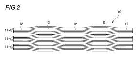
- FIG. 2 is a view showing an intermittent connection type optical fiber tape core wire housed in the optical fiber cable.
- the optical fiber cable 1 shown in FIG. 1 is a slotless type, and has, for example, a round cable core 20 and a cable jacket 30 formed around the cable core 20.
- the cable core 20 accommodates, for example, 1800 cores by using 150 pieces of 12 intermittently-connecting type optical fiber tape core wires (hereinafter, also referred to as “intermittent tape core wires”) 10.
- 30 pieces of the intermittent tape core wires 10 are bundled by a coarse winding string (not shown) or the like into a unit, and five units are formed.
- the intermittent tape core wire 10 is composed of a plurality of optical fiber core wires 11 arranged in a parallel row, and adjacent optical fiber core wires are intermittently connected by a connecting portion 12 and a non-connecting portion 13. It will be done. Specifically, the example shown in FIG. 2 shows a state in which the intermittent tape core wire 10 is opened in the arrangement direction, and the intermittent tape core wire 10 has 12 optical fiber core wires 11 arranged in a parallel row. Two cores are intermittently bonded to each other. In addition, the intermittent tape core wire 10 does not need to provide the connection part 12 and the non-connection part 13 for every two cores, for example, may connect intermittently with the connection part 12 and the non-connection part 13 for every one core. ..
- the optical fiber core wire 11 arranged as the intermittent tape core wire 10 is an optical fiber element wire in which a glass fiber having a standard outer diameter of 125 ⁇ m is coated with a coating outer diameter of about 250 ⁇ m, and a colored coating is further applied to the outside. Is.
- the optical fiber core wire 11 is not limited to this, and may be a small diameter fiber having a coating outer diameter in the range of 135 ⁇ m to 220 ⁇ m, for example, about 165 ⁇ m or 200 ⁇ m. The use of a small-diameter fiber facilitates high-density mounting.
- the cable core 20 is, for example, a unit formed by bundling 30 pieces of the intermittent tape core wires 10 in a round shape by vertically or horizontally winding them with a press winding tape 21.
- Each unit has a structure in which it is twisted in one direction or by SZ twisting.
- the intermittent tape core wire 10 can be freely deformed in the cable core 20, it is effective in increasing the density.
- the outside of the press-winding tape 21 is covered with a cable jacket 30 made of, for example, L-LDPE (Linear Low Density Polyethylene) or HDPE (High Density Polyethylene).
- the coefficient of linear expansion of the cable jacket 30 itself is preferably 4.5 ⁇ 10 ⁇ 4 / ° C. or less in the operating temperature range of ⁇ 40 to + 70 ° C.
- a second fibrous inclusion 32 which plays a role as a tear string when the cable jacket 30 is torn, is vertically embedded in the other diagonal pair when the cable jacket 30 is extrusion-molded.
- substantially orthogonal includes a state in which the state is deviated from the state of being orthogonal at 90 ° by several degrees.
- the first fibrous inclusions 31 not only serve as tension members, but also serve to suppress jacket shrinkage during low temperature shrinkage, and have an average linear expansion coefficient smaller than the average linear expansion coefficient of the cable jacket 30 itself. It is desirable that the material has As a material of the first fibrous inclusions 31, a part or all of aramid fibers having a negative linear expansion coefficient, a liquid crystal polymer having a low linear expansion coefficient (about 0.5 ⁇ 10 ⁇ 5 / ° C.), Glass fiber or the like is preferable.
- the linear expansion coefficient of the first fibrous inclusions 31 at ⁇ 40 to + 70 ° C. is preferably less than 1 ⁇ 10 ⁇ 5 / ° C.
- the first fibrous inclusions 31 may be embedded as fibers with FRP (fiber reinforced plastic).
- FRP using fibrous inclusions means FRP (fiber reinforced plastic) using fibrous inclusions as fibers.
- a part of the first fibrous inclusions 31 may be any one of aramid fiber, liquid crystal polymer, and glass fiber.
- the second fibrous inclusion 32 plays a role as a tear string when the cable jacket 30 is torn, and therefore it is desirable that the second fibrous inclusion 32 be in contact with the press-winding tape 21 or be embedded in a position near the press-winding tape 21.
- the material of the second fibrous inclusions 32 for example, the same material as that of the first fibrous inclusions 31 can be used. In this case, since the fibrous inclusions of the same material are present at four locations of two diagonal pairs, the anisotropy of the bending direction is suppressed during cable bending, and the bending directionality is improved. Thereby, it is possible to suppress a kink when laying the optical fiber cable.
- the second fibrous inclusions 32 need not be FRP because they require flexibility.
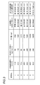
- FIG. 3 is a diagram showing various cable jacket conditions and characteristic evaluation results.
- the cross-sectional area of the cable jacket 30 is S and the Young's modulus is E
- various ES products are changed.
- the increase in loss due to flat plate lateral pressure and jacket shrinkage was evaluated.
- As the flat plate side pressure an increase amount [dB] of transmission loss when a weight of 500 N was applied to the stretched optical fiber cable over a length of 100 mm was obtained.
- an increase amount [dB] of transmission loss when the temperature was changed from room temperature to ⁇ 40 ° C. was obtained.
- the ES product of the jacket is related to the lateral pressure of the flat plate.
- the smaller the ES product the weaker the lateral pressure is because the optical fiber cable is soft and thin.
- the ES product is also related to the low temperature loss. The larger the ES product is, the larger the shrinkage of the jacket is, and thus the low temperature characteristics are deteriorated.
- aramid FRP having a diameter of 0.5 mm was used as the first fibrous inclusions 31 having a pair of diagonals for the seven examples of Samples 1 to 7.
- the thickness of the cable jacket is 0.5 mm or more in order to maintain a good shape of the cable jacket 30 when the cable jacket 30 is extrusion-molded, and from the viewpoint of reducing the diameter of the optical fiber cable 1. It was set to 2.0 mm or less.
- the material for the cable jackets 30 of Samples 1, 3, and 4 is low-density polyethylene having a Young's modulus of 90 (kgf / mm 2 ), and an average linear expansion coefficient at ⁇ 40 to + 70 ° C. of 4.5 ⁇ 10.
- the material of the cable jacket 30 of sample 2 is medium density polyethylene having a Young's modulus of 110 (kgf / mm 2 ) and an average linear expansion coefficient at -40 to + 70 ° C. 4.0 ⁇ 10 ⁇ 4 / ° C.
- the material of the cable jacket 30 of Samples 5, 6 and 7 is high density polyethylene having a Young's modulus of 240 (kgf / mm 2 ), -40 to The average linear expansion coefficient at + 70 ° C. is 3.7 ⁇ 10 ⁇ 4 / ° C.
- FIG. 4 is a sectional view perpendicular to the length direction of the optical fiber cable 1A.
- the optical fiber cable 1 ⁇ / b> A covers a plurality of optical fiber ribbons 10, a water absorbing tape (holding tape) 21 that covers the periphery of the optical fiber ribbons 10, and a periphery of the water absorbing tape 21.
- the cable jacket 30 is provided with a tensile strength member 5 ⁇ / b> A and a tear string 6 provided inside the cable jacket 30.
- both the tensile strength member 5A and the tear string 6 are fibrous inclusions.
- the water-absorbing tape 21 is wound around the entire plurality of optical fiber tape core wires 10 in, for example, vertical attachment or horizontal winding.
- the water absorbing tape 21 is, for example, a base cloth made of polyester or the like that has been subjected to a water absorbing process by adhering a water absorbing powder thereto.
- the cable jacket 30 is made of, for example, a resin such as polyethylene (PE).
- the resin of the cable jacket 30 preferably has a Young's modulus of 500 Pa or more.
- the cable jacket 30 contains a silicon-based lubricant.
- the silicon-based lubricant is preferably contained in a proportion of 2 wt% or more, for example.
- the cable jacket 30 is, for example, a thermoplastic resin and is formed by extruding a resin on the plurality of optical fiber tape core wires 10 around which the water absorbing tape 21 is wound.
- the tensile strength member 5A is provided so as to be embedded inside the cable jacket 30.
- the strength member 5A is made of fiber reinforced plastic (FRP).
- the tensile strength member 5A is, for example, aramid FRP, glass FRP, carbon FRP or the like, but it is preferable to use aramid FRP having excellent flexibility. Since the aramid FRP has a smaller linear expansion coefficient than the cable jacket 30, it is possible to suppress shrinkage of the cable jacket 30 at low temperatures.
- the tensile member 5A is formed in a circular shape in cross section. A plurality of tensile strength members 5A (four in this example) are provided.
- Each of the four strength members 5A is provided with two pairs of strength members 5A that are paired at positions facing each other across the center of the optical fiber cable in a cross-sectional view.
- the positions of the four strength members 5A in a cross-sectional view are the positions where two straight lines connecting the two strength members 5A forming a pair are orthogonal to each other.
- Each strength member 5A is provided in the cable jacket 30 along the longitudinal direction of the optical fiber cable 1A.
- the tear string 6 is for tearing the cable jacket 30, and is embedded in the cable jacket 30 along the longitudinal direction of the optical fiber cable 1A.
- two tear cords 6 are provided.
- the two tear cords 6 are provided so as to face each other at a substantially intermediate position between the adjacent tensile strength members 5A.
- the tear string 6 is formed of, for example, a plastic material (for example, polyester) that is resistant to pulling.
- the ratio of the total cross-sectional area of the four strength members 5A to the cross-sectional area of the member forming the cable jacket 30 is 2.4% or more.
- the ratio of the total cross-sectional area is 2.42%.
- the loss temperature characteristic at ⁇ 30 to + 70 ° C. is 0.1 dB / km or less, so the ratio of the total cross-sectional area of the four strength members 5A to the cross-sectional area of the member forming the cable jacket 30. Is preferably 2.4% or more.
- the optical fiber tape core wire 10 is rolled into a gathered state when housed in the optical fiber cable 1A.
- a plurality of optical fiber ribbons 10 may be twisted together to form a unit, and the plurality of units may be assembled.
- the plurality of optical fiber ribbons 10 in the assembled state may be bundled with a bundle material or the like, or may be bundled with the bundle material or the like for each unit.
- the optical fiber cable 1A two pairs of two tensile strength members 5A that are paired are provided inside the cable jacket 30 at positions facing each other across the center of the optical fiber cable 1A in a cross-sectional view. That is, the optical fiber cable 1A is provided with four strength members 5A inside the cable jacket 30.
- the positions of the four strength members 5A in a cross-sectional view are positions where two straight lines connecting the two strength members 5A forming a pair are orthogonal to each other. Since the four strength members 5A are present inside the cable jacket 30 in a well-balanced manner, it is possible to suppress the bending anisotropy of the optical fiber cable 1A (deviation in the direction of easy bending).
- the optical fiber cable having bending rigidity suitable for pneumatic feeding can be obtained. Also in the second embodiment, by making the average linear expansion coefficient of the fibrous inclusions at ⁇ 40 to + 70 ° C. smaller than the average linear expansion coefficient of the cable jacket at ⁇ 40 to + 70 ° C., the low temperature shrinkage is caused. The loss increase can be suppressed.
- An optical fiber cable 1B according to the third embodiment will be described with reference to FIG.
- the same components as those of the optical fiber cable 1A according to the second embodiment described above are designated by the same reference numerals, and the description thereof will be omitted.
- the third embodiment as in the first embodiment, the relationship between the average linear expansion coefficient of the fibrous inclusions and the average linear expansion coefficient of the cable jacket is satisfied.
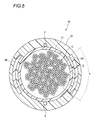
- FIG. 5 is a cross-sectional view perpendicular to the length direction of the optical fiber cable 1B.
- the optical fiber cable 1B includes a plurality of intermittently connected optical fiber tape core wires 10, a water absorbing tape 21 that covers the periphery of the optical fiber tape core wire 10, and a cable that covers the periphery of the water absorbing tape 21.
- the jacket 30 includes a tensile strength member 5 ⁇ / b> B and a tear string 6 provided inside the cable jacket 30.
- the tensile strength member 5B is a plate-shaped tensile strength member whose cross section is formed in an arc shape along the curved surface of the cable jacket 30.
- both the tensile strength member 5B and the tear cord 6 are fibrous inclusions.
- a plurality of tensile strength members 5B are provided.
- the two strength members 5B are provided inside the cable jacket 30 and are arranged so as to face each other.
- the strength member 5B is provided, for example, in an arc shape having a central angle ⁇ in the range of 30 ° to 90 ° in the optical fiber cable 1B.
- the total cross-sectional area of the two strength members 5B is 2.4% or more of the cross-sectional area of the member forming the cable jacket 30.
- the radial thickness B of the strength member 5B is adjusted according to the length of the arc of the strength member 5B along the curved surface of the cable jacket 30.
- the tensile strength member 5B is a plate-shaped member formed of fiber reinforced plastic such as aramid or glass, and is provided along the longitudinal direction of the optical fiber cable 1B like the tensile strength member 5A of the second embodiment. .. Other configurations are similar to those of the optical fiber cable 1A.
- the body 5B is buried. Therefore, the optical fiber cable 1B can further suppress the bending anisotropy as compared with the case of the optical fiber cable having a structure having tensile strength members whose cross section is circular on both sides of the jacket. Further, the rigidity of the optical fiber cable 1B can be appropriately increased. Thereby, the optical fiber cable suitable for pneumatic feeding can be obtained.
- the average linear expansion coefficient of the fibrous inclusions at ⁇ 40 to + 70 ° C. smaller than the average linear expansion coefficient of the cable jacket at ⁇ 40 to + 70 ° C., the low temperature shrinkage is caused. The loss increase can be suppressed.
- An optical fiber cable 1C according to the fourth embodiment will be described with reference to FIG.
- the same components as those of the optical fiber cable 1A according to the second embodiment described above are designated by the same reference numerals, and the description thereof will be omitted.
- the relationship between the average linear expansion coefficient of the fibrous inclusions and the average linear expansion coefficient of the cable jacket is satisfied, as in the first embodiment.
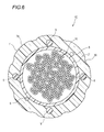
- FIG. 6 is a sectional view perpendicular to the length direction of the optical fiber cable 1C.
- the optical fiber cable 1C includes a plurality of intermittently connected optical fiber tape core wires 10, a water absorbing tape 21 that covers the periphery of the optical fiber tape core wire 10, and a cable that covers the periphery of the water absorbing tape 21.
- the jacket 30 includes a tensile strength member 5 and a tear cord 6 provided inside the cable jacket 30.
- the tensile strength member 5 is illustrated as being similar to the four tensile strength members 5A in the optical fiber cable 1A according to the second embodiment whose cross-sectional view is formed in a circular shape, it is related to the third embodiment.
- the optical fiber cable 1B may be the same as the two tensile strength members 5B having a plate-shaped cross section. Also in the fourth embodiment, as in the first embodiment, both the tensile strength member 5 and the tear cord 6 are fibrous inclusions. Further, the optical fiber cable 1C has a protrusion 7 on the outer peripheral portion of the cable jacket 30.
- a plurality of protrusions 7 (8 in this example) are provided.
- the eight projections 7 are provided along the longitudinal direction of the optical fiber cable 1C.
- Each protrusion 7 may be provided continuously along the longitudinal direction or may be provided intermittently. Further, the eight projections 7 are provided on the outer peripheral portion of the cable jacket 30 at substantially equal intervals in a sectional view.
- the protrusion 7 has a curved end surface 7a in the protruding direction of the protrusion 7, and is formed such that the radius of curvature of the curved surface is 2.5 mm or more.
- the protrusion 7 is formed integrally with the cable jacket 30 by extrusion molding. Other configurations are the same as those of the optical fiber cable 1A.
- the plurality of protrusions 7 are provided on the outer peripheral portion of the cable jacket 30 along the longitudinal direction of the optical fiber cable 1C. Therefore, when the optical fiber cable 1C is pneumatically fed in the duct, the projection 7 comes into contact with the inner wall of the duct, so that the contact area between the cable jacket 30 and the duct can be reduced. As a result, the friction between the cable jacket 30 and the duct is reduced, and the pumping distance can be extended. Also in the fourth embodiment, by making the average linear expansion coefficient of the fibrous inclusions at ⁇ 40 to + 70 ° C. smaller than the average linear expansion coefficient of the cable jacket at ⁇ 40 to + 70 ° C., the low temperature shrinkage is caused. The loss increase can be suppressed.
- the protrusion 7 has a curved end 7a in the protruding direction, and is formed to have a gentle shape with a radius of curvature of 2.5 mm or more. ..
- a wiring member such as a closure
- Optical fiber cable 10 ... Intermittent tape core wire 11 . Optical fiber core wire 12 ... Connection part 13 ... Non-connection part 20 ... Cable core 21 ... Pressing tape 30 ... Cable jacket 31 . First Fibrous inclusions 32 . Second fibrous inclusions 5, 5A, 5B . Strength member 6 ... Tear string 7 ... Projection
Landscapes
- Physics & Mathematics (AREA)
- General Physics & Mathematics (AREA)
- Optics & Photonics (AREA)
- Insulated Conductors (AREA)
- Light Guides In General And Applications Therefor (AREA)
- Communication Cables (AREA)
Abstract
L'invention concerne un câble à fibre optique comprenant une pluralité de rubans de fibres optiques connectés par intermittence à l'intérieur d'une gaine externe de câble, où un matériau à fibres intercalées ou un PVR utilisant ledit matériau à fibres intercalées est inclus dans au moins une paire diagonale parmi deux directions diagonales sensiblement perpendiculaires à l'intérieur de la gaine externe de câble. Un coefficient de dilatation linéaire moyen du matériau à fibres intercalées entre -40 et +70°C est inférieur à un coefficient de dilatation linéaire moyen de la gaine externe de câble entre -40 et +70°C.
Priority Applications (3)
| Application Number | Priority Date | Filing Date | Title |
|---|---|---|---|
| CN201980068307.6A CN112867952B (zh) | 2018-11-06 | 2019-11-06 | 光纤缆线 |
| EP19881929.4A EP3879323B1 (fr) | 2018-11-06 | 2019-11-06 | Câble à fibre optique |
| US17/290,315 US11378766B2 (en) | 2018-11-06 | 2019-11-06 | Optical fiber cable |
Applications Claiming Priority (4)
| Application Number | Priority Date | Filing Date | Title |
|---|---|---|---|
| JP2018-209242 | 2018-11-06 | ||
| JP2018209242A JP7135744B2 (ja) | 2018-11-06 | 2018-11-06 | 光ファイバケーブル |
| JP2019-104512 | 2019-06-04 | ||
| JP2019104512A JP7156178B2 (ja) | 2019-06-04 | 2019-06-04 | 光ファイバケーブル |
Publications (1)
| Publication Number | Publication Date |
|---|---|
| WO2020095958A1 true WO2020095958A1 (fr) | 2020-05-14 |
Family
ID=70612017
Family Applications (1)
| Application Number | Title | Priority Date | Filing Date |
|---|---|---|---|
| PCT/JP2019/043542 Ceased WO2020095958A1 (fr) | 2018-11-06 | 2019-11-06 | Câble à fibre optique |
Country Status (4)
| Country | Link |
|---|---|
| US (1) | US11378766B2 (fr) |
| EP (1) | EP3879323B1 (fr) |
| CN (1) | CN112867952B (fr) |
| WO (1) | WO2020095958A1 (fr) |
Cited By (6)
| Publication number | Priority date | Publication date | Assignee | Title |
|---|---|---|---|---|
| JP2021196567A (ja) * | 2020-06-18 | 2021-12-27 | 株式会社フジクラ | 光ファイバケーブル |
| WO2022092019A1 (fr) * | 2020-10-26 | 2022-05-05 | 住友電気工業株式会社 | Câble à fibres optiques et câble avec connecteur |
| JPWO2022244584A1 (fr) * | 2021-05-18 | 2022-11-24 | ||
| TWI796154B (zh) * | 2022-03-04 | 2023-03-11 | 中華電信股份有限公司 | 光纜 |
| WO2023113012A1 (fr) * | 2021-12-17 | 2023-06-22 | 住友電気工業株式会社 | Câble à fibres optiques |
| EP4174543A4 (fr) * | 2020-06-29 | 2024-08-14 | Sumitomo Electric Industries, Ltd. | Câble à fibre optique |
Families Citing this family (5)
| Publication number | Priority date | Publication date | Assignee | Title |
|---|---|---|---|---|
| HUE067399T2 (hu) * | 2018-10-11 | 2024-10-28 | Fujikura Ltd | Optikai kábel |
| EP3992685A1 (fr) * | 2020-10-27 | 2022-05-04 | Sterlite Technologies Limited | Conception de gaine ondulée résistant aux fuites de gaz pour la réduction de frottement dans des câbles à fibres optiques |
| CA3213133A1 (fr) * | 2021-08-31 | 2023-03-09 | Ls Cable & System Ltd. | Cable optique |
| US11640035B1 (en) | 2021-11-24 | 2023-05-02 | Sterlite Technologies Limited | Optical fibre cable for air blowing installation |
| TWI853464B (zh) * | 2022-03-02 | 2024-08-21 | 日商藤倉股份有限公司 | 光纜、撕裂繩的脫落方法及光纖的引線方法 |
Citations (16)
| Publication number | Priority date | Publication date | Assignee | Title |
|---|---|---|---|---|
| JPS5541882U (fr) * | 1978-09-11 | 1980-03-18 | ||
| US4770489A (en) * | 1986-08-27 | 1988-09-13 | Sumitomo Electric Research Triangle, Inc. | Ruggedized optical communication cable |
| JPH10133074A (ja) * | 1996-10-31 | 1998-05-22 | Fujikura Ltd | 架空光ファイバケーブル |
| JP2004184539A (ja) * | 2002-11-29 | 2004-07-02 | Fujikura Ltd | 光ケーブル |
| US6785450B2 (en) | 2000-05-26 | 2004-08-31 | Corning Cable Systems Llc | Self-supporting fiber optic cable |
| JP2006023503A (ja) * | 2004-07-07 | 2006-01-26 | Furukawa Electric Co Ltd:The | 通信用ケーブル |
| US7050688B2 (en) | 2003-07-18 | 2006-05-23 | Corning Cable Systems Llc | Fiber optic articles, assemblies, and cables having optical waveguides |
| JP2009244288A (ja) | 2008-03-28 | 2009-10-22 | Toyokuni Electric Cable Co Ltd | コネクタ付光ファイバケーブル |
| JP2010008923A (ja) | 2008-06-30 | 2010-01-14 | Nippon Telegr & Teleph Corp <Ntt> | 光ファイバケーブル |
| US20120288245A1 (en) | 2008-12-02 | 2012-11-15 | Hurley William C | Optical fiber array cables and associated fiber optic cables and systems |
| US20130051742A1 (en) | 2011-08-25 | 2013-02-28 | Benjamin Roberts Blackwell | Drop cable assembly |
| JP2014071441A (ja) | 2012-10-02 | 2014-04-21 | Fujikura Ltd | 光ファイバケーブル |
| US8879878B2 (en) | 2011-07-01 | 2014-11-04 | Draka Comteq, B.V. | Multimode optical fiber |
| JP2015517679A (ja) | 2012-05-02 | 2015-06-22 | エーエフエル・テレコミュニケーションズ・エルエルシー | リボン型光ファイバー構造体を有する円形で小径の光ケーブル |
| US9176292B2 (en) | 2006-05-11 | 2015-11-03 | Ccs Technology, Inc. | Fiber optic distribution cables and structures therefor |
| JP2019104512A (ja) | 2017-12-11 | 2019-06-27 | 花王株式会社 | 吐出ノズル付きキャップ |
Family Cites Families (18)
| Publication number | Priority date | Publication date | Assignee | Title |
|---|---|---|---|---|
| US5201020A (en) * | 1990-11-08 | 1993-04-06 | Corning Incorporated | Reinforced protective tube for optical waveguide fibers |
| FR2785994B1 (fr) | 1998-11-18 | 2001-03-16 | Sagem | Cable a fibres optiques maintenues dans une gaine |
| US6621966B2 (en) * | 1999-03-31 | 2003-09-16 | Corning Cable Systems Llc | Fiber optic cable with profiled group of optical fibers |
| US6519399B2 (en) * | 2001-02-19 | 2003-02-11 | Corning Cable Systems Llc | Fiber optic cable with profiled group of optical fibers |
| US6839494B2 (en) | 2003-03-18 | 2005-01-04 | 3M Innovative Properties Company | Dual stage fiber optic cable design |
| JPWO2004102244A1 (ja) * | 2003-05-15 | 2006-07-13 | 旭硝子株式会社 | プラスチック光ファイバケーブル |
| AU2006236409B2 (en) | 2005-04-19 | 2011-05-19 | Adc Telecommunications, Inc. | Loop back plug and method |
| US20060291787A1 (en) | 2005-06-27 | 2006-12-28 | Seddon David A | Fiber optic cable having strength component |
| JP5294585B2 (ja) * | 2007-08-02 | 2013-09-18 | 株式会社フジクラ | 光ファイバケーブル |
| WO2010001663A1 (fr) * | 2008-06-30 | 2010-01-07 | 日本電信電話株式会社 | Câble à fibres optiques et bande à fibres optiques |
| WO2011130642A2 (fr) | 2010-04-16 | 2011-10-20 | Adc Telecommunications, Inc. | Ensemble câble à fibres optiques et procédé de fabrication de ce dernier |
| US9052459B2 (en) | 2012-03-23 | 2015-06-09 | Corning Cable Systems Llc | Cable assembly and method |
| JP5719052B1 (ja) * | 2014-03-06 | 2015-05-13 | 株式会社フジクラ | 光ケーブル |
| CN204680451U (zh) * | 2015-04-23 | 2015-09-30 | 远东电缆有限公司 | 气动吹入式光纤复合智慧能源用电力电缆 |
| JP6542648B2 (ja) | 2015-11-20 | 2019-07-10 | 住友電気工業株式会社 | 光ファイバケーブル |
| JP2017134267A (ja) * | 2016-01-28 | 2017-08-03 | 住友電気工業株式会社 | 光ファイバケーブル |
| EP3543755B1 (fr) | 2016-11-17 | 2024-08-21 | Fujikura, Ltd. | Câble de fibre optique et procédé de fabrication d'un câble de fibre optique |
| US10663682B2 (en) * | 2017-11-20 | 2020-05-26 | Corning Research & Development Corporation | Low shrink and small bend performing drop cable |
-
2019
- 2019-11-06 CN CN201980068307.6A patent/CN112867952B/zh active Active
- 2019-11-06 WO PCT/JP2019/043542 patent/WO2020095958A1/fr not_active Ceased
- 2019-11-06 EP EP19881929.4A patent/EP3879323B1/fr active Active
- 2019-11-06 US US17/290,315 patent/US11378766B2/en active Active
Patent Citations (18)
| Publication number | Priority date | Publication date | Assignee | Title |
|---|---|---|---|---|
| JPS5541882U (fr) * | 1978-09-11 | 1980-03-18 | ||
| US4770489A (en) * | 1986-08-27 | 1988-09-13 | Sumitomo Electric Research Triangle, Inc. | Ruggedized optical communication cable |
| JPH10133074A (ja) * | 1996-10-31 | 1998-05-22 | Fujikura Ltd | 架空光ファイバケーブル |
| US6785450B2 (en) | 2000-05-26 | 2004-08-31 | Corning Cable Systems Llc | Self-supporting fiber optic cable |
| JP2004184539A (ja) * | 2002-11-29 | 2004-07-02 | Fujikura Ltd | 光ケーブル |
| US7050688B2 (en) | 2003-07-18 | 2006-05-23 | Corning Cable Systems Llc | Fiber optic articles, assemblies, and cables having optical waveguides |
| JP2006023503A (ja) * | 2004-07-07 | 2006-01-26 | Furukawa Electric Co Ltd:The | 通信用ケーブル |
| US9176292B2 (en) | 2006-05-11 | 2015-11-03 | Ccs Technology, Inc. | Fiber optic distribution cables and structures therefor |
| US9494764B2 (en) | 2006-05-11 | 2016-11-15 | Corning Optical Communications LLC | Fiber optic distribution cables and structures therefor |
| US9341805B2 (en) | 2006-05-11 | 2016-05-17 | Ccs Technology, Inc. | Fiber optic distribution cables and structures therefor |
| JP2009244288A (ja) | 2008-03-28 | 2009-10-22 | Toyokuni Electric Cable Co Ltd | コネクタ付光ファイバケーブル |
| JP2010008923A (ja) | 2008-06-30 | 2010-01-14 | Nippon Telegr & Teleph Corp <Ntt> | 光ファイバケーブル |
| US20120288245A1 (en) | 2008-12-02 | 2012-11-15 | Hurley William C | Optical fiber array cables and associated fiber optic cables and systems |
| US8879878B2 (en) | 2011-07-01 | 2014-11-04 | Draka Comteq, B.V. | Multimode optical fiber |
| US20130051742A1 (en) | 2011-08-25 | 2013-02-28 | Benjamin Roberts Blackwell | Drop cable assembly |
| JP2015517679A (ja) | 2012-05-02 | 2015-06-22 | エーエフエル・テレコミュニケーションズ・エルエルシー | リボン型光ファイバー構造体を有する円形で小径の光ケーブル |
| JP2014071441A (ja) | 2012-10-02 | 2014-04-21 | Fujikura Ltd | 光ファイバケーブル |
| JP2019104512A (ja) | 2017-12-11 | 2019-06-27 | 花王株式会社 | 吐出ノズル付きキャップ |
Non-Patent Citations (1)
| Title |
|---|
| See also references of EP3879323A4 |
Cited By (11)
| Publication number | Priority date | Publication date | Assignee | Title |
|---|---|---|---|---|
| JP2021196567A (ja) * | 2020-06-18 | 2021-12-27 | 株式会社フジクラ | 光ファイバケーブル |
| EP4174543A4 (fr) * | 2020-06-29 | 2024-08-14 | Sumitomo Electric Industries, Ltd. | Câble à fibre optique |
| WO2022092019A1 (fr) * | 2020-10-26 | 2022-05-05 | 住友電気工業株式会社 | Câble à fibres optiques et câble avec connecteur |
| JPWO2022092019A1 (fr) * | 2020-10-26 | 2022-05-05 | ||
| JP7652192B2 (ja) | 2020-10-26 | 2025-03-27 | 住友電気工業株式会社 | 光ファイバケーブルおよびコネクタ付きケーブル |
| US12510716B2 (en) | 2020-10-26 | 2025-12-30 | Sumitomo Electric Industries, Ltd. | Optical fiber cable and cable with connector |
| JPWO2022244584A1 (fr) * | 2021-05-18 | 2022-11-24 | ||
| WO2022244584A1 (fr) * | 2021-05-18 | 2022-11-24 | 株式会社フジクラ | Câble à fibres optiques |
| JP7609982B2 (ja) | 2021-05-18 | 2025-01-07 | 株式会社フジクラ | 光ファイバケーブル |
| WO2023113012A1 (fr) * | 2021-12-17 | 2023-06-22 | 住友電気工業株式会社 | Câble à fibres optiques |
| TWI796154B (zh) * | 2022-03-04 | 2023-03-11 | 中華電信股份有限公司 | 光纜 |
Also Published As
| Publication number | Publication date |
|---|---|
| EP3879323B1 (fr) | 2022-12-14 |
| EP3879323A4 (fr) | 2022-01-26 |
| EP3879323A1 (fr) | 2021-09-15 |
| US11378766B2 (en) | 2022-07-05 |
| CN112867952A (zh) | 2021-05-28 |
| CN112867952B (zh) | 2023-01-06 |
| US20220003949A1 (en) | 2022-01-06 |
Similar Documents
| Publication | Publication Date | Title |
|---|---|---|
| WO2020095958A1 (fr) | Câble à fibre optique | |
| US6101305A (en) | Fiber optic cable | |
| US20230418013A1 (en) | Optical fiber cable | |
| US6654527B2 (en) | Optical fiber cable | |
| US12510716B2 (en) | Optical fiber cable and cable with connector | |
| NZ546107A (en) | Signal transmitting cable | |
| US12535645B2 (en) | Optical fiber cable and cable with connector | |
| JP6542648B2 (ja) | 光ファイバケーブル | |
| JP5840911B2 (ja) | 光ファイバケーブル | |
| JP7135744B2 (ja) | 光ファイバケーブル | |
| CN213399003U (zh) | 一种双芯扁形室内用复合光缆 | |
| JP2001051169A (ja) | 光ケーブル | |
| JP7310517B2 (ja) | 光ファイバケーブル | |
| JPH10148739A (ja) | 架空集合屋外用光ケーブル | |
| JP2004212960A (ja) | 光ファイバケーブル | |
| US11640035B1 (en) | Optical fibre cable for air blowing installation | |
| US20250004236A1 (en) | Optical cable, optical cable structure, and method for manufacturing optical cable | |
| WO2023135808A1 (fr) | Câble à fibre optique | |
| JP2025180970A (ja) | 光ファイバケーブル | |
| WO2025135055A1 (fr) | Câble à fibre optique | |
| WO2024218908A1 (fr) | Câble à fibre optique et câble avec connecteur | |
| JPS61230108A (ja) | プラスチツク光フアイバ−ケ−ブル | |
| JP2023155697A (ja) | 光ケーブル | |
| JPH0990181A (ja) | 光ファイバケーブル | |
| KR20250130180A (ko) | 광케이블 |
Legal Events
| Date | Code | Title | Description |
|---|---|---|---|
| 121 | Ep: the epo has been informed by wipo that ep was designated in this application |
Ref document number: 19881929 Country of ref document: EP Kind code of ref document: A1 |
|
| NENP | Non-entry into the national phase |
Ref country code: DE |
|
| ENP | Entry into the national phase |
Ref document number: 2019881929 Country of ref document: EP Effective date: 20210607 |