WO2020095965A1 - Structure d'admission de moteur à combustion interne - Google Patents
Structure d'admission de moteur à combustion interne Download PDFInfo
- Publication number
- WO2020095965A1 WO2020095965A1 PCT/JP2019/043558 JP2019043558W WO2020095965A1 WO 2020095965 A1 WO2020095965 A1 WO 2020095965A1 JP 2019043558 W JP2019043558 W JP 2019043558W WO 2020095965 A1 WO2020095965 A1 WO 2020095965A1
- Authority
- WO
- WIPO (PCT)
- Prior art keywords
- intake
- exhaust gas
- gas recirculation
- intake manifold
- internal combustion
- Prior art date
- Legal status (The legal status is an assumption and is not a legal conclusion. Google has not performed a legal analysis and makes no representation as to the accuracy of the status listed.)
- Ceased
Links
Images



Classifications
-
- F—MECHANICAL ENGINEERING; LIGHTING; HEATING; WEAPONS; BLASTING
- F02—COMBUSTION ENGINES; HOT-GAS OR COMBUSTION-PRODUCT ENGINE PLANTS
- F02M—SUPPLYING COMBUSTION ENGINES IN GENERAL WITH COMBUSTIBLE MIXTURES OR CONSTITUENTS THEREOF
- F02M26/00—Engine-pertinent apparatus for adding exhaust gases to combustion-air, main fuel or fuel-air mixture, e.g. by exhaust gas recirculation [EGR] systems
- F02M26/13—Arrangement or layout of EGR passages, e.g. in relation to specific engine parts or for incorporation of accessories
- F02M26/17—Arrangement or layout of EGR passages, e.g. in relation to specific engine parts or for incorporation of accessories in relation to the intake system
- F02M26/19—Means for improving the mixing of air and recirculated exhaust gases, e.g. venturis or multiple openings to the intake system
-
- F—MECHANICAL ENGINEERING; LIGHTING; HEATING; WEAPONS; BLASTING
- F02—COMBUSTION ENGINES; HOT-GAS OR COMBUSTION-PRODUCT ENGINE PLANTS
- F02M—SUPPLYING COMBUSTION ENGINES IN GENERAL WITH COMBUSTIBLE MIXTURES OR CONSTITUENTS THEREOF
- F02M26/00—Engine-pertinent apparatus for adding exhaust gases to combustion-air, main fuel or fuel-air mixture, e.g. by exhaust gas recirculation [EGR] systems
- F02M26/13—Arrangement or layout of EGR passages, e.g. in relation to specific engine parts or for incorporation of accessories
- F02M26/42—Arrangement or layout of EGR passages, e.g. in relation to specific engine parts or for incorporation of accessories having two or more EGR passages; EGR systems specially adapted for engines having two or more cylinders
- F02M26/44—Arrangement or layout of EGR passages, e.g. in relation to specific engine parts or for incorporation of accessories having two or more EGR passages; EGR systems specially adapted for engines having two or more cylinders in which a main EGR passage is branched into multiple passages
-
- F—MECHANICAL ENGINEERING; LIGHTING; HEATING; WEAPONS; BLASTING
- F02—COMBUSTION ENGINES; HOT-GAS OR COMBUSTION-PRODUCT ENGINE PLANTS
- F02M—SUPPLYING COMBUSTION ENGINES IN GENERAL WITH COMBUSTIBLE MIXTURES OR CONSTITUENTS THEREOF
- F02M35/00—Combustion-air cleaners, air intakes, intake silencers, or induction systems specially adapted for, or arranged on, internal-combustion engines
- F02M35/10—Air intakes; Induction systems
-
- F—MECHANICAL ENGINEERING; LIGHTING; HEATING; WEAPONS; BLASTING
- F02—COMBUSTION ENGINES; HOT-GAS OR COMBUSTION-PRODUCT ENGINE PLANTS
- F02M—SUPPLYING COMBUSTION ENGINES IN GENERAL WITH COMBUSTIBLE MIXTURES OR CONSTITUENTS THEREOF
- F02M35/00—Combustion-air cleaners, air intakes, intake silencers, or induction systems specially adapted for, or arranged on, internal-combustion engines
- F02M35/10—Air intakes; Induction systems
- F02M35/104—Intake manifolds
Definitions
- the present invention relates to an intake structure for an internal combustion engine.
- Japanese Unexamined Patent Publication (Kokai) No. 10-030504 introduces a part of exhaust gas discharged from an engine of a vehicle into an intake manifold as exhaust gas recirculation gas and re-intakes it into a cylinder to reduce nitrogen compounds (NOx) in the exhaust gas.
- an internal combustion engine Disclosed is an internal combustion engine.
- the embodiment of the present invention relates to an intake structure of an internal combustion engine which is advantageous in uniformly supplying exhaust gas recirculation gas to each cylinder.
- an intake structure of an internal combustion engine having an intake manifold connected to an intake port of a cylinder head has an exhaust gas recirculation passage for returning gas discharged from the internal combustion engine to the intake manifold,
- An exhaust gas recirculation valve for adjusting the flow rate of gas flowing through the exhaust gas recirculation passage.
- the exhaust gas recirculation passage includes an exhaust gas recirculation distribution unit that has a branch portion that branches downstream of the exhaust gas recirculation valve and a branch passage that connects the branch portion and the inside of the intake manifold.
- the exhaust gas recirculation distribution unit is formed integrally with the outer wall of the intake manifold.
- the exhaust gas recirculation gas is recirculated to the intake manifold through the branch passage to reduce the variation in the amount of exhaust gas recirculation gas supplied to each cylinder. Therefore, the combustion stability of each cylinder is improved.
- a branch passage arranged downstream of the exhaust gas recirculation valve is formed integrally with the outer wall of the intake manifold. Therefore, the exhaust gas recirculation valves having a certain weight can be dispersed in the branch passages and supported by the intake manifold.
- FIG. 1 is a front view of an internal combustion engine to which an intake structure for an internal combustion engine according to an embodiment is applied, as seen from the front of a vehicle.
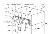
- 1 is a perspective view of an internal combustion engine to which an intake structure for an internal combustion engine according to an embodiment is applied, as seen obliquely from the front of a vehicle.
- FIG. 2 is a sectional view taken along the line AA of FIG. 1.
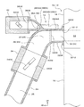
- FIG. 2 is a sectional view taken along line BB of FIG. 1. It is the perspective view which looked at the opening of the elongate passage part of the intake manifold from the slanting lower part.
- the engine 10 includes an engine body 12, an intake manifold 14, an exhaust manifold, and an exhaust gas recirculation device.
- the engine body 12 includes a cylinder block 16 and a cylinder head 18.
- a cylinder 20 (cylinder chamber) (see FIG. 3) that houses a piston is formed in the cylinder block 16.
- the combustion chamber of each cylinder 20 is formed in the cylinder head 18.
- the four cylinders 20 are linearly arranged along the vehicle width direction with the first cylinder 201, the second cylinder 202, the third cylinder 203, and the fourth cylinder 204.
- the intake manifold 14 is arranged on one side of the cylinder head 18 in a direction orthogonal to the direction in which the cylinders 20 are arranged.
- the exhaust manifold is arranged on the other side of the cylinder head 18. As shown in FIGS. 3 and 4, the intake manifold 14 connects the intake port 22 of the cylinder head 18 and the intake pipe 24.
- the exhaust manifold connects the exhaust port of the cylinder head 18 and the exhaust pipe.
- the intake passage for supplying fresh air to each cylinder 20 includes an intake passage portion of the intake pipe 24, an intake passage portion 26 of the intake manifold 14, and an intake port 22 of the cylinder head 18.
- the intake passage portion 26 of the intake manifold 14 has a vertical passage portion 28, a curved passage portion 30, and an elongated passage portion 32.
- the vertical passage portion 28 is located on the upstream side of the flow of intake air in the intake passage portion 26 and extends in the vertical direction.
- a throttle valve 34 is provided at the lower end of the vertical passage portion 28. The intake amount is adjusted by opening and closing the valve body 3402 of the throttle valve 34. That is, as shown in FIG.
- the intake passage portion of the intake pipe 24 constitutes an introduction passage 25 for introducing intake air into the intake manifold 14.
- the introduction passage 25 is connected to the lower end of the vertical passage portion 28 via the throttle valve 34, and in the present embodiment, the passage portion of the throttle valve 34 is connected to the intake manifold 14 from below the intake manifold 14.
- a first connection hole 2502 to be connected is configured.
- the elongated passage portion 32 is located on the downstream side of the intake air flow in the intake passage portion 26, extends along the arrangement direction of the cylinders 20, and has an elongated shape. In the present embodiment, the elongated passage portion 32 extends in the vehicle width direction.
- the elongated passage portion 32 includes an upper wall 3202 and a lower wall 3204 facing each other in the up-down direction, a pair of end surface walls 3206 facing each other in the longitudinal direction of the elongated passage portion 32, and the upper wall 3202 opposite to the cylinder head 18. , A lower wall 3204, and a back wall 3208 that connects the end portions of the pair of end surface walls 3206.
- the curved passage portion 30 is provided in a convex shape obliquely upward and connects the upper end of the vertical passage portion 28 and the central portion in the longitudinal direction of the elongated passage portion 32.
- the wall portion 3002 forming the curved passage portion 30 is connected to the upper wall 3202, the lower wall 3204, and the rear wall 3208.
- the exhaust gas recirculation device 36 recirculates the exhaust gas discharged from the combustion chamber as exhaust gas recirculation gas to the intake manifold 14 via the exhaust gas recirculation passage 38.
- a location 38 ⁇ / b> A located downstream of the flow of the exhaust gas recirculation gas in the exhaust gas recirculation passage 38 is integrally provided on the outer wall of the intake manifold 14.
- the location 38A located on the downstream side includes an upper flow path 3802 located on the upstream side of the flow of the exhaust gas recirculation gas, and an exhaust gas recirculation distribution unit 3804 provided on the downstream side of the upper flow path 3802.
- the exhaust gas recirculation distribution section 3804 has a branch section 3804A provided at the downstream end of the upper flow path 3802, and a plurality of branch passages 3804B connecting the branch section 3804A and the inside of the intake manifold 14.
- the exhaust gas recirculation distribution unit 3804 having such a configuration is integrally provided on the outer wall of the intake manifold 14.
- the branch passage 3804B connects the branch portion 3804A and the elongated passage portion 32.
- the branch portion 3804A is a portion where the exhaust recirculation gas passage is branched from a single passage to a plurality of passages.
- An exhaust gas recirculation valve 40 is provided at the upstream end of the flow of the exhaust gas recirculation gas in the upper flow path 3802.
- reference numeral 3805 indicates the upstream end of one of the two branch passages 3804B.
- the exhaust gas recirculation valve 40 adjusts the gas flow rate (recirculation amount) of the exhaust gas recirculation gas introduced into the intake manifold 14 by opening and closing the valve body 4002.
- the branch passage 3804B is connected from above the intake manifold 14 to the second and third connection holes 3806A and 3806B that are connected to the elongated passage portion 32.
- the exhaust gas recirculation gas is supplied to the elongated passage portion 32 from the connection holes 3806A and 3806B.
- the first connection hole 2502 is located between the second and third connection holes 3806A and 3806B when seen in a plan view.
- the first connection hole 2502 is connected to the intake manifold 14 on the upstream side of the intake flow with respect to the second and third connection holes 3806A and 3806B.
- the second and third connection holes 3806A, 3806B are provided at locations spaced in the longitudinal direction of the elongated passage portion 32, and face the location of the elongated passage portion 32 located outside the curved passage portion 30. ing. Specifically, the second and third connection holes 3806A and 3806B are provided on the upper wall 3202 on both sides of the center of the elongated passage portion 32 in the longitudinal direction, and are located on the outside of the curved passage portion 30. It faces the portion 3204. In the present embodiment, as shown in FIG.
- the elongated passage portion 32 is communicated with and the first cylinder 201, the second cylinder 202, the third cylinder 203, and the fourth cylinder 204 are arranged in the longitudinal direction of the elongated passage portion 32.
- Four intake ports 22 of a first intake port 221, a second intake port 222, a third intake port 223, and a fourth intake port 224 are provided corresponding to each, and the second and third connection holes 3806A, 3806B are Between the intake ports 22 of the two central cylinders 20 and the intake ports 22 outside the cylinders 20 are located closer to the intake ports 22 of the two central cylinders 20.
- the branch portion 3804A includes the second cylinder 202 and the third cylinder (second cylinder intake air).
- the branch passage 3804B is disposed in the middle of the opening of the port 222 and the opening of the third cylinder intake port 223.
- the branch passage 3804B extends from the branch portion 3804A toward the opening of the first cylinder intake port 221 and the opening of the fourth cylinder intake port 224, respectively. It extends and is arranged on both sides of a line connecting the second intake port 222 and the middle of the opening of the third intake port 223.
- the second connection hole 3806A is located between the first intake port 221 and the second intake port 222 and closer to the second intake port 222.
- the third connection hole 3806B is located between the third intake port 223 and the fourth intake port 224 and closer to the third intake port 223.
- the branch passage 3804B is line-symmetric with respect to a line connecting the branch portion 3804A and the middle of the second cylinder 202 and the third cylinder (the opening of the second cylinder intake port 222 and the opening of the third cylinder intake port 223). It is located in.
- the exhaust gas recirculation gas introduced from the upper flow path 3802 into each branch passage 3804B merges with the fresh air that spreads along the longitudinal direction of the elongated passage portion 32 from the second and third connection holes 3806A, 3806B. It is mixed with air and distributed to each intake port 22. At this time, the exhaust gas recirculation gas is supplied to the fresh air flowing along the longitudinal direction of the elongated passage portion 32 from the places spaced apart in the longitudinal direction of the elongated passage portion 32.
- the exhaust gas recirculation gas is recirculated to the intake manifold 14 via the respective branch passages 3804B, the variation in the amount of the exhaust gas recirculation gas supplied to each cylinder 20 is reduced, and the combustion stability of each cylinder 20 is improved. .. Further, as compared with the case where there is a single exhaust gas recirculation passage through which the exhaust gas recirculation gas is recirculated to the intake manifold 14, the amount of the exhaust gas recirculation gas that is efficiently mixed with the exhaust gas recirculation gas and is supplied to each cylinder 20. Variation is reduced, and combustion stability of each cylinder 20 is improved.
- the exhaust gas recirculation gas is supplied to the intake air flows in the two directions that flow from the central portion in the longitudinal direction of the elongated passage portion 32 to both sides.
- the exhaust gas recirculation gas is discharged from the second and third connection holes 3806A, 3806B for each flow of intake air having a different flow direction in the intake passage portion 26 (elongate passage portion 32) having a plurality of intake air flows having different flow directions. Supplied. Therefore, the exhaust gas recirculation gas and the fresh air are efficiently mixed, the variation in the amount of the exhaust gas recirculation gas supplied to each cylinder 20 is reduced, and the combustion stability of each cylinder 20 is improved.
- each branch passage 3804B arranged downstream of the exhaust gas recirculation valve 40 is formed integrally with the outer wall of the intake manifold 14. Therefore, the exhaust gas recirculation valve 40, which has a certain weight, is supported by the intake manifold 14 in a distributed manner through the wall portions forming the branch portion 3804A and the branch passages 3804B. As a result, the exhaust gas recirculation valve 40 is stably supported.
- the exhaust gas recirculation gas introduced into the intake manifold 14 through the second and third connection holes 3806A, 3806B contains water and is at a high temperature, whereas it is introduced through the first connection hole 2502 into the intake manifold 14.
- the fresh air discharged is at a lower temperature than the exhaust gas recirculation gas. Therefore, generally, when the exhaust gas recirculation gas is cooled by being mixed with fresh air and the water content of the exhaust gas recirculation gas is condensed to generate condensed water inside the intake manifold 14, a throttle valve 34 connected to a lower portion of the intake manifold 14 is formed. Condensed water may flow into the.
- the elongated passage portion 32 is connected to the upper end of the vertical passage portion 28 via the curved passage portion 30 that is convex upwards, and the second and third connection holes 3806A and 3806B of the branch passage 3804B are It faces the location of the elongated passage portion 32 located outside the curved passage portion 30. Therefore, the exhaust gas recirculation gas supplied from the second and third connection holes 3806A, 3806B is mixed with fresh air at the location outside the curved passage portion 30, so that the condensed water also becomes outside the curved passage portion 30. Occurs in.
- Such condensed water adheres to the portion of the lower wall 3204 located outside the curved passage portion 30, and the adhered condensed water is caused to flow from the curved passage portion 30 toward the intake port 22 by the flow of fresh air. Evaporate in each cylinder 20. Therefore, the condensed water does not flow inside the curved passage portion 30, so that the condensed water is suppressed from flowing into the throttle valve 34.
- the branch portion 3804A is arranged in the middle of the opening of the intake port 22 arranged in the cylinder head 18, and the branch passage 3804B is It is arranged so as to straddle a line connecting the branch portion 3804A and the middle of the opening of the intake port 22.
- the branch passage 3804B is arranged line-symmetrically with a line connecting the branch portion 3804A and the middle of the opening of the intake port 22 as the axis of symmetry. Therefore, the fresh air and the exhaust gas recirculation gas are efficiently mixed, and the exhaust gas recirculation gas is evenly distributed to the intake port 22. As a result, the combustion stability of each cylinder 20 is improved.
- the branch portion 3804A is arranged in the middle of the second cylinder 202 and the third cylinder 203 in the above embodiment, it is arranged in the middle of the first cylinder 201 and the second cylinder 202, or the middle of the third cylinder 203 and the fourth cylinder 204. You may arrange. In this case, it is preferable that the branch passage 3804B is not arranged in line symmetry, and the one extending to the opening of the intake port far from the branch portion 3804A may be lengthened. Further, although the above embodiment has been described with four cylinders, the same effect can be obtained with other numbers of cylinders.
- the branch portion 3804A may not be arranged in the middle of the cylinder, but may be aligned with the central cylinder, and the branch passage 3804B may be arranged line-symmetrically toward the outer intake port.
Landscapes
- Engineering & Computer Science (AREA)
- Chemical & Material Sciences (AREA)
- Combustion & Propulsion (AREA)
- Mechanical Engineering (AREA)
- General Engineering & Computer Science (AREA)
- Exhaust-Gas Circulating Devices (AREA)
Abstract
L'invention concerne une structure d'admission d'un moteur à combustion interne comportant un passage de recirculation d'échappement qui fait recirculer dans un collecteur d'admission du gaz évacué du moteur à combustion interne, et une soupape de recirculation d'échappement qui règle l'écoulement de gaz à travers le passage de recirculation d'échappement. Le passage de recirculation d'échappement est pourvu d'une unité de distribution de recirculation d'échappement qui comprend une partie de ramification se ramifiant en aval de la soupape de recirculation d'échappement et un passage de ramification reliant la partie de ramification et l'intérieur du collecteur d'admission. L'unité de distribution de recirculation d'échappement est formée d'un seul tenant avec la paroi externe du collecteur d'admission.
Priority Applications (2)
| Application Number | Priority Date | Filing Date | Title |
|---|---|---|---|
| PH1/2021/550955A PH12021550955B1 (en) | 2018-11-06 | 2019-11-06 | Intake structure of internal combustion engine |
| JP2020555560A JP7140204B2 (ja) | 2018-11-06 | 2019-11-06 | 内燃機関の吸気構造 |
Applications Claiming Priority (2)
| Application Number | Priority Date | Filing Date | Title |
|---|---|---|---|
| JP2018208560 | 2018-11-06 | ||
| JP2018-208560 | 2018-11-06 |
Publications (1)
| Publication Number | Publication Date |
|---|---|
| WO2020095965A1 true WO2020095965A1 (fr) | 2020-05-14 |
Family
ID=70612030
Family Applications (1)
| Application Number | Title | Priority Date | Filing Date |
|---|---|---|---|
| PCT/JP2019/043558 Ceased WO2020095965A1 (fr) | 2018-11-06 | 2019-11-06 | Structure d'admission de moteur à combustion interne |
Country Status (3)
| Country | Link |
|---|---|
| JP (1) | JP7140204B2 (fr) |
| PH (1) | PH12021550955B1 (fr) |
| WO (1) | WO2020095965A1 (fr) |
Cited By (2)
| Publication number | Priority date | Publication date | Assignee | Title |
|---|---|---|---|---|
| CN112664370A (zh) * | 2020-12-31 | 2021-04-16 | 天津特瑞捷动力科技有限公司 | 一种集成egr进气结构的进气歧管及含其的发动机 |
| CN117627827A (zh) * | 2022-08-25 | 2024-03-01 | 通用汽车环球科技运作有限责任公司 | 对进气歧管流道的车辆气体分配 |
Citations (2)
| Publication number | Priority date | Publication date | Assignee | Title |
|---|---|---|---|---|
| JPH01157265U (fr) * | 1988-04-20 | 1989-10-30 | ||
| JP2011247178A (ja) * | 2010-05-27 | 2011-12-08 | Aisin Seiki Co Ltd | インテークマニホールド |
-
2019
- 2019-11-06 PH PH1/2021/550955A patent/PH12021550955B1/en unknown
- 2019-11-06 JP JP2020555560A patent/JP7140204B2/ja active Active
- 2019-11-06 WO PCT/JP2019/043558 patent/WO2020095965A1/fr not_active Ceased
Patent Citations (2)
| Publication number | Priority date | Publication date | Assignee | Title |
|---|---|---|---|---|
| JPH01157265U (fr) * | 1988-04-20 | 1989-10-30 | ||
| JP2011247178A (ja) * | 2010-05-27 | 2011-12-08 | Aisin Seiki Co Ltd | インテークマニホールド |
Cited By (2)
| Publication number | Priority date | Publication date | Assignee | Title |
|---|---|---|---|---|
| CN112664370A (zh) * | 2020-12-31 | 2021-04-16 | 天津特瑞捷动力科技有限公司 | 一种集成egr进气结构的进气歧管及含其的发动机 |
| CN117627827A (zh) * | 2022-08-25 | 2024-03-01 | 通用汽车环球科技运作有限责任公司 | 对进气歧管流道的车辆气体分配 |
Also Published As
| Publication number | Publication date |
|---|---|
| PH12021550955B1 (en) | 2024-06-21 |
| PH12021550955A1 (en) | 2022-05-02 |
| JP7140204B2 (ja) | 2022-09-21 |
| JPWO2020095965A1 (ja) | 2021-09-02 |
Similar Documents
| Publication | Publication Date | Title |
|---|---|---|
| US9322364B2 (en) | Engine inlet for EGR-air flow distribution | |
| CN1605722B (zh) | 内燃机上的进气装置 | |
| US10359007B2 (en) | Intake apparatus for internal combustion engine and outside gas distribution structure for internal combustion engine | |
| US10550804B2 (en) | Air intake apparatus of multi-cylinder engine having secondary gas inlet passage connected to intake air inlet passage | |
| US8051843B2 (en) | Structure for introducing gas into intake air | |
| JP4923036B2 (ja) | 内燃機関の排気ガス再循環装置 | |
| CN108661829B (zh) | 排气再循环装置 | |
| US10731607B2 (en) | Air intake apparatus for internal combustion engine | |
| US7328692B2 (en) | Intake device for internal combustion engine | |
| KR20050101895A (ko) | Egr 시스템의 egr 챔버 | |
| US10107229B2 (en) | Cylinder head and internal combustion engine | |
| US7036493B1 (en) | Intake manifold for an internal combustion engine | |
| JP7140204B2 (ja) | 内燃機関の吸気構造 | |
| KR102644422B1 (ko) | 차량의 흡기 시스템 | |
| CN107178445B (zh) | 气体回流装置 | |
| US10598073B2 (en) | Exhaust system of internal combustion engine | |
| JP7140205B2 (ja) | 内燃機関の吸気構造 | |
| JPH0263092B2 (fr) | ||
| JP3547917B2 (ja) | 4気筒内燃機関の排ガス再循環装置 | |
| JP2015068190A (ja) | 車両用エンジンの吸気マニホールド構造 | |
| JP7131309B2 (ja) | 内燃機関の吸気構造 | |
| JP7404993B2 (ja) | エンジンの添加ガス供給装置 | |
| JP4285900B2 (ja) | 内燃機関のシリンダヘッド構造 | |
| JP6779222B2 (ja) | エンジンのための補助空気アセンブリ | |
| JP6534766B1 (ja) | 吸気マニホールド |
Legal Events
| Date | Code | Title | Description |
|---|---|---|---|
| 121 | Ep: the epo has been informed by wipo that ep was designated in this application |
Ref document number: 19882600 Country of ref document: EP Kind code of ref document: A1 |
|
| ENP | Entry into the national phase |
Ref document number: 2020555560 Country of ref document: JP Kind code of ref document: A |
|
| NENP | Non-entry into the national phase |
Ref country code: DE |
|
| 122 | Ep: pct application non-entry in european phase |
Ref document number: 19882600 Country of ref document: EP Kind code of ref document: A1 |