WO2020100411A1 - Dispositif de direction de véhicule - Google Patents
Dispositif de direction de véhicule Download PDFInfo
- Publication number
- WO2020100411A1 WO2020100411A1 PCT/JP2019/036298 JP2019036298W WO2020100411A1 WO 2020100411 A1 WO2020100411 A1 WO 2020100411A1 JP 2019036298 W JP2019036298 W JP 2019036298W WO 2020100411 A1 WO2020100411 A1 WO 2020100411A1
- Authority
- WO
- WIPO (PCT)
- Prior art keywords
- steering
- unit
- torque
- angle
- target
- Prior art date
- Legal status (The legal status is an assumption and is not a legal conclusion. Google has not performed a legal analysis and makes no representation as to the accuracy of the status listed.)
- Ceased
Links
Images








Classifications
-
- B—PERFORMING OPERATIONS; TRANSPORTING
- B62—LAND VEHICLES FOR TRAVELLING OTHERWISE THAN ON RAILS
- B62D—MOTOR VEHICLES; TRAILERS
- B62D5/00—Power-assisted or power-driven steering
- B62D5/04—Power-assisted or power-driven steering electrical, e.g. using an electric servo-motor connected to, or forming part of, the steering gear
-
- B—PERFORMING OPERATIONS; TRANSPORTING
- B62—LAND VEHICLES FOR TRAVELLING OTHERWISE THAN ON RAILS
- B62D—MOTOR VEHICLES; TRAILERS
- B62D6/00—Arrangements for automatically controlling steering depending on driving conditions sensed and responded to, e.g. control circuits
Definitions
- the present invention relates to a high-performance vehicle steering system that realizes a desired steering torque based on the torsion angle of a torsion bar or the like, is not affected by the state of the road surface, and is not affected by changes in mechanical system characteristics over time.
- An electric power steering device which is one of vehicle steering devices, applies an assist force (steering assist force) to a steering system of a vehicle by a rotational force of a motor, and uses electric power supplied from an inverter.
- the drive force of the controlled motor is applied as an assist force to the steering shaft or the rack shaft by the transmission mechanism including the speed reduction mechanism.
- Such a conventional electric power steering device performs feedback control of the motor current in order to accurately generate the assist force.
- the feedback control adjusts the motor applied voltage so that the difference between the steering assist command value (current command value) and the detected motor current value becomes small.
- the motor applied voltage is generally adjusted by PWM (pulse width). Modulation) control duty is adjusted.
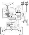
- the column shaft (steering shaft, handle shaft) 2 of the steering wheel 1 includes a speed reduction mechanism 3, universal joints 4a and 4b, a pinion rack mechanism 5, a tie rod 6a, 6b, and further connected to steering wheels 8L, 8R via hub units 7a, 7b. Further, the column shaft 2 having a torsion bar is provided with a torque sensor 10 for detecting a steering torque Ts of the steering wheel 1 and a steering angle sensor 14 for detecting a steering angle ⁇ h, and a motor for assisting the steering force of the steering wheel 1 is provided. 20 is connected to the column shaft 2 via the reduction mechanism 3.
- Electric power is supplied from the battery 13 to the control unit (ECU) 30 that controls the electric power steering device, and an ignition key signal is input via the ignition key 11.
- the control unit 30 calculates the current command value of the assist (steering assistance) command based on the steering torque Ts detected by the torque sensor 10 and the vehicle speed Vs detected by the vehicle speed sensor 12, and compensates for the current command value.
- the current supplied to the EPS motor 20 is controlled by the applied voltage control command value Vref.
- a CAN (Controller Area Network) 40 that exchanges various vehicle information is connected to the control unit 30, and the vehicle speed Vs can also be received from the CAN 40.
- the control unit 30 can also be connected to a non-CAN 41 other than the CAN 40 that exchanges communication, analog / digital signals, radio waves, and the like.
- the control unit 30 is mainly composed of a CPU (including MCU, MPU, etc.), and a general function executed by a program inside the CPU is shown in FIG.
- the function and operation of the control unit 30 will be described with reference to FIG. 2.
- the steering torque Ts detected by the torque sensor 10 and the vehicle speed Vs detected by the vehicle speed sensor 12 (or from the CAN 40) are the current command value calculation unit. 31 is input.
- the current command value calculation unit 31 calculates the current command value Iref1 which is the control target value of the current supplied to the motor 20, using the assist map and the like based on the input steering torque Ts and vehicle speed Vs.
- the voltage control command value Vref whose characteristics have been improved by the PI control unit 35 is input to the PWM control unit 36, and the motor 20 is PWM-driven via the inverter 37 as a drive unit.
- the current value Im of the motor 20 is detected by the motor current detector 38 and fed back to the subtraction unit 32B.
- the compensating signal CM from the compensating signal generating unit 34 is added to the adding unit 32A, and the characteristic of the steering system system is compensated by adding the compensating signal CM to improve the convergence and the inertia characteristic. ..
- the compensation signal generation unit 34 adds the self-aligning torque (SAT) 343 and the inertia 342 by the addition unit 344, further adds the convergence 341 to the addition result by the addition unit 345, and compensates the addition result by the addition unit 345. It is a signal CM.
- the steering torque applied by the driver's manual input is detected by the torque sensor as the torsion torque of the torsion bar, and the assist current corresponding to the torque is mainly detected. Is controlling the motor current.
- the steering torque may be different depending on the steering angle due to the difference in the road surface state (for example, inclination). Steering torque may also be affected by variations in motor output characteristics over time.
- Patent Document 1 an electric power steering device as disclosed in Japanese Patent No. 5208894 (Patent Document 1) has been proposed.
- the steering angle or the steering torque is determined based on the relationship between the steering angle or the steering torque and the response amount.
- the target value of the steering torque is set based on the relationship (steering reaction force characteristic map).
- the steering reaction force characteristic map must be obtained in advance, and the control is performed based on the deviation between the target value of the steering torque and the detected steering torque. Therefore, the influence on the steering torque may remain.
- the steering wheel may stop halfway without returning to the on-center, which may result in poor fit.
- a solution is also desired.
- the present invention has been made under the circumstances as described above, and an object of the present invention is not affected by the condition of the road surface, is not affected by the change in the mechanical characteristics of the steering system due to aging, and is effective for the steering angle and the like. It is an object of the present invention to provide a vehicle steering system capable of easily achieving an equivalent steering torque. Further, it is also an object to be able to return the handle after releasing it to the vicinity of the center.
- the present invention relates to a steering device for a vehicle, which includes at least a torsion bar having an arbitrary spring constant and a sensor for detecting a torsion angle of the torsion bar, and which assist-controls a steering system by driving and controlling a motor.
- the object of the above is to provide a target steering torque generator that generates a target steering torque, a converter that converts the target steering torque into a target twist angle, and a motor current that causes the twist angle to follow the target twist angle.
- a steering wheel return compensating section for calculating a first torque signal for compensating the steering wheel returning based on the steering torque and the first angular velocity information. It is achieved by outputting the first torque signal as the target steering torque and controlling the drive of the motor based on the motor current command value.
- the steering wheel return compensator uses a torque sensitive gain map to obtain a torque sensitive gain based on the magnitude of the steering torque, and a speed sensitive gain map.
- a speed sensitive gain unit that obtains a speed sensitive gain based on the magnitude of the first angular velocity information, and calculates the first torque signal from the torque sensitive gain, the speed sensitive gain, and the sign of the first angular velocity information.
- the torque-sensitive gain map has a characteristic that the torque-sensitive gain decreases as the steering torque increases, or the speed-sensitive gain map includes the first angular velocity information.
- the velocity sensitive gain increases as the magnitude of the first angular velocity information increases, and when the magnitude of the first angular velocity information exceeds the predetermined value, the The steering wheel return compensating unit further includes a limiting unit that limits the upper and lower limit values of the first torque signal by having a characteristic that the velocity sensitive gain decreases as the magnitude of the first angular velocity information increases.
- the target steering torque generation unit uses the basic map to obtain the second torque signal from the steering angle and the vehicle speed, and the damper gain map that is a vehicle speed response to obtain the second angular velocity information.
- the present invention further includes a damper calculation unit that obtains a third torque signal based on the steering state and the steering angle, and a hysteresis correction unit that obtains a fourth torque signal by performing hysteresis correction using the steering state and the steering angle.
- a target steering torque generation unit further includes a phase compensating unit that performs phase compensation in a front stage or a rear stage of the basic map unit, and the steering wheel is provided via the basic map unit and the phase compensating unit. This is achieved more effectively by obtaining the second torque signal from the angle and the vehicle speed.
- the twist angle follows the target twist angle by controlling the target twist angle obtained based on the target steering torque generated by the target steering torque generation unit.
- a desired steering torque can be realized, and an appropriate steering torque based on the driver's feeling of steering can be applied.
- the handle can be returned to the vicinity of the center when the handle is turned off and then released.
- FIG. 3 is a block diagram showing a configuration example (first embodiment) of a target steering torque generation unit. It is a diagram which shows the characteristic example of a basic map. It is a diagram which shows the characteristic example of a damper gain map. It is a diagram which shows the characteristic example of a hysteresis correction part. It is a block diagram showing an example of composition of a handle return compensation part.
- FIG. 5 is a flowchart showing an operation example (first embodiment) of the present invention.
- 6 is a flowchart showing an operation example (first embodiment) of a target steering torque generation unit. It is a flow chart which shows an example of operation of a twist angle control part. 6 is a graph showing an example of a time response of a steering angle and a steering torque when there is no steering wheel return compensation in a simulation showing an effect of a steering wheel return compensation unit.
- FIG. 6 is a graph showing an example of a time response of a steering angle and a steering torque when steering wheel return compensation is performed in a simulation showing an effect of a steering wheel return compensation unit.
- It is a block diagram which shows the structural example (2nd Embodiment) of a target steering torque production
- the present invention is a steering apparatus for a vehicle for realizing an equivalent steering torque with respect to a steering angle or the like without being affected by the state of the road surface, and a torsion angle of a torsion bar or the like is set to a value corresponding to the steering angle or the like.
- the desired steering torque is realized by controlling so as to follow.
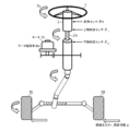
- FIG. 3 is a diagram showing an installation example of the EPS steering system and various sensors, and the column shaft 2 is provided with a torsion bar 2A.
- Road surface reaction force Fr and road surface information ⁇ act on the steered wheels 8L and 8R.
- An upper angle sensor is provided on the handle side of the column shaft 2 with the torsion bar 2A interposed therebetween, and a lower angle sensor is provided on the steering wheel side of the column shaft 2 with the torsion bar 2A interposed therebetween. Detects the steering wheel angle ⁇ 1 , and the lower angle sensor detects the column angle ⁇ 2 .
- the steering angle ⁇ h is detected by a steering angle sensor provided above the column shaft 2, and the twist angle ⁇ and the torsion bar torque of the torsion bar are calculated from the deviations of the steering wheel angle ⁇ 1 and the column angle ⁇ 2 according to the following formulas 1 and 2.
- Tt can be calculated.
- Kt is the spring constant of the torsion bar 2A.
- the torsion bar torque Tt can also be detected by using a torque sensor disclosed in JP 2008-216172 A, for example.
- the torsion bar torque Tt is also treated as the steering torque Ts.
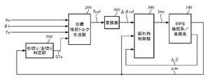
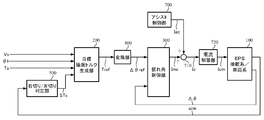
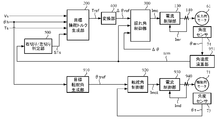
- FIG. 4 is a block diagram showing a configuration example (first embodiment) of the present invention, in which steering of a driver's steering wheel is assist-controlled by a motor in the EPS steering system / vehicle system 100.
- the target steering torque generation unit 200 that outputs the target steering torque Tref includes the vehicle speed Vs, the steering torque Ts, and the right-turn or left-turn steering state output from the right-turn / left-turn determination unit 500. STs is input.
- the target steering torque Tref is converted into a target twist angle ⁇ ref by the conversion unit 400, and the target twist angle ⁇ ref is input to the twist angle control unit 300 together with the twist angle ⁇ of the torsion bar 2A and the motor angular velocity ⁇ m.
- the twist angle control unit 300 calculates a motor current command value Imc such that the twist angle ⁇ becomes the target twist angle ⁇ ref, and the motor of the EPS is driven by the motor current command value Imc.
- the right-turn / left-turn determination unit 500 determines whether the steering is right-turn or left-turn based on the motor angular velocity ⁇ m, and outputs the determination result as the steering state STs. That is, when the motor angular velocity ⁇ m has a positive value, it is determined to be “right cut”, and when the motor angular velocity ⁇ m has a negative value, it is determined to be “left cut”. Instead of the motor angular velocity ⁇ m, an angular velocity calculated by performing a velocity calculation on the steering angle ⁇ h, the steering wheel angle ⁇ 1 or the column angle ⁇ 2 may be used.
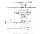
- FIG. 5 shows a configuration example of the target steering torque generation unit 200.
- the target steering torque generation unit 200 includes a basic map unit 210, a differentiation unit 220, a damper gain unit 230, a hysteresis correction unit 240, a steering wheel return compensation unit 250, and a multiplication.
- the steering angle ⁇ h is input to the basic map unit 210, the differentiation unit 220, the hysteresis correction unit 240, and the steering wheel return compensation unit 250, and output from the right-turn / left-turn determination unit 500.
- the steering state STs is input to the hysteresis correction unit 240, the steering torque Ts is input to the steering wheel return compensation unit 250, and the vehicle speed Vs is input to the basic map unit 210 and the damper gain unit 230.
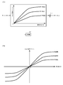
- the basic map unit 210 has a basic map and outputs a torque signal (second torque signal) Tref_a with the vehicle speed Vs as a parameter using the basic map.
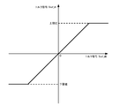
- the basic map is adjusted by tuning. For example, as shown in FIG. 6A, the torque signal Tref_a increases as the magnitude (absolute value)
- the torque signal Tref_a is calculated by multiplying the calculated value by the sign of the steering angle ⁇ h.
- a map may be formed according to the positive and negative steering angles ⁇ h.
- the mode of change may be changed depending on whether the steering angle ⁇ h is positive or negative.
- the basic map shown in FIG. 6 is sensitive to vehicle speed, it may not be sensitive to vehicle speed.
- the differentiator 220 differentiates the steering angle ⁇ h to calculate the steering angular velocity ⁇ h that is the angular velocity information (second angular velocity information), and the steering angular velocity ⁇ h is input to the multiplier 270.
- the damper gain unit 230 outputs a damper gain D G by which the steering angular velocity ⁇ h is multiplied.
- the multiplication result of the steering angular velocity ⁇ h and the damper gain D G in the multiplication unit 270 is input to the addition unit 272 as a torque signal (third torque signal) Tref_b.
- the damper gain D G is obtained according to the vehicle speed Vs using the vehicle speed sensitive damper gain map included in the damper gain unit 230.
- the damper gain map has a characteristic of gradually increasing as the vehicle speed Vs increases, as shown in FIG. 7, for example.
- the damper gain map may be variable according to the steering angle ⁇ h.
- the damper gain unit 230 and the multiplication unit 270 form a damper calculation unit.
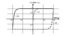
- the hysteresis correction unit 240 calculates the torque signal (fourth torque signal) Tref_c according to the following Expression 3 based on the steering angle ⁇ h and the steering state STs.
- x ⁇ h
- y Tref_c
- a> 1 c>
- a hys is a hysteresis width.
- the above formula 4 can be derived by substituting x1 for x and y1 for y R and y L in the above formula 3.
- An example diagram of the generated torque signal Tref_c is shown in FIG. That is, the torque signal Tref_c from the hysteresis correction unit 240 has hysteresis characteristics such as 0 origin ⁇ L1 (thin line) ⁇ L2 (broken line) ⁇ L3 (thick line).
- the coefficient A hys that represents the output width of the hysteresis characteristic and the coefficient c that represents roundness may be variable according to the vehicle speed Vs and / or the steering angle ⁇ h.
- the steering wheel return compensator 250 calculates a torque signal (first torque signal) Tref_d for compensating the steering wheel return.
- first torque signal first torque signal
- FIG. 9 shows a configuration example of the handle return compensation unit 250.
- the handle return compensation unit 250 includes a differentiating unit 251, absolute value units 252 and 253, a torque sensitive gain unit 254, a speed sensitive gain unit 255, a coding unit 256, multiplying units 260 and 261, a limiting unit 257, a filter unit 258, and a sign reversing unit.
- the unit 259 is provided.
- the differentiating part 251 differentiates the steering angle ⁇ h to calculate the steering angular speed ⁇ h1 which is the angular speed information (first angular speed information).
- the differentiating unit 220 may be shared and the differentiating unit 251 may be omitted.
- the absolute value units 252 and 253 output the magnitude (absolute value) of the input data.
- the absolute value unit 252 outputs the absolute value of the steering torque Ts, and the absolute value unit 253 outputs the absolute value of the steering angular velocity ⁇ h1. ..
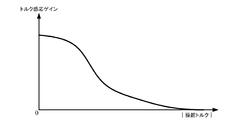
- the torque sensitive gain unit 254 obtains the torque sensitive gain Gt according to the absolute value of the steering torque Ts using the torque sensitive gain map.
- the torque sensitive gain map has a characteristic that the torque sensitive gain Gt gradually decreases as the absolute value of the steering torque Ts increases, as shown in FIG. 10, for example.
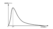
- the speed sensitive gain unit 255 obtains the speed sensitive gain Gv according to the absolute value of the steering angular speed ⁇ h1 using the speed sensitive gain map.
- the speed-sensitive gain map shows that the speed-sensitive gain Gv increases rapidly as the absolute value of the steering angular speed ⁇ h1 increases in the range of the absolute value of the steering angular speed ⁇ h1 from 0 to a predetermined value ⁇ 0.
- the steering angle velocity ⁇ h1 gradually decreases as the absolute value of the steering angular velocity ⁇ h1 increases.
- the sign unit 256 outputs the sign (+1, -1) of the steering angular velocity ⁇ h1.
- the limiting unit 257 limits the upper and lower limit values of the torque signal Tref_d0 calculated by multiplying the torque sensitive gain Gt, the speed sensitive gain Gv, and the sign of the steering angular velocity ⁇ h1, and outputs the torque signal Tref_d1.
- the upper limit value and the lower limit value for the torque signal are set in advance, and when the input torque signal Tref_d0 is the upper limit value or more, the upper limit value is set, and when the input torque signal Tref_d0 is the lower limit value or less, the lower limit value is set otherwise. In the case of, the torque signal Tref_d0 is output as the torque signal Tref_d1.
- the filter unit 258 reduces the high-frequency noise component included in the torque signal Tref_d1 by the filtering process using the low-pass filter (LPF), and outputs it as the torque signal Tref_d2.
- LPF low-pass filter
- the sign inversion unit 259 inverts the sign of the torque signal Tref_d2 and outputs it as the torque signal Tref_d.
- the characteristics of the torque sensitive gain map and the speed sensitive gain map are not limited to the curved characteristics shown in FIGS. 10 and 11, and may be linear characteristics or may be defined by a function.
- the limiting unit 257 can be omitted when the torque signal does not become an abnormal value, or when the output of the abnormal value is suppressed by other means, and when the high frequency noise is not superimposed on the torque signal or by other means.
- the filter unit 258 can be omitted when reducing high frequency noise.
- the torque signals Tref_d, Tref_c, Tref_b, and Tref_a obtained as described above are sequentially added by the adders 273, 272, and 271, and the final addition result is output as the target steering torque Tref.
- the steering angular velocities ⁇ h and ⁇ h1 calculated by the differentiating units 220 and 251 are obtained by a differential calculation with respect to the steering angle ⁇ h, but even if the LPF process is appropriately performed to reduce the influence of noise in the high range. Good (with respect to the steering angular velocity ⁇ h1 calculated by the differentiating unit 251, the LPF process does not have to be performed if the high-frequency noise reduction can be handled by the filter unit 258). Further, the differential calculation and the LPF processing may be performed using a high pass filter (HPF) and a gain.
- HPF high pass filter
- the steering angular velocities ⁇ h and ⁇ h1 are calculated not by the steering angle ⁇ h but by performing a differential calculation and LPF processing on the steering wheel angle ⁇ 1 detected by the upper angle sensor or the column angle ⁇ 2 detected by the lower angle sensor. You may. Instead of the steering angular velocities ⁇ h and ⁇ h1, the motor angular velocity ⁇ m may be used as the angular velocity information, and in this case, the differentiating units 220 and 251 are unnecessary.
- the conversion unit 400 has a characteristic of ⁇ 1 / Kt in which the sign of the reciprocal of the spring constant Kt of the torsion bar 2A is inverted, and converts the target steering torque Tref into the target twist angle ⁇ ref.
- the twist angle control unit 300 calculates the motor current command value Imc based on the target twist angle ⁇ ref, the twist angle ⁇ , and the motor angular velocity ⁇ m.
- FIG. 13 is a block diagram showing a configuration example of the torsion angle control unit 300.
- the torsion angle control unit 300 includes a torsion angle feedback (FB) compensation unit 310, a torsion angular velocity calculation unit 320, a velocity control unit 330, and a stabilization compensation unit.
- 340, an output limiting unit 350, a subtracting unit 361, and an adding unit 362 are provided.
- the target twist angle ⁇ ref output from the converting unit 400 is input to the subtracting unit 361, and the twist angle ⁇ is input to the subtracting unit 361.
- the motor angular velocity ⁇ m is input to the stabilization compensator 340.
- the torsion angle FB compensation unit 310 multiplies the target torsion angle ⁇ ref and the deviation ⁇ 0 of the torsion angle ⁇ calculated by the subtraction unit 361 by a compensation value C FB (transfer function), and the target torsion angle ⁇ ref is twisted by the torsion angle ⁇ . Outputs a target torsional angular velocity ⁇ ref that follows.
- the compensation value C FB may be a simple gain Kpp or a commonly used compensation value such as a PI control compensation value.
- the target twist angular velocity ⁇ ref is input to the velocity control unit 330.
- the twist angle FB compensator 310 and the speed controller 330 allow the twist angle ⁇ to follow the target twist angle ⁇ ref to realize a desired steering torque.
- the torsional angular velocity calculation unit 320 calculates the torsional angular velocity ⁇ t by performing a differential calculation on the torsional angle ⁇ , and the torsional angular velocity ⁇ t is input to the velocity control unit 330. Pseudo-differentiation using HPF and gain may be performed as the differential operation. Further, the twist angular velocity ⁇ t may be calculated by other means or other than the twist angle ⁇ and input to the velocity control unit 330.
- the speed control unit 330 calculates the motor current command value Imca1 by the IP control (proportional PI control) so that the torsional angular velocity ⁇ t follows the target torsional angular velocity ⁇ ref.
- the subtraction unit 333 calculates a difference ( ⁇ ref ⁇ t) between the target torsional angular velocity ⁇ ref and the torsional angular velocity ⁇ t, the integration unit 331 having a gain Kvi integrates the difference, and the integration result is added and input to the subtraction unit 334. It The torsional angular velocity ⁇ t is also input to the proportional section 332, subjected to proportional processing by the gain Kvp, and subtracted and input to the subtraction section 334.
- the subtraction result of the subtraction unit 334 is output as the motor current command value Imca1.
- the speed control unit 330 is not the IP control but the PI control, the P (proportional) control, the PID (proportional integral derivative) control, the PI-D control (differential preceding PID control), the model matching control, the model reference.
- the motor current command value Imca1 may be calculated by a generally used control method such as control.
- the stabilization compensator 340 has a compensation value Cs (transfer function), and calculates the motor current command value Imca2 from the motor angular velocity ⁇ m. If the gains of the torsion angle FB compensator 310 and the speed controller 330 are increased in order to improve the followability and the disturbance characteristics, a controllable oscillation phenomenon in a high range will occur. As a countermeasure against this, a transfer function (Cs) necessary for stabilizing the motor angular velocity ⁇ m is set in the stabilization compensating unit 340. As a result, stabilization of the entire EPS control system can be realized.
- the transfer function (Cs) of the stabilization compensating unit 340 for example, a first-order filter represented by the following formula 7 is set, which is set by a pseudo-differential using a first-order HPF structure and a gain.
- K sta is a gain
- fc is a center frequency
- fc is set to 150 [Hz]
- s is a Laplace operator.
- a secondary filter, a quaternary filter, or the like may be used as the transfer function.
- the motor current command value Imca1 from the speed control unit 330 and the motor current command value Imca2 from the stabilization compensating unit 340 are added by the adding unit 362 and output as the motor current command value Imcb.
- the output limiter 350 limits the upper and lower limits of the motor current command value Imcb and outputs the motor current command value Imc. Similar to the limiting unit 257 in the steering wheel return compensating unit 250, the upper limit value and the lower limit value for the motor current command value Imcb are set in advance and limited.
- the stabilization compensator may be omitted.
- the output limiting unit can also be omitted.
- the right-turn / left-turn determination unit 500 inputs the motor angular velocity ⁇ m, determines whether the steering is right-turn or left-turn based on the sign of the motor angular velocity ⁇ m, and sets the determination result as the steering state STs. It is output to the target steering torque generation unit 200 (step S10).
- the target steering torque generator 200 inputs the steering angle ⁇ h, the steering torque Ts, and the vehicle speed Vs together with the steering state STs, and generates the target steering torque Tref (step S20).
- An operation example of the target steering torque generation unit 200 will be described with reference to the flowchart in FIG.
- the steering angle ⁇ h input to the target steering torque generation unit 200 is input to the basic map unit 210, the differentiation unit 220, the hysteresis correction unit 240 and the steering wheel return compensation unit 250, the steering state STs is input to the hysteresis correction unit 240, and the steering torque Ts is input to the steering wheel Ts.
- the vehicle speed Vs is input to the return compensating unit 250 and to the basic map unit 210 and the damper gain unit 230 (step S21).
- the basic map unit 210 uses the basic map shown in FIG. 6A or 6B to generate a torque signal Tref_a corresponding to the steering angle ⁇ h and the vehicle speed Vs and outputs it to the addition unit 271 (step S22). ).
- the differentiating unit 220 differentiates the steering angle ⁇ h and outputs the steering angular velocity ⁇ h (step S23), and the damper gain unit 230 outputs the damper gain D G according to the vehicle speed Vs using the damper gain map shown in FIG. 7 (step S23).
- the multiplication unit 270 multiplies the steering angular velocity ⁇ h and the damper gain D G to calculate the torque signal Tref_b, and outputs the torque signal Tref_b to the addition unit 272 (step S25).
- the hysteresis correction unit 240 performs the hysteresis correction by switching the calculation according to Formula 5 and Formula 6 according to the steering state STs with respect to the steering angle ⁇ h (step S26), generates the torque signal Tref_c, and adds it to the addition unit 273. Output (step S27). Note that the hysteresis widths A hys , c, x1, and y1 in Equations 5 and 6 are set and held in advance, but b and b ′ are calculated in advance from Equation 6 and b and b ′ are used instead of x1 and y1. May be held.
- the steering wheel return compensation unit 250 inputs the input steering torque Ts and steering angle ⁇ h to the absolute unit 252 and the differentiation unit 251, respectively, and the differentiation unit 251 differentiates the steering angle ⁇ h to calculate the steering angular velocity ⁇ h1 (step S28). ), And the steering angular velocity ⁇ h1 is input to the absolute value unit 253 and the encoding unit 256.
- the absolute value unit 252 calculates the absolute value of the steering torque Ts and outputs it to the torque sensitive gain unit 254, and the absolute value unit 253 calculates the absolute value of the steering angular velocity ⁇ h1 and outputs it to the speed sensitive gain unit 255 (step S29). ).
- the torque sensitive gain unit 254 determines the torque sensitive gain Gt according to the absolute value of the steering torque Ts by using the torque sensitive gain map having the characteristics shown in FIG. 10 (step S30).
- the speed sensitive gain unit 255 determines the speed sensitive gain Gv according to the absolute value of the steering angular speed ⁇ h1 by using the speed sensitive gain map having the characteristics shown in FIG. 11 (step S31).
- the torque sensitive gain Gt and the speed sensitive gain Gv are multiplied by the multiplication unit 260 (step S32), and the multiplication result is multiplied by the sign of the steering angular velocity ⁇ h1 obtained by the encoding unit 256 in the multiplication unit 261 (step S33).
- the torque signal Tref_d0 is output.
- the torque signal Tref_d0 is input to the limiting unit 257, and the limiting unit 257 limits the upper and lower limit values of the torque signal Tref_d0 by the preset upper limit value and lower limit value, and outputs the torque signal Tref_d1 to the filter unit 258 (step S34). ..
- the filter unit 258 performs a filtering process on the torque signal Tref_d1 and outputs it as the torque signal Tref_d2 to the sign inverting unit 259 (step S35).
- the sign inversion unit 259 outputs the torque signal Tref_d, which is the inversion of the sign of the torque signal Tref_d2, to the addition unit 273 (step S36).
- the addition unit 273 adds the torque signals Tref_c and Tref_d
- the addition unit 272 adds the torque signal Tref_b to the addition result
- the addition unit 271 adds the torque signal Tref_a to the addition result.
- the steering torque Tref is calculated (step S37).
- the target steering torque Tref generated by the target steering torque generation unit 200 is input to the conversion unit 400 and converted into the target twist angle ⁇ ref by the conversion unit 400 (step S40).
- the target twist angle ⁇ ref is input to the twist angle control unit 300.
- the torsion angle control unit 300 inputs the torsion angle ⁇ and the motor angular velocity ⁇ m together with the target torsion angle ⁇ ref, and calculates the motor current command value Imc (step S50).
- An operation example of the torsion angle control unit 300 will be described with reference to the flowchart of FIG.
- the target twist angle ⁇ ref input to the twist angle control unit 300 is input to the subtraction unit 361, the twist angle ⁇ is input to the subtraction unit 361 and the twist angular velocity calculation unit 320, and the motor angular velocity ⁇ m is input to the stabilization compensation unit 340 (step S51).
- the subtraction unit 361 calculates the deviation ⁇ 0 by subtracting the twist angle ⁇ from the target twist angle ⁇ ref (step S52).
- Deviation [Delta] [theta] 0 is input to the helix angle FB compensation unit 310, the twist angle FB compensation unit 310 compensates the deviation [Delta] [theta] 0 is multiplied by the compensation value C FB on the deviation [Delta] [theta] 0 (step S53), the target torsion angular velocity ⁇ ref Is output to the speed control unit 330.
- the torsional angular velocity calculation unit 320 which has received the torsional angle ⁇ , calculates the torsional angular velocity ⁇ t by a differential calculation with respect to the torsion angle ⁇ (step S54), and outputs it to the velocity control unit 330.
- the difference between the target torsional angular velocity ⁇ ref and the torsional angular velocity ⁇ t is calculated by the subtracting unit 333, and the difference is integrated (Kvi / s) by the integrating unit 331 and added to the subtracting unit 334 (step S55).
- the twisting angular velocity ⁇ t is proportionally processed (Kvp) by the proportional portion 332, the proportional result is subtracted and input to the subtracting portion 334 (step S55), and the motor current command value Imca1 which is the subtracting result of the subtracting portion 334 is output and added. It is input to the unit 362.
- the stabilization compensator 340 performs stabilization compensation on the input motor angular velocity ⁇ m using the transfer function Cs represented by Expression 7 (step S56), and the motor current command value Imca2 from the stabilization compensator 340 is obtained. Is input to the addition unit 362.
- the addition unit 362 adds the motor current command values Imca1 and Imca2 (step S57), and the addition result motor current command value Imcb is input to the output limiting unit 350.
- the output limiter 350 limits the upper and lower limit values of the motor current command value Imcb by the preset upper limit value and lower limit value (step S58), and outputs the motor current command value Imc (step S59).
- the motor is driven based on the motor current command value Imc output from the torsion angle control unit 300, and current control is performed (step S60).
- the steering angle ⁇ h starts to operate in a state of about 60 deg, and the steering wheel return compensation unit performs steering wheel return compensation with and without steering wheel return compensation part 2 seconds after the operation is started.
- the time response of the upper angle of the torsion bar), the target steering torque, and the steering torque (torsion bar torque) is simulated.
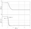
- FIG. 17 shows the simulation result when there is no steering wheel return compensation.
- 17A shows the time response of the steering angle
- FIG. 17B shows the time response of the target steering torque with a broken line and the time response of the steering torque with a solid line. From FIG. 17 (A), it can be seen that the steering angle is stopped at a position of about 17 deg after being released after 2 seconds from the start of the operation. This state is visually unpleasant to the driver and the vehicle deviates greatly from straight running, which is an unsuitable state in terms of safety.
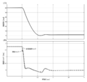
- FIG. 18 shows a simulation result in the case where there is steering wheel return compensation
- FIGS. 18A and 18B correspond to FIGS. 17A and 17B, respectively. From (A), it can be seen that the steering angle is improved to about 2 deg after the part is released. If improvements are made up to this point, it is possible to maintain a state similar to straight running, and the driver does not feel uncomfortable.
- the target steering torque generation unit 200 includes a basic map unit 210, a damper calculation unit (damper gain unit 230 and multiplication unit 270), a hysteresis correction unit 240, and a steering wheel return compensation unit 250. Only the handle return compensating section 250 may be specialized and only the handle return compensating section 250 may be provided.
- FIG. 19 shows a configuration example (second embodiment) of the target steering torque generation unit in this case.
- the torque signal Tref_d output from the steering wheel return compensation unit 250 is output as the target steering torque Tref.
- the target steering torque generation unit may be configured by combining at least one of the basic map unit 210, the damper calculation unit and the hysteresis correction unit 240, and the steering wheel return compensation unit 250.
- the motor current command value Imc output from the torsion angle control unit in the first and second embodiments is a current command value calculated based on the steering torque in the conventional EPS (hereinafter referred to as “assist current command value”). ) May be added to, for example, the current command value Iref1 output from the current command value calculation unit 31 shown in FIG. 2 or the current command value Iref2 obtained by adding the compensation signal CM to the current command value Iref1.
- FIG. 20 shows a configuration example (third embodiment) in which the above contents are applied to the first embodiment.
- the assist control unit 700 includes a current command value calculation unit 31, or a current command value calculation unit 31, a compensation signal generation unit 34, and an addition unit 32A.
- the assist current command value Iac output from the assist control unit 700 (corresponding to the current command value Iref1 or Iref2 in FIG. 2) and the motor current command value Imc output from the torsion angle control unit 300 are added by the addition unit 710.
- the current command value Ic that is the addition result is input to the current limiting unit 720, the motor is driven based on the current command value Icm in which the maximum current is limited, and the current control is performed.
- the phase compensating unit 280 that performs phase compensation may be inserted in the preceding stage or the subsequent stage of the basic map unit 210. That is, the configuration of the region R surrounded by the broken line in FIG. 5 may be configured as shown in FIG. 21 (A) or (B).
- the phase compensating unit 280 when phase lead compensation is set as the phase compensation and, for example, phase lead compensation is performed by a first-order filter with a numerator cutoff frequency of 1.0 Hz and a denominator cutoff frequency of 1.3 Hz, A refreshing feel can be realized.
- the target steering torque generation unit is not limited to the above configuration as long as it has a configuration based on the steering angle.
- the present invention is applied to a column type EPS, but the present invention is not limited to an upstream type such as a column type, but can also be applied to a downstream type EPS such as a rack and pinion.
- the feedback control based on the target twist angle can be applied to a steer-by-wire (SBW) reaction force device including at least a torsion bar (arbitrary spring constant) and a sensor for detecting a twist angle.
- SBW steer-by-wire
- An embodiment (fourth embodiment) in which the present invention is applied to an SBW reaction force device including a torsion bar will be described.
- FIG. 22 is a diagram showing a configuration example of the SBW system in correspondence with the general configuration of the electric power steering device shown in FIG. 1. The same components are designated by the same reference numerals, and detailed description will be omitted.
- the SBW system is a system that does not have an intermediate shaft mechanically coupled to the column shaft 2 by a universal joint 4a and transmits the operation of the steering wheel 1 to an steering mechanism including steering wheels 8L, 8R by an electric signal. ..
- the SBW system includes a reaction force device 60 and a drive device 70, and a control unit (ECU) 50 controls both devices.
- the reaction force device 60 detects the steering angle ⁇ h by the steering angle sensor 14, and at the same time transmits the motion state of the vehicle transmitted from the steered wheels 8L, 8R to the driver as reaction force torque.
- the reaction torque is generated by the reaction force motor 61.
- the SBW system to which the present invention is applied is a type having a torsion bar, and the torque sensor 10 detects the steering torque Ts. To do. Further, the angle sensor 74 detects the motor angle ⁇ m of the reaction force motor 61.
- the drive device 70 drives the drive motor 71 in accordance with the steering of the steering wheel 1 by the driver, applies the drive force to the pinion rack mechanism 5 via the gear 72, and operates it via the tie rods 6a and 6b. Steering wheels 8L and 8R are steered.
- An angle sensor 73 is arranged in the vicinity of the pinion rack mechanism 5 and detects the steering angle ⁇ t of the steered wheels 8L, 8R.
- the ECU 50 In order to control the reaction force device 60 and the drive device 70 in a coordinated manner, the ECU 50, based on the vehicle speed Vs from the vehicle speed sensor 12 and the like, in addition to the information such as the steering angle ⁇ h and the turning angle ⁇ t output from both devices, A voltage control command value Vref1 for driving and controlling the reaction force motor 61 and a voltage control command value Vref2 for driving and controlling the drive motor 71 are generated.
- FIG. 23 is a block diagram showing the configuration of the fourth embodiment.
- the twisting angle ⁇ is controlled (hereinafter referred to as “twisting angle control”) and the steering angle ⁇ t is controlled (hereinafter referred to as “steering angle control”) to twist the reaction force device.
- the drive device is controlled by the steering angle control.
- the drive device may be controlled by another control method.
- the twist angle ⁇ follows the target twist angle ⁇ ref calculated through the target steering torque generation unit 200 and the conversion unit 400 using the steering angle ⁇ h and the like by the same configuration and operation as in the first embodiment.
- the motor angle ⁇ m is detected by the angle sensor 74, and the motor angular velocity ⁇ m is calculated by differentiating the motor angle ⁇ m by the angular velocity calculator 951.
- the turning angle ⁇ t is detected by the angle sensor 73.
- the current control unit 130 includes the subtraction unit 32B, the PI control unit 35, and the PWM control shown in FIG.
- the reaction force motor 61 is driven to control the current.
- the target turning angle generation unit 910 In the turning angle control, the target turning angle generation unit 910 generates a target turning angle ⁇ tref based on the steering angle ⁇ h, and the target turning angle ⁇ tref is input to the turning angle control unit 920 together with the turning angle ⁇ t.
- the steering angle control unit 920 calculates the motor current command value Imct so that the steering angle ⁇ t becomes the target steering angle ⁇ tref. Then, based on the motor current command value Imct and the current value Imd of the drive motor 71 detected by the motor current detector 940, the current control unit 930 has the same configuration and operation as the current control unit 130, and the drive motor. 71 is driven to control the current.
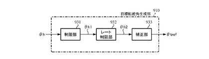
- FIG. 24 shows a configuration example of the target turning angle generation unit 910.
- the target turning angle generation unit 910 includes a limiting unit 931, a rate limiting unit 932, and a correcting unit 933.
- the limiter 931 limits the upper and lower limit values of the steering angle ⁇ h and outputs the steering angle ⁇ h1. Similar to the limiting unit 257 in the steering wheel return compensating unit 250 and the output limiting unit 350 in the torsion angle control unit 300, an upper limit value and a lower limit value for the steering angle ⁇ h are set in advance and are limited.
- the rate limiting unit 932 sets a limit value and limits the amount of change in the steering angle ⁇ h1 in order to avoid a sudden change in the steering angle, and outputs the steering angle ⁇ h2. For example, when the difference from the steering angle ⁇ h1 one sample before is set as the change amount, and the absolute value of the change amount is larger than a predetermined value (limit value), the steering angle is adjusted so that the absolute value of the change amount becomes the limit value. ⁇ h1 is added / subtracted and output as the steering angle ⁇ h2. When the steering angle ⁇ h1 is less than the limit value, the steering angle ⁇ h1 is output as the steering angle ⁇ h2. Note that instead of setting a limit value for the absolute value of the amount of change, it is also possible to set an upper limit value and a lower limit value for the amount of change to impose a limit. The rate may be limited.
- the correction unit 933 corrects the steering angle ⁇ h2 and outputs the target turning angle ⁇ tref. For example, like the basic map unit 210 in the target steering torque generation unit 200, using a map that defines the characteristics of the target turning angle ⁇ tref with respect to the magnitude
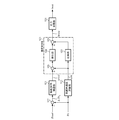
- FIG. 25 shows a configuration example of the steering angle control unit 920.
- the turning angle control unit 920 has the same configuration as the configuration example of the twist angle control unit 300 shown in FIG. 13 except for the stabilization compensating unit 340 and the adding unit 362, and has a target twist angle ⁇ ref and a twist.
- the target turning angle ⁇ tref and the turning angle ⁇ t are input instead of the angle ⁇ , and the turning angle feedback (FB) compensation unit 921, the turning angular velocity calculation unit 922, the speed control unit 923, the output limiting unit 926, and the subtraction unit 927.
- the torsion angle FB compensation unit 310, the torsion angular velocity calculation unit 320, the velocity control unit 330, the output limiting unit 350, and the subtraction unit 361 perform the same operation.
- the angle sensor 73 detects the steering angle ⁇ t
- the angle sensor 74 detects the motor angle ⁇ m (step S110)
- the steering angle ⁇ t is detected by the steering angle control unit 920
- the motor angle ⁇ m is measured by the angular velocity. It is input to each of the calculation units 951.
- the angular velocity calculation unit 951 differentiates the motor angle ⁇ m to calculate the motor angular velocity ⁇ m, and outputs the motor angular velocity ⁇ m to the right-turn / left-turn determination unit 500 (step S120).
- steps S10 to S60 shown in FIG. 14 After that, the same operation as steps S10 to S60 shown in FIG. 14 is performed, the reaction force motor 61 is driven, and the current control is performed (steps S130 to S170).
- the target turning angle generating unit 910 inputs the steering angle ⁇ h, and the steering angle ⁇ h is input to the limiting unit 931.
- the limiting unit 931 limits the upper and lower limit values of the steering angle ⁇ h by the preset upper limit value and lower limit value (step S180), and outputs the steering angle ⁇ h1 to the rate limiting unit 932.
- the rate limiting unit 932 limits the amount of change in the steering angle ⁇ h1 by a preset limit value (step S190), and outputs the steering angle ⁇ h2 to the correction unit 933.
- the correction unit 933 corrects the steering angle ⁇ h2 to obtain the target turning angle ⁇ tref (step S200), and outputs it to the turning angle control unit 920.
- the turning angle control unit 920 which has input the turning angle ⁇ t and the target turning angle ⁇ tref, calculates the deviation ⁇ t 0 by subtracting the turning angle ⁇ t from the target turning angle ⁇ tref in the subtracting unit 927 (step S210).
- Deviation Derutashitati 0 is input to the turning angle FB compensation unit 921, the turning angle FB compensation unit 921 compensates the deviation Derutashitati 0 by multiplying the compensation value to the deviation ⁇ t 0 (step S220), the target turning angular velocity ⁇ tref is output to the speed control unit 923.
- the steered angular velocity calculation unit 922 inputs the steered angle ⁇ t, calculates the steered angular velocity ⁇ tt by a differential calculation with respect to the steered angle ⁇ t (step S230), and outputs it to the speed control unit 923.
- the speed control unit 923 calculates the motor current command value Imcta by the IP control similarly to the speed control unit 330 (step S240) and outputs it to the output limiting unit 926.
- the output limiter 926 limits the upper and lower limits of the motor current command value Imcta by the preset upper and lower limits (step S250) and outputs the motor current command value Imct (step S260).
- the motor current command value Imct is input to the current control unit 930, and the current control unit 930 uses the motor current command value Imct and the current value Imd of the drive motor 71 detected by the motor current detector 940 to drive the motor. 71 is driven and a current control is implemented (step S270).
- the speed control unit 923 in the turning angle control unit 920 does not use the IP control, but the PI control, the P control, the PID control, and the PI-D, like the speed control unit 330 in the torsion angle control unit 300. Control, etc. are feasible and any control of P, I and D may be used, and the follow-up control by the steering angle control unit 920 and the twist angle control unit 300 is generally used. It may be performed with a control structure.
- the steered angle control unit 920 is used in a vehicle device as long as it has a control configuration in which the actual angle (here, the steered angle ⁇ t) follows the target angle (here, the target steered angle ⁇ tref).
- the control configuration is not limited, and for example, a control configuration used in an industrial positioning device, an industrial robot, or the like may be applied.
- one ECU 50 controls the reaction force device 60 and the drive device 70.
- the ECU for the reaction force device 60 and the ECU for the drive device 70 are respectively controlled. It may be provided.
- the ECUs exchange data with each other by communication.
- the SBW system shown in FIG. 22 does not have a mechanical connection between the reaction force device 60 and the drive device 70, but when an abnormality occurs in the system, the column shaft 2 and the steering mechanism are connected to a clutch or the like.
- the present invention can also be applied to an SBW system that includes a mechanical torque transmission mechanism that mechanically couples with each other. In such an SBW system, when the system is normal, the clutch is turned off to release the mechanical torque transmission, and when the system is abnormal, the clutch is turned on to enable the mechanical torque transmission.
- the torsion angle control unit 300 in the above-described first to fourth embodiments and the assist control unit 700 in the third embodiment directly calculate the motor current command value Imc and the assist current command value Iac, Before calculating them, the motor torque (target torque) desired to be output may be calculated first, and then the motor current command value and the assist current command value may be calculated. In this case, in order to obtain the motor current command value and the assist current command value from the motor torque, the generally used relationship between the motor current and the motor torque is used.
- a main object of the present invention is a means for realizing a target steering torque for performing steering wheel return compensation, and means for realizing the followability of the steering torque with respect to the target steering torque is limited to the above-mentioned converter and torsion angle controller. You don't have to.
Landscapes
- Engineering & Computer Science (AREA)
- Chemical & Material Sciences (AREA)
- Combustion & Propulsion (AREA)
- Transportation (AREA)
- Mechanical Engineering (AREA)
- Steering Control In Accordance With Driving Conditions (AREA)
- Power Steering Mechanism (AREA)
Abstract
Le problème selon la présente invention consiste à fournir un dispositif de direction de véhicule qui peut facilement atteindre un couple de direction équivalent à un angle de direction, ou similaire, indépendamment de l'état d'une surface de route et de changements des caractéristiques mécaniques d'un système de direction du fait du vieillissement, et à retourner un volant de direction au niveau d'une position proche de la position centrale une fois que les mains ont quitté le volant de direction. La solution selon l'invention porte sur un dispositif de direction de véhicule destiné à mettre en œuvre une commande d'assistance pour un système de direction comprenant une unité de génération de couple de direction cible destinée à générer un couple de direction cible, une unité de conversion destinée à convertir le couple de direction cible en un angle de torsion cible et une unité de commande d'angle de torsion destinée à calculer une valeur d'instruction de courant de moteur de sorte que l'angle de torsion suive l'angle de torsion cible, l'unité de génération de couple de direction cible étant équipée d'une unité de compensation de retour de volant de direction destinée à calculer, en fonction d'un couple de direction et de premières informations de vitesse angulaire, un premier signal de couple pour compenser le retour d'un volant de direction, délivre le premier signal de couple en tant que couple de direction cible et commande l'entraînement d'un moteur en fonction de la valeur d'instruction de courant de moteur.
Priority Applications (1)
| Application Number | Priority Date | Filing Date | Title |
|---|---|---|---|
| JP2020556648A JPWO2020100411A1 (ja) | 2018-11-15 | 2019-09-17 | 車両用操向装置 |
Applications Claiming Priority (2)
| Application Number | Priority Date | Filing Date | Title |
|---|---|---|---|
| JP2018-214621 | 2018-11-15 | ||
| JP2018214621 | 2018-11-15 |
Publications (1)
| Publication Number | Publication Date |
|---|---|
| WO2020100411A1 true WO2020100411A1 (fr) | 2020-05-22 |
Family
ID=70730686
Family Applications (1)
| Application Number | Title | Priority Date | Filing Date |
|---|---|---|---|
| PCT/JP2019/036298 Ceased WO2020100411A1 (fr) | 2018-11-15 | 2019-09-17 | Dispositif de direction de véhicule |
Country Status (2)
| Country | Link |
|---|---|
| JP (1) | JPWO2020100411A1 (fr) |
| WO (1) | WO2020100411A1 (fr) |
Cited By (6)
| Publication number | Priority date | Publication date | Assignee | Title |
|---|---|---|---|---|
| CN112623022A (zh) * | 2020-12-18 | 2021-04-09 | 浙江合众新能源汽车有限公司 | 一种驾驶员脱手状态下抑制方向盘摆动的方法 |
| CN113104106A (zh) * | 2021-05-27 | 2021-07-13 | 福建龙马环卫装备股份有限公司 | 用于自跟随清吸机的双模式线控转向控制系统及方法 |
| CN115158442A (zh) * | 2022-08-16 | 2022-10-11 | 中国第一汽车股份有限公司 | 助力力矩的确定方法、装置、存储介质及处理器 |
| JP2023127935A (ja) * | 2022-03-02 | 2023-09-14 | トヨタ自動車株式会社 | 制御装置、操舵装置、制御方法、プログラム |
| JPWO2023203751A1 (fr) * | 2022-04-22 | 2023-10-26 | ||
| GB2644037A (en) * | 2024-09-12 | 2026-03-18 | Jcb Access Ltd | Working vehicle steering system |
Families Citing this family (1)
| Publication number | Priority date | Publication date | Assignee | Title |
|---|---|---|---|---|
| CN114475776B (zh) * | 2022-03-21 | 2023-04-18 | 中国第一汽车股份有限公司 | 一种扭矩补偿方法、装置、车辆及存储介质 |
Citations (7)
| Publication number | Priority date | Publication date | Assignee | Title |
|---|---|---|---|---|
| JPH08175404A (ja) * | 1994-12-21 | 1996-07-09 | Mitsubishi Electric Corp | 電動パワーステアリング装置 |
| JP2003306161A (ja) * | 2002-04-12 | 2003-10-28 | Toyoda Mach Works Ltd | 電気式動力舵取装置 |
| JP2006137281A (ja) * | 2004-11-11 | 2006-06-01 | Showa Corp | 電動パワーステアリング装置 |
| JP2008273246A (ja) * | 2007-04-25 | 2008-11-13 | Honda Motor Co Ltd | 操舵システム |
| JP2011131629A (ja) * | 2009-12-22 | 2011-07-07 | Jtekt Corp | 電動パワーステアリング装置 |
| WO2014167631A1 (fr) * | 2013-04-08 | 2014-10-16 | 三菱電機株式会社 | Dispositif et procédé de commande de direction |
| WO2018147371A1 (fr) * | 2017-02-09 | 2018-08-16 | 日本精工株式会社 | Dispositif de direction assistée électrique |
-
2019
- 2019-09-17 WO PCT/JP2019/036298 patent/WO2020100411A1/fr not_active Ceased
- 2019-09-17 JP JP2020556648A patent/JPWO2020100411A1/ja active Pending
Patent Citations (7)
| Publication number | Priority date | Publication date | Assignee | Title |
|---|---|---|---|---|
| JPH08175404A (ja) * | 1994-12-21 | 1996-07-09 | Mitsubishi Electric Corp | 電動パワーステアリング装置 |
| JP2003306161A (ja) * | 2002-04-12 | 2003-10-28 | Toyoda Mach Works Ltd | 電気式動力舵取装置 |
| JP2006137281A (ja) * | 2004-11-11 | 2006-06-01 | Showa Corp | 電動パワーステアリング装置 |
| JP2008273246A (ja) * | 2007-04-25 | 2008-11-13 | Honda Motor Co Ltd | 操舵システム |
| JP2011131629A (ja) * | 2009-12-22 | 2011-07-07 | Jtekt Corp | 電動パワーステアリング装置 |
| WO2014167631A1 (fr) * | 2013-04-08 | 2014-10-16 | 三菱電機株式会社 | Dispositif et procédé de commande de direction |
| WO2018147371A1 (fr) * | 2017-02-09 | 2018-08-16 | 日本精工株式会社 | Dispositif de direction assistée électrique |
Cited By (11)
| Publication number | Priority date | Publication date | Assignee | Title |
|---|---|---|---|---|
| CN112623022A (zh) * | 2020-12-18 | 2021-04-09 | 浙江合众新能源汽车有限公司 | 一种驾驶员脱手状态下抑制方向盘摆动的方法 |
| CN113104106A (zh) * | 2021-05-27 | 2021-07-13 | 福建龙马环卫装备股份有限公司 | 用于自跟随清吸机的双模式线控转向控制系统及方法 |
| JP2023127935A (ja) * | 2022-03-02 | 2023-09-14 | トヨタ自動車株式会社 | 制御装置、操舵装置、制御方法、プログラム |
| JP7616125B2 (ja) | 2022-03-02 | 2025-01-17 | トヨタ自動車株式会社 | 制御装置、操舵装置、制御方法、プログラム |
| JPWO2023203751A1 (fr) * | 2022-04-22 | 2023-10-26 | ||
| WO2023203751A1 (fr) * | 2022-04-22 | 2023-10-26 | 三菱電機株式会社 | Dispositif de commande de direction et dispositif de direction à énergie électrique |
| JP7651067B2 (ja) | 2022-04-22 | 2025-03-25 | 三菱電機モビリティ株式会社 | 操舵制御装置及び電動パワーステアリング装置 |
| EP4512694A4 (fr) * | 2022-04-22 | 2025-08-20 | Mitsubishi Electric Corp | Dispositif de commande de direction et dispositif de direction à énergie électrique |
| CN115158442A (zh) * | 2022-08-16 | 2022-10-11 | 中国第一汽车股份有限公司 | 助力力矩的确定方法、装置、存储介质及处理器 |
| CN115158442B (zh) * | 2022-08-16 | 2024-05-17 | 中国第一汽车股份有限公司 | 助力力矩的确定方法、装置、存储介质及处理器 |
| GB2644037A (en) * | 2024-09-12 | 2026-03-18 | Jcb Access Ltd | Working vehicle steering system |
Also Published As
| Publication number | Publication date |
|---|---|
| JPWO2020100411A1 (ja) | 2021-09-24 |
Similar Documents
| Publication | Publication Date | Title |
|---|---|---|
| JP7153244B2 (ja) | 車両用操向装置 | |
| JP6504322B2 (ja) | 電動パワーステアリング装置 | |
| JP6628017B1 (ja) | 車両用操向装置 | |
| JP6531876B2 (ja) | 電動パワーステアリング装置 | |
| JP7170971B2 (ja) | 車両用操向システムの制御装置 | |
| JP7211438B2 (ja) | 車両用操向装置 | |
| WO2020100411A1 (fr) | Dispositif de direction de véhicule | |
| CN109572807B (zh) | 电动助力转向装置 | |
| JP6702513B2 (ja) | 車両用操向装置 | |
| JP7199643B2 (ja) | 車両用操向装置 | |
| WO2019167661A1 (fr) | Dispositif de direction de véhicule | |
| WO2020115973A1 (fr) | Dispositif de direction de véhicule | |
| WO2015122043A1 (fr) | Dispositif de direction à assistance électrique | |
| JP7223306B1 (ja) | 車両用操向システムの制御装置 | |
| JP7222309B2 (ja) | 車両用操向装置 | |
| WO2020183838A1 (fr) | Dispositif de direction de véhicule | |
| JP7153239B2 (ja) | 車両用操向装置 | |
| JP7437603B2 (ja) | 車両用操向装置 | |
| JP2021123288A (ja) | 車両用操向装置 |
Legal Events
| Date | Code | Title | Description |
|---|---|---|---|
| 121 | Ep: the epo has been informed by wipo that ep was designated in this application |
Ref document number: 19884246 Country of ref document: EP Kind code of ref document: A1 |
|
| ENP | Entry into the national phase |
Ref document number: 2020556648 Country of ref document: JP Kind code of ref document: A |
|
| NENP | Non-entry into the national phase |
Ref country code: DE |
|
| 122 | Ep: pct application non-entry in european phase |
Ref document number: 19884246 Country of ref document: EP Kind code of ref document: A1 |