WO2020100522A1 - マーク検出システム、信号処理回路、コンピュータプログラムおよび方法 - Google Patents
マーク検出システム、信号処理回路、コンピュータプログラムおよび方法 Download PDFInfo
- Publication number
- WO2020100522A1 WO2020100522A1 PCT/JP2019/041085 JP2019041085W WO2020100522A1 WO 2020100522 A1 WO2020100522 A1 WO 2020100522A1 JP 2019041085 W JP2019041085 W JP 2019041085W WO 2020100522 A1 WO2020100522 A1 WO 2020100522A1
- Authority
- WO
- WIPO (PCT)
- Prior art keywords
- image
- mark
- database
- imaging device
- acquired
- Prior art date
- Legal status (The legal status is an assumption and is not a legal conclusion. Google has not performed a legal analysis and makes no representation as to the accuracy of the status listed.)
- Ceased
Links
Images







Classifications
-
- B—PERFORMING OPERATIONS; TRANSPORTING
- B25—HAND TOOLS; PORTABLE POWER-DRIVEN TOOLS; MANIPULATORS
- B25J—MANIPULATORS; CHAMBERS PROVIDED WITH MANIPULATION DEVICES
- B25J13/00—Controls for manipulators
- B25J13/08—Controls for manipulators by means of sensing devices, e.g. viewing or touching devices
-
- G—PHYSICS
- G01—MEASURING; TESTING
- G01B—MEASURING LENGTH, THICKNESS OR SIMILAR LINEAR DIMENSIONS; MEASURING ANGLES; MEASURING AREAS; MEASURING IRREGULARITIES OF SURFACES OR CONTOURS
- G01B11/00—Measuring arrangements characterised by the use of optical techniques
-
- G—PHYSICS
- G06—COMPUTING OR CALCULATING; COUNTING
- G06T—IMAGE DATA PROCESSING OR GENERATION, IN GENERAL
- G06T7/00—Image analysis
-
- H—ELECTRICITY
- H10—SEMICONDUCTOR DEVICES; ELECTRIC SOLID-STATE DEVICES NOT OTHERWISE PROVIDED FOR
- H10P—GENERIC PROCESSES OR APPARATUS FOR THE MANUFACTURE OR TREATMENT OF DEVICES COVERED BY CLASS H10
- H10P72/00—Handling or holding of wafers, substrates or devices during manufacture or treatment thereof
Definitions
- the present disclosure relates to a mark detection system, a signal processing circuit, a computer program and a method.
- a mark detection system is known in which a work is photographed by a camera, and an alignment mark (hereinafter, simply referred to as “mark”) given to the work is detected by image processing.
- mark an alignment mark
- image processing By determining the position and / or orientation of the workpiece based on the position and orientation of the alignment mark, subsequent processing, such as gripping and unloading of the workpiece by the robot, is possible. ..
- Japanese Patent Laying-Open No. 2012-138548 discloses a technique of detecting a mark by moving the field of view in order from the periphery of the shooting reference position when the mark cannot be detected at the shooting reference position.
- a mark detection system is a mark detection system that detects a mark by using an image pickup device, and an image pickup device having a field of view capable of partially taking an image of an article to which the mark is attached.
- a plurality of images not including the image of the mark are associated with at least one image feature amount of each image, and positional relationship data indicating a relationship between the position represented by each image and the position of the mark.
- a memory device and a signal processing device are provided, and during the mark detection operation, the signal processing device causes the image capturing device to capture a part of the article, and the image acquired from the image capturing device includes the image of the mark. If not, by comparing the image feature amount of the acquired image and the image feature amount of each image stored in the storage device with reference to the database, if the comparison result is a match, The positional relationship data associated with the matched image is read from the database, and the position of the imaging device is changed using the read positional relationship data so that the mark is in the visual field of the imaging device. After generating and outputting a control signal for changing the position, the image of the mark is detected from the image taken again by using the image pickup device. ..
- a signal processing circuit is a signal processing circuit used in a mark detection system that detects an image using an imaging device in an exemplary embodiment, and the mark detection system partially detects an article to which a mark is added. And a storage device for storing a database acquired by a mark position learning operation, wherein the database captures different parts of the article in a plurality of times by the imaging device.
- a plurality of images obtained by the above for at least one image not including the image of the mark, at least one image feature amount of each image and a relationship between the position represented by each image and the position of the mark are shown.
- a storage device that associates positional relationship data with each other, wherein the signal processing circuit causes the image pickup device to photograph a part of the article at the time of mark detection operation, and an image obtained from the image pickup device.
- the database is referred to, the image feature amount of the acquired image is compared with the image feature amount of each image stored in the storage device, and the comparison result If the two match, the positional relationship data associated with the matched image is read from the database, and the read positional relationship data is used so that the mark is placed in the visual field of the imaging device.
- a control signal for changing the position of the image pickup device is generated and output, and after changing the position, the image of the mark is detected from an image captured again using the image pickup device. ..
- a computer program is a computer program for operating a signal processing circuit used in a mark detection system that detects a mark using an imaging device, and the mark detection system is a mark detection system.
- a storage device for storing a database acquired by a mark position learning operation, wherein the database captures different parts of the article.
- at least one image feature amount of each image and a position represented by each image and a plurality of images not including the image of the mark At least one image feature amount of each image and a position represented by each image and a plurality of images not including the image of the mark.
- a storage device that associates positional relationship data indicating a relationship with the position of the mark, and the computer program causes the signal processing circuit to control the imaging device to perform the mark detection operation.
- the image feature amount of the obtained image is stored in the storage device with reference to the database.
- the comparison result is matched, the positional relationship data related to the matched image is read out, and the read positional relationship data is used.
- a control signal for changing the position of the image pickup device is generated and output so that the mark is included in the visual field of the image pickup device, and after changing the position, the image is taken again by using the image pickup device.
- the image of the mark is detected from the formed image. ..
- the method of the present disclosure is, in an exemplary embodiment, a method performed using a mark detection system that detects a mark using an imaging device, the mark detection system comprising: And a storage device that stores a database acquired by a mark position learning operation, wherein the database captures different parts of the article by a plurality of times by the imaging device.
- a plurality of images obtained by performing the above-mentioned processing regarding a plurality of images not including the image of the mark, at least one image feature amount of each image and a relationship between the position represented by each image and the position of the mark are described.
- the positional relationship data shown is associated with a storage device and a signal processing device, and at the time of mark detection operation, the imaging device is caused to photograph a part of the article, and the signal processing circuit
- the signal processing circuit stores the database.
- the image feature amount of the acquired image and the image feature amount of each image stored in the storage device are compared, and when the comparison result is a match, the database is set to the matched image.
- the signal processing circuit is caused to detect the image of the mark from the image captured again by using the imaging device.
- a mark detection system a signal processing circuit, a computer program, and a method capable of searching for a mark in a short time are provided.
- FIG. 1 is a diagram schematically showing a mark detection system 1000 of the present disclosure.
- FIG. 2 is a diagram showing a connection relationship between the articulated robot 100, the controller 200, and the imaging device 300, and a hardware configuration example of the controller 200.
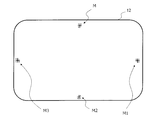
- FIG. 3 is a diagram showing an example of the shapes of the marks M and M1 to M3 according to the present disclosure.
- FIG. 4 is a diagram showing the top plate 12 divided into 30 regions.
- FIG. 5 is a diagram showing images GA3 and GA4 of areas A3 and A4 captured by the image capturing apparatus 300.
- FIG. 6 is a diagram showing an example of a plurality of partial images obtained by dividing the image GA3 for pattern matching.
- FIG. 7 is a diagram for explaining the relationship between the position represented by the image GA3 and the position of the mark M.
- FIG. 8 is a diagram showing a process of extracting the image feature amount from the partial image 3-1.
- FIG. 9 is a diagram showing an example of a database DB in which data indicating the amount of positional deviation and image feature amounts (edge image files) are associated with each other.
- FIG. 10 is a diagram showing a region P1 that the image capturing apparatus 300 first captured.
- FIG. 11 is a diagram showing a concept of a process of comparing the image feature amount of the partial region 3-3 with the image feature amount of each of the plurality of partial regions 252.
- FIG. 12 is a diagram showing an image GA3 of an area A3 used for learning and an image GP1 of an area P1 taken by the imaging device 300.
- FIG. 13 is a diagram showing a concept of a process of comparing the image feature amount of the partial regions 2-3 included in the image GA3 with the image feature amount of each of the plurality of partial regions 252 set in the image GP1. ..
- FIG. 14 is a diagram showing, by arrows, the correspondence relationship between each partial area of the image GA3 of the area A3 used for learning and the partial area of the image GP1 of the area P1 having the smallest sum of squared errors. is there.
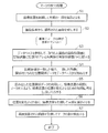
- FIG. 15 is a flowchart showing a procedure of processing executed by the CPU 210.
- FIG. 15 is a flowchart showing a procedure of processing executed by the CPU 210.
- FIG. 16 is a diagram showing an example in which the center C of the visual field of the image pickup apparatus 300 after movement does not match the center point O of the image GM of the mark.
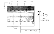
- FIG. 17 is a diagram showing new positional deviations ⁇ x ′ and ⁇ y ′ after updating the positional deviations ⁇ x and ⁇ y.
- FIG. 18 is a diagram showing an example of the updated image GA3 database DB.
- FIG. 19 is a diagram showing an example of the image GA3 database DB to which the priority is introduced.
- Unmanned guided vehicle means a trackless vehicle that manually or automatically loads luggage into the main body, automatically travels to the designated location, and manually or automatically unloads.
- Unmanned guided vehicles include unmanned towing vehicles and unmanned forklifts.
- the "unmanned guided vehicle” has a mounting table on which an article is mounted.
- the mounting table may include a wide range of objects such as a top plate and an arm on which an object can be mounted. ..
- An "object” is an object including a work or a work mounting table.
- the “work” is various things such as products or parts.
- the article when the article is a work, the article is placed on the top plate of the AGV and transported, and is loaded into a transporting vehicle by a human or a pick-up robot and is delivered. ..
- the “mark” is a mark that can be distinguished from others based on an image that can be acquired by an image pickup device such as a camera.
- the “mark” may include characters, figures, symbols or colors, or a combination thereof.
- a line drawing, a pattern, or a three-dimensional shape having a specific pattern is also included in the “mark”.
- the marks used for positioning are called “alignment marks”.
- the "mark” is an "alignment mark”.
- an example of using a “mark” for positioning will be described. In that case, the “mark” is synonymous with the “alignment mark”.
- the mark detection system is used to detect a predetermined mark using the image pickup device.
- the mark detection system according to the present embodiment performs processing capable of quickly moving the imaging device to the position of the mark when the mark does not exist within the visual field of the imaging device. ..
- FIG. 1 schematically shows a mark detection system 1000 of the present disclosure.
- the mark detection system 1000 of the present disclosure includes an articulated robot 100, a controller 200, and an imaging device 300 in a non-limiting exemplary embodiment.
- the mark detection system 1000 detects a mark given to a mounting table on which a work is placed, or a mark given to the work itself having a size that does not entirely fit in the field of view of the imaging device.
- An example of the mounting table is an AGV top plate, but other examples are a movable table and a fixed table. ..
- the AGV 10 places the work W on the top plate 12 and conveys the work W, and stops the work W at a predetermined position.
- the mark M is previously attached to the mounting table of the work W.
- the mark detection system 1000 detects the mark M using the imaging device 300.
- the mark detection system 1000 determines the position of the work, that is, the position and / or the direction of the work based on the position and the direction of the mark M. After the positioning, the mark detection system 1000 picks up the work W using the articulated robot 100 and sends it to the subsequent process.
- the specific content of the process of detecting the mark M using the imaging device 300 will be described in detail later. ..
- the articulated robot 100 and the controller 200 shown in FIG. 1 are fixed to the floor, but such an installation method is an example.
- the articulated robot 100 and the controller 200 may be miniaturized and installed on another AGV different from the AGV 10. ..
- the work may be carried by a cart manually pushed by an operator instead of being carried by the AGV 10.
- the position of the trolley does not always stop at the same position, but may be different each time.
- the mark detection system according to the present disclosure described later can be used to detect a mark in a short time, determine the position and / or orientation of the work, and pick up the work. ..
- the articulated robot 100 is generally also called a robot arm or a manipulator.
- the articulated robot 100 has joints 110A to 110C, arms 120A and 120B, and an end effector 130.
- Each of the joints 110A to 110C has a motor, and rotates the arms 120A and / or 120B around the rotation axis.
- the end effector 130 is a device attached to the arm 120B and used so that the articulated robot 100 can work.
- the exemplary end effector 130 shown in FIG. 1 has a two-finger gripper 140.
- the two-finger gripper 140 can adjust the distance between two fingers to sandwich and hold the work W. ..
- An example of the controller 200 is a computer.
- the controller 200 causes the imaging device 300 to perform image capturing, acquires an image signal obtained by the image capturing, and performs a process of detecting a mark.
- the controller 200 performs a predetermined positioning process to determine the position and / or orientation of the work W.
- the controller 200 controls the articulated robot 100 and the two-finger gripper 140 based on the determined position and / or orientation to pick up the work W.
- the controller 200 controls the articulated robot 100 and the two-finger gripper 140 based on the determined position and / or orientation to pick up the work W.
- the control of the articulated robot 100 and the process of detecting the mark may be performed by separate computers. ..
- the imaging device 300 is a device that outputs an image signal of a captured subject image.
- the image signal is sent to the controller 200 by wire.
- a typical example of the imaging device 300 is an imaging device including an area sensor such as a CMOS image sensor or a CCD image sensor in which a large number of photodiodes are arranged in a matrix.
- the image pickup apparatus 300 generates data of a color image or a monochrome image of a subject.
- various cameras for visual inspection can be used. ..
- the image pickup apparatus 300 has a field of view that is relatively narrower than that of the work W and is capable of partially photographing the work W.
- the “field of view” referred to here is, for example, that the articulated robot 100 has a predetermined posture, and the imaging device 300 faces the subject and acquires a feature such as the shape of the mark M to photograph the mark M.
- the field of view when located at a possible distance. ..
- the reason why the field of view of the imaging device 300 is narrow is as follows.
- the imaging device 300 used for detecting the mark and determining the position and / or orientation of the work is assumed to be used for highly accurate work in other processes, and a high-magnification lens is adopted. ing. Therefore, the field of view becomes inevitably narrow.
- variable magnification lens is complicated and leads to an increase in cost. Furthermore, since the weight of the device or the lens increases, the mounting may not be allowed in the first place due to the weight limit that can be mounted on the end effector. ..
- FIG. 2 shows a connection relationship between the articulated robot 100, the controller 200, and the imaging device 300, and a hardware configuration example of the controller 200.
- the controller 200 has a CPU 210 that is a signal processing device and a memory 220 that is a storage device. ..
- the controller 200 is connected to the articulated robot 100 and the imaging device 300 by wires via one or more communication terminals (not shown).
- the controller 200 and the articulated robot 100 transmit and receive signals via the communication terminal.
- the controller 200 and the image pickup apparatus 300 transmit and receive a shooting instruction signal and an image signal acquired by shooting via the communication terminal.
- the communication may be performed wirelessly. ..
- the signal transmitted from the controller 200 to the articulated robot 100 may include designation of one or a plurality of joints of the articulated robot 100, designation of a rotation angle for each designated joint, designation of a rotation speed, and the like.
- the signal transmitted from the articulated robot 100 to the controller 200 may include confirmation of reception of the transmitted signal and notification of completion of operation. ..
- a computer program is stored in the memory 220.
- the computer program is a set of instructions executed by the CPU 210.
- the CPU 210 executes the photographing process using the imaging device 300 and the mark M detection process using the acquired image.
- the CPU 210 executes a predetermined positioning process using the detected mark M. Based on the result of the positioning process, the CPU 210 can rotate each motor of each joint of the articulated robot 100 and pick up the work W. ..
- the operation of the mark detection system 1000 is controlled by the CPU 210 of the controller 200, but the description becomes complicated if the CPU 210 appears in all the explanations. Therefore, in the following, it may be simply described as "the imaging device 300 photographs a predetermined area.”
- the operation executed by this expression is that the CPU 210 actually controls each joint of the multi-joint robot 100 to control so that the visual field of the imaging device 300 falls within a predetermined area.
- the memory 220 stores a database DB that associates various data after learning described later.
- the database DB At least one image feature amount of each image and a position indicating the relationship between the position represented by each image and the position of the mark are prepared for a plurality of images not including the image of the mark prepared for learning.
- the relational data are related. More specific contents of the database DB will be described later. ..
- FIG. 3 illustrates an example of the shapes of the marks M and M1 to M3 according to the present disclosure.
- four marks are provided near the center of each side of the top plate 12 of the AGV 10.
- Each mark has a different pattern, and the detected position can be determined by the position and orientation of the detected pattern.
- a relatively large mark is shown in FIG. 3, this is for convenience of description.
- the mark may be smaller.
- the number, position, shape (pattern), etc. of the marks are arbitrary. Those skilled in the art can appropriately increase or decrease the number and change the position and the pattern within the required range. ..
- the memory 220 which is a storage device, holds the above-described data such as the number, position, and shape of the marks. By using these data, the CPU 210 can identify the image of the mark from the image acquired from the imaging device 300. In this specification, such data used for identifying the image of the mark from the captured image is referred to as “feature data” regarding the image of the mark.
- the CPU 210 refers to the characteristic data and determines whether or not the captured image includes the image of the mark. Specifically, the CPU 210 refers to the characteristic data in the memory 220, and determines whether or not there is an image object having a characteristic that matches the characteristic data in the captured image.
- the CPU 210 determines that the image includes a mark image. If no such image object exists, the CPU 210 determines that the image does not include the mark image. If the characteristic data is prepared in advance, the CPU 210 can detect any mark. ..
- the mark detection operation performed by the mark detection system 1000 includes a mark position learning operation and a mark detection operation.
- the mark position learning operation is performed prior to the first mark detection operation. ..
- the mark position learning operation is a learning operation performed by the mark detection system 1000 using a plurality of images photographed for learning.
- the target of learning is the relationship between the image feature amount of an image that does not include a mark and the positional shift amount from the position represented by each image to the center position of the mark (hereinafter referred to as “shift amount”).
- the imaging device 300 captures at least a part of the top plate 12 of the AGV 10 in a field of view in a plurality of times.
- at least one image feature amount of each image for example, an image feature amount regarding an edge in the image and an image of the mark are included.
- the relationship with the amount of deviation from the position represented by each missing image (for example, the center position of the visual field at the time of shooting each image) to the center position of the mark is learned.
- the positional relationship data indicating the image feature amount and the shift amount of the image not including the mark, which is the learning result, are associated and stored as a database DB, and are used in the next mark detection operation. ..
- the mark detection operation is an operation of detecting a mark, which is performed by the CPU 210 of the mark detection system 1000 using the image captured by the image capturing apparatus 300 and acquired from the image capturing apparatus 300.
- the CPU 210 of the mark detection system 1000 refers to the database, and the image feature amount of the acquired image and the learned image feature amount stored in the database DB. Compare with.
- the comparison result matches the predetermined condition
- the CPU 210 determines that the two image feature amounts match.
- An example of the predetermined condition is whether or not the size of the degree of coincidence between the two is less than a predetermined threshold value.
- the image feature amount For example, consider the case where the position and range of an edge in an image are used as the image feature amount.
- the difference between the image feature amount of the acquired image and the image feature amount stored in the database DB is calculated, and the sum of squares of the difference is calculated. If the magnitude of the sum of squares is less than the threshold, it can be said that the difference between the two image feature amounts is small. That is, it can be said that the acquired image includes the same area as the image used for learning or an overlapping area.
- the image feature amount may be obtained from the entire acquired image or may be obtained from a partial image that is a part of the acquired image.
- the CPU 210 further refers to the database DB and reads the positional relationship data indicating the shift amount to the center position of the mark, which is associated with the image used for learning.
- the CPU 210 uses the read positional relationship data to generate and output a control signal for changing the position of the imaging device 300 so that a mark is placed in the field of view of the imaging device 300.
- the CPU 210 detects the image of the mark from the image captured again using the imaging device 300. Thereby, even when the acquired image does not include the image of the mark, the CPU 210 can move the imaging device 300 to the position of the mark and detect the mark. Since it is not necessary to adopt a method (a brute force detection method) of photographing all areas while changing the photographing range to detect the marks, it is possible to quickly detect the positions of the marks. ..
- the mark position learning operation and the mark detection operation will be described below. ..
- FIG. 4 shows the top plate 12 divided into 30 areas. For convenience of explanation, it is assumed that each area is equal to the size of the field of view of the imaging device 300.
- the numbers A1, A2, ..., A6 are sequentially assigned from the upper left area to the right, and the numbers B1, B2, ... Are assigned to the right in the next row.
- numbers are given up to the last area E6 in the fifth row (E column). ..
- the image capturing apparatus 300 captures each area by a brute force detection method. Pay attention to the top row A. A mark M is given to the area A4. As a result of shooting by the image pickup apparatus 300, the image of the area A4 includes the mark image, and the images of the areas A1 to A3, A5, and A6 do not include the mark image. It should be noted that the image of the region of row A may include not only the image of the top plate 12 but also an image of the floor or the like below the top plate 12. Hereinafter, description will be made focusing on the areas A3 and A4. .
- FIG. 5 shows images GA3 and GA4 of the areas A3 and A4 captured by the image capturing apparatus 300.
- the images GA3 and GA4 are arranged adjacent to each other.
- the image GA4 includes a mark image GM which is an image of the mark M.
- the image GA3 does not include the mark image GM, but the adjacent image GA4 has the mark image GM during learning. Therefore, in the present embodiment, positional relationship data indicating the relationship between the position represented by the image GA3 and the position of the mark M is acquired. ..
- the relationship between the position represented by the image GA3 and the position of the mark M is uniquely determined based on a given point (eg, center point) in the image GA3. ..
- FIG. 6 shows an example of a plurality of partial images obtained by dividing the image GA3 for pattern matching described later.
- the image GA3 is divided into 16 partial images each having the same shape and area. ..
- FIG. 7 is a diagram for explaining the relationship between the position represented by the image GA3 and the position of the mark M.
- the positions of the image GA3 and the image GM of the mark will be used for description.
- the position of the center point C of the image GA3 corresponds to the position of the center of the visual field of the imaging device 300.
- the CPU 210 of the controller 200 preliminarily determines a shift amount ( ⁇ x, ⁇ y) indicating how much the imaging device 300 should be moved from the position where the image GA3 is acquired so that the center of the mark M matches the center of the visual field. It is acquired and stored in the memory 220. ..
- FIG. 7 shows the deviation amounts ⁇ x and ⁇ y for each coordinate axis from the center point C of the visual field to the center point O of the mark M when the image GA3 is captured.
- the sign "+" on the X axis indicates the right direction in the drawing, and the sign "-" on the Y axis indicates the upper part of the drawing. This value may be measured and input by the operator of the mark detection system 1000, or may be calculated by the CPU 210.
- the same shift amount ( ⁇ x and ⁇ y) is associated with all the partial images 1-1, 1-2, etc. that form the image GA3. ..
- FIG. 8 shows a process of extracting the image feature amount from the partial image 3-1.
- the CPU 210 of the controller 200 performs a process of extracting an edge included in the partial image 3-1 and employs the data of the extracted edge image 3-1-E as the image feature amount of the partial image 3-1.
- the CPU 210 associates the image feature amount with the data indicating the relationship (deviation amount) between the position represented by the image and the position of the mark, and stores the data in the memory 220 as a database DB.
- the edge in the partial image is adopted as the image feature amount, but this is only an example. Arbitrary features unique to each partial image can be adopted as the image feature amount. ..
- FIG. 9 shows an example of a database DB in which the data indicating the amount of deviation and the image feature amount (edge image file) are associated with each other.
- the CPU 210 creates a database DB for all the images (excluding the image including the mark image GM) of the region shown in FIG. 4, and stores the database DB in the memory 220. It should be noted that it is optional whether the database DB for each image is provided as a separate file or the database DB for each image is collectively included in one file. ..
- the mark position learning operation is completed by creating the database DB of each image by the above procedure. ..
- the mark detection operation is executed after the AGV 10 conveys the work W and stops at a predetermined position in front of the mark detection system 1000 as shown in FIG.
- the imaging device 300 photographs the top plate 12 on which the work W is placed. ..
- the image pickup apparatus 300 first takes an image of the region P1.
- the region P1 first captured by the imaging device 300 in the visual field does not always include the center position of the top plate 12. ..
- the CPU 210 of the controller 200 refers to the database DB to determine which of the learned regions the image feature amount included in the region P1 is included in. Specifically, the CPU 210 repeats the following processing, for example, in order from the area A1 (FIG. 4) to the last area E6 (FIG. 4). ..
- the CPU 210 compares the image feature amount of each partial region included in the region A1 (FIG. 4) with the image feature amount of each of the plurality of partial regions set in the region P1.
- FIG. 11 shows the image feature amount of the partial region 3-3 included in the image GA1 of the region A1 used for learning, and the image feature amount of each of the plurality of partial regions 252 set in the image GP1 of the region P1. It shows the concept of the process of comparing.
- the plurality of partial regions 252 can be set, for example, by shifting by several pixels and overlapping with other partial regions.
- the size of the partial area 3-3 and the size of each of the plurality of partial areas 252 are the same. This operation can be executed by using known template matching. ..
- the CPU 210 obtains the sum of the square error of the image feature amount of the partial area 3-3 and the image feature amount of each of the plurality of partial regions 252.
- the magnitude of the sum of the obtained squared errors is a parameter for evaluating how close the image in each partial region 252 is to the image in each partial region 3-3. The smaller the sum of squared errors, the more similar the images in the two partial regions are. ..
- the partial areas in the image GA1 do not match much in the image GP1.
- the CPU 210 determines that the number of sets of partial areas in which the magnitude of the sum of squared errors is equal to or smaller than the predetermined value T1 between the two images does not exist equal to or larger than the predetermined value T2. In such a case, the present specification may express that the comparison results of the two images do not match. On the contrary, if the number of sets of partial regions in which the magnitude of the sum of squared errors is equal to or smaller than a predetermined value T1 between two images is equal to or larger than the predetermined value T2, two It may be expressed that the image comparison results match. ..
- the CPU 210 calculates the magnitude of the sum of squared errors between the partial areas of the images of the areas A2 to E6 used for learning and the partial areas of the captured image GP1.
- processing regarding the image of the area A3 (FIG. 4) used for learning and the image GP1 will be illustrated. ..
- FIG. 12 shows an image GA3 of the area A3 used for learning and an image GP1 of the area P1 captured by the image capturing apparatus 300. Since the environments in which the images were taken are different, the images obtained are also different.
- FIG. 13 shows the concept of the process of comparing the image feature amount of the partial regions 2-3 included in the image GA3 with the image feature amount of each of the plurality of partial regions 252 set in the image GP1. Similar to the above example, the CPU 210 calculates the sum of squared errors between the image feature amounts for each partial area set in the image GP1. ..
- FIG. 14 shows by arrows the correspondence between the partial areas of the image GA3 of the area A3 used for learning and the partial areas of the image GP1 of the area P1 having the smallest sum of squared errors. ..
- the CPU 210 determines the area. It is determined that the image GA3 of A3 and the image GP1 of the region P1 match. Since the threshold values T1 and T2 can largely change depending on the sizes of the images GA3 and GP1, the number of partial areas to be set, and the like, a specific example will be omitted. Those skilled in the art can appropriately set the conditions. ..
- the CPU 210 refers to the database DB and acquires the positional deviations ⁇ x and ⁇ y. Then, the CPU 210 moves the image pickup apparatus 300 by the positional shifts ⁇ x and ⁇ y. As a result, the image pickup apparatus 300 can be moved to the position of the mark quickly and reliably even from an image obtained by shooting a region not including the mark. ..
- FIG. 15 is a flowchart showing a procedure of processing executed by the CPU 210. ..
- step S1 the CPU 210 controls the imaging device 300 to cause the imaging device 300 to photograph a part of the top plate 12 (mounting table). For example, the CPU 210 transmits a shooting instruction signal (control signal) to the imaging device 300. The imaging device 300 captures a part of the top plate 12 according to the control signal and transmits the image signal of the acquired image to the controller 200. ..
- step S2 the CPU 210 receives an image signal from the imaging device 300 and acquires a captured image. ..
- step S3 is carried out. ..
- step S3 the CPU 210 refers to the database DB and compares the image feature amount of the acquired image with the image feature amount of each image stored in the memory 220.
- step S4 is processing when the comparison results match. ..
- step S4 the CPU 210 reads out the positional relationship data associated with the matched image from the database DB. ..
- step S5 the CPU 210 uses the read data to generate and output a control signal for changing the position of the imaging device 300 so that a mark is placed in the visual field of the imaging device 300.
- step S6 the CPU 210 changes the position of the imaging device 300 according to the output control signal, and then controls the imaging device 300 to cause the imaging device 300 to photograph a part of the top plate 12. ..
- step S7 the CPU 210 receives the image captured again from the imaging device 300 and detects the image of the mark from the image. ..
- the relationship between the position of each image other than the image including the image of the mark M and the center position of the mark M is learned by the mark position learning operation.
- the shift amount to the center position of the mark M associated with the image is included in the learned image.
- the first modified example is updating (re-learning) of the deviation amount. ..
- the imaging device 300 is moved using the positional deviations ⁇ x and ⁇ y acquired from the database DB.
- the positional deviations ⁇ x and ⁇ y are determined as positions where the mark M is detected at a predetermined position in the acquired image, for example, the center of the visual field, when the image capturing apparatus 300 is moved and then imaged again. Therefore, for example, the mark M should be detected at the center of the visual field of the imaging device 300. However, actually, the mark M is rarely detected at the center of the visual field. The reason is that the range of the image re-acquired by the imaging device 300 rarely matches the range of each image in the learning data used during learning. Therefore, normally, the center of the visual field of the image pickup apparatus 300 after movement does not coincide with the center point O of the mark M. ..
- FIG. 16 illustrates an example in which the center C of the visual field of the image pickup apparatus 300 after movement does not match the center point O of the image GM of the mark.
- the difference between the two is shown by two differences ( ⁇ x) and ( ⁇ y), respectively.
- the reference sign means that the position of the center point O when viewed from the center C of the visual field exists in the negative direction of the illustrated X axis and Y axis. ..
- the CPU 210 of the controller 200 acquires the differences ( ⁇ x) and ( ⁇ y) in order to cancel the displacement between the two, and uses the acquired differences ( ⁇ x) and ( ⁇ y) to detect the initial positional deviation ⁇ x and Update ⁇ y. That is, the CPU 210 uses the acquired differences ( ⁇ x) and ( ⁇ y) to update the positional deviations ⁇ x and ⁇ y that are the positional relationship data indicating the relationship between the position represented by each image in the database DB and the position of the mark M. To do. ..
- FIG. 17 shows new positional deviations ⁇ x ′ and ⁇ y ′ after updating the positional deviations ⁇ x and ⁇ y using the differences ( ⁇ x) and ( ⁇ y).
- ⁇ x ′ ⁇ x + ( ⁇ ⁇ x)
- ⁇ y ′ ⁇ y + ( ⁇ ⁇ y).
- FIG. 18 shows an example of the updated image GA3 database DB. Comparing with the pre-update database GA3 database DB shown in FIG. 9, it is understood that each value of the shift amount is updated. The description of the image feature amount column is omitted. ..
- the shift amount obtained by the mark position learning operation is updated according to the result of the mark detection operation. Since the database DB can be updated in accordance with the actual operating environment, the mark detecting operation can be executed quickly thereafter. ..
- the CPU 210 changes the position of the imaging device 300 according to the positional relationship data related to the images in the database DB with which the comparison results match, and then the image of the mark M from the image captured again using the imaging device 300. Is determined whether or not can be detected. Then, when the image of the mark M cannot be detected, the CPU 210 acquires an image while changing the position of the imaging device 300 in a predetermined order, and whether the image of the mark M exists in the acquired image. Determine whether or not.
- the CPU 210 may perform an operation of detecting the mark M from that position by a brute force detection method. More specifically, the CPU 210 acquires an image in a predetermined order while changing the position of the imaging device 300, and performs an operation of determining whether or not the image of the mark M is present in the acquired image. Then, the operation of detecting the mark M may be performed. Normally, it is considered that the mark M exists at a position relatively close to the mark M, although the mark M does not enter the visual field. Therefore, even if the brute force detection method is adopted, the CPU 210 can detect the mark M sufficiently quickly. Then, when the mark M can be detected, the data to which an incorrect shift amount is given may be updated. The updated data is generated by adding the initial displacement amount and the direction and distance moved by the detection operation by brute force. The CPU 210 may update the initial displacement amount stored in the database DB with the newly generated displacement amount. ..
- the database DB may be maintained without being updated. ..
- the second modification is the introduction of priority data indicating the priority of each image.
- the priority data is an additional parameter stored in the database DB in association with the image feature amount of each image for a plurality of images not including the image of the mark M.
- the priority indicates a degree to which the image feature amount used when comparing two images is useful in determining whether the two images match. In other words, the priority indicates the degree of ease of matching the comparison results when the image feature amounts are compared using the image feature amounts associated with each other on the database DB.
- the priority and its database DB will be described below by taking the image GA3 shown in FIG. 9 as an example. ..
- FIG. 19 shows an example of the image GA3 database DB to which the priority is introduced.
- the database DB in addition to the image feature amount for each partial image, the shift amount (positional relation data) indicating the relationship between the position represented by each image and the position of the mark, the priority indicating the “priority” of each partial image.
- the data is related. ..
- the significance of the priority will be described with reference to FIG. 7.
- the partial images 1-1 to 1-4 are dark in color as a whole, and the number of edges, which are the image feature amounts of this embodiment, is small at first glance. Therefore, it can be considered that the image feature amount of these partial images is not useful in determining whether or not the image feature amount of another image acquired from the image capturing apparatus 300 during the mark detection operation matches.
- the partial image 3-1 has a plurality of characteristic edges in terms of shape and position, it is useful for determining whether or not the partial image matches the image feature amount of the other image. Conceivable.
- the priority is a parameter that reflects such a situation. ..
- the shift amount of which partial image is used to control the image capturing apparatus 300. It is especially useful in deciding whether to move.
- the CPU 210 compares the image feature amount of the acquired partial area of the image with the image feature amount of the partial area of each image stored in the memory 220. When the CPU 210 determines that the comparison results match for the plurality of images stored in the memory 220, the CPU 210 selects a specific one image according to the priority level of each of the plurality of images. Read the related positional relationship data. More specifically, the positional relationship data associated with one specific image having the highest priority is read.
- the CPU 210 uses the read shift amount to move the imaging device 300. As a result, the imaging device 300 can be moved to the position where the mark is present more reliably.
- the image feature amount of the partial area of the acquired image is illustrated, but the image feature amount may be obtained from the entire acquired image. ..
- the priority may be fixed or updated. An example of updating will be described below. ..
- the CPU 210 determines that the image feature amount that matches the image feature amount of the partial image 3-1 exists in another image
- the CPU 210 moves the imaging device 300 according to the shift amount associated with the partial image 3-1 and moves the position. Change.
- the CPU 210 that has acquired a new image from the imaging device 300 determines whether the image GM of the mark actually exists in the image.
- the CPU 210 updates the priority associated with the partial image 3-1 to be higher. For example, in the example of FIG. 19, the priority may be increased by 1. Since the priority can be updated by following the actual operating environment, the CPU 210 can quickly execute the mark detection operation. ..
- the initial value of the priority may be appropriately set by the user of the mark detection system 1000, or may be given a uniform value at the beginning, for example, priority 1. ..
- the priority has been described in units of partial images, but the priority may be set in units of one image.
- the priority when it can be said that there is no image feature amount useful for identification inside the top plate 12 that does not include the edge, it is considered sufficient to set the priority for the entire image. ..
- the displacement amount of the positional displacement described so far is expressed as a difference in the X-axis direction and the Y-axis direction as shown in FIG. 7, but the expression method is an example.
- a polar coordinate system using an angle and a distance may be adopted. ..
- the imaging device 300 is attached to the end effector 130 in the present embodiment, but the configuration is an example.
- the imaging device 300 may be provided at another position.
- the imaging device 300 may be mounted on another AGV (second transport vehicle) different from the AGV 10 (first transport vehicle).
- the imaging device on the second transport vehicle captures the top plate of the first transport vehicle and marks it. Can be detected.
- the second transport vehicle may include an articulated robot in addition to the imaging device. That is, the second transport vehicle may include the articulated robot 100 having the imaging device 300 as shown in FIG.
- the CPU 210 of the controller 200 can detect the image of the mark and operate the articulated robot according to the detection result. As a result, the controller 200 can operate the articulated robot 100 at any position according to the detection result of the mark image to pick up and move the work W.
- the processing performed by the mark detection system 1000 is realized by the CPU 210 executing the computer program stored in the memory 220.
- a computer program is a set of instructions for causing the CPU 210 to execute the procedure (method) of the processing shown in FIG. 15, and is recorded on a recording medium such as a CD-ROM and distributed to the market as a product, or It can be transmitted through a telecommunication line such as the Internet.
- the CPU 210 and the memory 220 storing the computer program may be realized as a signal processing circuit such as a DSP (Digital Signal Processor) in which the computer program is incorporated in one semiconductor circuit. That is, such a DSP can function as the controller 200 of FIG.
- DSP Digital Signal Processor
- the mark detection system is used in a factory, a warehouse, a construction site, a physical distribution site, a hospital, etc. to detect a mark by using a captured image and perform positioning to move and convey a work such as luggage or a part. Can be suitably used.
Landscapes
- Engineering & Computer Science (AREA)
- Physics & Mathematics (AREA)
- General Physics & Mathematics (AREA)
- Computer Vision & Pattern Recognition (AREA)
- Theoretical Computer Science (AREA)
- Human Computer Interaction (AREA)
- Robotics (AREA)
- Mechanical Engineering (AREA)
- Image Analysis (AREA)
- Length Measuring Devices By Optical Means (AREA)
- Manipulator (AREA)
- Container, Conveyance, Adherence, Positioning, Of Wafer (AREA)
Abstract
【課題】マークの探索を高速化する。【解決手段】マーク検出システム(1000)の撮像装置(300)はマークMが付与された物品を部分的に撮影可能な視野を有する。記憶装置(220)は、マーク位置学習動作によって取得されたデータベース(DB)を記憶する。データベースは、物品の異なる部分を撮像装置によって複数回に分けて撮影して得られた複数の画像のうちの、マークの像を含まない各画像の少なくとも1つの画像特徴量、および、各画像が表す位置とマークの位置との関係を示す位置関係データ、を関係付けている。画像にマークの像が含まれていないとき、信号処理装置は、取得した画像の画像特徴量と記憶装置内の各画像の画像特徴量との比較し、比較結果が一致した場合、データベース内の、一致した画像に関係付けられた位置関係データを利用して撮像装置の位置を変化させ、その後再度撮影された画像からマークの像を検出する。
Description
本開示は、マーク検出システム、信号処理回路、コンピュータプログラムおよび方法に関する。
カメラでワークを撮影し、ワークに付与されたアラインメントマーク(以下、単に「マーク」と記述する。)を画像処理によって検出するマーク検出システムが知られている。アライメントマークの位置および向きに基づいて、ワークの位置および/または向きを決定することにより、その後の処理、例えばロボットによるワークの把持および搬出、が可能になる。
特開2012-138548号公報は、撮影基準位置でマークを検出できなかった場合、撮影基準位置の周辺から順に視野を移動させてマークを検出する技術を開示している。
ところで、上述した従来の技術は、マークの探索に時間を要していた。
本開示のマーク検出システムは、例示的な実施形態において、撮像装置を用いてマークを検出するマーク検出システムであって、マークが付与された物品を部分的に撮影可能な視野を有する撮像装置と、マーク位置学習動作によって取得されたデータベースを記憶する記憶装置であって、前記データベースは、前記物品の異なる部分を前記撮像装置によって複数回に分けて撮影して得られた複数の画像のうちの、前記マークの像を含まない複数の画像について、各画像の少なくとも1つの画像特徴量、および、各画像が表す位置と前記マークの位置との関係を示す位置関係データ、を関係付けている、記憶装置と、信号処理装置とを備え、マーク検出動作時において、前記信号処理装置は、前記撮像装置で前記物品の一部を撮影させ、前記撮像装置から取得した画像に前記マークの像が含まれていないとき、前記データベースを参照して、取得した前記画像の画像特徴量と前記記憶装置に記憶されている前記各画像の画像特徴量とを比較し、比較結果が一致した場合には、前記データベースから、一致した画像に関係付けられた前記位置関係データを読み出し、読み出した前記位置関係データを利用して、前記撮像装置の視野に前記マークが入るよう、前記撮像装置の位置を変化させるための制御信号を生成して出力し、前記位置を変化させた後に、前記撮像装置を用いて再度撮影された画像から前記マークの像を検出する。
本開示の信号処理回路は、例示的な実施形態において、撮像装置を用いて検出するマーク検出システムに用いられる信号処理回路であって、前記マーク検出システムは、マークが付与された物品を部分的に撮影可能な視野を有する撮像装置と、マーク位置学習動作によって取得されたデータベースを記憶する記憶装置であって、前記データベースは、前記物品の異なる部分を前記撮像装置によって複数回に分けて撮影して得られた複数の画像のうちの、前記マークの像を含まない複数の画像について、各画像の少なくとも1つの画像特徴量、および、各画像が表す位置と前記マークの位置との関係を示す位置関係データ、を関係付けている、記憶装置とを備えており、前記信号処理回路は、マーク検出動作時において、前記撮像装置に前記物品の一部を撮影させ、前記撮像装置から取得した画像に前記マークの像が含まれていないとき、前記データベースを参照して、取得した前記画像の画像特徴量と前記記憶装置に記憶されている前記各画像の画像特徴量とを比較し、比較結果が一致した場合には、前記データベースから、一致した画像に関係付けられた前記位置関係データを読み出し、読み出した前記位置関係データを利用して、前記撮像装置の視野に前記マークが入るよう、前記撮像装置の位置を変化させるための制御信号を生成して出力し、前記位置を変化させた後に、前記撮像装置を用いて再度撮影された画像から前記マークの像を検出する。
本開示のコンピュータプログラムは、例示的な実施形態において、撮像装置を用いてマークを検出するマーク検出システムに用いられる信号処理回路を動作させるためのコンピュータプログラムであって、前記マーク検出システムは、マークが付与された物品を部分的に撮影可能な視野を有する撮像装置と、マーク位置学習動作によって取得されたデータベースを記憶する記憶装置であって、前記データベースは、前記物品の異なる部分を前記撮像装置によって複数回に分けて撮影して得られた複数の画像のうちの、前記マークの像を含まない複数の画像について、各画像の少なくとも1つの画像特徴量、および、各画像が表す位置と前記マークの位置との関係を示す位置関係データ、を関係付けている、記憶装置とを備えており、マーク検出動作時において、前記コンピュータプログラムは前記信号処理回路に、前記撮像装置を制御して前記物品の一部を撮影させ、前記撮像装置から取得した画像に前記マークの像が含まれていないとき、前記データベースを参照して、取得した前記画像の画像特徴量と前記記憶装置に記憶されている前記各画像の画像特徴量とを比較させ、比較結果が一致した場合には、前記データベースから、一致した画像に関係付けられた前記位置関係データを読み出しさせ、読み出した前記位置関係データを利用して、前記撮像装置の視野に前記マークが入るよう、前記撮像装置の位置を変化させるための制御信号を生成して出力させ、前記位置を変化させた後に、前記撮像装置を用いて再度撮影された画像から前記マークの像を検出させる。
本開示の方法は、例示的な実施形態において、撮像装置を用いてマークを検出するマーク検出システムを用いて実行される方法であって、前記マーク検出システムは、マークが付与された物品を部分的に撮影可能な視野を有する撮像装置と、マーク位置学習動作によって取得されたデータベースを記憶する記憶装置であって、前記データベースは、前記物品の異なる部分を前記撮像装置によって複数回に分けて撮影して得られた複数の画像のうちの、前記マークの像を含まない複数の画像について、各画像の少なくとも1つの画像特徴量、および、各画像が表す位置と前記マークの位置との関係を示す位置関係データ、を関係付けている、記憶装置と、信号処理装置とを備えており、マーク検出動作時において、前記撮像装置に前記物品の一部を撮影させ、前記信号処理回路に、前記撮像装置から取得した画像に前記マークの像が含まれているか否かを判定させ、前記撮像装置から取得した画像に前記マークの像が含まれていないとき、前記信号処理回路に、前記データベースを参照して、取得した前記画像の画像特徴量と前記記憶装置に記憶されている前記各画像の画像特徴量とを比較させ、比較結果が一致した場合には、前記データベースに、一致した画像に関係付けられた前記位置関係データを読み出しさせ、前記信号処理回路に、前記位置関係データを利用して、前記撮像装置の視野に前記マークが入るよう、前記撮像装置の位置を変化させるための制御信号を生成して出力させ、前記位置を変化させた後に、前記信号処理回路に、前記撮像装置を用いて再度撮影された画像から前記マークの像を検出させる。
本開示の実施形態によれば、短時間でマークの検索が可能なマーク検出システム、信号処理回路、コンピュータプログラムおよび方法が提供される。
以下、添付の図面を参照しながら、例示的な実施形態にかかるマーク検出システムの実施形態を説明する。本明細書では、必要以上に詳細な説明は省略する場合がある。たとえば、既によく知られた事項の詳細説明や実質的に同一の構成に対する重複説明を省略する場合がある。これは、以下の説明が不必要に冗長になるのを避け、当業者の理解を容易にするためである。なお、本発明者は、当業者が本開示を十分に理解するために添付図面および以下の説明を提供するのであって、これらによって特許請求の範囲に記載の主題を限定することを意図しない。以下の説明においては、同一または類似する構成要素には、同一の参照符号を付している。
<用語> 「無人搬送車」(AGV)とは、本体に人手または自動で荷物を積み込み、指示された場所まで自動走行し、人手または自動で荷卸しをする無軌道車両を意味する。「無人搬送車」は、無人牽引車および無人フォークリフトを含む。「無人搬送車」は、物品が載置される載置台を有している。載置台は、天板、アームなどの、物品を載置可能な物を広く含み得る。
「物品」(object)とは、ワーク、または、ワークの載置台を含む、物体である。「ワーク」は、製品または部品などの各種の物である。ある例では、物品がワークである場合、当該物品はAGVの天板に載せられて搬送され、人手またはピックアップロボットによって運搬車に積み込まれ、搬出される。
「マーク」とは、カメラなどの撮像装置によって取得可能な画像に基づいて、他から識別することが可能なしるしである。「マーク」は、文字、図形、記号若しくは色彩、またはこれらの結合を含み得る。特定のパターンを有する線図、模様、立体的な形状も、「マーク」に含まれる。位置決めのために利用されるマークを「アライメントマーク」と呼ぶ。位置決めを想定して設けられていなかった特定の形状等の「マーク」が位置決めに利用された場合、当該「マーク」は「アライメントマーク」である。本開示では「マーク」を位置決めのために利用する例を説明する。その場合、「マーク」は「ア
ライメントマーク」と同義である。
ライメントマーク」と同義である。
以下、本開示にかかる例示的なマーク検出システムを説明する。マーク検出システムは、撮像装置を用いて予め定められたマークを検出するために利用される。特に、本実施形態にかかるマーク検出システムは、撮像装置の視野内にマークが存在しない場合にマークの位置に素早く撮像装置を移動させることが可能な処理を行う。
図1は、本開示のマーク検出システム1000を模式的に示している。本開示のマーク検出システム1000は、非限定的で例示的な実施形態において、多関節ロボット100と、コントローラ200と、撮像装置300とを有している。マーク検出システム1000は、ワークが載置される載置台に付与されたマーク、または、撮像装置の視野に全体が収まらない大きさを有するワークそのものに付与されたマークを検出する。載置台の一例はAGVの天板であるが、他の例は移動可能な台、固定された台である。
例示的な実施形態では、AGV10が天板12にワークWを載せて搬送し、所定の位置で停止する。マークMは、ワークWの載置台に予め付与されている。マーク検出システム1000は、撮像装置300を用いてマークMを検出する。マークMを検出すると、マーク検出システム1000はマークMの位置および向きに基づいて、ワークの位置決め、すなわちワークの位置および/または向きの決定を行う。位置決めの後、マーク検出システム1000は多関節ロボット100を用いてワークWをピックアップし、後の工程に送る。撮像装置300を用いてマークMを検出する処理の具体的な内容は後に詳細に説明する。
図1に示す多関節ロボット100およびコントローラ200は床に固定されているが、このような設置方法は一例である。他の例は、多関節ロボット100およびコントローラ200が小型化され、AGV10とは異なる他のAGV上に設置されてもよい。
さらに他の例は、ワークをAGV10で搬送するのではなく、作業者が手押しする台車で搬送してもよい。作業者が台車を手押しする場合には台車の位置は常に同じ位置に停止するとは限られず、むしろ毎回異なり得る。そのような場合でも、後述する本開示にかかるマーク検出システムを用いれば短時間でマークを検出し、ワークの位置および/または向きの決定、ワークのピックアップが可能になる。
以下、多関節ロボット100、コントローラ200および撮像装置300を説明する。
多関節ロボット100は、一般に、ロボットアームまたはマニピュレータとも呼ばれる。多関節ロボット100は、関節110A~110Cと、アーム120Aおよび120Bと、エンドエフェクタ130とを有している。関節110A~110Cはそれぞれモータを有しており、回転軸の周りにアーム120Aおよび/または120Bを回転させる。エンドエフェクタ130は、多関節ロボット100が作業を行えるようにアーム120Bに取り付けて用いられる機器である。図1に示す例示的なエンドエフェクタ130は2指グリッパ140を有している。2指グリッパ140は2本の指の間隔を調整してワークWを挟み、把持することができる。
コントローラ200の例は、コンピュータである。本実施形態では、コントローラ200は、撮像装置300に撮影を行わせ、撮影によって得られた画像信号を取得し、マークを検出する処理を行う。マークを検出すると、コントローラ200は所定の位置決め処理を行ってワークWの位置および/または向きを決定する。その後コントローラ200は、決定した位置および/または向きに基づいて多関節ロボット100および2指グリッパ140を制御して、ワークWをピックアップさせる。なお、コントローラ200が上述の全ての処理を行うことは必須ではない。例えば、多関節ロボット100の制御と、マークを検出する処理とを別個のコンピュータに行わせてもよい。
撮像装置300は、撮影した被写体の画像の画像信号を出力する装置である。本実施形態では、画像信号は有線により、コントローラ200に送られる。撮像装置300の典型例は、多数のフォトダイオードが行列状に配列されたCMOSイメージセンサまたはCCDイメージセンサなどのエリアセンサを備える撮像装置である。撮像装置300は、被写体のカラー画像またはモノクローム画像のデータを生成する。撮像装置300として、例えば外観検査用の各種カメラを使用することができる。
いま、図1に示すように、ワークWが天板12よりも小さいとする。撮像装置300は、ワークWを部分的に撮影可能な、ワークWよりも相対的に狭い視野を有している。ここでいう「視野」とは、例えば多関節ロボット100が予め定められた姿勢をとり、かつ撮像装置300が被写体に正対して、マークMを撮影するためにマークMの形状等の特徴を取得可能な距離に位置したときの視野をいう。
撮像装置300の視野が狭い理由は以下のとおりである。マークを検出し、ワークの位置および/または向きを決定するために用いられる撮像装置300は、他の工程での高精度な作業に用いられることを想定しており、高倍率のレンズを採用している。そのため、必然的に視野が狭くなる。視野を広げるためには、マーク検出および位置決め用の撮像装置と、高精度作業用の撮像装置を少なくとも2台設け、前者には低倍率のレンズを採用することが考えられる。または、倍率を任意に変更可能なレンズを採用し、マーク検出時には低倍率にすることが考えられる。しかしながら、2台構成または可変倍率のレンズの採用は複雑になり、かつコストの上昇に繋がる。さらに、装置またはレンズの重量が増加するため、エンドエフェクタに搭載可能な重量の制約等によって搭載がそもそも許容されない場合もあり得る。
図2は、多関節ロボット100、コントローラ200および撮像装置300の接続関係と、コントローラ200のハードウェア構成例とを示している。コントローラ200は、信号処理装置であるCPU210と、記憶装置であるメモリ220とを有している。
コントローラ200は、図示されない1または複数の通信端子を介して多関節ロボット100および撮像装置300とそれぞれ有線で接続されている。コントローラ200と多関節ロボット100は、当該通信端子を介して信号を送受信する。またコントローラ200と撮像装置300とは、当該通信端子を介して撮影指示信号および撮影によって取得された画像信号を送受信する。なお、通信は無線で行われてもよい。
コントローラ200から多関節ロボット100に送信される信号には、多関節ロボット100の1または複数の関節の指定、指定された関節ごとの回転角度の指定、回転速度の指定等が含まれ得る。多関節ロボット100からコントローラ200に送信される信号には、送信された信号の受信確認、動作の完了通知が含まれ得る。
メモリ220にはコンピュータプログラムが格納されている。コンピュータプログラムは、CPU210が実行する命令の集合である。CPU210がコントローラ200の当該コンピュータプログラムを実行することにより、CPU210は、撮像装置300を用いた撮影処理、および、取得した画像を利用したマークMの検出処理を実行する。撮像装置300から取得した画像にマークMの像が含まれていると判定したときは、CPU210は、検出したマークMを利用した所定の位置決め処理を実行する。位置決め処理の結果に基づき、CPU210は、多関節ロボット100の各関節の各モータの回転、およびワークWのピックアップを行うことができる。
本実施形態では、マーク検出システム1000の動作はコントローラ200のCPU210によって制御されるが、全ての説明にCPU210を登場させると記載が煩雑になる。そのため、以下では、単に「撮像装置300が所定の領域を撮影する。」などと記載する場合がある。この表現によって実行される動作は、実際にはCPU210が多関節ロボット100の各関節を回転させて撮像装置300の視野が所定の領域に入るように制御すること、CPU210が撮影指示信号(制御信号)を撮像装置300に送信して、撮像装置300に視野内の画像信号を取得させること、を少なくとも含む。さらに、CPU210が撮像装置300から画像信号を取得することも含み得る。
メモリ220は、後述する学習を行った後の種々のデータを関係付けたデータベースDBを記憶している。データベースDBでは、学習のために用意された、マークの像を含まない複数の画像について、各画像の少なくとも1つの画像特徴量、および、各画像が表す位置とマークの位置との関係を示す位置関係データ、が関係付けられている。データベースDBのより具体的な内容は後述する。
図3は、本開示にかかるマークM、M1~M3の形状の一例を示している。本例では4個のマークがAGV10の天板12の各辺中央付近に付与されている。各マークは互いに異なるパターンを有しており、検出したパターンの位置および向きにより、検出した位置が決定され得る。図3では、比較的大きなマークを記載しているが、これは記載の便宜のためである。マークはより小さくてもよい。またマークの数、位置、形状(パターン)等は任意である。当業者は、必要とされる範囲で、適宜、数を増減させ、位置およびパターンを変更することができる。
記憶装置であるメモリ220は、上述の、マークの数、位置、形状等のデータを保持している。これらのデータを用いることにより、CPU210は、撮像装置300から取得した画像からマークの像を識別することができる。本明細書では、このような、撮影された画像からマークの像を識別するために利用されるデータを、マークの像に関する「特徴データ」と呼ぶ。CPU210は、特徴データを参照して、撮影された画像にマークの像が含まれているか否かを判定する。具体的には、CPU210は、メモリ220内の特徴データを参照して、撮影された画像内に特徴データに一致する特徴を有する画像オブジェクトが存在するか否かを判定する。特徴データに一致する特徴を有する画像オブジェクトが存在する場合には、CPU210は、画像にマークの像が含まれていると判定する。そのような画像オブジェクトが存在しない場合には、CPU210は、画像にマークの像が含まれていないと判定する。特徴データを予め用意しておけば、CPU210は任意のマークを検出することができる。
以下、本開示に係るマーク検出システム1000が行うマークの検出動作を説明する。マーク検出システム1000が行うマークの検出動作は、マーク位置学習動作、およびマーク検出動作を含む。マーク位置学習動作は、最初のマーク検出動作に先立って行われる。
マーク位置学習動作とは、学習用に撮影された複数の画像を利用してマーク検出システム1000が行う学習動作である。学習の対象は、マークが含まれていない画像の画像特徴量と、各画像が表す位置からマークの中心位置までの位置ずれ量(以下「ずれ量」と記述する。)との関係である。本実施形態では、撮像装置300によって、AGV10の天板12の少なくとも一部を視野に入れて複数回に分けて撮影する。その結果得られた複数の画像のうちの、マークの像を含まない複数の画像について、各画像の少なくとも1つの画像特徴量、例えば画像内のエッジに関する画像特徴量、および、マークの像を含まない各画像が表す位置(例えば各画像撮影時の視野の中心位置)からマークの中心位置までのずれ量との関係を学習する。学習結果である、マークが含まれていない画像の画像特徴量およびずれ量を示す位置関係データは関連付けられてデータベースDBとして記憶され、次のマーク検出動作時に利用される。
マーク検出動作とは、マーク検出システム1000のCPU210が、撮像装置300に撮影させ、撮像装置300から取得した画像を利用して行う、マークを検出する動作である。取得し
た画像がマークの像を含む場合は、そのまま画像からマークを検出すればよい。一方、取得した画像がマークの像を含まない場合、マーク検出システム1000のCPU210は、データベースを参照して、取得した画像が有する画像特徴量と、データベースDBに格納された、学習した画像特徴量とを比較する。比較結果が所定の条件に合致した場合、CPU210は2つの画像特徴量は一致する、と判定する。所定の条件の一例は、両者の一致する程度の大きさが予め定められた閾値未満であるか否か、である。例えば、画像特徴量として、画像内のエッジの位置および範囲を利用する場合を考える。取得した画像が有する画像特徴量と、データベースDBに格納された画像特徴量との差を求め、さらに当該差の二乗和を求める。二乗和の大きさが閾値未満であれば、2つの画像特徴量の差は小さいと言える。すなわち、取得した画像は、学習に用いた画像と同じ領域または重複する領域を含むと言える。画像特徴量は、取得した画像全体から求めてもよいし、取得した画像の一部である部分画像から求めてもよい。
た画像がマークの像を含む場合は、そのまま画像からマークを検出すればよい。一方、取得した画像がマークの像を含まない場合、マーク検出システム1000のCPU210は、データベースを参照して、取得した画像が有する画像特徴量と、データベースDBに格納された、学習した画像特徴量とを比較する。比較結果が所定の条件に合致した場合、CPU210は2つの画像特徴量は一致する、と判定する。所定の条件の一例は、両者の一致する程度の大きさが予め定められた閾値未満であるか否か、である。例えば、画像特徴量として、画像内のエッジの位置および範囲を利用する場合を考える。取得した画像が有する画像特徴量と、データベースDBに格納された画像特徴量との差を求め、さらに当該差の二乗和を求める。二乗和の大きさが閾値未満であれば、2つの画像特徴量の差は小さいと言える。すなわち、取得した画像は、学習に用いた画像と同じ領域または重複する領域を含むと言える。画像特徴量は、取得した画像全体から求めてもよいし、取得した画像の一部である部分画像から求めてもよい。
そこでCPU210はデータベースDBをさらに参照して、学習に用いた画像に関連付けられた、マークの中心位置までのずれ量を示す位置関係データを読み出す。当該ずれ量だけ撮像装置300を移動させると、撮像装置300の視野にはマークが入る。そこでCPU210は、読み出した位置関係データを利用して、撮像装置300の視野にマークが入るよう、撮像装置300の位置を変化させる制御信号を生成して出力する。撮像装置300の位置を変化させた後、CPU210は、撮像装置300を用いて再度撮影された画像からマークの像を検出する。これにより、取得した画像がマークの像を含まない場合であっても、CPU210は撮像装置300をマークの位置まで移動させ、マークを検出することができる。撮影範囲を変えながら全ての領域を撮影してマークを検出する方法(総当たりによる検出方法)を採用する必要がないため、マークの位置を迅速に検出することが可能である。
以下、マーク位置学習動作およびマーク検出動作をそれぞれ説明する。
<マーク位置学習動作> 図4は、30個の領域に分けた天板12を示している。説明の便宜上、各領域は撮像装置300の視野の大きさに等しいとする。図4では、左上の領域から右方向に順にA1,A2,・・・、A6という番号が振られ、次の行では右方向に順にB1,B2,・・・という番号が振られる。同様の規則で5段目(E列)の最後の領域E6まで番号を付与する。
撮像装置300は、総当たりによる検出方法で、各領域を撮影する。最上段のA行に注目する。領域A4にはマークMが付与されている。撮像装置300による撮影の結果、領域A4を撮影した画像にはマークの像が含まれ、領域A1~A3、A5およびA6を撮影した画像にはマークの像が含まれない。なお、A行の領域を撮影した画像には、天板12の像に加え、天板12よりも下方にある床等の像も含まれ得る。以下、領域A3およびA4に着目して説明する。
図5は、撮像装置300によって撮影された領域A3およびA4の画像GA3およびGA4を示している。図5では、説明の便宜のため画像GA3およびGA4は隣接して配置されている。画像GA4には、マークMの像であるマークの像GMが存在する。一方、画像GA3にはマークの像GMは含まれないが、学習時には隣接する画像GA4にはマークの像GMが存在することは分かっている。そこで本実施形態では、画像GA3が表す位置とマークMの位置との関係を示す位置関係データを取得する。
画像GA3が表す位置とマークMの位置との関係は、画像GA3内の所与の点(例:中心点)を基準とすれば一意に定まる。
図6は、後述するパターンマッチングのために画像GA3を分割した複数の部分画像の例を示している。図6の例では、画像GA3は各々が同一の形状および面積を有する16個の部分画像に分割されている。
図7は、画像GA3が表す位置とマークMの位置との関係を説明するための図である。説明の便宜上、画像GA3およびマークの像GMの位置を利用して説明する。画像GA3の中心点Cの位置は撮像装置300の視野の中心の位置に対応する。本実施形態では、画像GA3を取得した位置から撮像装置300をどれだけ動かせば、マークMの中心が視野の中心に一致するかを示すずれ量(Δx,Δy)を、コントローラ200のCPU210が予め取得し、メモリ220に記憶しておく。
図7には、画像GA3撮影時の視野の中心点CからマークMの中心点Oまでの座標軸ごとのずれ量ΔxおよびΔyが示されている。例示したΔxおよびΔyは、それぞれΔx=+30mm、Δy=-7mmである。X軸の符号「+」は図面右方向を示し、Y軸の符号「-」は図面上方を示している。この値はマーク検出システム1000の操作者が測定して入力してもよいし、CPU210が演算して求めてもよい。なお本実施形態では、画像GA3を構成する全ての部分画像1-1,1-2等に、同じずれ量(ΔxおよびΔy)を関係付けている。
このようにして、マークの像GMを含まない画像、例えば図4に示す領域A1,A2,A3等を撮影した画像、ごとに、撮影時の視野の中心位置からマークMの中心位置までのずれ量(Δx,Δy)を取得することができる。マークMが複数存在する場合には、各マークMまでのずれ量Δxyを算出し、その中で最も小さいずれ量を、画像が表す位置とマークの位置との関係を示すデータとして採用し得る。
次に、上述のずれ量に関係付けられる画像特徴量を、図7の部分画像3-1を例示して説明する。
図8は、部分画像3-1から画像特徴量を抽出する処理を示している。コントローラ200のCPU210は、部分画像3-1に含まれるエッジを抽出する処理を行い、抽出されたエッジ画像3-1-Eのデータを部分画像3-1の画像特徴量として採用する。CPU210は、当該画像特徴量と、上述した画像が表す位置とマークの位置との関係(ずれ量)を示すデータとを関係付けてメモリ220にデータベースDBとして格納する。本実施形態では、部分画像内のエッジを画像特徴量として採用したが、これは一例に過ぎない。各部分画像に固有の任意の特徴を画像特徴量として採用することができる。
図9は、ずれ量を示すデータと画像特徴量(エッジ画像ファイル)とが対応付けられたデータベースDBの一例を示している。CPU210は、図4に示す領域を撮影した全ての画像(ただしマークの像GMを含む画像を除く。)についてデータベースDBを作成し、メモリ220に格納する。なお、画像毎のデータベースDBを別個のファイルとして設けるのか、各画像のデータベースDBをまとめて1つのファイルに含めるかは任意である。
以上の手順によって各画像のデータベースDBを作成することにより、マーク位置学習動作は終了する。
<マーク検出動作> マーク位置学習動作が終了すると、マーク検出システム1000を用いたマークの検出が可能になる。この時点で、図4に示す各領域A1~E6を撮影して得られた各画像からは画像特徴量が抽出されてデータベースDBに格納されている。
マーク検出動作は、図1に示すようにAGV10がワークWを搬送し、マーク検出システム1000の前の所定の位置で停止した後、実行される。撮像装置300はワークWが載置された天板12を撮影する。
いま、図10に示すように、撮像装置300は最初に領域P1を撮影したとする。撮像装置300が最初に視野に捉えた領域P1は天板12の中心位置を含むとは限らない。
コントローラ200のCPU210はデータベースDBを参照して、領域P1に含まれる画像特徴量が、学習済みの領域のうちのどの領域の画像特徴量に含まれているかを判定する。具体的にはCPU210は、たとえば領域A1(図4)から順に、最後の領域E6(図4)まで下記の処理を繰り返す。
まずCPU210は、領域A1(図4)に含まれる各部分領域の画像特徴量と、領域P1内に設定された複数の部分領域の各々の画像特徴量とを比較する。図11は、学習に用いられた領域A1の画像GA1に含まれる部分領域3-3の画像特徴量と、領域P1の画像GP1内に設定された複数の部分領域252の各々の画像特徴量とを比較する処理の概念を示している。複数の部分領域252は、例えば数画素ずつずらしながら、かつ、他の部分領域と重複しながら設定され得る。本実施形態では、部分領域3-3のサイズと、複数の部分領域252の各々のサイズとは同じである。この動作は、公知のテンプレートマッチングを利用して実行可能である。
例えばCPU210は、部分領域3-3の画像特徴量と、複数の部分領域252の各々の画像特徴量の2乗誤差の和を求める。得られた2乗誤差の和の大きさは、各部分領域252内の画像がどれだけ部分領域3-3内の画像と近いかを評価するパラメータである。2乗誤差の和が小さいほど、2つの部分領域内の画像は似ていることを意味する。
しかしながら図11に示す2枚の画像GA1およびGP1は一見して一致していないことからも理解されるように、画像GA1内の各部分領域が、画像GP1内で一致する程度は低い。CPU210は、2つの画像間で、2乗誤差の和の大きさが予め定められた値T1以下である部分領域の組の数が、同じく予め定められた値T2以上存在しない、と判定する。このような場合、本明細書では、2つの画像の比較結果は一致しない、と表現することがある。逆に、2つの画像間で、2乗誤差の和の大きさが予め定められた値T1以下である部分領域の組の数が、同じく予め定められた値T2以上存在した場合を、2つの画像の比較結果が一致した、と表現する場合がある。
CPU210は、学習に用いられた領域A2~E6の各画像の各部分領域と、撮影された画像GP1内の各部分領域との2乗誤差の和の大きさを算出する。以下では、2つの画像の比較結果が一致する例として、学習に用いられた域A3(図4)の画像と画像GP1とに関する処理を例示する。
図12は、学習に用いられた領域A3の画像GA3と、撮像装置300が撮影した領域P1の画像GP1とを示している。両者は撮影された環境が異なるため、得られた画像も相違している。図13は、画像GA3に含まれる部分領域2-3の画像特徴量と、画像GP1内に設定された複数の部分領域252の各々の画像特徴量とを比較する処理の概念を示している。上述の例と同様、CPU210は、画像GP1内に設定された部分領域ごとに、画像特徴量間の2乗誤差の和を算出する。
図14は、学習に用いられた領域A3の画像GA3の各部分領域と、2乗誤差の和が最も小さい関係を有する、領域P1の画像GP1の部分領域との対応関係を矢印によって示している。CPU210は、2つの画像間で、2乗誤差の和の大きさが予め定められた値T1以下である部分領域の組の数が、同じく予め定められた値T2以上存在した場合には、領域A3の画像GA3と領域P1の画像GP1とが一致すると判定する。閾値である値T1およびT2は、画像GA3およびGP1のサイズ、設定する部分領域の数等によって大きく変わり得るため、具体例の列挙は省略する。当業者であれば、条件に応じて適宜設定し得る。
以上の処理により、2つの画像GA3とGP1との比較結果が一致した場合、CPU210はデータベースDBを参照して、位置ずれΔxおよびΔyを取得する。そしてCPU210は撮像装置300を位置ずれΔxおよびΔyだけ移動させる。これにより、マークを含まない領域を撮影した画像からでも、迅速かつ確実にマークの位置に撮像装置300を移動させることができる。
なお、図12では、画像GA3と画像GP1とが概ね一致している例を挙げたが、実際には画像GP1は、画像GA3と
は一致しないことが一般的であると考えられる。すなわち、画像GA3と画像GP1との間にはずれがあると考えられる。そのような場合を想定して、本開示では後に第1の変形例を設けて説明している。
は一致しないことが一般的であると考えられる。すなわち、画像GA3と画像GP1との間にはずれがあると考えられる。そのような場合を想定して、本開示では後に第1の変形例を設けて説明している。
上述した説明を、一連の処理の流れで説明する。
図15は、CPU210によって実行される処理の手順を示すフローチャートである。
ステップS1において、CPU210は撮像装置300を制御して撮像装置300に天板12(載置台)の一部を撮影させる。例えばCPU210は撮像装置300に撮影指示信号(制御信号)を送信する。撮像装置300は制御信号に従い、天板12の一部を撮影し、取得した画像の画像信号をコントローラ200に送信する。
ステップS2において、CPU210は撮像装置300から画像信号を受信し、撮影された画像を取得する。
画像にマークの像が含まれていない場合、続くステップS3が行われる。
ステップS3において、CPU210はデータベースDBを参照して、取得した画像の画像特徴量と、メモリ220に記憶されている各画像の画像特徴量とを比較する。続くステップS4は、比較結果が一致した場合の処理である。
ステップS4において、CPU210は一致した画像に関係付けられた位置関係データをデータベースDBから読み出す。
ステップS5において、CPU210は読み出したデータを利用して、撮像装置300の視野にマークが入るよう、撮像装置300の位置を変化させるための制御信号を生成し出力する。出力された制御信号により、 ステップS6において、CPU210は撮像装置300の位置を変化させた後に、撮像装置300を制御して撮像装置300に天板12の一部を撮影させる。
ステップS7において、CPU210は再度撮影された画像を撮像装置300から受信して、画像からマークの像を検出する。
本実施形態によれば、マーク位置学習動作により、マークMの像を含む画像以外の各画像を表す位置からマークMの中心位置までのずれ量との関係が学習されている。後のマーク検出動作時に入力された画像と同じ画像が学習された画像の中に含まれていることが分かった場合には、その画像に関係付けられた、マークMの中心位置までのずれ量だけ撮像装置300を移動させることにより、マークMをより迅速かつ確実に検出することが可能になる。
次に、上述した実施形態の変形例を説明する。
第1の変形例はずれ量の更新(再学習)である。
学習に用いた画像と、撮像装置300によって取得した画像との比較結果が一致した場合、データベースDBから取得した位置ずれΔxおよびΔyを利用して撮像装置300を移動させた。位置ずれΔxおよびΔyは、撮像装置300を移動させた後に再度撮影すると、取得された画像内の所定の位置、例えば視野の中心、にマークMが検出される位置として決定されている。よって、例えば撮像装置300の視野の中心にマークMが検出されるはずである。しかしながら、実際には視野の中心にマークMが検出されることは稀である。その理由は、撮像装置300が再取得した画像の範囲が、学習時に用いられた学習データにおける各画像の範囲と一致することが稀だからである。そのため、通常、移動後の撮像装置300の視野の中心と、マークMの中心点Oとは一致しない。
図16は、移動後の撮像装置300の視野の中心Cと、マークの像GMの中心点Oとが一致しない例を示している。図16では、両者のずれを、それぞれ2つの差分(-δx)および(-δy)で示している。符号は、視野の中心Cから見たとき、中心点Oの位置が、図示されたX軸およびY軸の負の方向に存在していることを意味している。
コントローラ200のCPU210は、両者のずれを相殺するため、差分(-δx)および(-δy)を取得し、取得した差分(-δx)および(-δy)を用いて、当初の位置ずれΔxおよびΔyを更新する。すなわちCPU210は、取得した差分(-δx)および(-δy)を用いて、データベースDBの各画像が表す位置とマークMの位置との関係を示す位置関係データである位置ずれΔxおよびΔyを更新する。
図17は、差分(-δx)および(-δy)を用いて位置ずれΔxおよびΔyを更新した後の、新たな位置ずれΔx’およびΔy’を示している。CPU210は、Δx’=Δx+(-δx)、Δy’=Δy+(-δy)の演算によって、当初の位置ずれΔxおよびΔyを更新する。Δx’およびΔy’を利用して撮像装置300を移動させると、撮像装置300の視野の中心と、マークMの中心点Oとが一致する。CPU210は、当初の画像GA3が得られた位置からマークMに移動するための、画像GA3のデータベースDBのずれ量を更新する。
図18は、更新された画像GA3用データベースDBの一例を示している。図9に示す更新前の画像GA3用データベースDBと比較すると、ずれ量の各値が更新されていることが理解される。なお画像特徴量の欄の記載は省略した。
以上の処理によれば、マーク位置学習動作によって得られていたずれ量が、マーク検出動作の結果に応じて更新される。実際の動作環境に追従してデータベースDBを更新することができるため、以後は迅速にマーク検出動作を実行できる。
なお、第1の変形例では、撮像装置300を移動させた後の撮像装置300の視野内には、マークMが存在しているとした。しかしながら、視野内にマークMが存在しない場合もあり得る。CPU210は、比較結果が一致したデータベースDB内の画像に関係付けられた位置関係データにしたがって撮像装置300の位置を変化させた後に、撮像装置300を用いて再度撮影された画像からマークMの像を検出できるか否かを判定する。そしてCPU210は、マークMの像を検出できなかった場合には、予め定められた順序で、撮像装置300の位置を変化させながら画像を取得し、取得した画像にマークMの像が存在するか否かを判定する。例えばCPU210は、その位置から総当たりによる検出方法でマークMを検出する動作を行ってもよい。より具体的には、CPU210は、予め定められた順序で、撮像装置300の位置を変化させながら画像を取得し、取得した画像にマークMの像が存在するか否かを判定する動作を行って、マークMを検出する動作を行ってもよい。通常は、視野には入らなかったが比較的近接した位置にマークMが存在すると考えられる。よって総当たりによる検出方法を採用しても、CPU210は十分迅速にマークMを検出することができる。そしてマークMを検出できた場合、誤ったずれ量を与えたデータを更新してもよい。更新後のデータは、当初のずれ量に、総当たりによる検出動作で移動した方向および距離を加えて生成される。CPU210は、データベースDBに記憶されている当初のずれ量を、生成した新たなずれ量に更新すればよい。
一方、2枚の画像を誤って一致したと判定したことにより、各画像用のデータベースDBは正しいにもかかわらず、ずれ量が大きくなりすぎた場合も考えられる。そのため、撮像装置300を移動させた後の視野内にマークMが存在しない場合には、データベースDBの更新は行わず維持してもよい。
次に、第2の変形例を説明する。
第2の変形例は、各画像の優先度を示す優先度データの導入である。優先度データはマークMの像を含まない複数の画像について、各画像の画像特徴量に関連付けてデータベースDBに格納される追加的なパラメータである。優先度は、2枚の画像を比較する際に利用される画像特徴量が、両者の一致を判定する上で有用である程度を示す。換言すると、優先度は、データベースDB上で関係付けられた画像特徴量を用いて画像特徴量の比較を行った場合の比較結果の一致のしやすさの程度を示している。以下、図9に示した画像GA3を例に挙げながら、優先度およびそのデータベースDBを説明する。
図19は、優先度が導入された画像GA3用データベースDBの例を示している。当該データベースDBには、部分画像ごとの画像特徴量、各画像が表す位置とマークの位置との関係を示すずれ量(位置関係データ)に加え、各部分画像の「優先度」を示す優先度データが関係付けられている。
図7を参照しながら、優先度の意義を説明する。例えば部分画像1-1~1-4はいずれも全体的に色が濃く、本実施形態の画像特徴量であるエッジが一見して少ない。そのため、これらの部分画像の画像特徴量は、マーク検出動作時に撮像装置300から取得された他の画像の画像特徴量と一致するかどうかを判定する際には有用とは言えないと考えられる。一方、例えば部分画像3-1は、形状および位置に関して特徴的なエッジが複数存在するため、当該部分画像と他の画像の画像特徴量と一致するかどうかを判定する際には有用であると考えられる。優先度は、このような事情を反映したパラメータである。
優先度を設定すると、画像特徴量が一致すると判定された部分画像が1枚または複数の画像に亘って複数存在すると判定された場合に、どの部分画像のずれ量を利用して撮像装置300を移動させるかを決定する際に特に有用である。具体的には、CPU210は、取得した画像の部分領域の画像特徴量と、メモリ220に記憶されている各画像の部分領域の画像特徴量とを比較する。CPU210は、メモリ220に記憶されている複数の画像について、比較結果が一致したと判定した場合には、当該複数の画像の各々の優先度の大きさに応じて、特定の一枚の画像に関係付けられた位置関係データを読み出す。より具体的には、最も高い優先度が設定された特定の一枚の画像に関係付けられた位置関係データを読み出す。CPU210は、読み出したずれ量を利用して、撮像装置300を移動させる。これにより、より確実にマークが存在する位置に撮像装置300を移動させることができる。なお、上述の処理の説明では、取得した画像の部分領域の画像特徴量を例示したが、取得した画像全体から画像特徴量を求めてもよい。
優先度は、固定されていてもよいし、更新されてもよい。更新する例を以下に説明する。
例えば、CPU210は、部分画像3-1の画像特徴量に一致する画像特徴量が他の画像内に存在すると判定すると、部分画像3-1に関連付けられたずれ量に従って撮像装置300を移動させ位置を変化させる。位置を変化させた後、撮像装置300から新たな画像を取得したCPU210は、当該画像内に実際にマークの像GMが存在するか否かを判定する。新たな画像からマークMの像を検出した場合、部分画像3-1に関連付けられたずれ量は正しかったと言うことができる。つまり、部分画像3-1の画像特徴量は一致判定において有用であったと言うことができる。そこで、新たな画像からマークMの像を検出した場合、CPU210は、部分画像3-1に関連付けられた優先度をより高くなるよう更新する。例えば図19の例では、優先度を1増加させてもよい。実際の動作環境に追従して優先度を更新できるため、CPU210は迅速にマーク検出動作を実行できる。
優先度の初期値は、マーク検出システム1000のユーザが適宜設定してもよいし、最初は一律の値、例えば優先度1、を与えておいてもよい。
上述の説明では部分画像単位で優先度を説明したが、1枚の画像単位で優先度を設定してもよい。例えば図4において、天板12の縁を含まない内部に識別に有用な画像特徴量が無いと言える場合には、画像全体として優先度を設定すれば十分であると考えられる。
これまで説明した位置ずれのずれ量は、図7に示すようにX軸方向およびY軸方向の差分として表現したが、表現方法は一例である。他の例として、角度と距離を用いる極座標系を採用してもよい。
なお、図1の例では、撮像装置300は、本実施形
態ではエンドエフェクタ130に取り付けられていたが、当該構成は一例である。撮像装置300は他の位置に設けられてもよい。例えば、撮像装置300はAGV10(第1搬送車)とは異なる他のAGV(第2搬送車)上に搭載され得る。マークMが付与された物品が、ワークWを搬送する第1搬送車の載置台すなわち天板である場合、第2搬送車上の撮像装置が第1搬送車の天板を撮影し、マークを検出することができる。さらに、当該第2搬送車が、撮像装置に加えて多関節ロボットを備えていてもよい。つまり当該第2搬送車が、図1に示すような、撮像装置300を有する多関節ロボット100を備えていてもよい。このような第2搬送車を用いると、コントローラ200のCPU210はマークの像を検出し、その検出結果に従って、多関節ロボットを動作させることができる。これにより、任意の位置において、コントローラ200はマークの像の検出結果に従って多関節ロボット100を動作させ、ワークWのピックアップおよび移動等を行うことができる。
態ではエンドエフェクタ130に取り付けられていたが、当該構成は一例である。撮像装置300は他の位置に設けられてもよい。例えば、撮像装置300はAGV10(第1搬送車)とは異なる他のAGV(第2搬送車)上に搭載され得る。マークMが付与された物品が、ワークWを搬送する第1搬送車の載置台すなわち天板である場合、第2搬送車上の撮像装置が第1搬送車の天板を撮影し、マークを検出することができる。さらに、当該第2搬送車が、撮像装置に加えて多関節ロボットを備えていてもよい。つまり当該第2搬送車が、図1に示すような、撮像装置300を有する多関節ロボット100を備えていてもよい。このような第2搬送車を用いると、コントローラ200のCPU210はマークの像を検出し、その検出結果に従って、多関節ロボットを動作させることができる。これにより、任意の位置において、コントローラ200はマークの像の検出結果に従って多関節ロボット100を動作させ、ワークWのピックアップおよび移動等を行うことができる。
マーク検出システム1000で行われる処理は、上述のとおり、CPU210がメモリ220に格納されたコンピュータプログラムを実行することによって実現される。そのようなコンピュータプログラムは、CPU210に図15に示す処理の手順(方法)を実行させるための命令の集合であり、CD-ROM等の記録媒体に記録されて製品として市場に流通され、または、インターネット等の電気通信回線を通じて伝送され得る。さらに、CPU210およびコンピュータプログラムを格納したメモリ220は、1つの半導体回路にコンピュータプログラムを組み込んだDSP(Digital Signal Processor)等の信号処理回路として実現されてもよい。つまり、そのようなDSPは図2のコントローラ200として機能し得る。
本開示のマーク検出システムは、工場、倉庫、建設現場、物流、病院などで、撮影した画像を利用してマークを検出し、位置決めを行って荷物、部品等のワークを移動および搬送を行う際に好適に利用され得る。
10・・・無人搬送車(AGV)、12・・・天板、100・・・多関節ロボット、200・・・コントローラ、210・・・CPU、220・・・メモリ、300・・・撮像装置、1000・・・マーク検出システム、DB・・・データベース、GM・・・マークの像、M・・・マーク、W・・・ワーク
Claims (13)
- 撮像装置を用いてマークを検出するマーク検出システムであって、 マークが付与された物品を部分的に撮影可能な視野を有する撮像装置と、 マーク位置学習動作によって取得されたデータベースを記憶する記憶装置であって、前記データベースは、前記物品の異なる部分を前記撮像装置によって複数回に分けて撮影して得られた複数の画像のうちの、前記マークの像を含まない複数の画像について、各画像の少なくとも1つの画像特徴量、および、各画像が表す位置と前記マークの位置との関係を示す位置関係データ、を関係付けている、記憶装置と、 信号処理装置と を備え、 マーク検出動作時において、前記信号処理装置は、 前記撮像装置で前記物品の一部を撮影させ、 前記撮像装置から取得した画像に前記マークの像が含まれていないとき、 前記データベースを参照して、取得した前記画像の画像特徴量と前記記憶装置に記憶されている前記各画像の画像特徴量とを比較し、 比較結果が一致した場合には、前記データベースから、一致した画像に関係付けられた前記位置関係データを読み出し、 読み出した前記位置関係データを利用して、前記撮像装置の視野に前記マークが入るよう、前記撮像装置の位置を変化させるための制御信号を生成して出力し、 前記位置を変化させた後に、前記撮像装置を用いて再度撮影された画像から前記マークの像を検出する マーク検出システム。
- 前記記憶装置は、前記マークの像に関する特徴データを保持しており、 前記信号処理装置は、前記特徴データを参照して、前記撮像装置から取得した画像に前記マークの像が含まれているか否かを判定する、請求項1に記載のマーク検出システム。
- 前記信号処理装置は、前記撮像装置から取得した画像に前記マークの像が含まれていると判定したときは、前記マークの検出位置を利用した、所定の位置決め処理を実行する、請求項2に記載のマーク検出システム。
- 前記データベースは、前記マークの像を含まない複数の画像について、各画像の少なくとも1つの画像特徴量、各画像が表す位置と前記マークの位置との関係を示す前記位置関係データに加え、各画像の優先度を示す優先度データを関係付けており、 前記優先度は、関係付けられた前記画像特徴量を用いて画像特徴量の比較を行った場合の比較結果の一致のしやすさの程度を示しており、 前記信号処理装置は、取得した前記画像の画像特徴量と前記記憶装置に記憶されている前記各画像の画像特徴量とを比較し、前記記憶装置に記憶されている複数の画像について比較結果が一致したと判定した場合には、前記複数の画像の各々の優先度の大きさに応じて、特定の一枚の画像に関係付けられた前記位置関係データを読み出す、請求項1から3のいずれかに記載のマーク検出システム。
- 前記信号処理装置は、前記特定の一枚の画像に関係付けられた前記位置関係データにしたがって前記位置を変化させた後に、前記撮像装置を用いて再度撮影された画像から前記マークの像を検出した場合には、前記特定の一枚の画像に関係付けられた前記優先度をより高くなるよう前記優先度データを更新する、請求項4に記載のマーク検出システム。
- 前記データベースが保持する、前記各画像が表す位置と前記マークの位置との関係を示す前記位置関係データは、前記各画像が表す位置から前記マークの位置までの位置ずれ量を示しており、 前記マークの位置は、前記撮像装置で撮影したときに、取得された画像内の所定の位置において前記マークが検出される位置として決定されており、 前記信号処理装置は、前記位置を変化させた後に、前記撮像装置を用いて再度撮影された画像から前記マークの像を検出した場合であって、取得された画像内で前記マークの像を検出した位置が前記所定の位置に一致しない場合には、前記マークの像を検出した位置と前記所定の位置との差分を取得し、前記差分を用いて、前記データベースの各画像が表す位置と前記マークの位置との関係を示す前記位置関係データを更新する、請求項1から5のいずれかに記載のマーク検出システム。
- 前記信号処理装置は、前記特定の一枚の画像に関係付けられた前記位置関係データにしたがって前記位置を変化させた後に、前記撮像装置を用いて再度撮影された画像から前記マークの像を検出できなかった場合には、予め定められた順序で、前記撮像装置の位置を変化させながら画像を取得し、取得した画像に前記マークの像が存在するか否かを判定する、請求項1から6のいずれかに記載のマーク検出システム。
- 前記データベースが保持する前記各画像の少なくとも1つの画像特徴量は、前記各画像の複数の画像特徴量であり、 前記複数の画像特徴量の各々は、前記各画像を構成する複数の部分画像の各々から取得されており、 前記信号処理装置は、前記データベースを参照して、前記記憶装置に記憶されている前記各画像の各部分画像の画像特徴量が、取得した前記画像の画像特徴量に含まれているか否かを判定し、含まれている程度が所定の条件に合致した場合に、前記比較結果が一致したと判定する、請求項1から7のいずれかに記載のマーク検出システム。
- 前記マークが付与された前記物品は、ワークを搬送する第1搬送車の載置台であり、 前記撮像装置は、前記第1搬送車と異なる第2搬送車に設けられている、請求項1から8のいずれかに記載のマーク検出システム。
- 前記第2搬送車は多関節ロボットを備えており、 前記信号処理装置による前記マークの像の検出結果に従って、前記多関節ロボットを動作させる、請求項9に記載のマーク検出システム。
- 撮像装置を用いて検出するマーク検出システムに用いられる信号処理回路であって、 前記マーク検出システムは、 マークが付与された物品を部分的に撮影可能な視野を有する撮像装置と、 マーク位置学習動作によって取得されたデータベースを記憶する記憶装置であって、前記データベースは、前記物品の異なる部分を前記撮像装置によって複数回に分けて撮影して得られた複数の画像のうちの、前記マークの像を含まない複数の画像について、各画像の少なくとも1つの画像特徴量、および、各画像が表す位置と前記マークの位置との関係を示す位置関係データ、を関係付けている、記憶装置と を備えており、 前記信号処理回路は、マーク検出動作時において、 前記撮像装置に前記物品の一部を撮影させ、 前記撮像装置から取得した画像に前記マークの像が含まれていないとき、 前記データベースを参照して、取得した前記画像の画像特徴量と前記記憶装置に記憶されている前記各画像の画像特徴量とを比較し、 比較結果が一致した場合には、前記データベースから、一致した画像に関係付けられた前記位置関係データを読み出し、 読み出した前記位置関係データを利用して、前記撮像装置の視野に前記マークが入るよう、前記撮像装置の位置を変化させるための制御信号を生成して出力し、 前記位置を変化させた後に、前記撮像装置を用いて再度撮影された画像から前記マークの像を検出する、信号処理回路。
- 撮像装置を用いてマークを検出するマーク検出システムに用いられる信号処理回路を動作させるためのコンピュータプログラムであって、 前記マーク検出システムは、 マークが付与された物品を部分的に撮影可能な視野を有する撮像装置と、 マーク位置学習動作によって取得されたデータベースを記憶する記憶装置であって、前記データベースは、前記物品の異なる部分を前記撮像装置によって複数回に分けて撮影して得られた複数の画像のうちの、前記マークの像を含まない複数の画像について、各画像の少なくとも1つの画像特徴量、および、各画像が表す位置と前記マークの位置との関係を示す位置関係データ、を関係付けている、記憶装置と を備えており、 マーク検出動作時において、前記コンピュータプログラムは前記信号処理回路に、 前記撮像装置を制御して前記物品の一部を撮影させ、 前記撮像装置から取得した画像に前記マークの像が含まれていないとき、 前記データベースを参照して、取得した前記画像の画像特徴量と前記記憶装置に記憶されている前記各画像の画像特徴量とを比較させ、 比較結果が一致した場合には、前記データベースから、一致した画像に関係付けられた前記位置関係データを読み出しさせ、 読み出した前記位置関係データを利用して、前記撮像装置の視野に前記マークが入るよう、前記撮像装置の位置を変化させるための制御信号を生成して出力させ、 前記位置を変化させた後に、前記撮像装置を用いて再度撮影された画像から前記マークの像を検出させる、コンピュータプログラム。
- 撮像装置を用いてマークを検出するマーク検出システムを用いて実行される方法であって、 前記マーク検出システムは、 マークが付与された物品を部分的に撮影可能な視野を有する撮像装置と、 マーク位置学習動作によって取得されたデータベースを記憶する記憶装置であって、前記データベースは、前記物品の異なる部分を前記撮像装置によって複数回に分けて撮影して得られた複数の画像のうちの、前記マークの像を含まない複数の画像について、各画像の少なくとも1つの画像特徴量、および、各画像が表す位置と前記マークの位置との関係を示す位置関係データ、を関係付けている、記憶装置と、 信号処理装置と を備えており、 マーク検出動作時において、 前記撮像装置に前記物品の一部を撮影させ、 前記信号処理回路に、前記撮像装置から取得した画像に前記マークの像が含まれているか否かを判定させ、 前記撮像装置から取得した画像に前
記マークの像が含まれていないとき、前記信号処理回路に、前記データベースを参照して、取得した前記画像の画像特徴量と前記記憶装置に記憶されている前記各画像の画像特徴量とを比較させ、 比較結果が一致した場合には、前記データベースに、一致した画像に関係付けられた前記位置関係データを読み出しさせ、 前記信号処理回路に、前記位置関係データを利用して、前記撮像装置の視野に前記マークが入るよう、前記撮像装置の位置を変化させるための制御信号を生成して出力させ、 前記位置を変化させた後に、前記信号処理回路に、前記撮像装置を用いて再度撮影された画像から前記マークの像を検出させる、方法。
Priority Applications (1)
| Application Number | Priority Date | Filing Date | Title |
|---|---|---|---|
| JP2020556733A JPWO2020100522A1 (ja) | 2018-11-15 | 2019-10-18 | マーク検出システム、信号処理回路、コンピュータプログラムおよび方法 |
Applications Claiming Priority (2)
| Application Number | Priority Date | Filing Date | Title |
|---|---|---|---|
| JP2018214501 | 2018-11-15 | ||
| JP2018-214501 | 2018-11-15 |
Publications (1)
| Publication Number | Publication Date |
|---|---|
| WO2020100522A1 true WO2020100522A1 (ja) | 2020-05-22 |
Family
ID=70732029
Family Applications (1)
| Application Number | Title | Priority Date | Filing Date |
|---|---|---|---|
| PCT/JP2019/041085 Ceased WO2020100522A1 (ja) | 2018-11-15 | 2019-10-18 | マーク検出システム、信号処理回路、コンピュータプログラムおよび方法 |
Country Status (2)
| Country | Link |
|---|---|
| JP (1) | JPWO2020100522A1 (ja) |
| WO (1) | WO2020100522A1 (ja) |
Cited By (2)
| Publication number | Priority date | Publication date | Assignee | Title |
|---|---|---|---|---|
| JP2022147850A (ja) * | 2021-03-23 | 2022-10-06 | 富士通株式会社 | 位置測定装置、位置測定方法、位置測定プログラム及び物流システム |
| WO2023063645A1 (ko) * | 2021-10-14 | 2023-04-20 | 네이버랩스 주식회사 | 로봇의 자세 측정 방법 및 이를 이용한 로봇 시스템 |
Citations (2)
| Publication number | Priority date | Publication date | Assignee | Title |
|---|---|---|---|---|
| JPH09189513A (ja) * | 1996-01-10 | 1997-07-22 | Kawasaki Heavy Ind Ltd | マーカ重心計測方法および装置 |
| JP2018028774A (ja) * | 2016-08-17 | 2018-02-22 | エイチエスティ・ビジョン株式会社 | 画像処理装置及び画像処理用プログラム |
-
2019
- 2019-10-18 WO PCT/JP2019/041085 patent/WO2020100522A1/ja not_active Ceased
- 2019-10-18 JP JP2020556733A patent/JPWO2020100522A1/ja active Pending
Patent Citations (2)
| Publication number | Priority date | Publication date | Assignee | Title |
|---|---|---|---|---|
| JPH09189513A (ja) * | 1996-01-10 | 1997-07-22 | Kawasaki Heavy Ind Ltd | マーカ重心計測方法および装置 |
| JP2018028774A (ja) * | 2016-08-17 | 2018-02-22 | エイチエスティ・ビジョン株式会社 | 画像処理装置及び画像処理用プログラム |
Cited By (6)
| Publication number | Priority date | Publication date | Assignee | Title |
|---|---|---|---|---|
| JP2022147850A (ja) * | 2021-03-23 | 2022-10-06 | 富士通株式会社 | 位置測定装置、位置測定方法、位置測定プログラム及び物流システム |
| JP7552468B2 (ja) | 2021-03-23 | 2024-09-18 | 富士通株式会社 | 位置測定装置、位置測定方法、位置測定プログラム及び物流システム |
| WO2023063645A1 (ko) * | 2021-10-14 | 2023-04-20 | 네이버랩스 주식회사 | 로봇의 자세 측정 방법 및 이를 이용한 로봇 시스템 |
| KR102690238B1 (ko) * | 2021-10-14 | 2024-08-05 | 네이버 주식회사 | 로봇의 자세 측정 방법 및 이를 이용한 로봇 시스템 |
| KR20240122372A (ko) * | 2021-10-14 | 2024-08-12 | 네이버 주식회사 | 로봇의 자세 측정 방법 및 이를 이용한 로봇 시스템 |
| KR102862664B1 (ko) * | 2021-10-14 | 2025-09-19 | 네이버 주식회사 | 로봇의 자세 측정 방법 및 이를 이용한 로봇 시스템 |
Also Published As
| Publication number | Publication date |
|---|---|
| JPWO2020100522A1 (ja) | 2021-10-21 |
Similar Documents
| Publication | Publication Date | Title |
|---|---|---|
| JP7352260B2 (ja) | 自動物体検出機構を備えたロボットシステム、および、その動作方法 | |
| JP4226623B2 (ja) | ワーク取り出し装置 | |
| JP6687591B2 (ja) | 物品搬送装置、ロボットシステムおよび物品搬送方法 | |
| JP4257570B2 (ja) | 搬送用ロボットのティーチング装置および搬送用ロボットのティーチング方法 | |
| US11325261B2 (en) | Transfer device and delivery system | |
| JP5893695B1 (ja) | 物品搬送システム | |
| JP2008296330A (ja) | ロボットシミュレーション装置 | |
| JP2004090183A (ja) | 物品の位置姿勢検出装置及び物品取出し装置 | |
| CN113752260B (zh) | 一种取料定位修正方法及装置 | |
| US5412759A (en) | Robot control method and apparatus | |
| US20230179732A1 (en) | Image capturing apparatus, image processing apparatus, image processing method, image capturing apparatus calibration method, robot apparatus, method for manufacturing article using robot apparatus, and recording medium | |
| CN115008477A (zh) | 机械手移动补偿方法、装置、计算机可读存储介质 | |
| CN118288288A (zh) | 一种工件装配方法、装置、系统、电子设备及存储介质 | |
| US20240269853A1 (en) | Calibration method, calibration device, and robotic system | |
| WO2020100522A1 (ja) | マーク検出システム、信号処理回路、コンピュータプログラムおよび方法 | |
| US12186920B2 (en) | Robot system | |
| CN118305790A (zh) | 一种机器人视觉定位方法、标定方法、装置、设备及介质 | |
| JP2006224291A (ja) | ロボットシステム | |
| JP7436170B2 (ja) | ロボットシステム | |
| CN116940450B (zh) | 机器人系统以及机器人控制方法 | |
| JP7583942B2 (ja) | ロボット制御装置、ロボット制御システム、及びロボット制御方法 | |
| US20250387908A1 (en) | Robot control device | |
| CN112060073B (zh) | 机器人系统 | |
| JP7623470B2 (ja) | 3次元測定システム | |
| JPH11254362A (ja) | ロボットハンドの位置補正システム |
Legal Events
| Date | Code | Title | Description |
|---|---|---|---|
| 121 | Ep: the epo has been informed by wipo that ep was designated in this application |
Ref document number: 19885979 Country of ref document: EP Kind code of ref document: A1 |
|
| ENP | Entry into the national phase |
Ref document number: 2020556733 Country of ref document: JP Kind code of ref document: A |
|
| NENP | Non-entry into the national phase |
Ref country code: DE |
|
| 122 | Ep: pct application non-entry in european phase |
Ref document number: 19885979 Country of ref document: EP Kind code of ref document: A1 |