WO2020100623A1 - Dispositif d'imagerie - Google Patents
Dispositif d'imagerie Download PDFInfo
- Publication number
- WO2020100623A1 WO2020100623A1 PCT/JP2019/042880 JP2019042880W WO2020100623A1 WO 2020100623 A1 WO2020100623 A1 WO 2020100623A1 JP 2019042880 W JP2019042880 W JP 2019042880W WO 2020100623 A1 WO2020100623 A1 WO 2020100623A1
- Authority
- WO
- WIPO (PCT)
- Prior art keywords
- calibration
- marker
- image pickup
- line sensors
- line sensor
- Prior art date
- Legal status (The legal status is an assumption and is not a legal conclusion. Google has not performed a legal analysis and makes no representation as to the accuracy of the status listed.)
- Ceased
Links
Images


Classifications
-
- G—PHYSICS
- G06—COMPUTING OR CALCULATING; COUNTING
- G06T—IMAGE DATA PROCESSING OR GENERATION, IN GENERAL
- G06T1/00—General purpose image data processing
-
- H—ELECTRICITY
- H04—ELECTRIC COMMUNICATION TECHNIQUE
- H04N—PICTORIAL COMMUNICATION, e.g. TELEVISION
- H04N23/00—Cameras or camera modules comprising electronic image sensors; Control thereof
- H04N23/10—Cameras or camera modules comprising electronic image sensors; Control thereof for generating image signals from different wavelengths
- H04N23/13—Cameras or camera modules comprising electronic image sensors; Control thereof for generating image signals from different wavelengths with multiple sensors
Definitions
- the present invention relates to an image pickup apparatus, and more particularly, to an image pickup apparatus technique for correcting chromatic aberration.
- red red
- green green
- blue blue
- the image processing apparatus uses multiple parameters, so only an engineer with specialized knowledge can set the calibration. Further, since the setting of the calibration is complicated and it is necessary to set it manually, the setting is troublesome and the burden on the engineer is large.
- the present invention has been made in view of such problems, and a main object of the present invention is to provide an imaging device capable of automatically executing complicated settings in calibration of lateral chromatic aberration.
- the present inventor succeeded in automatically executing complicated setting in calibration of lateral chromatic aberration, and completed the present invention.
- an image capturing unit that captures an image of a marker through a lens and captures the marker by two or more line sensors that have color filters of different colors for each color, and the wavelength of the marker by the lens. Is calculated, and a calculation unit that calculates the shift amount of the image pickup pixel between the one or more line sensors that are split, and each of the two or more line sensors based on the calculated shift amount of the image pickup pixel
- An imaging device comprising: a calibration unit that performs calibration so that the imaging pixels imaged by the line sensor match each other.
- the present invention it is possible to automatically execute complicated settings in the calibration of the chromatic aberration of magnification.
- the effects of the present invention are not necessarily limited to the above effects, and may be any of the effects described in the present invention.
- the calculation unit calculates the amount of shift between the image pickup pixels of the line sensor R and the line sensor G, and the calibration unit performs calibration so that the image pickup pixel imaged by the line sensor R matches the image pickup pixel imaged by the line sensor G. It is explanatory drawing which showed the method to perform.
- the calculation unit calculates the amount of deviation between the image pickup pixels of the line sensor B and the line sensor G, and the calibration unit performs calibration so that the image pickup pixels captured by the line sensor B match the image pickup pixels captured by the line sensor G.
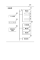
- FIG. 1 shows a block diagram of an image pickup apparatus 100 according to the first embodiment of the present invention.
- FIG. 1 is a block diagram of an image pickup apparatus 100 according to the first embodiment of the present invention.
- the image pickup apparatus 100 includes an image pickup unit 10, a processing circuit 20, a storage circuit 30, an input circuit 40, a display 50, an image storage circuit 60, and an internal bus 70.
- the image pickup unit 10 includes a lens 1, a line sensor R, a line sensor G, and a line sensor B.
- the imaging unit 10 acquires an image via the lens 1.
- the imaging unit 10 acquires an image of a marker described later via the lens 1 and has two or more line sensors (line sensor R, line sensor G, and line sensor B) that have color filters of different colors for each color.
- the marker is imaged by.
- the line sensor R has a red (R) color filter.
- the line sensor G has a green (G) color filter.
- the line sensor B has a blue (B) color filter.
- the line sensors (line sensor R, line sensor G, and line sensor B) each perform photoelectric conversion.
- Each of the line sensors (line sensor R, line sensor G, and line sensor B) one-dimensionally reads the amount of light that has passed through the filter of each color, converts it into an electrical signal, and outputs it.
- the processing circuit 20 is a processor that realizes the function corresponding to the program by reading the program from the memory (memory circuit 30) and executing the program. Specifically, the processing circuit 20 (processor) realizes the functions of the calculation unit 21 and the calibration unit 22 by executing the read program.
- the calculator 21 disperses the wavelength of the marker by the lens 1, and calculates the shift amount of the imaging pixel between the one or more line sensors (the line sensor R, the line sensor G, and the line sensor B) that have been dispersed. For example, when the predetermined G channel imaged by the line sensor G is used as a reference, the calculation unit 21 calculates the deviation amount between the image pickup pixels of the predetermined R channel imaged by the line sensor R and the predetermined G channel, and the line. A shift amount between image pickup pixels of a predetermined B channel and a predetermined G channel imaged by the sensor B is calculated.
- the calibrating unit 22 includes line sensors (line sensor R, line sensor R) of each of the three line sensors (line sensor R, line sensor G, and line sensor B) based on the shift amount of the imaging pixel calculated by the calculating unit 21.
- the calibration is performed so that the image pickup pixels imaged by G and the line sensor B) match.
- calibration means calibration. That is, for example, the calibration unit 22 sets the deviation amount of the predetermined R channel imaged pixel and the predetermined B channel imaged pixel calculated by the calculation unit 21 so as to match the predetermined G channel imaged pixel. Calibrate.
- FIG. 2 is an explanatory diagram showing lateral chromatic aberration due to the refractive index of the lens 1.
- the lens 1 transmits light to form an image on the imaging surface IS.
- the refractive index of light differs depending on the wavelength. Therefore, the light obliquely incident on the optical axis AX forms images at different positions on the imaging surface IS. Therefore, color shift occurs around the image distant from the optical axis AX.
- the red wavelength light RL forms a red image height HR on the imaging surface IS via the lens 1.
- the light GL of the green wavelength forms the green image height HG on the imaging surface IS via the lens 1.
- the light BL having a blue wavelength forms a blue image height HB on the imaging surface IS via the lens 1.
- the light of each wavelength (light RL, light GL, and light BL) is imaged at different positions, the color of the image is shifted, and the image is shifted. May be bleeding.
- image color shift and image color bleeding is generally called lateral chromatic aberration.
- the calculation unit 21 of the processing circuit 20 calculates the shift amount of the imaging pixel due to the lateral chromatic aberration, and the calibration unit 22 of the processing circuit 20 calculates the calculated imaging pixel. Based on the shift amount, the calibration is performed so that the imaged imaged pixels match.
- the word processor that constitutes the processing circuit 20 is, for example, a dedicated or general-purpose CPU (Central Processing Unit), an application-specific integrated circuit (ASIC), a programmable logic device (for example, simple programmable).
- a circuit such as a logic device (Simple Programmable Logic Device: SPLD), a complex programmable logic device (CPLD), and a field programmable gate array (FPGA) is meant.
- the processor realizes each function by reading and executing the program stored in the memory or directly installed in the circuit of the processor.
- the memory for storing the program may be provided individually for each processor, or the memory circuit 30 of FIG. 1 stores the program corresponding to the function of each processor. It doesn't matter.
- the storage circuit 30 is configured by a storage device including a ROM (Read Only Memory), a RAM (Random Access Memory), an HDD (Hard Disk Drive), and the like.
- the memory circuit 30 is used for storing IPL (Initial Program Loading), BIOS (Basic Input / Output System) and data, used as a work memory of the processing circuit 30, or temporarily storing data. Be done.
- the HDD is a storage device that stores a program (an OS (Operating System) or the like other than an application program) installed in the imaging device 100 and data. Further, it is possible to provide the OS with a GUI (Graphical User Interface) that uses graphics frequently for displaying information on the display 50 to the operator and can perform basic operations by the input circuit 40.
- GUI Graphic User Interface
- the input circuit 40 is a circuit that inputs a signal from an input device such as an operation button, a keyboard, a pointing device (mouse, etc.) that can be operated by an operator, and here, the input device itself is also included in the input circuit 40. And In this case, an input signal according to the operation is sent from the input circuit 40 to the processing circuit 20.
- an input device such as an operation button, a keyboard, a pointing device (mouse, etc.) that can be operated by an operator, and here, the input device itself is also included in the input circuit 40.
- an input signal according to the operation is sent from the input circuit 40 to the processing circuit 20.
- the display 50 is a display device having a function of displaying a captured image captured by the image capturing unit 10.
- the display 50 includes an image synthesizing circuit, a VRAM (Video Random Access Memory), a screen, and the like, which are not shown.
- VRAM Video Random Access Memory
- the image storage circuit 60 is configured to, for example, correct a captured image captured by the image capturing unit 10 with correction data based on calibration and store the corrected image.
- the image storage circuit 70 is composed of a storage circuit including, for example, a RAM and an HDD.
- the internal bus 70 is connected to each component so that the image pickup apparatus 100 is centrally controlled by the processing circuit 20.
- the internal bus 70 is composed of, for example, a circuit for transmitting data and signals in the imaging device 100.
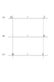
- FIG. 3 is an explanatory diagram showing an example of a marker imaged by the imaging device 100.
- markers marker MA1, marker MA2, and marker MA3
- FIG. 3A an example in which markers (marker MA1, marker MA2, and marker MA3) are provided at substantially the left and right ends and the center of the calibration area CA1 for executing the calibration of the chart CH1.
- FIG. 3B shows an example in which the markers (marker MA1 and marker MA2) are provided at substantially the left and right ends of the calibration area CA2 for executing the calibration of the chart CH2.
- FIG. 3C shows an example in which the marker (marker MA4) is provided in a predetermined range of the calibration area CA3 for executing the calibration of the chart CH3.
- the markers (markers MA1 to MA4) are formed by white and black lines.
- the chart is provided with a marker, but the present embodiment is not limited to this.
- the chart may be a test chart, contrast or energy.
- embossed unevenness is also applicable.
- Each marker (marker MA1 to marker MA4) has a white and black line of 2 to 10 pixels in the vertical direction.
- “upper” means the upper direction in each drawing
- “right” means the right direction in each drawing.
- FIG. 3C will be described in the second embodiment.
- a chart CH1 is shown in FIG.
- the chart CH1 has a calibration area CA1 for executing calibration.
- the chart CH1 is provided with markers MA1, MA2, and MA3 at substantially the left and right ends and substantially the center of the calibration area CA1.
- the “substantial end portion” includes the end portion of the calibration area CA1, and means, for example, an area provided within 100 pixels from the left and right ends of the calibration area CA1.
- the substantially center means, for example, a region within 10 pixels on the left and right of the center of the chart CH1 including the center of the calibration region CA1.
- the image capturing unit 10 of the image capturing apparatus 100 acquires the captured images of the marker MA1, the marker MA2, and the marker MA3 in the calibration area CA1 when the chart CH1 is captured.
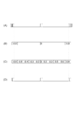
- FIG. 4 shows the imaging pixels acquired by the imaging device 100.
- FIG. 4 is an explanatory diagram showing image pickup pixels of the marker MA1, the marker MA2, and the marker MA3 in the calibration area CA1 imaged by the three line sensors (line sensor R, line sensor G, and line sensor B).
- 4A shows the image pickup pixels imaged by the line sensor R
- FIG. 4B shows the image pickup pixels imaged by the line sensor G
- FIG. 4C shows the line sensor B. The imaging pixel which imaged is shown.
- the image pickup pixel imaged by the line sensor R is displaced outward from the image pickup pixel imaged by the line sensor G of FIG. 4B.
- the image pickup pixel imaged by the line sensor B is displaced inward from the image pickup pixel imaged by the line sensor G of FIG. 4B. That is, FIG. 4 shows a pixel shift of lateral chromatic aberration.
- the calculation unit 21 of the processing circuit 20 according to the first embodiment of the present invention calculates the shift amount of the imaging pixel between one or more line sensors (line sensor R, line sensor G, and line sensor B). ..
- the calibration unit 22 of the processing circuit 20 according to the first embodiment of the present invention uses each of the three line sensors (the line sensor R, the line sensor G, and the line sensor B) based on the calculated image pickup pixel. Calibration is performed so that the image pickup pixels picked up by the line sensor match.
- the calculation unit 21 calculates the shift amount of the imaging pixels between the line sensors (the line sensor R and the line sensor G), and the calibration unit 22 images the imaging pixels imaged by the line sensor R by the line sensor G. It is explanatory drawing which showed the method of performing a calibration so that it may match with the image picked-up pixel.
- FIG. 5A shows the pixel shift between the image pickup pixel (solid line) imaged by the line sensor R and the image pickup pixel (dotted line) imaged by the line sensor G.
- the image pickup pixel indicated by the solid line is an image pickup pixel imaged by the line sensor R, and swells outside than the image pickup pixel imaged by the line sensor G indicated by the broken line.
- the calculation unit 21 of the processing circuit 20 calculates the amount of deviation between the image pickup pixel of the line sensor R and the image pickup pixel of the line sensor G.
- FIG. 5B shows the amount of deviation between the image pickup pixel imaged by the line sensor R and the image pickup pixel imaged by the line sensor G.
- the center of FIG. 5 (B) is a position corresponding to the marker MA3 (see FIG. 3 (A)), and shows the approximate center of the chart CH1.
- the marker MA3 (see FIG. 3A) is “0” when there is no shift in the image pickup pixel as the alignment of the substantially center of the chart CH1.
- the calibration can be appropriately executed.
- the position of the marker MA3 is Can be set as a substantially central position.
- the marker MA3 is not limited to the substantially center position, and even if the marker MA3 is actually deviated from the substantially center position, the position of the marker MA3 can be intentionally used as a positioning marker.
- FIG. 5B the left side of FIG. 5B is the position corresponding to the marker MA1 (see FIG. 3A), and the image pickup pixel imaged by the line sensor R is the image pickup pixel imaged by the line sensor G. On the other hand, it is shifted outward by "-0.8" pixels.
- the right side of FIG. 5B is a position corresponding to MA2 (see FIG. 3A), and the image pickup pixel imaged by the line sensor R is “0” with respect to the image pickup pixel imaged by the line sensor G. .8 ”pixels are shifted outward.
- the calculation unit 21 of the processing circuit 20 can calculate, for example, the amount of deviation from the image pickup pixels of the marker MA3 to the image pickup pixels of the marker MA1 by interpolation.
- the calculation unit 21 can calculate the shift amount from the image pickup pixel of the marker MA3 to the image pickup pixel of the marker MA2 by interpolation.
- the calculation unit 21 moves toward the left side from the center of FIG. 5C, and at the predetermined position, “ ⁇ 0.2, ⁇ 0.3, ⁇ 0.4, ⁇ 0.6, ⁇ , 0.8 ”and the shift amount of the image pickup pixel are calculated by interpolation.
- the calculation unit 21 picks up “0.2, 0.3, 0.5, 0.6, 0.8” at a predetermined position as moving from the center of FIG. The pixel shift amount is calculated by interpolation.
- the calculation unit 21 can calculate the shift amount of the image pickup pixel between the line sensor R and the line sensor G by interpolation at a predetermined position.
- the calibration unit 22 can perform calibration based on the calculated shift amount of the image pickup pixels so that the image pickup pixels imaged by the line sensors R and G match. it can.
- the calibration unit 22 shifts the image pickup pixel imaged by the line sensor R based on the shift amount of FIG. 5C, and thus the image is picked up by the line sensor G as shown in FIG. 5D. It is possible to match the image pickup pixel with the image pickup pixel. After performing the calibration in this way, the calibration unit 22 stores the shift amount of FIG. 5C as the correction data in the storage circuit 30 or the image storage circuit 60.
- the calculation unit 21 calculates the shift amount of the image pickup pixels between the line sensors (the line sensor B and the line sensor G), and the calibration unit 22 takes the image pickup pixels of the line sensor B by the line sensor G. It is explanatory drawing which showed the method of performing a calibration so that it may match with the image picked-up pixel.
- FIG. 6A shows the pixel shift between the image pickup pixel (solid line) imaged by the line sensor B and the image pickup pixel (dotted line) imaged by the line sensor G.
- the image pickup pixel indicated by the solid line is an image pickup pixel imaged by the line sensor B, and is recessed inside the image pickup pixel imaged by the line sensor G indicated by the broken line.
- the calculation unit 21 of the processing circuit 20 calculates the amount of deviation between the image pickup pixel of the line sensor B and the image pickup pixel of the line sensor G.
- FIG. 6B shows the amount of deviation between the image pickup pixel imaged by the line sensor B and the image pickup pixel imaged by the line sensor G.
- the center of FIG. 6B is a position corresponding to the marker MA3 (see FIG. 3A) and is “0”, which means that the center positions match.
- the left side of FIG. 6B is the position corresponding to the marker MA1 (see FIG. 3A)
- the image pickup pixel imaged by the line sensor B is the image pickup pixel imaged by the line sensor G.
- it is shifted inward by "0.6" pixels.
- the right side of FIG. 6B is a position corresponding to the marker MA2 (see FIG.
- the calculation unit 21 of the processing circuit 20 can calculate, for example, the amount of deviation from the image pickup pixels of the marker MA3 to the image pickup pixels of the marker MA1 by interpolation.
- the calculation unit 21 can calculate the shift amount from the image pickup pixel of the marker MA3 to the image pickup pixel of the marker MA2 by interpolation.
- the calculation unit 21 proceeds to the left from the center of FIG. 6C, “0.2, 0.3, 0.4, 0.5, 0.6” is displayed at a predetermined position.
- the shift amount of the image pickup pixel is calculated by interpolation.
- the calculation unit 21 proceeds from the center of FIG. 6C to the right, “ ⁇ 0.2, ⁇ 0.3, ⁇ 0.4, ⁇ 0.5, ⁇ 0 at a predetermined position. .6 ”and the shift amount of the image pickup pixel are calculated by interpolation.
- the calculation unit 21 can calculate the shift amount of the image pickup pixel between the line sensor B and the line sensor G by interpolation at a predetermined position.
- the calibration unit 22 can perform the calibration based on the calculated shift amount of the image pickup pixels so that the image pickup pixels imaged by the line sensors B and G match. it can.
- the calibrating unit 22 shifts the image pickup pixels picked up by the line sensor B based on the shift amount of FIG. 6C, so that the line sensor G picks up an image as shown in FIG. 6D. It is possible to match the image pickup pixel with the image pickup pixel. After performing the calibration in this way, the calibration unit 22 stores the deviation amount of FIG. 6C as the correction data in the storage circuit 30 or the image storage circuit 60.
- the markers are provided at the left and right substantially end portions and substantially the center of the calibration area CA1.
- the embodiment is not limited to this.
- the marker MA3 provided substantially at the center can be deleted so that calibration is not executed.
- the marker MA3 indicates the approximate center of the chart 1, and when it is not necessary to perform the alignment of the center position of the chart 1, the execution of the calibration of the marker MA3 can be excluded.
- the marker MA3 since the marker MA3 is generally less likely to be displaced at the substantially central position, it may be executed once. Therefore, once the calibration is executed at the center position, it is possible to eliminate the execution of the calibration by assuming that the center positions are aligned thereafter, and reduce the time required for the calibration.
- the shift amount shown in FIGS. 5C and 6C is calculated by the calculation unit 21 of the processing circuit 20 between the line sensors (line sensor R and line sensor G, line sensor B and line sensor G).
- the shift amount is calculated by interpolation, for example, when the shift amount has linearity, it can be calculated by applying spline interpolation.
- the image pickup apparatus 100 includes the image pickup unit 10 and the processing circuit 20, and the processing circuit 20 includes the calculation unit 21 and the calibration unit 22. ..
- the calculation unit 21 disperses the wavelengths of the markers by the lens 1, calculates the amount of deviation of the imaged pixels between the separated line sensors, and the calibration unit 22 uses the amount of deviation of the imaged pixels calculated by the calculator 21. Based on this, the calibration is executed so that the image pickup pixels imaged by the line sensors R, G, and B are matched.
- the image pickup apparatus 100 can store the shift amount of the image pickup pixel as the correction data in the storage circuit 30 or the image storage circuit 60, the calibration is performed once. By generating the shift amount of the image pickup pixel as the correction data, when the normal image pickup is executed thereafter, the correction can be performed using the generated correction data.
- the image capturing apparatus 100 stores the displacement amount of the image capturing pixel as the calibration data, so that, for example, the marker is not captured, and the calibration is performed using the calibration data. You may do it.
- the calibration area CA1 shown in FIG. 3A is not limited to the number of pixels in the horizontal direction (horizontal direction). For example, when 4000 pixels are arranged in a line in the left-right direction (horizontal direction), the center 3000 pixels of the calibration area CA1 are used for imaging, and the remaining 1000 pixels other than the center are used as calibration pixels. May be used.
- the timing at which the image capturing apparatus 100 according to the first embodiment of the present invention captures an image of a marker is not particularly limited. For example, it is possible to take an image at an arbitrary timing when the user wants to execute the calibration. For example, the calibration may be performed once every day in the morning or at night, or when the lens 1 is replaced.
- Second Embodiment (Example 2 of Imaging Device)>
- a marker is provided in a predetermined range of the calibration area in which the calibration is executed, and the calculation unit sets the marker to 1 in a predetermined range of the calibration area in which the marker is provided.
- the calibration unit calculates the shift amount of the imaging pixels between the line sensors, and the calibration unit matches the imaging pixels imaged by the respective line sensors of the two or more line sensors in a predetermined range of the calibration area in which the marker is provided. It is an imaging device that performs calibration so as to perform.
- the calibration is executed so that the imaging pixels imaged by the respective line sensors of the two or more line sensors match in a predetermined range of the calibration region. Therefore, it is possible to perform more accurate calibration.
- a chart CH3 is shown in FIG. 3 (C).
- the chart CH3 has a calibration area CA3 for executing calibration. Further, the chart CH3 has markers provided in a predetermined range of the calibration area CA3.
- the predetermined range is the entire range of the calibration area CA3.
- the calculation unit 21 calculates the shift amount between one or more line sensors in the entire range of the calibration area CA3 provided with the marker MA4 (see FIG. 3C). Then, the calibration unit 22 is imaged by each of the line sensors R, G, and B in the entire range of the calibration area CA3 in which the marker MA4 (see FIG. 3C) is provided. Calibration is performed so that the imaging pixels match.
- the image pickup pixels picked up by the respective line sensors R, G, and B in the predetermined range of the calibration area CA3 are displayed. Calibration can be performed to match.
- the line sensor R, the line sensor G, and the line sensor B take images in a predetermined range of the calibration area CA3. It is possible to perform the calibration so that the image pickup pixels match. As a result, for example, the calibration of the lens 1 can be precisely performed, so that the accuracy of the captured image can be improved.
- the marker MA4 as a predetermined range of the calibration area CA3, it is possible to partially perform the calibration.
- the marker MA4 by arranging the marker MA4 at a position where it is desired to precisely perform the calibration, the calibration of that portion can be performed.
- An image pickup apparatus is the image pickup apparatus according to the first embodiment, in which a marker is provided on a movable subject, and an imaging unit images the marker provided on the moving subject. , An imaging device.
- the imaging unit images the marker provided on the moving subject, so that the calibration can be executed when the marker is detected on the subject. ..
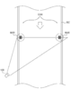
- FIG. 7 shows the overall configuration of the third embodiment according to the present invention.
- FIG. 7 is an explanatory diagram showing an embodiment in which the image pickup apparatus according to the third embodiment of the present invention images a belt conveyor which is a subject, and executes a calibration when a marker is detected in the calibration area. is there. Unless otherwise specified, “upper” means the upper direction in FIG. 7, and “right” means the right direction in FIG. 7.
- the belt conveyor BC has calibration areas CA4 on both sides of the belt conveyor BC. Markers (markers MA5 and MA6) are provided in the calibration area CA4.
- the belt conveyor BC is, for example, a vertical belt conveyor.
- the imaging device 100 images the belt conveyor BC at a predetermined timing.
- the belt conveyor BC is rotatingly moved from top to bottom, and when the imaging apparatus 100 detects the markers (markers MA5 and MA6) in the calibration area CA4 along with the rotation movement of the belt conveyor BC. , Calibrate.
- the imaging device 100 of the third embodiment of the present invention when the imaging unit 10 images the markers (marker MA5, marker MA6) provided on the moving belt conveyor BC. , Calibration can be performed. As a result, in the third embodiment, the calibration of the imaging device 100 can be automatically executed at the predetermined timing desired by the user.
- the image pickup apparatus 100 is applied to an inspection camera, and a marker (marker MA5 is provided in the calibration area CA4 of the belt conveyor BC in accordance with the timing of starting or ending the inspection.
- a marker marker MA5 is provided in the calibration area CA4 of the belt conveyor BC in accordance with the timing of starting or ending the inspection.
- the calibration can be executed at a desired predetermined timing.
- first to third embodiments according to the present invention are not limited to the above-described embodiments, and various modifications can be made without departing from the gist of the present invention.
- the image pickup apparatus 100 is configured to include the display 50 and the image storage circuit 60, but the present embodiment is not limited to this.
- the imaging device 100 may not include the display 50 and the image storage circuit 60, but may include a separate display or an external image storage circuit via a wired or wireless network.
- the imaging device 100 can store the captured image to be stored in the image storage circuit 60 in an external image storage circuit, or can display the captured image on a separate display.
- Image pickup unit 10 Image pickup unit 20 Processing circuit 21 Calculation unit 22 Calibration unit 30 Storage circuit 40 Input circuit 50 Display 60 Image storage circuit BC Belt conveyor CH1, CH2, CH3, CH4 Chart MA1, MA2, MA3, MA4 Marker R, G, B Line sensor
Landscapes
- Engineering & Computer Science (AREA)
- Multimedia (AREA)
- Signal Processing (AREA)
- Physics & Mathematics (AREA)
- General Physics & Mathematics (AREA)
- Theoretical Computer Science (AREA)
- Studio Devices (AREA)
- Image Input (AREA)
- Image Processing (AREA)
- Color Television Image Signal Generators (AREA)
Abstract
L'invention concerne un dispositif d'imagerie capable d'exécuter automatiquement un réglage compliqué pour un étalonnage pour une aberration chromatique de grossissement. Le dispositif d'imagerie est pourvu : d'une unité d'imagerie qui acquiert une image d'un marqueur à travers une lentille et capture une image du marqueur au moyen d'au moins deux capteurs de ligne comprenant des filtres de couleur de couleurs différentes pour chaque couleur ; d'une unité de calcul pour calculer une quantité de déplacement d'un ou plusieurs pixels d'imagerie entre les capteurs de ligne en raison de la dispersion spectrale, par la lentille, des longueurs d'onde du marqueur ; et d'une unité d'étalonnage pour exécuter un étalonnage, sur la base de la quantité de déplacement calculée des pixels d'imagerie, de sorte que les pixels d'imagerie capturés par les capteurs de ligne respectifs des au moins deux capteurs de ligne coïncident.
Priority Applications (1)
| Application Number | Priority Date | Filing Date | Title |
|---|---|---|---|
| CN201980086945.0A CN113228629A (zh) | 2018-11-16 | 2019-10-31 | 摄像装置 |
Applications Claiming Priority (2)
| Application Number | Priority Date | Filing Date | Title |
|---|---|---|---|
| JP2018215577A JP2020086578A (ja) | 2018-11-16 | 2018-11-16 | 撮像装置 |
| JP2018-215577 | 2018-11-16 |
Publications (1)
| Publication Number | Publication Date |
|---|---|
| WO2020100623A1 true WO2020100623A1 (fr) | 2020-05-22 |
Family
ID=70730626
Family Applications (1)
| Application Number | Title | Priority Date | Filing Date |
|---|---|---|---|
| PCT/JP2019/042880 Ceased WO2020100623A1 (fr) | 2018-11-16 | 2019-10-31 | Dispositif d'imagerie |
Country Status (3)
| Country | Link |
|---|---|
| JP (1) | JP2020086578A (fr) |
| CN (1) | CN113228629A (fr) |
| WO (1) | WO2020100623A1 (fr) |
Citations (3)
| Publication number | Priority date | Publication date | Assignee | Title |
|---|---|---|---|---|
| JPH1042157A (ja) * | 1996-07-26 | 1998-02-13 | Canon Inc | 画像処理方法とその装置 |
| JP2000092335A (ja) * | 1998-09-14 | 2000-03-31 | Minolta Co Ltd | 画像読取装置および色収差補正方法 |
| JP2003143421A (ja) * | 2001-11-01 | 2003-05-16 | Sharp Corp | 画像処理装置および画像処理方法 |
Family Cites Families (4)
| Publication number | Priority date | Publication date | Assignee | Title |
|---|---|---|---|---|
| JPH10257254A (ja) * | 1997-01-07 | 1998-09-25 | Minolta Co Ltd | 画像読み取り装置 |
| JP2000134483A (ja) * | 1998-10-26 | 2000-05-12 | Minolta Co Ltd | 画像読取装置 |
| JP4138324B2 (ja) * | 2001-11-28 | 2008-08-27 | 松下電器産業株式会社 | ズームレンズ及びそれを用いたビデオカメラ |
| JP5627215B2 (ja) * | 2009-11-04 | 2014-11-19 | キヤノン株式会社 | 画像処理装置及びその制御方法 |
-
2018
- 2018-11-16 JP JP2018215577A patent/JP2020086578A/ja active Pending
-
2019
- 2019-10-31 CN CN201980086945.0A patent/CN113228629A/zh active Pending
- 2019-10-31 WO PCT/JP2019/042880 patent/WO2020100623A1/fr not_active Ceased
Patent Citations (3)
| Publication number | Priority date | Publication date | Assignee | Title |
|---|---|---|---|---|
| JPH1042157A (ja) * | 1996-07-26 | 1998-02-13 | Canon Inc | 画像処理方法とその装置 |
| JP2000092335A (ja) * | 1998-09-14 | 2000-03-31 | Minolta Co Ltd | 画像読取装置および色収差補正方法 |
| JP2003143421A (ja) * | 2001-11-01 | 2003-05-16 | Sharp Corp | 画像処理装置および画像処理方法 |
Also Published As
| Publication number | Publication date |
|---|---|
| CN113228629A (zh) | 2021-08-06 |
| JP2020086578A (ja) | 2020-06-04 |
Similar Documents
| Publication | Publication Date | Title |
|---|---|---|
| US20100245826A1 (en) | One chip image sensor for measuring vitality of subject | |
| JP5440615B2 (ja) | ステレオカメラ装置 | |
| JP2010271246A (ja) | 色彩輝度測定装置及び色彩輝度測定方法 | |
| JP7238296B6 (ja) | プロジェクター、色補正システム及びプロジェクターの制御方法 | |
| JP6013284B2 (ja) | 撮像装置及び撮像方法 | |
| JP6341335B2 (ja) | 二次元測色装置 | |
| CN101828404B (zh) | 分光特性校正装置、分光特性校正方法 | |
| JP2009141684A (ja) | 色変換係数算出装置、色変換係数算出プログラム、色変換係数算出方法 | |
| JP2010139324A (ja) | 色ムラ測定方法、および色ムラ測定装置 | |
| JP7172294B2 (ja) | プロジェクター、色補正システム、及びプロジェクターの制御方法 | |
| JP2006177812A (ja) | 二次元分光輝度計 | |
| JP2010190741A (ja) | 測定装置、測定方法および撮像装置 | |
| JP7428090B2 (ja) | 校正装置、校正方法、校正プログラム、及び分光カメラ | |
| WO2020100623A1 (fr) | Dispositif d'imagerie | |
| JP7491084B2 (ja) | 校正装置、校正方法、校正プログラム、分光カメラ、及び情報処理装置 | |
| JP6617537B2 (ja) | 2次元測色計、該方法および該プログラムならびに表示システム | |
| US20180234650A1 (en) | Image processing apparatus, image processing method, and computer readable recording medium | |
| US10778948B2 (en) | Imaging apparatus and endoscope apparatus | |
| CN105359517B (zh) | 图像处理装置和图像处理方法 | |
| JP2006292582A (ja) | マルチバンド画像処理装置及びその方法並びにマルチバンド画像撮像装置 | |
| WO2013111824A1 (fr) | Dispositif de traitement d'images, dispositif de capture d'images et procédé de traitement d'images | |
| JP2007147507A (ja) | 分光測定方法及び分光測定装置 | |
| JP2014103461A (ja) | 収差補正機能付き画像読取装置 | |
| JP5733706B2 (ja) | 画像処理装置、方法、及びプログラム | |
| WO2013111228A1 (fr) | Dispositif de détection de marqueur et procédé pour la détection d'un marqueur |
Legal Events
| Date | Code | Title | Description |
|---|---|---|---|
| 121 | Ep: the epo has been informed by wipo that ep was designated in this application |
Ref document number: 19884412 Country of ref document: EP Kind code of ref document: A1 |
|
| NENP | Non-entry into the national phase |
Ref country code: DE |
|
| 122 | Ep: pct application non-entry in european phase |
Ref document number: 19884412 Country of ref document: EP Kind code of ref document: A1 |