WO2020100902A1 - Dispositif et procédé d'estimation de position de lignes blanches - Google Patents
Dispositif et procédé d'estimation de position de lignes blanches Download PDFInfo
- Publication number
- WO2020100902A1 WO2020100902A1 PCT/JP2019/044362 JP2019044362W WO2020100902A1 WO 2020100902 A1 WO2020100902 A1 WO 2020100902A1 JP 2019044362 W JP2019044362 W JP 2019044362W WO 2020100902 A1 WO2020100902 A1 WO 2020100902A1
- Authority
- WO
- WIPO (PCT)
- Prior art keywords
- state
- lane
- white line
- vehicle
- related state
- Prior art date
- Legal status (The legal status is an assumption and is not a legal conclusion. Google has not performed a legal analysis and makes no representation as to the accuracy of the status listed.)
- Ceased
Links
Images




Classifications
-
- B—PERFORMING OPERATIONS; TRANSPORTING
- B60—VEHICLES IN GENERAL
- B60W—CONJOINT CONTROL OF VEHICLE SUB-UNITS OF DIFFERENT TYPE OR DIFFERENT FUNCTION; CONTROL SYSTEMS SPECIALLY ADAPTED FOR HYBRID VEHICLES; ROAD VEHICLE DRIVE CONTROL SYSTEMS FOR PURPOSES NOT RELATED TO THE CONTROL OF A PARTICULAR SUB-UNIT
- B60W30/00—Purposes of road vehicle drive control systems not related to the control of a particular sub-unit, e.g. of systems using conjoint control of vehicle sub-units
- B60W30/10—Path keeping
- B60W30/12—Lane keeping
-
- G—PHYSICS
- G08—SIGNALLING
- G08G—TRAFFIC CONTROL SYSTEMS
- G08G1/00—Traffic control systems for road vehicles
- G08G1/16—Anti-collision systems
Definitions
- the present disclosure relates to a white line position estimation device and a white line position estimation method.
- a white line is recognized based on a captured image captured by a camera that captures the front of the vehicle, and the traveling of the vehicle is controlled based on the white line (for example, see Patent Document 1).
- the vehicle travel is controlled based on the conditions of the white line and the surrounding vehicles traveling around the host vehicle. Is required. Therefore, it is required to specify the lane position of an object around the host vehicle as information used for vehicle driving control.
- the white line cannot be recognized due to a malfunction of the camera that images the front of the vehicle, the position of the white line cannot be specified, and the lane position of an object around the vehicle cannot be specified. Therefore, even if the white line cannot be recognized, it is required to be able to estimate the position of the white line although the reliability is reduced.
- the present disclosure has been made in view of these points, and a white line position estimation device and a white line position estimation method that can hold the white line position information without being lost even when the white line cannot be recognized.
- the purpose is to provide.
- a white line position estimating device is based on information indicating the front of the host vehicle, the positional relationship between the host vehicle and the white line corresponding to the lane in which the host vehicle is traveling, and the curvature of the white line.
- a lane-related state specifying unit that specifies a lane-related state indicating a lane width
- a motion state detecting unit that detects a motion state of the own vehicle
- the lane-related state is specified by the lane-related state specifying unit and
- the position of the white line within a predetermined range from the own vehicle is estimated at predetermined intervals based on the lane-related condition and the motion condition, and the lane-related condition is estimated.
- the lane-related state is not specified by the state specifying unit and the movement state is detected by the movement state detection unit
- the lane-related state is estimated by estimating the positional relationship based on the movement state.
- the white line position estimating unit that estimates the position of the white line at the predetermined time intervals based on the estimated lane-related state and the motion state.
- the white lane position estimation unit when the lane-related state is specified by the lane-related state specifying unit, when the lane-related state is not specified, when the lane-related state is not specified, the lane-related state is not specified.
- the position of the white line may be estimated based on the past lane-related state that is the lane-related state specified before the change, the lane-related state estimated based on the exercise state, and the exercise state.
- the white line position estimation unit estimates the position of the white line by increasing the influence degree of the lane-related state estimated based on the motion state while reducing the influence degree of the past lane-related state as time passes. May be.
- the white line position estimation unit if the lane-related state is not specified by the lane-related state specifying unit, and the movement state is not detected by the movement state detection unit, the movement state of the own vehicle, While estimating the motion state when the host vehicle is traveling at a constant speed on a straight line, the lane-related state is estimated and estimated as the lane-related state when the host vehicle is traveling on the center of a straight road.
- the position of the white line may be estimated based on the lane-related state and the estimated motion state.
- the lane line position estimating unit determines whether the lane-related state is not specified by the lane-related state specifying unit and the movement state is detected by the movement-state detecting unit, and the lane-related state specifying unit determines the lane-related state.
- the state is not specified and the exercise state is changed to a state in which the exercise state is not detected by the exercise state detection unit, a past exercise state that is the exercise state detected before the change in the exercise state is detected.
- the position of the white line may be estimated based on the estimated motion state and the estimated lane-related state.
- the white line position estimation unit may estimate the position of the white line by decreasing the influence degree of the past exercise state and increasing the estimated influence degree of the exercise state over time.
- the white line position estimating unit based on the specific situation of the lane-related state in the lane-related state identifying unit, and the detection situation of the exercise state in the exercise state detection unit, the reliability of the position of the estimated white line It may be calculated.
- a white line position estimating method is based on a positional relationship between a white line corresponding to a lane in which the vehicle is traveling and the vehicle based on information indicating a front of the vehicle executed by a computer. , A step of identifying a lane-related state indicating the curvature and a lane width of the white line, a step of detecting a motion state of the own vehicle, and a case in which the lane-related state is specified and the motion state is detected.
- Estimating the position of the white line within a predetermined range from the own vehicle at predetermined intervals based on the lane-related state and the exercise state, when the lane-related state is not specified and the exercise state is detected A step of estimating the lane-related state by estimating the positional relationship based on the motion state, and estimating the position of the white line at the predetermined time intervals based on the estimated lane-related state and the exercise state; , Is provided.
- the position information of the white line can be retained without being lost.
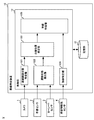
- FIG. 1 is a diagram illustrating an outline of the lane identification device according to the present embodiment.
- FIG. 2 is a diagram schematically showing the internal configuration of the vehicle according to the present embodiment.
- FIG. 3 is a diagram showing the relationship between the X axis and the Y axis in the vehicle coordinate system.
- FIG. 4 is a diagram showing an example in which the white line position identifying unit according to the present embodiment calculates a plurality of white line coordinates in front of the vehicle.
- FIG. 5A is a diagram showing an example in which the white line position identifying unit according to the present embodiment calculates a plurality of white line coordinates behind the vehicle.
- FIG. 1 is a diagram illustrating an outline of the lane identification device according to the present embodiment.
- FIG. 2 is a diagram schematically showing the internal configuration of the vehicle according to the present embodiment.
- FIG. 3 is a diagram showing the relationship between the X axis and the Y axis in the vehicle coordinate system.
- FIG. 4 is a diagram
- FIG. 5B is a diagram showing an example in which the white line position identifying unit according to the present embodiment calculates a plurality of white line coordinates behind the vehicle.
- FIG. 6 is a diagram illustrating a method of calculating a lateral displacement and an azimuth based on a vehicle motion state according to the present embodiment.
- FIG. 7 is a flowchart showing the flow of processing in the lane identifying apparatus according to this embodiment.
- FIG. 1 is a diagram illustrating an outline of the lane identification device 10 according to the present embodiment.
- the lane identification device 10 is, for example, a computer mounted on the vehicle V.
- the lane identification device 10 is a device that identifies a lane in which a peripheral vehicle OV, which is an object around the vehicle V as the host vehicle, is traveling.
- the object around the vehicle V is described as the peripheral vehicle OV traveling around the vehicle V, but the present invention is not limited to this.
- the object around the vehicle V may be a peripheral vehicle OV stopped around the vehicle V or an obstacle such as a person, an animal, or a falling object.
- the vehicle V is equipped with a camera that captures an area AC in front of the traveling direction of the vehicle V.
- the lane identification device 10 functions as a white line position identification device, and based on the image of the area AC captured by the camera, the positional relationship between the white line corresponding to the lane in which the vehicle V is traveling and the vehicle V, the curvature of the white line, and the lane width.
- the vehicle speed and yaw rate which are the motion states of the vehicle V, are detected while the lane-related state indicating the above is specified.
- the lane identification device 10 When the lane identification device 10 can identify the lane-related state and can detect the motion state of the vehicle V, the lane identification device 10 detects the white lines before and after the vehicle V based on the lane-related state and the motion state of the vehicle V. Estimate the position. When the lane identification device 10 cannot detect the lane-related state due to a malfunction of the camera and can detect the motion state of the vehicle V, the white lines before and after the vehicle V are detected based on the motion state of the vehicle V. Estimate the position of. By doing so, the lane identification device 10 can estimate the position of the white line even if the white line cannot be recognized due to a malfunction of the camera or the like and the lane-related state cannot be identified.
- the vehicle V is equipped with one or more obstacle detection sensors for identifying the surrounding vehicle OV.
- the vehicle V is provided with six obstacle sensors.
- Each of the six obstacle sensors detects the surrounding vehicle OV as an obstacle in the areas AL1 to AL6 around the vehicle V.
- the lane identification device 10 identifies the positions of the left and right ends of the surrounding vehicle OV based on the detection situation of the surrounding vehicle OV in the surrounding areas AL1 to AL6 by the obstacle detection sensor.
- the lane identification device 10 identifies the lane in which the peripheral vehicle OV is traveling based on the estimated position of the white line and the positions of the vertices of the identified peripheral vehicle OV. By doing so, the lane identification device 10 can identify the situation of the surrounding vehicle OV traveling around the vehicle V and can assist the safe lane change.
- the lane identification device 10 will be described in detail below.
- FIG. 2 is a diagram schematically showing the internal configuration of the vehicle V according to the present embodiment.
- the vehicle V includes a camera 1, a vehicle speed sensor 2, a yaw rate sensor 3, an obstacle detection sensor 4, and a lane identifying device 10.
- the camera 1 is provided at the front of the vehicle V.
- the camera 1 is provided, for example, at the center position of the vehicle V in the width direction.
- the camera 1 photographs the front of the vehicle V.
- the camera 1 captures the front of the vehicle V by capturing an image of the front of the vehicle V at predetermined time intervals (for example, tens to hundreds of milliseconds), and outputs an image to the lane identifying device 10.
- the vehicle speed sensor 2 detects the speed of the vehicle V.
- the vehicle speed sensor 2 outputs speed information indicating the detected speed of the vehicle V to the lane identifying device 10.
- the yaw rate sensor 3 detects a yaw rate generated in the vehicle V.
- the yaw rate generated in the vehicle V is the speed of the yaw angle of the vehicle V.
- the yaw rate sensor 3 outputs yaw rate information indicating the detected yaw rate to the lane identifying device 10.
- the obstacle detection sensor 4 is, for example, a LIDAR (Light Detection And Ranging), which emits an electromagnetic wave around the vehicle V and receives an electromagnetic wave reflected from the surrounding vehicle OV as an obstacle to detect the surrounding vehicle OV. To detect.
- LIDAR Light Detection And Ranging
- the lane identification device 10 includes a storage unit 11 and a control unit 12.
- the storage unit 11 is, for example, a ROM (Read Only Memory) or a RAM (Random Access Memory).
- the storage unit 11 stores various programs for causing the control unit 12 to function.
- the control unit 12 is a calculation resource including a processor such as a CPU (Central Processing Unit) (not shown).
- the control unit 12 executes the programs stored in the storage unit 11 so that the lane-related state identifying unit 121, the motion state detecting unit 122, the white line position estimating unit 123, the object identifying unit 124, and the lane identifying unit 125 can be used. Function.
- the lane identification device 10 functions as a white lane position estimation device by including the lane related state identification unit 121, the motion state detection unit 122, and the white line position estimation unit 123, and the vehicle V corresponding to the lane in which the vehicle V is traveling. Estimate the white line positions before and after.
- the vehicle coordinate system which is the coordinate system used in this embodiment, will be described.
- FIG. 3 is a diagram showing the relationship between the X axis and the Y axis in the vehicle coordinate system.
- a vehicle coordinate system is defined in which the center in the width direction of the forefront portion of the vehicle V, which is the mounting position of the camera 1, is the origin, and the X axis is in the right hand direction of the vehicle and the Y axis is in the front direction of the vehicle.
- the white line indicates a lane marker or the like in addition to a solid line or a broken line that divides the lane in which the vehicle V is traveling.
- the lane-related state identification unit 121 based on the image captured by the camera 1 as information indicating the traveling environment in front of the vehicle V, the positional relationship between the white line corresponding to the lane in which the vehicle V is traveling and the vehicle V, the white line A lane-related state indicating a curvature, a lane width, and the like is specified.
- the lane-related state identification unit 121 identifies the lane-related state by identifying a state variable indicating the lane-related state.
- the lane-related state identification unit 121 makes a lateral displacement Uc from the center of the vehicle V to the center of the lane, a tangent line of the white line, and the Y-axis, as state variables indicating the positional relationship between the white line and the vehicle V.
- the azimuth angle ⁇ of the vehicle V which is the angle, is specified.
- the lane-related state identification unit 121 identifies the curvature ⁇ of the white line, the rate of change ⁇ of the curvature of the white line in the vehicle front direction, and the lane width W as state variables.
- the motion state detection unit 122 detects the motion state of the vehicle V. Specifically, the motion state detection unit 122 detects the speed as the motion state of the vehicle V by acquiring speed information indicating the speed of the vehicle V from the vehicle speed sensor 2. Further, the exercise state detection unit 122 detects the yaw rate as the exercise state of the vehicle V by acquiring the yaw rate information indicating the yaw rate of the vehicle V from the yaw rate sensor 3.
- the white line position estimation unit 123 determines the state variable and the state variable. The positions of the white lines before and after the vehicle V within a predetermined range from the vehicle V are estimated at predetermined time intervals based on the motion state.
- the white line position estimating unit 123 uses the lateral displacement Uc, the lane width W, the azimuth angle ⁇ , the curvature ⁇ of the white line, and the rate of change ⁇ of the curvature, which are identified by the lane related state identifying unit 121.
- the white line coordinates in front of the vehicle V are calculated. Assuming that the position in front of the vehicle is Y i , the X coordinate of the white line on the left side at the position Y i is X Li , and the X coordinate of the white line on the right side is X Ri , X Li and X Ri are, for example, a white line shape by a cubic curve. By approximating, it is shown by the following formulas (1) and (2).
- Y Li indicating the Y coordinate of the white line on the left side
- Y Ri indicating the Y coordinate of the white line on the right side
- the white line shape is defined by a quadratic curve for Y Li or Y Ri without considering the term of the rate of change ⁇ of curvature shown in Expressions (1) and (2). You may approximate.
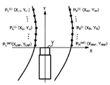
- FIG. 4 is a diagram showing an example in which the white line position estimation unit 123 according to the present embodiment calculates a plurality of white line coordinates in front of the vehicle.
- the white line position estimation unit 123 goes from the front of the vehicle V toward the rear, and the position coordinates P L (i) (X Li , Y Li ) of the left white line (where i is 1 to 1).
- N F ) and the position coordinates P R (i) (X Ri , Y Ri ) of the right white line are calculated to calculate the white line coordinates in front of the vehicle.
- N F is the number of points on the front left white line or right white line.
- the white line position estimation unit 123 calculates the white line coordinates behind the vehicle V using the lateral position and the lane width of the lane-related states and the motion state of the vehicle V.
- 5A and 5B are diagrams showing an example in which the white line position estimation unit 123 according to the present embodiment calculates a plurality of white line coordinates behind the vehicle.
- each coordinate value at time step k + 1 can be expressed as in the following equations (3) and (4) by two-dimensional coordinate conversion using each coordinate value at time step k.
- the equation (3) corresponds to the coordinate transformation of the left rear white line
- the equation (4) corresponds to the coordinate transformation of the right rear white line.
- ⁇ is the amount of change in the yaw angle of the vehicle V between time steps.
- the white line position estimation unit 123 calculates, as ⁇ , a product of the yaw rate ⁇ k of the vehicle V detected by the motion state detection unit 122 and the time increment ⁇ t k between time steps.
- the coordinates (X k D , Y k D ) are the camera position after the time increment ⁇ t k between time steps as viewed from the vehicle coordinate system at time step k, that is, the movement destination of the origin of the vehicle coordinate system. ..
- the white line position estimation unit 123 calculates the coordinates (X k D , Y k D ) by autonomous navigation using the velocity v k of the vehicle V detected by the motion state detection unit 122 and the yaw rate ⁇ k of the vehicle V. .. Then, when the white line position estimation unit 123 calculates ⁇ and the coordinates (X k D , Y k D ), it calculates each coordinate value at the time step k + 1 based on the equations (3) and (4).
- the white line position estimation unit 123 calculates the coordinates corresponding to each point on the back white line at time k + 1 based on the following equations (5) to (8).
- equations (5) and (6) represent the generation of a new point just beside the front of the vehicle.
- U Lk and U Rk are lateral displacements up to the left white line and the right white line, respectively, estimated at the time step k, and the lateral displacements at the time step k are represented by the following equations (9) and (10). It is calculated based on U Ck and lane width W k .
- Equation (7) shows the coordinate transformation associated with the vehicle motion for the existing left rear white line point
- Equation (8) shows the coordinate transformation associated with the vehicle motion for the existing right rear white line point.
- N B is the number of points on the left or right white line on the rear side.
- the distance of the lane behind which the lane determination is performed is, for example, up to about 300 m from the front of the vehicle. Therefore, when performing the above calculation, the white line position estimation unit 123 deletes points whose distance from the vehicle front surface is equal to or greater than a predetermined threshold value after updating the coordinates of the rear point at each time step. ..
- the lane-related state identification unit 121 cannot identify the lane-related state due to a defect of the camera 1, or when the exercise state detection unit 122 cannot detect the exercise state due to a defect of the vehicle speed sensor 2 or the yaw rate sensor 3 or the like. There is.
- the white line position estimating unit 123 sets the state variable indicating the lane-related state as a state variable.
- the included lane width is regarded as a predetermined width, and the lane-related state is estimated by estimating the positional relationship between the white line and the vehicle V based on the motion state. Then, the white line position estimation unit 123 estimates the position of the white line at predetermined intervals based on the estimated lane-related state and motion state.
- the white lane position estimating unit 123 does not specify the lane-related state when the lane-related state specifying unit 121 changes the state in which the lane-related state is specified to a state in which the lane-related state is not specified.
- the state variable specified last is the past state variable.
- the white line position estimation unit 123 estimates the position of the white line based on the past state variable, the state variable estimated based on the exercise state detected by the exercise state detection unit 122, and the exercise state.
- the white line position estimating unit 123 estimates the position of the white line by decreasing the influence degree of the past state variable and increasing the influence degree of the state variable estimated based on the motion state as time passes.
- FIG. 6 is a diagram illustrating a method of calculating the lateral displacement Uc and the azimuth angle ⁇ according to the present embodiment.
- the vehicle moves from the front center of the vehicle V to the vehicle.
- the angle formed by the line extending toward the center of gravity P of V and the tangent to the arc on the front surface of the vehicle V is the azimuth angle ⁇ .
- a predetermined width for example, 3.5 m
- the white line position estimation unit 123 sets the past state variable as A 3 , and the state variable estimated or regarded as a predetermined value based on the motion state as A 2, and each state variable A at time t based on the following equation (11). Calculate new .
- w 2 and w 3 are weighting factors indicating the degree to which A 2 and A 3 are applied to the calculation of the X coordinate of the white line.
- the white line position estimation unit 123 uses the weighting factors w 2 and w corresponding to each time based on the following equations (12) and (13) until the value of w 2 becomes 1 and the value of w 3 becomes 0. Update 3 .
- ⁇ t is a time step
- ⁇ is a coefficient indicating the speed at which the weighting coefficient is updated.
- the white line position estimation unit 123 may change ⁇ based on the tendency of steering or acceleration / deceleration of the vehicle V. For example, the white line position estimation unit 123 may increase the value of ⁇ when the vehicle V tends to be steered more frequently than when the vehicle V is not steered frequently.
- the white line position estimation unit 123 calculates Equations (1) to (10) by using the state variable A new at each time calculated based on Equations (11) to (13) and the detected motion state,
- the lane-related state identification unit 121 does not identify the lane-related state and the movement state detection unit 122 changes to a state in which the movement state is detected
- the X coordinate of the front and rear white line of the vehicle V at each time is calculated.
- the state variable is specified and the motion state is detected from the state in which the lane-related state specifying unit 121 does not specify the state variable and the motion state detecting unit 122 detects the motion state.
- the value of w 2 is set to 0 and the value of w 3 is set to 1 immediately after the change, and based on the specified state variable and the detected motion state, equations (1) to (10) Is calculated to calculate the X coordinate of the white line in front of and behind the vehicle V at each time.
- the white line position estimating unit 123 indicates the motion state of the vehicle V as a straight line. Is estimated as the motion state when the vehicle is traveling at a constant speed, and the state variable indicated by the lane-related state is estimated as the state variable when the vehicle V is traveling in the straight lane center. Then, the white line position estimation unit 123 estimates the position of the white line based on the estimated state variable and motion state.
- the state variable is not specified by the lane-related state specifying unit 121, and the state variable is not specified from the state in which the motion state is detected by the motion state detecting unit 122.
- the state has changed to a state in which the motion state has not been detected
- the motion state detected last among the motion states detected before the state has changed to the state in which the motion state has not been detected is defined as the past motion state.
- the white line position estimation unit 123 sets the last estimated state variable among the state variables estimated before the movement state is not detected as the past estimated state variable.
- the white line position estimation unit 123 estimates the position of the white line based on the past motion state, the past state variable, the estimated motion state, and the estimated state variable.
- the white line position estimation unit 123 estimates the position of the white line by decreasing the influence degree of the past motion state and the past estimated state variable and increasing the estimated influence degree of the motion state and the state variable over time.
- a predetermined speed for example, 60 km / h
- the white line position estimating unit 123 considers the case where the vehicle V is traveling in the center of a straight lane, and estimates the curvature ⁇ to be 0 m ⁇ 1 , the azimuth ⁇ to be 0 deg, and the lateral displacement Uc to be 0 m. Estimate variables.
- w 1 and w 2 are weighting factors indicating the degree to which B 1 and B 2 are applied to the calculation of the X coordinate of the white line.
- the white line position estimation unit 123 uses the weighting factor w 1 corresponding to each time based on the following equations (15) and (16) until the value of w 1 becomes 1 and the value of w 2 becomes 0. , W 2 are updated.
- ⁇ t is a time step
- ⁇ is a coefficient indicating the speed at which the weighting coefficient is updated.
- the white line position estimation unit 123 may change ⁇ based on the tendency of steering or acceleration / deceleration.
- the white line position estimating unit 123 calculates the equations (1) to (10) using the motion state and the state variable B new calculated at each time based on the equations (14) to (16), thereby calculating the lane-related state.
- the lane-related state is not identified by the identifying unit 121 and the exercising state is not detected by the exercising state detecting unit 122, the X coordinate of the front and rear white line of the vehicle V at each time is calculated.
- the state variable is not specified by the lane-related state specifying unit 121, and the motion variable is not detected by the motion state detecting unit 122.
- the value of w 1 is set to 0 and the value of w 2 is set to 1 immediately after the change, and based on the estimated state variable and the detected motion state, equations (1) to ( By calculating 10), the X coordinate of the white line in front of and behind the vehicle V at each time is calculated.
- the white line position estimation unit 123 indicates the reliability of the estimation accuracy of the white line position based on the lane-related state identification situation in the lane-related state identification unit 121 and the exercise state detection situation in the exercise state detection unit 122.
- a reliability value may be calculated as the reliability information.
- the confidence value is set to a numerical value from 1 to 3. When the reliability value is 3, the reliability is highest and the reliability decreases as the reliability value approaches 1.
- the white line position estimation unit 123 determines the reliability value. Set to 3. If the lane-related state identifying unit 121 has not identified the state variable indicating the lane-related state and the motion state detecting unit 122 has detected the motion state of the vehicle V, the reliability value is set to w 3 . The value obtained by adding 2 is used. If the lane-related state specifying unit 121 does not specify the state variable indicating the lane-related state and the motion state detecting unit 122 does not detect the motion state of the vehicle V, the reliability value is set to w 2 . Let 1 be the value added.
- the white line position estimating unit 123 may output the calculated reliability value to the lane identifying unit 125. By doing so, the certainty can be added to the lane in which the peripheral vehicle OV specified by the lane specifying unit 125 of the lane specifying device 10 is located.
- the lane identifying device 10 estimates the white line position to identify the lane in which the surrounding vehicle OV is located.
- the reliability value is set to 0.
- the white line position may not be estimated and the lane in which the surrounding vehicle OV is located may not be specified.
- the object identifying unit 124 identifies the positions of the four vertices of the rectangle and the center position of the rectangle when the surrounding vehicle OV as an object around the vehicle V is regarded as a rectangle at each time step. For example, the object identifying unit 124 identifies the position of each vertex of the surrounding vehicle OV as shown below.
- the object specifying unit 124 based on the obstacle detection state by the single or plural obstacle detection sensors 4, in the vehicle coordinate system of a plurality of point groups indicating obstacles as the surrounding vehicle OV in the vehicle coordinate system. Specify the coordinates.
- the object identifying unit 124 identifies the vehicle width, vehicle length, and direction of the surrounding vehicle OV based on the coordinates of the identified plurality of points.
- the object identifying unit 124 determines, based on the identified vehicle width, vehicle length, and direction of the surrounding vehicle OV, a rectangular bounding box indicating the surrounding vehicle OV at a position corresponding to the point cloud.
- the coordinates of each vertex are specified as the coordinates indicating the surrounding vehicle OV.
- the object identifying unit 124 identifies the center position of the bounding box when the bounding box is arranged at the position corresponding to the point group as coordinates indicating the center position of the surrounding vehicle OV.
- the lane identifying unit 125 identifies the lane in which the peripheral vehicle OV traveling around the vehicle V is traveling at each time step.
- the lane specifying unit 125 based on the white line position estimated by the white line position estimating unit 123 and the positions of the vertices of the peripheral vehicle OV as the object specified by the object specifying unit 124, is based on the white line position as a reference.
- the left lane position and the right lane position of the vehicle OV are specified.
- the lane identifying unit 125 identifies the lane in which the peripheral vehicle OV is located based on the lane position at the left end and the lane position at the right end.
- the lane identifying unit 125 may add the reliability calculated by the white line position estimating unit 123 to the lane in which the identified peripheral vehicle OV is located and output the lane.
- FIG. 7 is a flowchart showing the flow of processing in the lane identification device 10 according to this embodiment.
- the lane identification device 10 shall perform the process which concerns on this flowchart in each time step.
- the lane-related state identification unit 121 and the motion state detection unit 122 identify the state variable and the motion state of the vehicle V, and also calculate the reliability of the specific situation of the state variable and the motion state (S1). Subsequently, the white line position estimation unit 123 estimates the white line position with respect to the lane in which the vehicle V is traveling, based on the state of the state variable specified in S1 and the state of detection of the motion state (S2).
- the object identifying unit 124 identifies the coordinates of each vertex of the peripheral vehicle OV as an object (S3).
- the lane identifying unit 125 identifies the positions of the left and right ends of the surrounding vehicle OV based on the white line position estimated in S2 and the coordinates of each vertex of the surrounding vehicle OV identified in S3 (S4).
- the lane specifying unit 125 specifies the position of the peripheral vehicle OV on the lane based on the positions of the left and right ends of the specified peripheral vehicle OV (S5). Subsequently, the lane identifying unit 125 outputs information indicating the position on the lane of the peripheral vehicle OV identified in S5 and reliability information indicating reliability when the white line position is estimated (S6).
- the lane identifying device 10 identifies the positional relationship between the white line corresponding to the lane in which the vehicle V is traveling and the vehicle V, the curvature of the white line, and the state variable indicating the lane width.
- the position of the white line within the predetermined range from the vehicle V is estimated at predetermined time intervals based on the state variable and the motion state, and the state variable is not specified.
- the state variable is estimated by estimating the positional relationship based on the motion state, and the position of the white line is estimated at predetermined intervals based on the estimated state variable and the motion state.
- the present disclosure has been described above using the embodiments, the technical scope of the present disclosure is not limited to the scope described in the above embodiments, and various modifications and changes are possible within the scope of the gist thereof. is there.
- the specific embodiment of the distribution / integration of the device is not limited to the above-described embodiment, and all or a part thereof may be functionally or physically distributed / integrated in arbitrary units to be configured.
- You can Further, a new embodiment generated by an arbitrary combination of a plurality of embodiments is also included in the embodiments of the present disclosure. The effect of the new embodiment produced by the combination has the effect of the original embodiment.
- the white line position estimation device and the white line position estimation method of the present disclosure are useful in that the white line position information can be retained without being lost even when the white line cannot be recognized.
Landscapes
- Engineering & Computer Science (AREA)
- Automation & Control Theory (AREA)
- Transportation (AREA)
- Mechanical Engineering (AREA)
- Physics & Mathematics (AREA)
- General Physics & Mathematics (AREA)
- Traffic Control Systems (AREA)
- Control Of Driving Devices And Active Controlling Of Vehicle (AREA)
Abstract
La présente invention porte sur un dispositif d'identification de voie (10) comprenant : une unité d'identification d'état d'association de voie (121) qui identifie, sur la base d'informations exprimant l'environnement de déplacement à l'avant d'un véhicule, un état d'association de voie exprimant la relation de position entre le véhicule et les lignes blanches correspondant à la voie dans laquelle le véhicule se déplace, la courbure des lignes blanches, la largeur de voie, etc. ; une unité de détection d'état de déplacement (122) qui détecte la vitesse de véhicule, la vitesse de lacet, etc., qui sont des aspects de l'état de déplacement du véhicule ; et une unité d'estimation de position de lignes blanches (123) qui estime, quand l'état d'association de voie a été identifié et que l'état de déplacement a été détecté, les positions des lignes blanches dans un rayon d'action prescrit à l'avant et à l'arrière du véhicule à des intervalles de temps prescrits sur la base de l'état d'association de voie et de l'état de déplacement, et qui estime, quand l'état d'association de voie n'a pas été identifié et que l'état de déplacement a été identifié, l'état d'association de voie en estimant la relation de position, etc., sur la base de l'état de déplacement, et qui estime les positions des lignes blanches à des intervalles de temps prescrits sur la base de l'état d'association de voie et de l'état de déplacement estimés.
Applications Claiming Priority (2)
| Application Number | Priority Date | Filing Date | Title |
|---|---|---|---|
| JP2018214374A JP2020086489A (ja) | 2018-11-15 | 2018-11-15 | 白線位置推定装置及び白線位置推定方法 |
| JP2018-214374 | 2018-11-15 |
Publications (1)
| Publication Number | Publication Date |
|---|---|
| WO2020100902A1 true WO2020100902A1 (fr) | 2020-05-22 |
Family
ID=70730311
Family Applications (1)
| Application Number | Title | Priority Date | Filing Date |
|---|---|---|---|
| PCT/JP2019/044362 Ceased WO2020100902A1 (fr) | 2018-11-15 | 2019-11-12 | Dispositif et procédé d'estimation de position de lignes blanches |
Country Status (2)
| Country | Link |
|---|---|
| JP (1) | JP2020086489A (fr) |
| WO (1) | WO2020100902A1 (fr) |
Families Citing this family (2)
| Publication number | Priority date | Publication date | Assignee | Title |
|---|---|---|---|---|
| JP7467299B2 (ja) * | 2020-09-17 | 2024-04-15 | 株式会社東芝 | 位置管理システム、位置特定装置、および、位置特定方法 |
| JP7197554B2 (ja) * | 2020-12-28 | 2022-12-27 | 本田技研工業株式会社 | 車両制御システム及び区画線推定方法 |
Citations (3)
| Publication number | Priority date | Publication date | Assignee | Title |
|---|---|---|---|---|
| JPH0781455A (ja) * | 1993-09-20 | 1995-03-28 | Mitsubishi Motors Corp | 自動車の走行制御装置の走行車線検出機構 |
| JPH07271952A (ja) * | 1994-03-30 | 1995-10-20 | Mazda Motor Corp | 走行路認識装置 |
| JP2016134095A (ja) * | 2015-01-21 | 2016-07-25 | 株式会社デンソー | 区画線認識装置 |
-
2018
- 2018-11-15 JP JP2018214374A patent/JP2020086489A/ja active Pending
-
2019
- 2019-11-12 WO PCT/JP2019/044362 patent/WO2020100902A1/fr not_active Ceased
Patent Citations (3)
| Publication number | Priority date | Publication date | Assignee | Title |
|---|---|---|---|---|
| JPH0781455A (ja) * | 1993-09-20 | 1995-03-28 | Mitsubishi Motors Corp | 自動車の走行制御装置の走行車線検出機構 |
| JPH07271952A (ja) * | 1994-03-30 | 1995-10-20 | Mazda Motor Corp | 走行路認識装置 |
| JP2016134095A (ja) * | 2015-01-21 | 2016-07-25 | 株式会社デンソー | 区画線認識装置 |
Also Published As
| Publication number | Publication date |
|---|---|
| JP2020086489A (ja) | 2020-06-04 |
Similar Documents
| Publication | Publication Date | Title |
|---|---|---|
| EP3524936B1 (fr) | Procédé et appareil fournissant des informations pour la conduite d'un véhicule | |
| CN104554258B (zh) | 采用虚拟势场技术的避让转向操作的路径规划 | |
| CN104554272B (zh) | 存在目标车辆和周围物体时的避让转向操作的路径规划 | |
| US20200057160A1 (en) | Multi-object tracking based on lidar point cloud | |
| JP7147420B2 (ja) | 物体検出装置、物体検出方法及び物体検出用コンピュータプログラム | |
| US11267463B2 (en) | Information processing device, information processing method, and computer program product | |
| CN110809790A (zh) | 车辆用信息存储方法、车辆的行驶控制方法、以及车辆用信息存储装置 | |
| JP6809531B2 (ja) | 車両判定方法、走行経路補正方法、車両判定装置、及び走行経路補正装置 | |
| EP4148599B1 (fr) | Systèmes et procédés pour fournir et utiliser des estimations de confiance pour un marquage sémantique | |
| CN107615201A (zh) | 自身位置估计装置及自身位置估计方法 | |
| US20230043716A1 (en) | Systems and Methods for Image Based Perception | |
| WO2016117507A1 (fr) | Dispositif de reconnaissance de ligne de section | |
| CN108844538B (zh) | 一种基于视觉/惯导的无人机避障航点生成方法 | |
| US20230075425A1 (en) | Systems and methods for training and using machine learning models and algorithms | |
| CN113887276A (zh) | 基于图像的前向主目标检测方法 | |
| US10766490B2 (en) | Driving assistance method and driving assistance apparatus | |
| WO2020100902A1 (fr) | Dispositif et procédé d'estimation de position de lignes blanches | |
| JP7711727B2 (ja) | 車両制御装置、車両制御用コンピュータプログラム及び車両制御方法 | |
| CN111688703A (zh) | 行为预测装置 | |
| US12552369B2 (en) | Information processing apparatus, movable apparatus, information processing method, and storage medium | |
| US12409834B2 (en) | Vehicle controller, method, and computer program for vehicle control | |
| JP7051416B2 (ja) | 自己位置推定装置 | |
| JP7635749B2 (ja) | 車両制御装置、車両制御用コンピュータプログラム及び車両制御方法 | |
| EP4131175A1 (fr) | Systèmes et procédés de perception basés sur l'image | |
| JP7567848B2 (ja) | 車両制御装置 |
Legal Events
| Date | Code | Title | Description |
|---|---|---|---|
| 121 | Ep: the epo has been informed by wipo that ep was designated in this application |
Ref document number: 19885916 Country of ref document: EP Kind code of ref document: A1 |
|
| NENP | Non-entry into the national phase |
Ref country code: DE |
|
| 122 | Ep: pct application non-entry in european phase |
Ref document number: 19885916 Country of ref document: EP Kind code of ref document: A1 |