WO2020101175A1 - Module de transmission d'énergie pour appareil de traitement de canal vaginal, procédé pour sa commande et procédé de traitement l'utilisant - Google Patents
Module de transmission d'énergie pour appareil de traitement de canal vaginal, procédé pour sa commande et procédé de traitement l'utilisant Download PDFInfo
- Publication number
- WO2020101175A1 WO2020101175A1 PCT/KR2019/013106 KR2019013106W WO2020101175A1 WO 2020101175 A1 WO2020101175 A1 WO 2020101175A1 KR 2019013106 W KR2019013106 W KR 2019013106W WO 2020101175 A1 WO2020101175 A1 WO 2020101175A1
- Authority
- WO
- WIPO (PCT)
- Prior art keywords
- vaginal canal
- treatment
- energy
- vaginal
- electrode
- Prior art date
- Legal status (The legal status is an assumption and is not a legal conclusion. Google has not performed a legal analysis and makes no representation as to the accuracy of the status listed.)
- Ceased
Links
Images




Classifications
-
- A—HUMAN NECESSITIES
- A61—MEDICAL OR VETERINARY SCIENCE; HYGIENE
- A61F—FILTERS IMPLANTABLE INTO BLOOD VESSELS; PROSTHESES; DEVICES PROVIDING PATENCY TO, OR PREVENTING COLLAPSING OF, TUBULAR STRUCTURES OF THE BODY, e.g. STENTS; ORTHOPAEDIC, NURSING OR CONTRACEPTIVE DEVICES; FOMENTATION; TREATMENT OR PROTECTION OF EYES OR EARS; BANDAGES, DRESSINGS OR ABSORBENT PADS; FIRST-AID KITS
- A61F7/00—Heating or cooling appliances for medical or therapeutic treatment of the human body
- A61F7/12—Devices for heating or cooling internal body cavities
-
- A—HUMAN NECESSITIES
- A61—MEDICAL OR VETERINARY SCIENCE; HYGIENE
- A61B—DIAGNOSIS; SURGERY; IDENTIFICATION
- A61B18/00—Surgical instruments, devices or methods for transferring non-mechanical forms of energy to or from the body
- A61B18/04—Surgical instruments, devices or methods for transferring non-mechanical forms of energy to or from the body by heating
- A61B18/12—Surgical instruments, devices or methods for transferring non-mechanical forms of energy to or from the body by heating by passing a current through the tissue to be heated, e.g. high-frequency current
- A61B18/14—Probes or electrodes therefor
- A61B18/1485—Probes or electrodes therefor having a short rigid shaft for accessing the inner body through natural openings
-
- A—HUMAN NECESSITIES
- A61—MEDICAL OR VETERINARY SCIENCE; HYGIENE
- A61B—DIAGNOSIS; SURGERY; IDENTIFICATION
- A61B18/00—Surgical instruments, devices or methods for transferring non-mechanical forms of energy to or from the body
- A61B18/04—Surgical instruments, devices or methods for transferring non-mechanical forms of energy to or from the body by heating
- A61B18/08—Surgical instruments, devices or methods for transferring non-mechanical forms of energy to or from the body by heating by means of electrically-heated probes
- A61B18/082—Probes or electrodes therefor
-
- A—HUMAN NECESSITIES
- A61—MEDICAL OR VETERINARY SCIENCE; HYGIENE
- A61B—DIAGNOSIS; SURGERY; IDENTIFICATION
- A61B18/00—Surgical instruments, devices or methods for transferring non-mechanical forms of energy to or from the body
-
- A—HUMAN NECESSITIES
- A61—MEDICAL OR VETERINARY SCIENCE; HYGIENE
- A61B—DIAGNOSIS; SURGERY; IDENTIFICATION
- A61B18/00—Surgical instruments, devices or methods for transferring non-mechanical forms of energy to or from the body
- A61B18/04—Surgical instruments, devices or methods for transferring non-mechanical forms of energy to or from the body by heating
- A61B18/08—Surgical instruments, devices or methods for transferring non-mechanical forms of energy to or from the body by heating by means of electrically-heated probes
-
- A—HUMAN NECESSITIES
- A61—MEDICAL OR VETERINARY SCIENCE; HYGIENE
- A61B—DIAGNOSIS; SURGERY; IDENTIFICATION
- A61B18/00—Surgical instruments, devices or methods for transferring non-mechanical forms of energy to or from the body
- A61B18/04—Surgical instruments, devices or methods for transferring non-mechanical forms of energy to or from the body by heating
- A61B18/12—Surgical instruments, devices or methods for transferring non-mechanical forms of energy to or from the body by heating by passing a current through the tissue to be heated, e.g. high-frequency current
-
- A—HUMAN NECESSITIES
- A61—MEDICAL OR VETERINARY SCIENCE; HYGIENE
- A61B—DIAGNOSIS; SURGERY; IDENTIFICATION
- A61B18/00—Surgical instruments, devices or methods for transferring non-mechanical forms of energy to or from the body
- A61B18/04—Surgical instruments, devices or methods for transferring non-mechanical forms of energy to or from the body by heating
- A61B18/12—Surgical instruments, devices or methods for transferring non-mechanical forms of energy to or from the body by heating by passing a current through the tissue to be heated, e.g. high-frequency current
- A61B18/1206—Generators therefor
-
- A—HUMAN NECESSITIES
- A61—MEDICAL OR VETERINARY SCIENCE; HYGIENE
- A61B—DIAGNOSIS; SURGERY; IDENTIFICATION
- A61B18/00—Surgical instruments, devices or methods for transferring non-mechanical forms of energy to or from the body
- A61B18/04—Surgical instruments, devices or methods for transferring non-mechanical forms of energy to or from the body by heating
- A61B18/12—Surgical instruments, devices or methods for transferring non-mechanical forms of energy to or from the body by heating by passing a current through the tissue to be heated, e.g. high-frequency current
- A61B18/1206—Generators therefor
- A61B18/1233—Generators therefor with circuits for assuring patient safety
-
- A—HUMAN NECESSITIES
- A61—MEDICAL OR VETERINARY SCIENCE; HYGIENE
- A61B—DIAGNOSIS; SURGERY; IDENTIFICATION
- A61B18/00—Surgical instruments, devices or methods for transferring non-mechanical forms of energy to or from the body
- A61B18/04—Surgical instruments, devices or methods for transferring non-mechanical forms of energy to or from the body by heating
- A61B18/12—Surgical instruments, devices or methods for transferring non-mechanical forms of energy to or from the body by heating by passing a current through the tissue to be heated, e.g. high-frequency current
- A61B18/14—Probes or electrodes therefor
-
- A—HUMAN NECESSITIES
- A61—MEDICAL OR VETERINARY SCIENCE; HYGIENE
- A61F—FILTERS IMPLANTABLE INTO BLOOD VESSELS; PROSTHESES; DEVICES PROVIDING PATENCY TO, OR PREVENTING COLLAPSING OF, TUBULAR STRUCTURES OF THE BODY, e.g. STENTS; ORTHOPAEDIC, NURSING OR CONTRACEPTIVE DEVICES; FOMENTATION; TREATMENT OR PROTECTION OF EYES OR EARS; BANDAGES, DRESSINGS OR ABSORBENT PADS; FIRST-AID KITS
- A61F7/00—Heating or cooling appliances for medical or therapeutic treatment of the human body
- A61F7/007—Heating or cooling appliances for medical or therapeutic treatment of the human body characterised by electric heating
-
- A—HUMAN NECESSITIES
- A61—MEDICAL OR VETERINARY SCIENCE; HYGIENE
- A61F—FILTERS IMPLANTABLE INTO BLOOD VESSELS; PROSTHESES; DEVICES PROVIDING PATENCY TO, OR PREVENTING COLLAPSING OF, TUBULAR STRUCTURES OF THE BODY, e.g. STENTS; ORTHOPAEDIC, NURSING OR CONTRACEPTIVE DEVICES; FOMENTATION; TREATMENT OR PROTECTION OF EYES OR EARS; BANDAGES, DRESSINGS OR ABSORBENT PADS; FIRST-AID KITS
- A61F7/00—Heating or cooling appliances for medical or therapeutic treatment of the human body
- A61F7/12—Devices for heating or cooling internal body cavities
- A61F7/123—Devices for heating or cooling internal body cavities using a flexible balloon containing the thermal element
-
- A—HUMAN NECESSITIES
- A61—MEDICAL OR VETERINARY SCIENCE; HYGIENE
- A61B—DIAGNOSIS; SURGERY; IDENTIFICATION
- A61B18/00—Surgical instruments, devices or methods for transferring non-mechanical forms of energy to or from the body
- A61B2018/00053—Mechanical features of the instrument of device
- A61B2018/0016—Energy applicators arranged in a two- or three dimensional array
-
- A—HUMAN NECESSITIES
- A61—MEDICAL OR VETERINARY SCIENCE; HYGIENE
- A61B—DIAGNOSIS; SURGERY; IDENTIFICATION
- A61B18/00—Surgical instruments, devices or methods for transferring non-mechanical forms of energy to or from the body
- A61B2018/00053—Mechanical features of the instrument of device
- A61B2018/00214—Expandable means emitting energy, e.g. by elements carried thereon
- A61B2018/0022—Balloons
-
- A—HUMAN NECESSITIES
- A61—MEDICAL OR VETERINARY SCIENCE; HYGIENE
- A61B—DIAGNOSIS; SURGERY; IDENTIFICATION
- A61B18/00—Surgical instruments, devices or methods for transferring non-mechanical forms of energy to or from the body
- A61B2018/00315—Surgical instruments, devices or methods for transferring non-mechanical forms of energy to or from the body for treatment of particular body parts
- A61B2018/00559—Female reproductive organs
-
- A—HUMAN NECESSITIES
- A61—MEDICAL OR VETERINARY SCIENCE; HYGIENE
- A61B—DIAGNOSIS; SURGERY; IDENTIFICATION
- A61B18/00—Surgical instruments, devices or methods for transferring non-mechanical forms of energy to or from the body
- A61B2018/00571—Surgical instruments, devices or methods for transferring non-mechanical forms of energy to or from the body for achieving a particular surgical effect
- A61B2018/00577—Ablation
-
- A—HUMAN NECESSITIES
- A61—MEDICAL OR VETERINARY SCIENCE; HYGIENE
- A61B—DIAGNOSIS; SURGERY; IDENTIFICATION
- A61B18/00—Surgical instruments, devices or methods for transferring non-mechanical forms of energy to or from the body
- A61B2018/00571—Surgical instruments, devices or methods for transferring non-mechanical forms of energy to or from the body for achieving a particular surgical effect
- A61B2018/00589—Coagulation
-
- A—HUMAN NECESSITIES
- A61—MEDICAL OR VETERINARY SCIENCE; HYGIENE
- A61B—DIAGNOSIS; SURGERY; IDENTIFICATION
- A61B18/00—Surgical instruments, devices or methods for transferring non-mechanical forms of energy to or from the body
- A61B2018/00636—Sensing and controlling the application of energy
- A61B2018/00696—Controlled or regulated parameters
- A61B2018/00702—Power or energy
-
- A—HUMAN NECESSITIES
- A61—MEDICAL OR VETERINARY SCIENCE; HYGIENE
- A61B—DIAGNOSIS; SURGERY; IDENTIFICATION
- A61B18/00—Surgical instruments, devices or methods for transferring non-mechanical forms of energy to or from the body
- A61B2018/00636—Sensing and controlling the application of energy
- A61B2018/00696—Controlled or regulated parameters
- A61B2018/00761—Duration
-
- A—HUMAN NECESSITIES
- A61—MEDICAL OR VETERINARY SCIENCE; HYGIENE
- A61B—DIAGNOSIS; SURGERY; IDENTIFICATION
- A61B18/00—Surgical instruments, devices or methods for transferring non-mechanical forms of energy to or from the body
- A61B2018/00636—Sensing and controlling the application of energy
- A61B2018/00773—Sensed parameters
- A61B2018/00779—Power or energy
-
- A—HUMAN NECESSITIES
- A61—MEDICAL OR VETERINARY SCIENCE; HYGIENE
- A61B—DIAGNOSIS; SURGERY; IDENTIFICATION
- A61B18/00—Surgical instruments, devices or methods for transferring non-mechanical forms of energy to or from the body
- A61B2018/00636—Sensing and controlling the application of energy
- A61B2018/00773—Sensed parameters
- A61B2018/00791—Temperature
-
- A—HUMAN NECESSITIES
- A61—MEDICAL OR VETERINARY SCIENCE; HYGIENE
- A61B—DIAGNOSIS; SURGERY; IDENTIFICATION
- A61B18/00—Surgical instruments, devices or methods for transferring non-mechanical forms of energy to or from the body
- A61B2018/00636—Sensing and controlling the application of energy
- A61B2018/00773—Sensed parameters
- A61B2018/00791—Temperature
- A61B2018/00797—Temperature measured by multiple temperature sensors
-
- A—HUMAN NECESSITIES
- A61—MEDICAL OR VETERINARY SCIENCE; HYGIENE
- A61B—DIAGNOSIS; SURGERY; IDENTIFICATION
- A61B18/00—Surgical instruments, devices or methods for transferring non-mechanical forms of energy to or from the body
- A61B2018/00636—Sensing and controlling the application of energy
- A61B2018/00773—Sensed parameters
- A61B2018/00886—Duration
-
- A—HUMAN NECESSITIES
- A61—MEDICAL OR VETERINARY SCIENCE; HYGIENE
- A61B—DIAGNOSIS; SURGERY; IDENTIFICATION
- A61B18/00—Surgical instruments, devices or methods for transferring non-mechanical forms of energy to or from the body
- A61B18/04—Surgical instruments, devices or methods for transferring non-mechanical forms of energy to or from the body by heating
- A61B18/12—Surgical instruments, devices or methods for transferring non-mechanical forms of energy to or from the body by heating by passing a current through the tissue to be heated, e.g. high-frequency current
- A61B18/1206—Generators therefor
- A61B2018/1246—Generators therefor characterised by the output polarity
- A61B2018/1253—Generators therefor characterised by the output polarity monopolar
-
- A—HUMAN NECESSITIES
- A61—MEDICAL OR VETERINARY SCIENCE; HYGIENE
- A61B—DIAGNOSIS; SURGERY; IDENTIFICATION
- A61B18/00—Surgical instruments, devices or methods for transferring non-mechanical forms of energy to or from the body
- A61B18/04—Surgical instruments, devices or methods for transferring non-mechanical forms of energy to or from the body by heating
- A61B18/12—Surgical instruments, devices or methods for transferring non-mechanical forms of energy to or from the body by heating by passing a current through the tissue to be heated, e.g. high-frequency current
- A61B18/1206—Generators therefor
- A61B2018/1246—Generators therefor characterised by the output polarity
- A61B2018/126—Generators therefor characterised by the output polarity bipolar
-
- A—HUMAN NECESSITIES
- A61—MEDICAL OR VETERINARY SCIENCE; HYGIENE
- A61B—DIAGNOSIS; SURGERY; IDENTIFICATION
- A61B18/00—Surgical instruments, devices or methods for transferring non-mechanical forms of energy to or from the body
- A61B18/04—Surgical instruments, devices or methods for transferring non-mechanical forms of energy to or from the body by heating
- A61B18/12—Surgical instruments, devices or methods for transferring non-mechanical forms of energy to or from the body by heating by passing a current through the tissue to be heated, e.g. high-frequency current
- A61B18/14—Probes or electrodes therefor
- A61B2018/1467—Probes or electrodes therefor using more than two electrodes on a single probe
-
- A—HUMAN NECESSITIES
- A61—MEDICAL OR VETERINARY SCIENCE; HYGIENE
- A61F—FILTERS IMPLANTABLE INTO BLOOD VESSELS; PROSTHESES; DEVICES PROVIDING PATENCY TO, OR PREVENTING COLLAPSING OF, TUBULAR STRUCTURES OF THE BODY, e.g. STENTS; ORTHOPAEDIC, NURSING OR CONTRACEPTIVE DEVICES; FOMENTATION; TREATMENT OR PROTECTION OF EYES OR EARS; BANDAGES, DRESSINGS OR ABSORBENT PADS; FIRST-AID KITS
- A61F7/00—Heating or cooling appliances for medical or therapeutic treatment of the human body
- A61F2007/0001—Body part
- A61F2007/0048—Genitals
- A61F2007/005—Genitals female
-
- A—HUMAN NECESSITIES
- A61—MEDICAL OR VETERINARY SCIENCE; HYGIENE
- A61F—FILTERS IMPLANTABLE INTO BLOOD VESSELS; PROSTHESES; DEVICES PROVIDING PATENCY TO, OR PREVENTING COLLAPSING OF, TUBULAR STRUCTURES OF THE BODY, e.g. STENTS; ORTHOPAEDIC, NURSING OR CONTRACEPTIVE DEVICES; FOMENTATION; TREATMENT OR PROTECTION OF EYES OR EARS; BANDAGES, DRESSINGS OR ABSORBENT PADS; FIRST-AID KITS
- A61F7/00—Heating or cooling appliances for medical or therapeutic treatment of the human body
- A61F7/007—Heating or cooling appliances for medical or therapeutic treatment of the human body characterised by electric heating
- A61F2007/0071—Heating or cooling appliances for medical or therapeutic treatment of the human body characterised by electric heating using a resistor, e.g. near the spot to be heated
-
- A—HUMAN NECESSITIES
- A61—MEDICAL OR VETERINARY SCIENCE; HYGIENE
- A61F—FILTERS IMPLANTABLE INTO BLOOD VESSELS; PROSTHESES; DEVICES PROVIDING PATENCY TO, OR PREVENTING COLLAPSING OF, TUBULAR STRUCTURES OF THE BODY, e.g. STENTS; ORTHOPAEDIC, NURSING OR CONTRACEPTIVE DEVICES; FOMENTATION; TREATMENT OR PROTECTION OF EYES OR EARS; BANDAGES, DRESSINGS OR ABSORBENT PADS; FIRST-AID KITS
- A61F7/00—Heating or cooling appliances for medical or therapeutic treatment of the human body
- A61F2007/0086—Heating or cooling appliances for medical or therapeutic treatment of the human body with a thermostat
-
- A—HUMAN NECESSITIES
- A61—MEDICAL OR VETERINARY SCIENCE; HYGIENE
- A61F—FILTERS IMPLANTABLE INTO BLOOD VESSELS; PROSTHESES; DEVICES PROVIDING PATENCY TO, OR PREVENTING COLLAPSING OF, TUBULAR STRUCTURES OF THE BODY, e.g. STENTS; ORTHOPAEDIC, NURSING OR CONTRACEPTIVE DEVICES; FOMENTATION; TREATMENT OR PROTECTION OF EYES OR EARS; BANDAGES, DRESSINGS OR ABSORBENT PADS; FIRST-AID KITS
- A61F7/00—Heating or cooling appliances for medical or therapeutic treatment of the human body
- A61F2007/0095—Heating or cooling appliances for medical or therapeutic treatment of the human body with a temperature indicator
- A61F2007/0096—Heating or cooling appliances for medical or therapeutic treatment of the human body with a temperature indicator with a thermometer
Definitions
- the present invention relates to an energy delivery module for a vaginal canal treatment device, a control method thereof, and a treatment method using the same, and more particularly, to a vaginal canal treatment device using energy to treat tissue in the vaginal canal.
- Vagina of the female genitalia decreases the elasticity of the inner wall of the vaginal canal due to childbirth or aging.
- the increased inner wall of the vaginal canal recovers somewhat after childbirth, but rarely recovers with elasticity before childbirth.
- An object of the present invention is to provide an energy delivery module for a vaginal canal treatment device that applies energy by inserting into the vaginal canal and treats tissue when treating tissue of the vaginal canal, which solves the above-described problems, and a control method and a treatment method using the same. have.
- energy delivery for vaginal canal treatment comprising a flexible substrate and a substrate configured to be deformed as the expansion portion for expanding the vaginal canal is expanded and configured to heat the vaginal canal by heating. Modules may be provided.
- the heating electrode may be configured to generate surface heat.
- a plurality of heating electrodes are provided, and are provided in each of the individual regions divided on the plane of the substrate, and may be configured to independently heat each of the individual regions.
- the heating electrode may be configured to generate heat by receiving AC power.
- thermosensor configured to measure the temperature according to the heat generated by the heating electrode.
- the flexible substrate includes an insulating first layer and an insulating second layer at least partially contacting the vaginal canal, and a plurality of heating electrodes may be provided between the first layer and the second layer.
- the temperature sensor may be provided on the second layer side.
- a method of controlling an energy delivery module for vaginal canal treatment may be provided.
- the heating electrode is configured to generate surface heating, the heating electrode is composed of a plurality, each disposed in a plurality of divided regions of the substrate, the step of applying power is a region divided into a plurality according to a predetermined mode or a user input It is possible to apply electric power by selecting a heat generation region.
- power may be adjusted by feeding back temperature measurement values from a temperature sensor provided on the substrate.
- the step of applying power may perform PWM by feeding back the temperature measurement value.
- the temperature measurement value may be fed back to adjust the voltage of the power.
- the step of applying power may adjust the power so that the temperature measurement value maintains the set temperature within 40 ° C to 70 ° C.
- vaginal canal treatment comprising inserting a treatment device including a heating electrode into the vaginal canal opening to expand the vaginal canal, a tissue treatment step of heating the inner wall of the expanded vaginal canal using a heating electrode, and removing a treatment device
- a method of treating vaginal canal using a dragon energy transfer module may be provided.
- the tissue treatment step may be performed by transferring thermal energy from the planar heating electrode to the inner wall of the vaginal canal.
- tissue treatment step may be performed by dividing the treatment area of the inner wall of the vaginal canal and heating at least a portion.
- the tissue treatment step may include maintaining the treatment area at 40 ° C to 60 ° C for a predetermined time.
- the tissue treatment step may be performed by generating coagulation degeneration in the tissue of the treatment area.
- a flexible substrate and a substrate that is configured to be deformed as the expansion portion that expands the vaginal canal expands, and for treating vaginal canal comprising a plurality of RF electrodes configured to transmit RF energy to the vaginal canal at a plurality of points.
- An energy transfer module can be provided.
- the flexible substrate includes an insulating first layer and an insulating second layer at least partially contacting the vaginal canal, and the plurality of RF electrodes may be configured to be exposed at a plurality of points on the outer surface of the first layer.
- the plurality of RF electrodes may be configured to contact the inner wall of the vaginal canal.
- the plurality of RF electrodes may be configured to include a smooth outer surface so as not to be inserted into the inner wall of the vaginal canal.
- a plurality of RF electrodes are provided in regions divided in the plane of the substrate, and each of the divided regions may be configured to independently apply RF energy.
- the plurality of RF electrodes may be of a monopolar or bipolar type.
- the plurality of RF electrodes is configured as a bipolar type, and at least one polarity of the RF electrodes adjacent to any one RF electrode may be configured in reverse.
- a temperature sensor provided adjacent to the RF electrode and configured to measure the temperature may be further included.
- a method of controlling an energy delivery module for treating vaginal canal may be provided.
- the RF electrodes are composed of a plurality, respectively disposed in a plurality of divided regions of the substrate, and the step of applying the RF energy is selected from a plurality of regions divided into a plurality of regions according to a preset mode or a user input, and then power is applied. Can be authorized.
- the power may be adjusted by feeding back the temperature measurement value from the temperature sensor provided on the substrate.
- the step of applying RF energy may apply Monopolar or Bipolar energy to the RF electrode.
- the step of applying the RF energy may be performed by adjusting the RF power and the application time in the range of 60 °C to 100 °C temperature measurement.
- the step of expanding the vaginal canal by inserting a treatment device including an RF electrode into the vaginal canal entrance, a tissue treatment step of contacting the RF electrode with the inner wall of the expanded vaginal canal to deliver RF energy, and removing the treatment device A vaginal canal treatment method using an energy delivery module for treating vaginal canal may be provided.
- the tissue treatment step may generate degeneration in at least a part of the inner wall tissue of the vaginal canal by transmitting RF energy from the RF electrode.
- the tissue treatment step may be performed by transmitting RF energy to a plurality of spaced apart points on the inner wall of the vaginal canal.
- the tissue treatment step may transmit RF energy to generate ablation degeneration in at least a portion of the inner wall of the vaginal canal.
- the tissue treatment step may denature the tissue within a range that does not exceed 100 ° C. of the tissue to which RF energy is applied.
- a flexible substrate configured to be deformed as the expanding portion that expands the vaginal canal expands, is provided on the substrate, is provided on the heating electrode and the substrate configured to heat the vaginal canal by heating, and is provided to the vaginal canal at a plurality of points.
- An energy transfer module for vaginal canal treatment including an RF electrode configured to transmit RF energy may be provided.
- the heating electrode is configured to generate surface heat, and is configured to be heated to individually heat each heating region, which is a region in which the plane of the substrate is divided into a plurality of planes, and the RF electrodes are composed of a plurality of planes. It may be configured to individually apply RF energy to the divided regions of the RF energy application region.
- the heating area and the RF energy application area may be configured to generate an area overlapping at least a portion.
- the heating electrode and the RF electrode may be arranged so that the heating region and the RF energy application region do not overlap.
- the flexible substrate includes an insulating first layer and an insulating second layer at least partially contacting the vaginal canal, a heating electrode is provided between the first layer and the second layer, and a plurality of RF electrodes are provided on the outer surface of the first layer. It can be configured to be exposed at the point of.
- it may be configured to further include a temperature sensor provided on the second layer side.
- a method of controlling an energy delivery module for treating a vaginal canal may be provided, including controlling power and providing RF energy to an RF electrode contacting an inner wall of the vaginal canal.
- the step of applying power to the heating electrode and the step of applying RF energy may be configured to be selectively or simultaneously performed according to a user input.
- the heating electrode and the RF electrode is composed of a plurality of each disposed in a divided region of the substrate, the step of applying power to the heating electrode and the step of applying RF energy is divided according to a preset mode or a user input It can be performed on at least a portion of the region.
- the step of applying power to the heating electrode and the step of applying RF energy may be performed based on temperature measurement values received from a plurality of temperature sensors provided on the substrate.
- the step of applying power to the heating electrode may be controlled to be maintained at 40 ° C to 70 ° C so that the coagulation generation region in the vaginal canal is enlarged.
- the step of applying the RF energy may be performed by adjusting the RF power and the application time in a range where the temperature measurement value does not exceed 100 ° C.
- a treatment device including a heating electrode and an RF electrode is inserted into the vaginal inlet to expand the vaginal canal, a heating tissue treatment step of heating the heating electrode to heat the inner wall of the expanded vaginal canal, and RF energy using the RF electrode
- a method of vaginal canal treatment using an energy delivery module for vaginal canal treatment may be provided, which includes RF energy delivery tissue treatment step of transmitting the to the inner wall of the expanded vaginal canal and removing the treatment device.
- the heating tissue treatment step and the RF energy transfer tissue treatment step may be alternatively or simultaneously performed according to a preset mode or a user input.
- the heating tissue treatment step and the RF energy transfer tissue treatment step may be performed overlapping at least a portion of the inner wall of the vaginal canal.
- heating tissue treatment step and the RF energy transfer tissue treatment step may be performed on each of the divided regions of the inner wall of the vaginal canal.
- the heating tissue treatment step may cause coagulation degeneration on the inner wall of the vaginal canal, and the RF energy transfer tissue treatment step may be performed to generate ablation degeneration on the inner wall of the vaginal canal.
- the energy delivery module for the vaginal canal treatment apparatus can be inserted into the vaginal canal and expand the vaginal canal to transfer energy, so ablation and coagulation degeneration occur in a large area in a short time. It can be treated by treatment, one shot treatment is possible, and treatment can be performed on the wrinkled part, thereby improving the efficiency and accuracy of treatment. In addition, it is possible to treat tissues in the vaginal canal without surgical procedures, thereby minimizing the pain and discomfort of the patient.
- FIG. 1 is a block diagram showing the configuration of a first embodiment according to the present invention.
- FIG. 2 is a perspective view of a first embodiment according to the present invention.
- 3 is a perspective view of the handpiece.
- FIG. 4 is an exploded perspective view of the handpiece.
- 5A to 5C are operating state diagrams of the handpiece.
- 6A to 6C are operational states of the balloon.
- FIG. 8 is a cross-sectional view of I-I 'of FIG. 7.
- 9A to 9C are use state diagrams of the first embodiment.
- 10A to 10C are views showing expansion of the insertion site and expansion of the lesion site.
- 13A and 13B are use state diagrams of the second embodiment.
- FIG. 14 is a flow chart of a control method of a vaginal canal treatment device according to another embodiment of the present invention.
- FIG. 15 is a flow chart of a control method of a vaginal canal treatment device according to another embodiment of the present invention.
- 16 is a flow chart of another embodiment vaginal canal treatment method according to the present invention.
- FIG. 17 is a flow chart of another embodiment vaginal canal treatment method according to the present invention.
- FIG. 18 is a plan view of an energy delivery module for a vaginal canal treatment device according to another embodiment of the present invention.
- FIG. 19 is a partial cross-sectional view of a portion of FIG. 18 taken away.
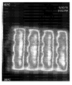
- FIG. 20 is a thermal image showing a state in which heat is generated when power is applied to FIG. 18.
- 21 is a flow chart of a control method of an energy delivery module for vaginal canal treatment according to another embodiment of the present invention.
- 22 is another flowchart of a control method of an energy delivery module for vaginal canal treatment according to another embodiment of the present invention.
- FIG. 23 is a flow chart of a vaginal canal treatment method using an energy delivery module for treating vaginal canal, which is another embodiment according to the present invention.
- FIG. 24 is a view showing a treatment area during vaginal canal treatment using the energy transfer module for vaginal canal treatment of FIG. 18.
- 25 is a plan view of an energy delivery module for treating vaginal canal according to another embodiment of the present invention.
- FIG. 26 is a partial cross-sectional view of a portion of FIG. 25 taken in cut.
- 27A, 27B, and 27C are views showing a modification of the arrangement of the RF electrode of FIG. 25.
- FIG. 28 is a flowchart of a control method of an energy delivery module for vaginal canal treatment according to another embodiment of the present invention.
- 29 is a flow chart of a control method of an energy delivery module for vaginal canal treatment according to another embodiment of the present invention.
- FIG. 30 is a flow chart of a vaginal canal treatment method using an energy delivery module for treating vaginal canal, which is another embodiment according to the present invention.
- FIG. 31 is a view showing a treatment area when treating vaginal canal using the energy transfer module for treating vaginal canal of FIG. 25.
- 32 is a plan view of an energy delivery module for treating vaginal canal according to another embodiment of the present invention.
- FIG. 33 is a partial cross-sectional view of a portion of FIG. 32 cut away.
- 34 is a flowchart of a control method of an energy delivery module for treating vaginal canal according to another embodiment of the present invention.
- 35 is a flowchart of a control method of an energy delivery module for treating vaginal canal according to another embodiment of the present invention.
- 36 is a flow chart of a vaginal canal treatment method using an energy delivery module for treating vaginal canal, which is another embodiment according to the present invention.
- FIG. 37 is a view showing a treatment area during vaginal canal treatment using the energy transfer module for vaginal canal treatment of FIG. 32.
- FIG. 38 is a graph showing a temperature profile for each part of electrode treatment using the energy transfer module for vaginal canal treatment of FIG. 32.
- tissue refers to a collection of cells distributed in the human vaginal canal
- the vaginal canal refers to a portion connecting the uterus and the vulva among female genital organs, and the inner wall or inner surface of the vaginal canal is inserted into the vaginal canal. It refers to the side where the treated device is in contact.
- tissue is explained on the premise that it refers to a part or all of the tissues distributed from the mucous membrane (mucosa) of the inner wall of the vaginal canal to a predetermined depth.
- treatment will be described on the premise that it refers to an act of performing tissue remodeling through thermal energy by transmitting RF energy to a submucosal vaginal tissue. For example, treatment for at least one of Tightening, Rejuvenation, laxity, lifting and Tone and Textural Changes on the inner wall of the vaginal canal.
- FIG. 1 is a block diagram showing the configuration of a first embodiment according to the present invention.
- the vaginal canal treatment apparatus may include a handpiece 10 and a body 20.
- the handpiece 10 is inserted into the vaginal canal and configured to transmit RF energy.
- the handpiece 10 may include an insertion portion 100 and a gripping portion 600 inserted into the vaginal canal.
- the insertion unit 100 is configured to be inserted into the vaginal canal and transmit RF energy while expanding the vaginal canal to treat tissue.
- the insertion unit 100 is configured to expand and contract by the user's input, and is configured to expand the vaginal canal during expansion. When the expansion part expands, the contact area with the inner wall of the vaginal canal increases to maximize the treatment area.
- the insertion portion 100 is configured to transmit energy in a state where the vaginal canal is expanded to treat tissue.
- it may be configured to include a temperature sensor 330 to measure the temperature during treatment.
- the gripping part 600 is configured to be gripped and used by a user, and supports the inserting part 100 so that the inserting part 100 can be inserted inside the vaginal canal in a gripped state.
- the gripping part 600 may be configured such that one side is connected to one end of the inserting part 100 and the other side can be transmitted from a fluid source and an energy source provided in the body 20.
- the gripping part 600 may be configured to include an input part so as to be delivered to the control part 22, and may be configured to include a display part to monitor the state of tissue and treatment state.
- the main body 20 is configured to supply energy and fluid necessary for treatment, and is configured to control the overall process in the treatment process.
- the main body 20 may include an RF generator 21, a fluid supply unit 23, and a control unit 22.
- the RF generator 21 is configured to receive energy from the outside and generate RF energy.
- the RF generator 21 generates RF energy used for treatment, and may be configured to generate RF energy of different frequencies according to a patient's constitution, tissue composition, and tissue size. For example, the energy used to treat the vaginal lining t can be adjusted in the range of 0.1 to 0.8 MHz.
- the fluid supply unit 23 is configured to expand the insertion unit 100 by supplying the fluid to the insertion unit 100.
- the fluid supply unit 23 may be configured to adjust the flow rate and pressure of the fluid to be supplied.
- the fluid supply portion 23 is configured to transfer an expansion medium in a liquid or gas state to the balloon.
- air in the atmosphere can be supplied, and a means for storing a separate expansion medium may be omitted.
- the fluid supply unit 23 may supply a fluid and may include a pump, a valve, and the like for maintaining pressure, but since such a configuration is widely used, a description of the configuration will be omitted.
- the control unit 22 is configured to perform overall control of the treatment device including the RF generator 21 and the fluid supply unit 23.
- the control unit 22 may be configured to treat the application time, power, voltage, current, energy amount, and frequency of RF energy generated by the RF generator 21. In addition, it may be configured to adjust the fluid supply amount and the supply pressure of the fluid supply unit 23.
- the control unit 22 may perform feedback control using the temperature of the tissue measured from the temperature sensor 330 when the RF generator 21 is controlled, and use a pressure sensor and a flow meter provided in the fluid supply unit 23 To perform fluid control.
- a treatment device using RF energy has been described as an example, but various types of energy capable of heating and treating tissue may be used.
- FIG. 2 is a perspective view of a first embodiment according to the present invention.
- the first embodiment according to the present invention may include a body 20 and a handpiece 10.
- the body 20 and the handpiece 10 are connected by a cable 30, and the cable 30 may include an RF cable, a fluid channel, and a feedback path.
- One side of the handpiece 10 may be configured to include a connector so that the cable 30 can be connected detachably.
- the on / off switch of the power source a frequency control lever capable of adjusting the frequency of the RF energy generated by the RF generator, and various information including the operation contents of the treatment device are displayed and the user A command may be input, and a touch screen for displaying treatment information may be installed.
- the control unit 22 may control the RF generation unit 21 and the fluid supply unit 23 according to a preset treatment mode, and if there is an input for changing a variable value of some of the treatment modes manually from the user, based on this It is configured to control the RF generator 21 and the fluid supply unit 23.
- FIG 3 is a perspective view of the handpiece 10
- Figure 4 is an exploded perspective view of the handpiece 10.
- the handpiece 10 is configured to include the insertion portion 100 and the gripping portion 600.
- the insertion portion 100 is configured to be inserted into the vaginal canal from the outside through the vaginal inlet as described above.
- the insertion portion 100 is configured to expand while being inserted into the vaginal canal to increase the diameter, and is configured to expand the vaginal canal while supporting the inner wall t of the vaginal canal as the diameter of the insertion portion 100 increases.
- the insertion unit 100 may include a shaft 110, a guide 500, a balloon 200, and an energy transmission unit 301.
- the shaft 110 may be configured such that one side is firmly connected to the gripping portion 600 so that the inserting portion 100 is firmly supported when inserted into the vaginal canal.
- the shaft 110 is configured to include a fluid channel to allow fluid to move inward.
- One side of the fluid channel is connected in fluid communication with the gripping portion 600, and the other side is formed with an outlet 111 so as to be in fluid communication with the balloon 200 outside the shaft 110.
- the length of the shaft 110 is configured to correspond to the length of the vaginal canal, and since the length of the vaginal canal may vary depending on individual differences, it may be composed of 2cm to 15cm.
- the diameter of the shaft 110 may be configured to 3cm or less to minimize the feeling of foreign body, pain or discomfort when inserted into the contracted vaginal canal.
- the guide 500 is provided on the gripping part 600 side of the shaft 110 and supports the end of the balloon 200 so as to prevent the balloon 200 from expanding in the outward direction of the vaginal canal when inflating. It is possible to prevent the expansion to the outside by transmitting the support force in the longitudinal direction.
- the balloon 200 is configured to expand and expand the vaginal canal and functions as an expansion unit.
- the balloon 200 is contracted to be inserted into the narrow vaginal canal when the insertion portion 100 is inserted inward, and when RF energy is transferred, the contact area between the inner wall t of the vaginal canal and the electrode 320 to be described later increases. It can be expanded to treat large areas.
- the average size of the female vaginal canal it is configured to be about 2 cm in diameter when contracted, and is configured to be about 5-10 cm in diameter when expanded, but is not limited thereto.
- the main direction of expansion of the balloon 200 may be expanded in a direction in which the diameter of the balloon 200 increases so that the area of the side surface increases.
- the female vaginal canal has one side connected to the cervix and the other side connected to the outside, so that the length change of the vaginal canal does not occur largely, and the main expansion direction is made in the direction in which the circumference becomes large.
- the vaginal canal is in the form of many wrinkles in the contracted state, and when the vaginal canal expands, the wrinkles gradually expand and the circumference increases and the diameter increases.
- wrinkles of the inner wall t of the vaginal canal gradually expand and an area in close contact with the outer surface of the balloon 200 increases.
- a negative pressure may be applied inside the balloon 200.
- the balloon 200 has a shaft 110 and a balloon 200 in a portion where the shaft 110 is inserted such that the shaft 110 is inserted into the gripping part 600 and the inside and outside of the balloon 200 is sealed. This can be attached. Meanwhile, the operation of the balloon 200 will be further described with reference to FIG. 6 later.
- the energy transmitting unit 301 is configured to contact the inner surface of the vaginal canal from the outer surface of the balloon 200 to transmit RF energy.
- the energy transfer unit 301 may include a base 310, an electrode 320, and a temperature sensor 330.
- the energy transfer unit 301 may be configured to have elasticity, and may be configured to be supported by the balloon 200 when inflated to change its shape, and to provide a restoring force when contracted. In addition, it can be configured to have elasticity to expand the balloon 200 and expand the vaginal canal to some extent in response to wrinkles or curves C of the inner wall t of the vaginal canal. However, this will be described in detail later with reference to FIGS. 7 and 8.
- the insertion unit 100 may further include a sheath 400 surrounding the shaft 110 and the balloon 200 so that the insertion into the vaginal canal is easily performed.
- the sheath 400 may be configured to have a cross-sectional shape of a C shape so that the user can pull it out and remove it from the outside so that it can be discharged to the outside by being separated from the insertion portion 100 in a state inserted into the vaginal canal.
- 5A to 5C are operation state diagrams of the handpiece 10.
- the insertion portion 100 of the handpiece 10 may be configured differently in the contracted first form and the expanded second form.
- the first form is a state in which compression is maximized by being in close contact with the shaft 110.
- the insertion part 100 enters in a compressed or contracted state so that insertion can be easily performed inside the vaginal canal.
- the balloon 200 is inflated as shown in FIG. 5B, the balloon 200 is expanded while the diameter of the insert 100 is increased.
- the expansion of the insertion portion 100 is gradually expanded by the energy transfer module that is curled as the balloon 200 expands, and the outer surface of the insertion portion 100 is continuously wrapped by the energy transfer module. Thereafter, when the balloon 200 is further expanded as shown in FIG.
- the diameter of the insertion portion 100 becomes maximum, and the contact area formed on the outer surface in the circumferential direction becomes maximum.
- the central portion of the insertion portion 100 becomes the first expansion portion 210 in a cylindrical shape, and at the end of the insertion direction, a second expansion portion 220 in a hemispherical shape is formed so that the main expansion direction has a wide diameter and a circumference. It expands in an increasing direction.
- 6A to 6C are operating state diagrams of the balloon 200.
- FIG. 6A shows the balloon 200 contracted
- FIG. 6B shows the balloon 200 expanded in the middle
- FIG. 6C shows the balloon 200 expanded to the maximum.
- the balloon 200 is configured to contract and expand, and the length L is maintained during expansion, and may be configured to expand while maintaining the overall shape.
- maintaining the length means that there is some length change, but the change is negligible when compared to the change in width.
- the balloon 200 exists in a somewhat wrinkled form in a contracted state, and may be a Semi-compliance balloon 200 configured to be expanded while maintaining the overall shape after being deformed into a certain shape.
- a compliance balloon 200 that continuously expands from the beginning such as a balloon and changes shape according to external force, it expands while maintaining an appropriate shape due to the energy transfer unit 301 provided on the outer surface during expansion. can do.
- the balloon 200 may include latex, and may include various stretchable materials suitable for medical use.
- FIG. 7 is an exploded view of the energy transmission unit 301, and FIG. 8 is a cross-sectional view of I-I 'of FIG. 7.
- the energy transmission unit 301 may include a base 310, an electrode 320, a temperature sensor 330, and a connection unit 340.
- the base 310 is provided with a space in which the electrode 320 is provided, and is configured such that the contact area of the electrode 320 may vary according to the expansion of the balloon 200.
- the base 310 is made of an elastic material or an elastic material and is configured to respond to the expansion of the balloon 200.
- the base 310 is, for example, configured to curl in the circumferential direction of the balloon 200, and as the balloon 200 expands, a portion that is curled may gradually expand and an outer surface may be enlarged.
- the electrode 320 is configured to be provided on the outer surface of the base 310.
- the base 310 When the base 310 is unfolded, it is generally formed in a quadrangular shape, and a plurality of electrodes 320 may be provided to allow the electrodes 320 to contact the inner wall of the vaginal canal at a plurality of points.
- the electrode 320 formed on the outer surface is also dried, so that the area in contact with the inner wall of the vaginal canal is changed.
- the base 310 is to cover the side of the balloon 200 except for the end side of the balloon 200 to prevent energy transfer to the portion of the genitals, which is in the longitudinal direction, for example, the cervix. Can be configured.
- a connection portion 340 is provided on one side of the base 310 so as to be electrically connected to the grip portion 600.
- the connection part 340 is relatively thin compared to the width of the base 310 and when a plurality of electrode 320 arrays are provided, an electric path for individually controlling each may be provided.
- the connection part 340 is flexibly connected when the shape of the base 310 changes according to the expansion of the balloon 200 and may be made of the same or similar elastic or stretchable material as the base 310 to prevent damage.
- the part where the connection part 340 and the base 310 are connected may be connected to a rounded part so as to prevent the shape of the base 310 from changing or when stress is concentrated when the insertion part 100 is taken out from the vaginal canal. Can be.
- the connecting portion 340 may be connected to the gripping portion 600 through the shaft 110.
- the base 310 may be provided with an attachment portion that is fixed to the balloon 200.
- the attachment portion is configured as a long region in the longitudinal direction to minimize the portion where the expansion is restricted by the attachment portion when the balloon 200 expands in the circumferential direction, and may further perform a function of limiting the expansion in the longitudinal direction.
- the attachment portion may be formed in the central portion of the electrode 320 so as to minimize resistance generated by frictional force in the overlapped portion of the base 310 when the balloon 200 is expanded. That is, half of the balloon 200 is clockwise thanks to the attachment portion, and the other half is wrapped around the balloon 200 counterclockwise. Therefore, since the amount of unwinding corresponding to the balloon 200 expansion becomes equal, frictional force can be significantly reduced compared to the case where all of them need to be unwound in one direction, and expansion can be smoothly achieved.
- the length of the base 310 may be determined such that when the balloon 200 is expanded to the maximum size inside the vaginal canal, at least a portion of the balloon 200 remains in an overlapped state. When it is removed from the inside of the vaginal canal after treatment is completed, it must be removed in a reduced state as in the case of insertion to prevent damage to the vaginal canal inner wall (t) and to prevent patient pain and discomfort. Therefore, even if the part of the base 310 overlaps even during the maximum expansion, the overlapped portion supports each other and can be returned to the dried state of the balloon 200 again. At this time, a restoring force providing unit (not shown) such as a leaf spring may be additionally provided for smooth return to the rolled original state. However, the base 310 may be deformed into a configuration in which the balloon 200 is spirally wound, and may be applied in various configurations surrounding the balloon 200.
- the electrode 320 is configured to transmit energy through the inner surface of the vaginal canal as described above.
- the electrode 320 may be provided in plural on a wide surface facing outward.
- the electrode 320 is of a bipolar type and may be repeatedly arranged.
- the electrodes 320 may be arranged in parallel in the circumferential direction so as to be in close contact with the inner wall of the vagina while maintaining a uniform electrode 320 distribution density even during expansion.
- the electrode 320 may be divided into a plurality of control regions divided in a plane on the base 310 to be connected to independent electrical paths so that they can be controlled independently for each region.
- the electrode 320 Since the electrode 320 is provided around the balloon 200 along the base 310 and is treated by applying energy to the inner wall of the vaginal canal at a predetermined depth, the tissue treatment area is formed in the rotational direction along the arrangement of the electrode 320. Also, it can be treated to a predetermined depth to generate an annular treatment area.
- the electrode 320 is described as a bipolar type, it may be configured as a monopolar type, and in this case, an electrode 320 pad in contact with the outside may be separately provided.
- the electrode 320 may be arranged to be divided into a plurality of regions along the periphery to prevent RF energy transfer in the overlapped portion between the energy transfer units 301, that is, the portion not contacting the tissue.
- the temperature sensor 330 may be configured to measure the temperature of the tissue. As the RF energy is transmitted, the temperature of the tissue changes, and it is configured to transmit the measured value to the control unit 22 by measuring it.
- the temperature sensor 330 may be configured in a plurality to be configured to measure the temperature of the tissue at a plurality of points. However, since the position of the temperature sensor 330 may be variously modified, a description thereof will be omitted, and the configuration may also be variously applied, so a description thereof will be omitted.
- the energy transmission unit 301 may be provided with an insulation unit in a plurality of regions as necessary.
- FIGS. 9A to 9C are use state diagrams of the first embodiment
- FIGS. 10A to 10C are views showing expansion of the insertion portion 100 and expansion of the lesion site.
- FIGS. 10A to 10C are views showing expansion of the insertion portion 100 and expansion of the lesion site.
- FIGS. 10A to 10C are views showing expansion of the insertion portion 100 and expansion of the lesion site.
- the insertion is inserted through the vaginal canal inlet with the insertion portion 100 is contracted.
- a lubricant may be applied to the outer surface of the energy transmission unit 301 for smooth insertion.
- the user inserts the insertion part 100 in the longitudinal direction from the entrance of the vaginal canal while holding the gripping part 600 of the handpiece 10.
- the insertion depth of the insertion unit 100 may be different for each individual.
- the insertion portion 100 may be inserted to a depth where the end of the insertion portion 100 is adjacent to or close to the cervix.
- the control unit 22 operates the fluid supply unit 23 to supply fluid to the balloon 200.
- the balloon 200 expands, and accordingly, the electrode 320 module is released, and the inner wall of the vaginal canal is expanded.
- the control unit 22 may supply the fluid at a pressure higher than the body pressure.
- the balloon 200 When the insertion portion 100 expands and the inner wall t of the vaginal canal expands, body pressure and elasticity of the inner wall t of the vaginal canal itself, elasticity of the balloon 200, and resilience of the energy transfer unit 301 occur, thereby causing the balloon ( 200) When the pressure inside is higher than the body pressure, the balloon 200 can be expanded. After the balloon 200 is inflated, the amount of expansion may be maintained by maintaining the pressure acting on the balloon 200.
- the controller 22 is configured to transmit RF energy while the balloon 200 is inflated.
- the energy transfer unit 301 is in a loose state and is in contact with the inner surface of the vaginal canal in a large area to transmit RF energy.
- the balloon 200 is contracted and the insertion portion 100 is taken out of the vaginal canal.
- FIG. 10 changes in the cross-sectional shape of the insertion portion 100 and the vaginal canal are illustrated corresponding to FIGS. 9A to 9C.
- FIG. 10A in the insertion step, there are significant wrinkles on the inner wall of the vaginal canal, and a portion that does not contact the outer surface of the electrode 320 is scattered.
- the energy transfer unit 301 is released, and the vaginal canal is also expanded. As the energy transfer unit 301 is released, the contact area between the inner wall t of the vaginal canal and the electrode 320 is gradually increased.
- the balloon 200 expands, the energy transfer unit 301 is released, and the vaginal canal expands, and most of the inner wall t of the vaginal canal comes into contact with the electrode 320 module. Thereafter, RF energy is transmitted while maintaining the expanded state.
- each pair of the energy transfer unit 301 locally transmits energy to heat the tissue, and as a whole is disposed in plurality along the circumference of the energy transfer unit 301, the treatment area may be formed in an annulus for one treatment.
- the energy transmission unit 301 may be configured in an arrangement composed of a plurality of rows and columns in the longitudinal and circumferential directions.
- the plurality of electrodes 320 are configured to independently control whether RF energy is transmitted for each unit region (dashed line).
- the arrangement of the plurality of electrodes 320 may perform energy blocking for the uninserted portion 100 when the insertion depth is different according to individual differences for each region, and the portion in which the energy transfer unit 301 is superimposed, that is, tissue It is possible to block the energy transfer to the electrode 320 which is not in contact with.
- the electrode 320 may be configured by printing on the outer surface of the balloon 200.
- the balloon 200 may be formed by printing the electrode 320 on the outer surface of the balloon 200 in an expanded state, and each pair of electrodes 320 may be configured to be individually controlled. In addition, it is printed in a contracted state and may be configured to allow the electrode 320 to be stretched according to the expansion of the balloon 200.
- the electrode 320 may be formed by printing a conductive material directly on the outer surface of the balloon 200 or by printing on a buffer provided on the outer surface of the balloon 200.
- the electrode 320 is formed and printed in the longitudinal direction on the balloon 200, this is only an example, and may be printed in the circumferential direction or may be formed in a spot type at a plurality of points.
- the energy transmission unit 301 is composed of a plurality of individual modules may be attached at a predetermined angle to the outer surface of the balloon 200, respectively.
- the shape can be smoothly changed in response to the curvature (C) of the inner surface of the vaginal canal, and the distribution density of the electrode 320 per unit area can be changed according to the expansion, so that the treatment area can be adjusted accordingly.
- the second embodiment may be configured to include the same components as the first embodiment.
- the description will be omitted to avoid overlapping description, and only the configuration having a difference will be described.
- 13A and 13B are use state diagrams of the second embodiment.
- the thickness of the insert 100 in the contracted state is configured to be thicker than in the first embodiment.
- the thickness of the shaft 110 is configured to be thick, and is configured to greatly expand the vaginal canal when inserted into the vaginal canal. Thereafter, the maximum value of the expansion of the insertion portion 100 may be configured in the same manner as in the first embodiment (FIG. 13B).
- the vaginal canal can be expanded at the same time as the insertion (FIG. 13A), and since the balloon 200 is subsequently expanded, the minimum amount of expansion of the vaginal canal inner wall (t) is guaranteed. It can be, the minimum expansion shape is also expanded to correspond to the shape of the insertion portion 100 to ensure this.
- FIG. 14 is a flowchart of a method of controlling a vaginal canal treatment device according to an embodiment of the present invention.
- control method of the vaginal canal treatment apparatus may be configured to include an expansion step (S100), a step of applying energy (S200) and a contraction step (S300).
- the expanding step (S100) corresponds to the step of expanding the treatment device inserted into the vaginal canal within a predetermined range.
- the area where the corrugated vaginal inner wall (t) contacts the treatment device is increased.
- the expansion of the treatment device may expand the expansion unit provided in the treatment device.
- the treatment device gradually expands the expansion unit and expands to a predetermined range.
- the amount of expansion can be expanded to a predetermined range, it can also be configured to be adjustable according to the user's input.
- the step of applying energy (S200) is a step of supplying energy to the energy transmission device provided in the expansion unit. At this time, the energy transferred by sensing the contact area and insertion depth of the expansion portion and the inner wall t of the vaginal canal can be adjusted.
- feedback control may be performed by measuring the temperature of the tissue to which the energy is transferred. The tissue to which the energy has been transferred is heated to denature the tissue and treatment may be performed.
- the energy may be various types of energy, such as RF energy, laser, light, and ultrasound.
- the contraction step (S300) corresponds to the step of contracting the expansion part as a pre-step before applying the energy to the tissue and then pulling the expansion part out of the vaginal canal.
- the expansion can be contracted to a minimum to facilitate ease when removed from the vaginal canal.
- FIG. 15 is a flow chart of a control method of a vaginal canal treatment device according to another embodiment of the present invention.
- the expansion step (S100) may include a fluid injection step (S110) and a pressure maintenance step (S200).
- the step of applying energy (S200) may include a contact portion determining step (S210), an electrode selection step (S220), and applying RF energy (S230).
- the contraction step (S300) may include a fluid recovery step (S310) and a pressure maintaining step (S320).
- the fluid injection step (S110) corresponds to the step of injecting fluid into the balloon inserted into the vaginal canal to inflate the balloon provided in the expansion unit.
- Flow rate adjustment and hydraulic pressure adjustment may be selectively performed according to the amount of expansion when the fluid is injected.
- Fluid injection may be performed by adjusting the flow rate supplied from the fluid supply unit.
- the pressure maintaining step (S120) corresponds to a step of maintaining the amount of expansion so that the inner wall t of the vaginal canal which is in contact is fixed when the balloon is expanded to an appropriate range. At this time, it is configured to maintain the pressure, and the fluid line connected to the balloon can be sealed to maintain the pressure. In addition, it can be configured to provide a uniform pressure through the servo control.
- the contact portion determining step S210 corresponds to a step of determining the electrode in contact with the inner wall and the quality of the electrodes provided in the expansion portion. There are individual differences in the structure and size of the vaginal canal. The contact portion and the non-contact portion that are individually changed according to individual differences are determined.
- the electrode selection step (S220) corresponds to the step of excluding the non-contact electrode from the energy application target electrode so as to prevent application of energy to the electrode when energy is applied.
- the step of applying RF energy corresponds to the step of applying the RF energy through the selected contact electrode to transfer energy to the tissue. As RF energy is transmitted, treatment inside the vaginal canal may be achieved.
- control may be performed by reflecting the electrical characteristics of the tissues that are individually generated according to a predetermined program.
- the fluid recovery step (S310) corresponds to the step of recovering the fluid so that the balloon can contract after the application of the RF energy is finished.
- the fluid existing in the balloon may be discharged to the outside by generating a negative pressure in the fluid supply unit 23 to recover the fluid.
- the balloon may shrink due to the pressure of the vaginal canal itself.
- the pressure maintaining step (S320) corresponds to a step of generating and maintaining a negative pressure in the balloon so as to prevent the balloon that has been contracted by the elasticity of the balloon itself from expanding somewhat. The user is able to remove the inflation portion outside the vaginal canal while the balloon is contracted by maintaining the negative pressure.
- negative pressure is exemplified, but it can be contracted by providing various ranges of pressure that can cause the balloon to contract inside the vaginal canal.
- the vaginal canal treatment method may include a step of expanding the vaginal canal by inserting a treatment device (S1000), a tissue treatment step (S2000), and a step of removing the treatment device (S3000).
- the step of expanding the vaginal canal by inserting a treatment device (S1000) corresponds to the step of expanding the vaginal canal to a predetermined range by inserting a treatment device formed with a predetermined thickness from the entrance of the vulva side of the vaginal canal. When inserted, it is possible to secure the expansion of the vaginal canal by inserting with a certain thickness.
- the tissue treatment step (S2000) corresponds to the step of treating the tissue by transmitting energy to the vaginal canal inner wall (t) side with the vaginal canal extended.
- the treatment of the tissue transfers energy to heat the tissue and causes degeneration, and the tissue can be remodeled through a certain recovery period in the future.
- the step of removing the treatment device (S3000) corresponds to the step of removing the treatment device from the vaginal canal.
- the treatment device is contracted and removed.
- the sheath 400 may be used to wrap the treatment device and then remove it together.
- FIG. 17 is a flow chart of another embodiment vaginal canal treatment method according to the present invention.
- the same configuration as the above-described treatment method may be applied, and the description thereof will be omitted and only the configuration having a difference will be described.
- treatment is performed by expanding the vaginal canal.
- the step of inserting the treatment device into the vaginal canal corresponds to the step of inserting the treatment device through the vaginal entrance at the vulva side of the female genitalia.
- the treatment device may be inserted in a contracted state with a minimized diameter.
- the position of the energy transmission unit 301 may be adjusted for treatment of the inner wall of the vaginal canal.
- the insertion can be completed by removing only the sheath 400 after positioning using the sheath 400 surrounding the treatment device.
- the step of expanding the vaginal canal corresponds to the step of expanding the vaginal canal by expanding the expanded portion of the inserted treatment device.
- the expansion of the vaginal canal is mainly expanded in the circumferential direction, and as the vaginal canal is expanded, the area where the energy transfer module of the treatment device and the inner wall of the vaginal canal contact can be widened.
- the shape to be expanded as a whole may be expanded in a cylindrical shape.
- the treatment area may be a side portion of the vaginal canal expanded in a cylindrical shape.
- FIG. 18 is a plan view of an energy delivery module 300 for a vaginal canal treatment device according to another embodiment of the present invention
- FIG. 19 is a partial cross-sectional view of a portion of FIG.
- the energy transmission module 300 for vaginal vascular treatment is provided with a flexible substrate and a plurality of heating electrodes 321 provided on the substrate to be configured to heat the treatment area.
- the energy transfer module 300 is disposed on the outer surface of the expansion portion and is configured to heat the inner wall of the vaginal canal.
- the energy transfer module 300 is an energy transfer unit 301 inserted into the vaginal canal, a connector 360 configured to be electrically connected to the outside, and an energy transfer unit 301 and a connector 360 to be connected. It may be configured to include an extended portion 340 is configured.
- the insertion portion is formed in the form of a square plate as a whole, and one side is a support surface supported by contact with the above-described expansion portion, and the other side is configured to contact the inner wall of the external vaginal canal.
- the energy transmission unit 301 may be configured to be inserted into the vaginal canal together with the expansion unit 200 while being dried in a cylindrical shape, and supported and expanded by the expansion of the expansion unit 200. In addition, when the expansion portion is contracted, the energy transfer unit 301 may be configured to contract due to its own restoring force of the inner wall of the vaginal canal.
- the energy transmission unit 301 may be made of an elastic and deformable material as a whole.
- the energy transfer unit 301 includes a base 310, a first layer 311, a second layer 312, a heating electrode 321, a temperature sensor 330, an extension 340, an extension 350, and It may be configured to include a connector (360).
- the base 310 is made of an insulating material, is made of an elastic material, and may be a base on which the remaining components are disposed.
- the first layer 311 is configured to electrically insulate the heating electrode 321 to be described later and the temperature sensor 330.
- the second layer 312 is configured to insulate the heating electrode 321 from the outside. It functions as the outermost layer in the energy transfer module 300, and when it is inserted into the vaginal canal, it directly contacts the inner wall of the vaginal canal.
- the second layer 312 may be formed of a material having an electrically insulating function.
- the second layer 312 may be formed of a material having high thermal conductivity so as to increase the efficiency of receiving heat energy from the heating electrode 321 to be described later and transferring it to the inner wall of the external vaginal canal.
- the heating electrode 321 is configured to generate heat by receiving electric energy.
- the heating electrode 321 may be configured as a planar heating electrode 321 to heat a large area.
- the flexible substrate is composed of a plurality of regions so that each of the individual regions defined by being divided into a plurality of plane regions can be independently heated. As an example, as shown in FIG. 1, it may be an individual area divided into a 4 x 4 array. However, the individual areas may be divided into various numbers only as an example.
- the heating electrode 321 is formed in a shape extending in a predetermined width, and may be disposed in a shape that progresses while reciprocating both sides in one individual region. Therefore, electrodes are disposed parallel to each other inside one individual region, and the current direction may be reversed between the closest electrodes. Therefore, when an electric current is applied, inductive heating is generated so that heat is generated at a portion of each electrode. At this time, the current may be generated by applying an AC electrode or a pulse wave current.
- the heating electrode 321 is formed on the first layer 311 and may be configured to be insulated from the outside and the second layer 312.
- the heating electrode 321 is not directly in contact with the outside, that is, the inner wall of the vaginal canal, and the generated thermal energy is transferred to the inner wall of the vaginal canal through the second layer 312.
- the heating electrode 321 may be formed to a suitable thickness so that deformation can be smoothly performed when the substrate is deformed according to expansion of the expansion portion.
- the temperature sensor 330 is configured to measure the temperature of the energy transfer module 300 or the inner wall of the vaginal canal as the temperature of the heating electrode 321 increases.
- the temperature sensors 330 may be provided in a plurality of individual regions, respectively, and may be provided in a plurality of individual regions.
- the temperature sensor 330 is distinguished from the layer on which the heating electrode 321 is disposed, and may be provided between the base 310 and the first layer 311.
- the configuration in which the temperature sensor 330 is disposed is an example, and may be provided at various positions capable of measuring temperature without affecting the electrodes.
- the temperature sensor 330 may be provided with the heating electrode 321 between the first layer 311 and the base 310.
- the second layer 312 may be omitted according to the arrangement of the temperature sensor 330.
- the temperature sensor 330 may be configured to be exposed to the outside and directly contact the inner wall of the vaginal canal.
- a plurality of electrical paths connected to each of the heating electrodes 321 and the temperature sensor 330 may be configured.
- the connector 360 is configured to be electrically connected to the handpiece.
- the connector 360 may be configured to be substantially not inserted into the vaginal canal.
- the extension part 340 is configured to connect the energy transmission part 301 and the connector.
- the extension part 340 is formed to extend from one side of the energy transmission part 301, and the base 310, the first layer 311 and the second layer 312 of the energy transmission part 301 are formed to extend. Can be.
- An electrical path formed by extending from the energy transmission unit 301 is disposed in the extension unit 340 and may be connected to a connector.
- the extension portion 340 may be formed to have a narrower width than the energy transfer portion 301 so that large deformation does not occur even when the expansion portion expands.
- the extension 340 may be configured to be substantially not inserted into the vaginal canal.
- the extension portion 350 may be formed to extend in a width direction at a portion where stress is concentrated on a connection portion between the energy transfer portion 301 and the extension portion 340. When the expansion portion expands, the expansion portion 350 is configured to deform the energy transfer portion 301 and disperse the stress at the boundary portion where the deformation and stress are concentrated.
- the extension part 350 may be formed by extending the base 310, the first layer 311 and the second layer 312, and gradually widen from the extension part 340 to the energy transmission part 301 side.
- the paper may be configured in a shape.
- FIG. 20 is a thermal image showing a state in which heat is generated when power is applied to FIG. 18.
- the heating electrode 321 when power is applied to the heating electrode 321, it is configured to generate heat by itself even if it is not in contact with an external medium.
- the divided regions are divided to generate heat, and although not shown, each region may be individually configured to generate heat from power control of the controller.
- 21 is a flow chart of a control method of an energy delivery module for vaginal canal treatment according to another embodiment of the present invention.
- control method of the energy transfer module for treating vaginal canal equipped with a heating electrode is a step of applying electric power as first power to the planar heating electrode (S4010), so that the inner wall of the vaginal canal is maintained for a set temperature and a set time. It may be configured to include the step of applying power to the power (S4020).
- the step of applying electric power with the first power to the planar heating electrode (S4010) corresponds to the step of applying AC to the heating electrode 321 so that the energy transfer module 300 shown in FIG. 18 can be heated.
- the temperature measurement value measured from the temperature sensor 330 may be fed back to the set temperature.
- the temperature sensor 330 measures the temperature of the inner wall of the vaginal canal or the temperature of the energy transmission unit 301 itself according to the placed position, so the set temperature may vary depending on the installed position.
- the set temperature may be set at 60 ° C. on the inner wall of the vaginal canal or at 60 ° C. in the energy transfer unit 301.
- the step of applying electric power with the second power so that the inner wall of the vaginal canal is maintained for a set temperature and a set time (S4020) has power of a size capable of maintaining 40 to 60 ° C without the temperature of the inner wall of the vaginal canal exceeding 60 ° C. Can be.
- the set time can be several seconds to several minutes. Therefore, coagulation denaturation may occur in the inner wall of the vaginal canal in contact with the energy transfer unit 301.
- 22 is another flowchart of a control method of an energy delivery module for vaginal canal treatment according to another embodiment of the present invention.
- the present control method is configured such that heating is individually performed on a plurality of divided regions. For example, when the energy transmission unit 301 of FIG. 18 is not fully unfolded and some areas overlap or there is a part that is not inserted inside the vaginal canal, the area in contact with the inner wall of the vaginal canal is selectively heated. It is configured to be.
- the contact area determination step (S4110), the first power application step (S4120) to the heating electrode in the contact area, the temperature determination step (S4130), the PWM control step (S4140), and the setting time elapsed determination step It may be configured to include (S4150).
- the contact area determining step S4110 may be configured to determine whether or not the inner wall of the vaginal canal is in contact when the expansion unit is expanded and the energy transfer unit 301 is unfolded.
- the contact area determination step (S4120) when the energy transmission unit 301 is inserted into the vaginal canal, the temperature is measured at a plurality of points to check whether there is contact.
- the contact area may be formed in units of a cleavage area where each heating electrode 321 is independently controllable.
- the portion in contact with the inner wall of the vaginal canal in the state where the energy transfer unit 301 is unfolded rises at a similar rate from room temperature to body temperature.
- the energy transmission unit 301 since the energy transmission unit 301 is not expanded, some overlapping portions do not directly contact the inner wall of the vaginal canal, so the rate of rise is somewhat slower, and thus a difference in temperature measurement occurs.
- the portion not inserted in the longitudinal direction is maintained at room temperature, it is possible to determine whether or not it is in contact.
- the power is applied to the individual regions determined as the contact regions described above. For example, AC power is applied to control the heating electrode 321 to generate heat.
- the step of determining the temperature of the contact area corresponds to a step of continuously measuring the temperature of the contact area to determine whether the temperature has risen to a set temperature.
- the set temperature may be 60 ° C.
- the PWM control step (S4140) corresponds to the step of controlling the power to be continuously maintained at a set temperature for a predetermined time after being heated to the set temperature.
- Pulse width modulation (PWM) control is performed on the heating electrodes 321 disposed in the individual regions in contact to control the amount of heat generated.
- PWM pulse width modulation
- the amount of heat generated may be controlled by adjusting the voltage.
- the determination step (S4150) of whether or not the set time has elapsed is configured to determine whether the target treatment is maintained at a treatment temperature for a predetermined time.
- the above-described PWM control can be achieved until the set time elapses.
- FIG. 23 is a flow chart of a vaginal canal treatment method using an energy delivery module 300 for treating vaginal canal, which is another embodiment according to the present invention.
- expanding the vaginal canal (S4210), heating the vaginal canal (S4220), maintaining the inner wall of the vaginal canal for a predetermined time (S4230), and shrinking the vaginal canal and removing the treatment device It may be configured to include (S4240).
- the step of expanding the vaginal canal corresponds to the step of inserting the insertion portion of the treatment device equipped with the heating electrode 321 shown in FIG. 18 into the entrance of the vaginal canal, and expanding the inner portion of the vaginal canal by expanding the expansion portion.
- the expansion unit may be performed by injecting a fluid using a manual pump or an automatic pump as described above.
- the step of heating the vaginal canal corresponds to the step of heating the side surface of the vaginal canal using the heating electrode 321 using the planar heating electrode 321. Heating will heat the inner wall of the vaginal canal to 40 ° C to 60 ° C.
- the step of maintaining the inner wall of the vaginal canal for a predetermined time corresponds to the step of maintaining the inner wall of the vaginal canal at 40 ° C to 60 ° C for a predetermined time so as to achieve a therapeutic purpose.
- the inner wall of the vaginal canal is maintained at 40 ° C to 60 ° C for a predetermined time so that tissue degeneration occurs by heating and coagulation can occur.
- the step of contracting the vaginal canal and removing the treatment device is a step of contracting the treatment device so that the vaginal canal returns to its original diameter and shape after transferring heat energy inside the vaginal canal, and then pulling it out of the vaginal canal. It corresponds.
- FIG. 24 is a view showing a treatment area during vaginal canal treatment using the energy transfer module for vaginal canal treatment of FIG. 18.
- the energy transfer unit 301 contacts the inner wall of the vaginal canal to transfer thermal energy, and at this time, the thermal energy is transferred using the planar heating electrode 321 to contact the side surface. Tissue degeneration in the area can be treated.
- an energy delivery module for treating vaginal canal which is another embodiment according to the present invention, a control method and a method of treating vaginal canal using the same will be described in detail with reference to FIGS. 24 to 31.
- the same components as the above-described embodiments may also be included, and in order to avoid overlapping descriptions of the same components, the different components will be described in detail.
- FIG. 25 is a plan view of another embodiment of a vaginal canal treatment energy transfer module 300 according to the present invention
- FIG. 26 is a partial cross-sectional view of a portion of FIG. 25
- FIG. 27 is a modification of the arrangement of the RF electrode of FIG. It is a figure showing an example.
- the RF electrode 322 may be included.
- the RF electrodes 322 may be configured and arranged in a plurality of individual regions.
- the RF electrode 322 may be formed to be spaced apart from the adjacent RF electrode 322 by a predetermined distance so that spot heating can be performed.
- a plurality of RF electrodes 322 may be configured to be exposed toward the second layer 312.
- the RF electrode 322 is configured to receive RF power from the control unit and transmit it to the tissue, and may be configured to generate heat by the impedance of the tissue. Therefore, it is exposed to the second layer 312 side so that RF energy can be transmitted to the tissue, and preferably the RF electrode 322 may be exposed than the second layer 312.
- the RF electrode 322 may be configured in a smooth shape or a flat surface so that the contact surface can transmit RF energy in a non-invasive manner upon contact with the inner wall of the vaginal canal.
- the energy transfer unit 301 In the state inserted inside the vaginal canal, the energy transfer unit 301 is unfolded according to the expansion of the expander, and this is to prevent damage to the inner wall of the vaginal canal that is in contact with it.
- each RF electrode 322 is illustrated in an example of a flat cylindrical shape, this is only an example and may be configured in various configurations.
- the RF electrode 322 may be configured as a bipolar type. In addition, it may be of a monopolar type as shown in Figure 27c.
- the RF electrode 322 may be configured to have opposite polarities. Specifically, any one column may be configured to have the same polarity, or even one column may be configured to cross polarities.
- the arranged electrodes may be configured to have the same polarity.
- a separate ground plate (not shown) may be in contact with the body outside the vaginal canal. In this case, RF energy is transferred from each RF electrode 322 to the inner wall of the vaginal canal.
- the electrical path according to the arrangement of the RF electrode 322 may be configured.
- an electrical path may be configured to enable independent control for each area.
- FIG. 28 is a flowchart of a control method of an energy delivery module 300 for vaginal canal treatment according to another embodiment of the present invention.
- the present embodiment may be configured to include an RF energy application step (S5010), a determination whether the set temperature is reached (S5020), and an RF energy blocking step (S5030).
- S5010 an RF energy application step
- S5020 a determination whether the set temperature is reached
- S5030 an RF energy blocking step
- the RF energy application step (S5010) corresponds to the step of applying RF energy to the RF electrode 322 that is in contact with the vaginal canal in an expanded state after being inserted into the vaginal canal.
- the application of RF energy may be performed by a control unit of the main body.
- the determination step S5020 of whether to reach the set temperature is a step of determining whether the temperature of the treatment area has reached the treatment temperature. Whether to reach the set temperature is configured to determine whether the temperature of the inner wall of the vaginal canal reaches a set temperature selected within a range of 60 ° C to 100 ° C. Whether to reach the set temperature can experimentally derive the time at which the temperature of the mucous membrane is heated to the set temperature according to the RF power. In this case, it is determined that the set temperature is reached when RF energy is applied for a predetermined time with the set RF power. You can. At this time, a predetermined time for which RF energy is applied may be several ms to several seconds.
- whether or not the set temperature is reached can be determined by estimating the tissue temperature according to the impedance value of the tissue measured from the RF electrode 322 and the amount of change in the impedance value. In addition, it is possible to determine whether or not the set temperature is reached according to the measured value using the temperature sensor 330 provided in the energy transfer unit 301.
- the RF energy blocking step (S5030) corresponds to a step of blocking the RF energy when it is determined that the tissue has reached a set temperature so as to prevent excessive damage to the excessive tissue.
- 29 is a flow chart of a control method of an energy delivery module for vaginal canal treatment according to another embodiment of the present invention.
- the RF energy application area selection step (S5110) the step of applying RF energy to the RF electrode 322 disposed in the selected RF energy application area (S5120), determining whether the set temperature is reached ( S5130) and the RF energy blocking step (S5140).
- the RF energy application region selection step S5110 corresponds to a step of determining a region to which RF energy is applied among a plurality of individual regions.
- the RF energy application region may be selected by measuring the impedance value using the RF electrode 322 to determine whether or not contact with tissue is performed.
- the temperature sensor 330 may be used to determine whether the temperature rises or not to determine whether or not contact is made.
- the step of applying RF energy to the RF electrodes disposed in the selected RF energy application region corresponds to the step of independently applying RF energy to the plurality of RF electrodes 322 disposed in the selected individual region.
- FIG. 30 is a flowchart of a vaginal canal treatment method using an energy delivery module 300 for treating vaginal canal, which is another embodiment according to the present invention.
- the step of expanding the vaginal canal (S5210), heating a plurality of spaced apart points with an RF electrode to treat tissue (S5220), and shrinking the vaginal canal and removing the treatment device (S5230) may be configured to include.
- step of expanding the vaginal canal (S5210) and the step of contracting the vaginal canal and removing the treatment device (S5230) can be performed in the same manner as described with reference to FIG. 23 (S4210, S4240), so a detailed description thereof will be omitted.
- the step of treating tissue by heating a plurality of spaced apart points with an RF electrode corresponds to a step of heating the inner wall of the vaginal canal by applying RF energy to the plurality of RF electrodes 322.
- This step is performed using a plurality of RF electrodes 322 contacting the inner wall of the vaginal canal, and treatment is performed at a plurality of spots in contact with the RF electrodes 322.
- the treatment applies RF energy so that the temperature of the tissue can be raised within the range of 60 ° C to 100 ° C.
- the inner wall of the vaginal canal rises from 60 ° C to 100 ° C so that cells in the tissue undergo coagulation and denature into ablation to perform treatment.
- RF energy may be applied for several ms to several seconds to transfer the RF energy and transform it into an ablation state.
- the RF electrode 322 may be performed as either a bipolar or monopolar type.
- FIG. 31 is a view showing a treatment area when treating vaginal canal using the energy transfer module for treating vaginal canal of FIG. 25. As illustrated, RF energy is applied to a plurality of points R to generate ablation degeneration at a plurality of points on the inner wall of the vaginal canal.
- an energy delivery module for treating vaginal canal which is another embodiment of the present invention, a control method thereof, and a method of treating vaginal canal using the same will be described in detail with reference to FIGS. 32 to 38.
- the same components as the above-described embodiments may also be included, and in order to avoid overlapping descriptions of the same components, the different components will be described in detail.
- FIG. 32 is a plan view of an energy delivery module for treating vaginal ducts according to another embodiment of the present invention
- FIG. 33 is a partial cross-sectional view of a portion of FIG.
- FIG. 32 in the present embodiment, a state in which the heating electrode 321 and the RF electrode 322 are provided so that planar heating and spot heating can be performed in a plurality of divided individual regions is illustrated. have.
- the heating electrode 321 and the RF electrode 322 may be configured to be overlapped so that spot heating is performed on a portion of the area where the plane heating is performed. In this case, when energy is applied to both the heating electrode 321 and the RF electrode 322, coagulation denaturation may occur entirely on the inner wall of the vaginal canal contacting one individual region, and ablation denaturation may occur at a plurality of spots. .
- the heating electrode 321 and the RF electrode 322 are provided together, and a third layer 313 may be additionally provided.
- the heating electrode 321 is blocked from the outside by the second layer 312 and the third layer 313 so that only heat energy is transmitted to the outside through self heating.
- the RF electrode 322 is provided on the upper surface of the third layer 313 to directly contact the inner wall of the vaginal canal and transmit RF energy.
- a third layer 313 is provided to insulate between each RF electrode 322.
- FIG. 33 shows an embodiment in which the heating area, which is the unit of arrangement of the heating electrode 321, and the RF energy applying area, which is the unit of placement of the RF electrode 322, overlap, the area where the heating area and the RF energy application area overlap.
- the regions are divided, and the heating electrode 321 and the RF electrode 322 may be arranged.
- 34 is a flowchart of a control method of an energy delivery module for treating vaginal canal according to another embodiment of the present invention.
- the step of applying power to the planar heating electrode (S6010), controlling the power applied to the planar heating electrode (S6020), and applying RF energy to the RF electrode (S6030) may be configured. have.
- the step of applying power to the heating electrode corresponds to the step of applying power to the heating electrode 321 to generate heat in the heating electrode 321.
- AC power is applied to transfer heat energy to the tissue contacting the energy transfer unit 301.
- the step of controlling the electric power applied to the planar heating electrode (S6020) corresponds to the step of heating to a set temperature to maintain coagulation denaturation on the inner wall of the vaginal canal contacting the energy transfer unit 301 and maintaining it for a set time.
- the set temperature is set in a range of 40 ° C to 60 ° C where coagulation of tissues can occur, and AC power can be set so as not to exceed 60 ° C.
- the set temperature may be maintained by controlling the AC power by feeding back the measured value from the temperature sensor 330 provided in the energy transfer module 300. For example, PWM control or voltage control may be performed.
- the step of applying RF energy to the RF electrode corresponds to the step of applying RF energy to the plurality of RF electrodes 322.
- the step of applying RF energy to the RF electrode 322 is performed to cause ablation of tissue in a plurality of spot regions.
- the power of RF energy can be controlled so that treatment can be performed within a range in which the tissue temperature does not exceed 100 ° C.
- 35 is a flowchart of a control method of an energy delivery module for treating vaginal canal according to another embodiment of the present invention.
- planar heating region selection step S6110 and the RF energy application region selection step S6120 may be further included.
- the planar heating region selection step S6110 corresponds to the step of selecting a region to which energy is applied among the planar heating electrodes 321. This step may be set by a user's input, and may be selected for a region determined to have contacted the inner wall of the vaginal canal among a plurality of planar heating regions.
- the RF energy application area selection step (S6120) corresponds to a step of selecting an area to which RF energy is applied among a plurality of RF energy application areas, and similar to the planar heating area selection step (S6110), the user's selection or the algorithm included in the control section It can be configured to be selected by.
- planar heating region and the RF energy application region may be selected independently of each other, may be selected differently from each other, and may also be selected identically.
- the step of applying power to the planar heating electrode (S6130) is performed first and the step of applying RF energy to the RF electrode (S6140) is described later, but the two steps are reversed. It can be performed, or can be controlled to be performed simultaneously.
- FIG. 36 is a flow chart of a vaginal canal treatment method using an energy delivery module 300 for treating vaginal canal, which is another embodiment according to the present invention.
- the step of expanding the vaginal canal (S6210) and the step of contracting the vaginal canal and removing the treatment device (S6250) can be performed in the same manner as described with reference to FIG. 23 (S4210, S4240), so detailed description is omitted Do it.
- the vaginal canal inner wall is 40 ° A step of maintaining a predetermined time at C to 60 ° C (S6230) and a tissue treatment step of heating the inner wall of the vaginal canal to 60 ° C to 100 ° C by transmitting RF energy to RF electrodes contacting the inner wall of the vaginal canal at a plurality of spaced points. It may be configured to include (S6240).
- the step (S6220) of heating the inner wall of the vaginal canal extended with the planar heating electrode to 40 ° C to 60 ° C and the step of maintaining the inner wall of the vaginal canal at 40 ° C to 60 ° C for a predetermined time (S6230) are the steps described in FIG. 23 ( S4220, S4230).
- FIG. 37 is a diagram illustrating a treatment area during vaginal canal treatment using the energy transfer module 300 for vaginal canal treatment of FIG. 32.
- coagulation degeneration can be generated in most areas, and ablation degeneration can occur at a plurality of spots overlapped therewith to cause different degeneration for each part. It is configured to be.
- FIG. 38 is a graph showing the temperature profile of each part during electrode treatment using the energy delivery module 300 for treating vaginal canal of FIG. 32. 38 shows a portion of the inner wall of the vaginal canal that is in contact with the energy transfer module 300 and the energy transfer module 300.
- an example in which a coagulation region and an ablation region are overlapped is generated.
- the temperature is maintained for a predetermined time.
- Treatment by planar heating is relatively time-consuming than the transfer of RF energy because the heating is performed by heat transfer due to a temperature difference between the inner wall of the vaginal canal and the heating electrode 321. Therefore, first, it is maintained at 60 ° C. for a predetermined time so that coagulation denaturation occurs in the tissue by planar heating. Thereafter, RF energy is transferred to a portion T2 of the RF electrode 322 and heated to 100 ° C. for a short time to generate ablation.
- the coagulation degeneration region and the ablation degeneration region may be treated by being partially overlapped or selected as non-overlapping regions.
- ablation degeneration occurs first, but ablation degeneration may occur during coagulation degeneration.
- the energy delivery module for the vaginal canal treatment apparatus can be inserted into the vaginal canal and expand the vaginal canal to transfer energy, so ablation and coagulation deterioration over a large area within a short time Can be treated by selectively or in combination, one shot treatment is possible, and treatment can be performed on the wrinkled part, thereby improving the efficiency and accuracy of treatment.
Landscapes
- Health & Medical Sciences (AREA)
- Life Sciences & Earth Sciences (AREA)
- Engineering & Computer Science (AREA)
- Surgery (AREA)
- Animal Behavior & Ethology (AREA)
- Veterinary Medicine (AREA)
- Public Health (AREA)
- Biomedical Technology (AREA)
- Heart & Thoracic Surgery (AREA)
- General Health & Medical Sciences (AREA)
- Physics & Mathematics (AREA)
- Otolaryngology (AREA)
- Molecular Biology (AREA)
- Medical Informatics (AREA)
- Nuclear Medicine, Radiotherapy & Molecular Imaging (AREA)
- Plasma & Fusion (AREA)
- Vascular Medicine (AREA)
- Thermal Sciences (AREA)
- Surgical Instruments (AREA)
- Laser Surgery Devices (AREA)
Abstract
La présente invention concerne un module de transmission d'énergie pour un traitement de canal vaginal, un procédé pour le commander et un procédé de traitement de canal vaginal l'utilisant, le module de transmission d'énergie comprenant : un substrat souple qui peut se transformer en fonction de la dilatation d'une partie de dilatation pour dilater le canal vaginal ; et des électrodes chauffantes qui sont disposées sur le substrat et qui sont destinées à chauffer le canal vaginal par rayonnement de chaleur. Un module de transmission d'énergie pour un appareil de traitement de canal vaginal, un procédé pour le commander et un procédé de traitement l'utilisant selon la présente invention permettent la transmission d'énergie au moyen d'une insertion dans le canal vaginal et d'une dilatation du canal vaginal et permettent ainsi un traitement par génération sélective ou complexe d'une dénaturation, telle que la coagulation et l'ablation, sur une grande surface en un court laps de temps, permettent un traitement en une seule fois et permettent le traitement d'une zone avec des plis. De cette façon, l'efficacité et la précision du traitement peuvent être améliorées. Étant donné que le tissu dans le canal vaginal peut être traité même sans opération chirurgicale, la douleur et l'inconfort de l'utilisatrice peuvent être réduits au minimum.
Priority Applications (1)
| Application Number | Priority Date | Filing Date | Title |
|---|---|---|---|
| US17/294,331 US12268630B2 (en) | 2018-11-16 | 2019-10-07 | Energy transmission module for vaginal canal treatment apparatus, method for controlling same, and treatment method using same |
Applications Claiming Priority (2)
| Application Number | Priority Date | Filing Date | Title |
|---|---|---|---|
| KR10-2018-0142052 | 2018-11-16 | ||
| KR1020180142052A KR102233949B1 (ko) | 2018-11-16 | 2018-11-16 | 질관 치료장치용 에너지 전달 모듈, 이를 포함하는 질관 치료장치의 제어방법 |
Publications (1)
| Publication Number | Publication Date |
|---|---|
| WO2020101175A1 true WO2020101175A1 (fr) | 2020-05-22 |
Family
ID=70730838
Family Applications (1)
| Application Number | Title | Priority Date | Filing Date |
|---|---|---|---|
| PCT/KR2019/013106 Ceased WO2020101175A1 (fr) | 2018-11-16 | 2019-10-07 | Module de transmission d'énergie pour appareil de traitement de canal vaginal, procédé pour sa commande et procédé de traitement l'utilisant |
Country Status (3)
| Country | Link |
|---|---|
| US (1) | US12268630B2 (fr) |
| KR (1) | KR102233949B1 (fr) |
| WO (1) | WO2020101175A1 (fr) |
Cited By (2)
| Publication number | Priority date | Publication date | Assignee | Title |
|---|---|---|---|---|
| WO2022223249A1 (fr) * | 2021-04-19 | 2022-10-27 | Robert Bosch Gmbh | Électrode de coagulation et/ou de thermofusion et instrument chirurgical |
| FR3124068A1 (fr) | 2021-06-22 | 2022-12-23 | Matmatech | Equipement radiofréquence |
Families Citing this family (3)
| Publication number | Priority date | Publication date | Assignee | Title |
|---|---|---|---|---|
| EP4125664B1 (fr) * | 2020-06-18 | 2023-11-29 | St. Jude Medical, Cardiology Division, Inc. | Dispositif d'administration de thérapie d'électroporation |
| IT202200007262A1 (it) * | 2022-04-12 | 2023-10-12 | Morabito Nicolo | "Sistema bipolare per il trattamento delle patologie della cervice uterina" |
| KR20250173160A (ko) | 2024-06-03 | 2025-12-10 | 김지은 | 질관 관리장치 |
Citations (5)
| Publication number | Priority date | Publication date | Assignee | Title |
|---|---|---|---|---|
| JPS566722B2 (fr) * | 1975-04-04 | 1981-02-13 | ||
| JPS6130397B2 (fr) * | 1978-03-14 | 1986-07-12 | Mitsubishi Electric Corp | |
| KR20110104504A (ko) * | 2008-11-17 | 2011-09-22 | 미노우 메디컬, 인코포레이티드 | 조직 토폴로지의 지식 여하에 따른 에너지의 선택적 축적 |
| JP2013510640A (ja) * | 2009-11-13 | 2013-03-28 | アカデミス ズィーケンハイス フローニンゲン | ヒトの骨盤領域の開口部の機能を測定するためのプローブシステム、プローブ、および方法 |
| US20140330178A1 (en) * | 2010-06-17 | 2014-11-06 | InControl Medical, LLC | Urinary incontinence device and method and stimulation device and method |
Family Cites Families (13)
| Publication number | Priority date | Publication date | Assignee | Title |
|---|---|---|---|---|
| US5443470A (en) | 1992-05-01 | 1995-08-22 | Vesta Medical, Inc. | Method and apparatus for endometrial ablation |
| CA2408176A1 (fr) * | 2000-05-12 | 2001-11-22 | Cardima, Inc. | Apport d'energie hf multicanaux avec reduction de caillot |
| US20050187429A1 (en) | 2004-02-23 | 2005-08-25 | Poppas Dix P. | Vaginal rejuvenation |
| EP2076194B1 (fr) * | 2006-10-18 | 2013-04-24 | Vessix Vascular, Inc. | Système pour induire des effets thermiques désirables sur un tissu anatomique |
| US8784338B2 (en) * | 2007-06-22 | 2014-07-22 | Covidien Lp | Electrical means to normalize ablational energy transmission to a luminal tissue surface of varying size |
| KR101643799B1 (ko) | 2009-09-18 | 2016-07-28 | 비베베, 아이엔씨. | 질 재건 기구 및 방법 |
| US9655677B2 (en) * | 2010-05-12 | 2017-05-23 | Shifamed Holdings, Llc | Ablation catheters including a balloon and electrodes |
| EP2593029A4 (fr) * | 2010-07-13 | 2015-03-04 | Sandhill Scient Inc | Appareil et procédé de détection et de mesure de l'état de la muqueuse oesophagienne et des indications de reflux gastro-oesophagien pathologique |
| US9204922B2 (en) * | 2010-12-01 | 2015-12-08 | Enable Urology, Llc | Method and apparatus for remodeling/profiling a tissue lumen, particularly in the urethral lumen in the prostate gland |
| JP6158830B2 (ja) | 2011-12-23 | 2017-07-05 | べシックス・バスキュラー・インコーポレイテッド | 身体通路の組織又は身体通路に隣接する組織をリモデリングするためのシステム、方法及び装置 |
| US10271898B2 (en) | 2013-10-25 | 2019-04-30 | Boston Scientific Scimed, Inc. | Embedded thermocouple in denervation flex circuit |
| EP3091922B1 (fr) * | 2014-01-06 | 2018-10-17 | Boston Scientific Scimed, Inc. | Ensemble circuit souple résistant aux déchirures |
| WO2018039225A1 (fr) * | 2016-08-24 | 2018-03-01 | Boston Scientific Scimed, Inc. | Système de cathéter et système pour traiter l'endométriose |
-
2018
- 2018-11-16 KR KR1020180142052A patent/KR102233949B1/ko active Active
-
2019
- 2019-10-07 US US17/294,331 patent/US12268630B2/en active Active
- 2019-10-07 WO PCT/KR2019/013106 patent/WO2020101175A1/fr not_active Ceased
Patent Citations (5)
| Publication number | Priority date | Publication date | Assignee | Title |
|---|---|---|---|---|
| JPS566722B2 (fr) * | 1975-04-04 | 1981-02-13 | ||
| JPS6130397B2 (fr) * | 1978-03-14 | 1986-07-12 | Mitsubishi Electric Corp | |
| KR20110104504A (ko) * | 2008-11-17 | 2011-09-22 | 미노우 메디컬, 인코포레이티드 | 조직 토폴로지의 지식 여하에 따른 에너지의 선택적 축적 |
| JP2013510640A (ja) * | 2009-11-13 | 2013-03-28 | アカデミス ズィーケンハイス フローニンゲン | ヒトの骨盤領域の開口部の機能を測定するためのプローブシステム、プローブ、および方法 |
| US20140330178A1 (en) * | 2010-06-17 | 2014-11-06 | InControl Medical, LLC | Urinary incontinence device and method and stimulation device and method |
Cited By (2)
| Publication number | Priority date | Publication date | Assignee | Title |
|---|---|---|---|---|
| WO2022223249A1 (fr) * | 2021-04-19 | 2022-10-27 | Robert Bosch Gmbh | Électrode de coagulation et/ou de thermofusion et instrument chirurgical |
| FR3124068A1 (fr) | 2021-06-22 | 2022-12-23 | Matmatech | Equipement radiofréquence |
Also Published As
| Publication number | Publication date |
|---|---|
| US12268630B2 (en) | 2025-04-08 |
| US20220008248A1 (en) | 2022-01-13 |
| KR102233949B1 (ko) | 2021-03-31 |
| KR20200057894A (ko) | 2020-05-27 |
Similar Documents
| Publication | Publication Date | Title |
|---|---|---|
| WO2020101175A1 (fr) | Module de transmission d'énergie pour appareil de traitement de canal vaginal, procédé pour sa commande et procédé de traitement l'utilisant | |
| WO2014196746A1 (fr) | Dispositif de procédure sous-muqueuse endoscopique à trois variables, rapide, intelligent | |
| WO2021033794A1 (fr) | Instrument pour chirurgie laparoscopique | |
| WO2022240226A1 (fr) | Dispositif de sortie de courant haute fréquence permettant une sortie séquentielle et une sortie continue de courant de type monopolaire et de courant de type bipolaire | |
| WO2020117030A1 (fr) | Appareil de refroidissement et procédé de refroidissement | |
| WO2020231216A1 (fr) | Dispositif de beauté du visage et feuille de masque utilisée à cet effet | |
| WO2011037394A2 (fr) | Adaptateur stérile, structure de fixation à roues, et structure de fixation d'un instrument chirurgical | |
| WO2018169128A1 (fr) | Appareil de perforation de sinus maxillaire | |
| WO2014129732A1 (fr) | Transducteur d'ultrasons focalisés en ligne et générateur d'ultrasons focalisés en ligne de haute intensité comprenant celui-ci | |
| WO2016048001A1 (fr) | Cathéter et son procédé de fabrication | |
| WO2021246580A1 (fr) | Dispositif chirurgical à laser et son procédé d'utilisation | |
| WO2021206259A1 (fr) | Gilet chauffé personnalisable | |
| WO2014123359A2 (fr) | Cathéter pour blocage nerveux | |
| WO2022211350A1 (fr) | Dispositif de traitement par traction vertébrale | |
| WO2019107618A1 (fr) | Appareil de traitement de canal vaginal, son procédé de commande et procédé de traitement l'utilisant | |
| WO2018093114A1 (fr) | Système de pose d'endoprothèse comprenant une pointe d'électrocautérisation monopolaire | |
| WO2023063494A1 (fr) | Appareil de traitement de la peau par ultrasons focalisés de haute intensité, son procédé de commande, et méthode de traitement de la peau l'utilisant | |
| WO2023101231A1 (fr) | Cartouche d'électrode rf anti-brûlure pour soins et traitement de la peau, et pièce à main pour soins et traitement de la peau la comprenant | |
| WO2025143722A1 (fr) | Dispositif de thermothérapie humide capable d'atténuer des symptômes d'écoulement nasal et de congestion nasale à l'aide de la régulation de la température, du débit et de la pression de vapeur | |
| WO2017142236A1 (fr) | Système de placement de stent comprenant une pointe de cautérisation électrique de type anode | |
| WO2023068789A1 (fr) | Dispositif de génération d'aérosol | |
| WO2023003341A1 (fr) | Dispositif de génération d'aérosol | |
| CN100534536C (zh) | 内窥镜的高温高压蒸汽杀菌处理方法及内窥镜 | |
| WO2022225176A1 (fr) | Dispositif d'insertion orale permettant de commander des caractéristiques de transfert d'énergie | |
| WO2022231406A1 (fr) | Module de massage à degré de liberté accru |
Legal Events
| Date | Code | Title | Description |
|---|---|---|---|
| 121 | Ep: the epo has been informed by wipo that ep was designated in this application |
Ref document number: 19885097 Country of ref document: EP Kind code of ref document: A1 |
|
| NENP | Non-entry into the national phase |
Ref country code: DE |
|
| 122 | Ep: pct application non-entry in european phase |
Ref document number: 19885097 Country of ref document: EP Kind code of ref document: A1 |
|
| WWG | Wipo information: grant in national office |
Ref document number: 17294331 Country of ref document: US |