WO2020101331A1 - Matériau actif de cathode et batterie secondaire au lithium le comprenant - Google Patents
Matériau actif de cathode et batterie secondaire au lithium le comprenant Download PDFInfo
- Publication number
- WO2020101331A1 WO2020101331A1 PCT/KR2019/015383 KR2019015383W WO2020101331A1 WO 2020101331 A1 WO2020101331 A1 WO 2020101331A1 KR 2019015383 W KR2019015383 W KR 2019015383W WO 2020101331 A1 WO2020101331 A1 WO 2020101331A1
- Authority
- WO
- WIPO (PCT)
- Prior art keywords
- positive electrode
- active material
- electrode active
- secondary battery
- lithium secondary
- Prior art date
- Legal status (The legal status is an assumption and is not a legal conclusion. Google has not performed a legal analysis and makes no representation as to the accuracy of the status listed.)
- Ceased
Links
Images


Classifications
-
- H—ELECTRICITY
- H01—ELECTRIC ELEMENTS
- H01M—PROCESSES OR MEANS, e.g. BATTERIES, FOR THE DIRECT CONVERSION OF CHEMICAL ENERGY INTO ELECTRICAL ENERGY
- H01M10/00—Secondary cells; Manufacture thereof
- H01M10/05—Accumulators with non-aqueous electrolyte
- H01M10/052—Li-accumulators
-
- C—CHEMISTRY; METALLURGY
- C01—INORGANIC CHEMISTRY
- C01G—COMPOUNDS CONTAINING METALS NOT COVERED BY SUBCLASSES C01D OR C01F
- C01G53/00—Compounds of nickel
-
- H—ELECTRICITY
- H01—ELECTRIC ELEMENTS
- H01M—PROCESSES OR MEANS, e.g. BATTERIES, FOR THE DIRECT CONVERSION OF CHEMICAL ENERGY INTO ELECTRICAL ENERGY
- H01M10/00—Secondary cells; Manufacture thereof
- H01M10/05—Accumulators with non-aqueous electrolyte
- H01M10/052—Li-accumulators
- H01M10/0525—Rocking-chair batteries, i.e. batteries with lithium insertion or intercalation in both electrodes; Lithium-ion batteries
-
- H—ELECTRICITY
- H01—ELECTRIC ELEMENTS
- H01M—PROCESSES OR MEANS, e.g. BATTERIES, FOR THE DIRECT CONVERSION OF CHEMICAL ENERGY INTO ELECTRICAL ENERGY
- H01M4/00—Electrodes
- H01M4/02—Electrodes composed of, or comprising, active material
- H01M4/13—Electrodes for accumulators with non-aqueous electrolyte, e.g. for lithium-accumulators; Processes of manufacture thereof
- H01M4/131—Electrodes based on mixed oxides or hydroxides, or on mixtures of oxides or hydroxides, e.g. LiCoOx
-
- H—ELECTRICITY
- H01—ELECTRIC ELEMENTS
- H01M—PROCESSES OR MEANS, e.g. BATTERIES, FOR THE DIRECT CONVERSION OF CHEMICAL ENERGY INTO ELECTRICAL ENERGY
- H01M4/00—Electrodes
- H01M4/02—Electrodes composed of, or comprising, active material
- H01M4/36—Selection of substances as active materials, active masses, active liquids
- H01M4/362—Composites
- H01M4/366—Composites as layered products
-
- H—ELECTRICITY
- H01—ELECTRIC ELEMENTS
- H01M—PROCESSES OR MEANS, e.g. BATTERIES, FOR THE DIRECT CONVERSION OF CHEMICAL ENERGY INTO ELECTRICAL ENERGY
- H01M4/00—Electrodes
- H01M4/02—Electrodes composed of, or comprising, active material
- H01M4/36—Selection of substances as active materials, active masses, active liquids
- H01M4/38—Selection of substances as active materials, active masses, active liquids of elements or alloys
- H01M4/381—Alkaline or alkaline earth metals elements
- H01M4/382—Lithium
-
- H—ELECTRICITY
- H01—ELECTRIC ELEMENTS
- H01M—PROCESSES OR MEANS, e.g. BATTERIES, FOR THE DIRECT CONVERSION OF CHEMICAL ENERGY INTO ELECTRICAL ENERGY
- H01M4/00—Electrodes
- H01M4/02—Electrodes composed of, or comprising, active material
- H01M4/36—Selection of substances as active materials, active masses, active liquids
- H01M4/48—Selection of substances as active materials, active masses, active liquids of inorganic oxides or hydroxides
- H01M4/50—Selection of substances as active materials, active masses, active liquids of inorganic oxides or hydroxides of manganese
- H01M4/505—Selection of substances as active materials, active masses, active liquids of inorganic oxides or hydroxides of manganese of mixed oxides or hydroxides containing manganese for inserting or intercalating light metals, e.g. LiMn2O4 or LiMn2OxFy
-
- H—ELECTRICITY
- H01—ELECTRIC ELEMENTS
- H01M—PROCESSES OR MEANS, e.g. BATTERIES, FOR THE DIRECT CONVERSION OF CHEMICAL ENERGY INTO ELECTRICAL ENERGY
- H01M4/00—Electrodes
- H01M4/02—Electrodes composed of, or comprising, active material
- H01M4/36—Selection of substances as active materials, active masses, active liquids
- H01M4/48—Selection of substances as active materials, active masses, active liquids of inorganic oxides or hydroxides
- H01M4/52—Selection of substances as active materials, active masses, active liquids of inorganic oxides or hydroxides of nickel, cobalt or iron
- H01M4/525—Selection of substances as active materials, active masses, active liquids of inorganic oxides or hydroxides of nickel, cobalt or iron of mixed oxides or hydroxides containing iron, cobalt or nickel for inserting or intercalating light metals, e.g. LiNiO2, LiCoO2 or LiCoOxFy
-
- H—ELECTRICITY
- H01—ELECTRIC ELEMENTS
- H01M—PROCESSES OR MEANS, e.g. BATTERIES, FOR THE DIRECT CONVERSION OF CHEMICAL ENERGY INTO ELECTRICAL ENERGY
- H01M4/00—Electrodes
- H01M4/02—Electrodes composed of, or comprising, active material
- H01M4/36—Selection of substances as active materials, active masses, active liquids
- H01M4/58—Selection of substances as active materials, active masses, active liquids of inorganic compounds other than oxides or hydroxides, e.g. sulfides, selenides, tellurides, halogenides or LiCoFy; of polyanionic structures, e.g. phosphates, silicates or borates
- H01M4/583—Carbonaceous material, e.g. graphite-intercalation compounds or CFx
- H01M4/587—Carbonaceous material, e.g. graphite-intercalation compounds or CFx for inserting or intercalating light metals
-
- H—ELECTRICITY
- H01—ELECTRIC ELEMENTS
- H01M—PROCESSES OR MEANS, e.g. BATTERIES, FOR THE DIRECT CONVERSION OF CHEMICAL ENERGY INTO ELECTRICAL ENERGY
- H01M4/00—Electrodes
- H01M4/02—Electrodes composed of, or comprising, active material
- H01M2004/026—Electrodes composed of, or comprising, active material characterised by the polarity
- H01M2004/028—Positive electrodes
-
- H—ELECTRICITY
- H01—ELECTRIC ELEMENTS
- H01M—PROCESSES OR MEANS, e.g. BATTERIES, FOR THE DIRECT CONVERSION OF CHEMICAL ENERGY INTO ELECTRICAL ENERGY
- H01M2220/00—Batteries for particular applications
- H01M2220/10—Batteries in stationary systems, e.g. emergency power source in plant
-
- H—ELECTRICITY
- H01—ELECTRIC ELEMENTS
- H01M—PROCESSES OR MEANS, e.g. BATTERIES, FOR THE DIRECT CONVERSION OF CHEMICAL ENERGY INTO ELECTRICAL ENERGY
- H01M2220/00—Batteries for particular applications
- H01M2220/20—Batteries in motive systems, e.g. vehicle, ship, plane
-
- Y—GENERAL TAGGING OF NEW TECHNOLOGICAL DEVELOPMENTS; GENERAL TAGGING OF CROSS-SECTIONAL TECHNOLOGIES SPANNING OVER SEVERAL SECTIONS OF THE IPC; TECHNICAL SUBJECTS COVERED BY FORMER USPC CROSS-REFERENCE ART COLLECTIONS [XRACs] AND DIGESTS
- Y02—TECHNOLOGIES OR APPLICATIONS FOR MITIGATION OR ADAPTATION AGAINST CLIMATE CHANGE
- Y02E—REDUCTION OF GREENHOUSE GAS [GHG] EMISSIONS, RELATED TO ENERGY GENERATION, TRANSMISSION OR DISTRIBUTION
- Y02E60/00—Enabling technologies; Technologies with a potential or indirect contribution to GHG emissions mitigation
- Y02E60/10—Energy storage using batteries
Definitions
- the present invention relates to a positive electrode active material and a lithium secondary battery comprising the same.
- a precursor for preparing a lithium excessive positive electrode active material is used to adjust the type and composition of the metal substituted in the precursor and to add it.
- a secondary battery having high voltage capacity and long life characteristics by controlling the type and amount of metal to be added.
- FIG. 1 is a view for explaining a positive electrode active material according to an embodiment of the present invention.
- FIG. 2 is a view showing an A-B cross section of the positive electrode active material according to the embodiment of the present invention shown in FIG. 1.
- FIG 3 is a view for explaining a positive electrode active material according to a modification of the embodiment of the present invention.
- FIG. 4 is a view for explaining the primary particles contained in the positive electrode active material according to an embodiment of the present invention.
- FIG 5 is an enlarged view of the primary particles constituting the secondary particles and the secondary particles according to an embodiment of the present invention.
- TEM 6 is a transmission electron microscope (TEM) of the crystal structure of the primary particles located on the surface of the positive electrode active material according to Example 1 of the present invention.
- FIG. 7 is an enlarged area a, b, c, and d of FIG. 6 and observed by HR TEM.
- FIG. 9 is an enlarged region a, b, and c of FIG. 8 and observed by HR TEM.
- 10A to 10C are SEM images according to Example 1, Example 2, and Comparative Example 1 of the present invention.
- Example 11 is an XRD graph according to Example 1, Example 2, and Comparative Example 1 of the present invention.
- Example 12 is a STEM image of Example 1 of the present invention, TEM image, HR-TEM image and FT image.
- FIG. 13 is a diagram showing each structure using an electron diffraction pattern.
- Example 14 is a graph showing the volume change according to the d Q / d V graph and cell voltage in the charge and discharge characteristics at 4.4 V of the positive electrode active material according to Example 1, Example 2 and Comparative Example 1 of the present invention.
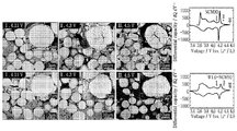
- Example 15 is a SEM image showing a cross-section after charging Comparative Example 1 and Example 1 of the present invention to 4.11 V, 4.3 V, and 4.5 V, respectively, and d Q / d V graphs.
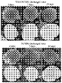
- Example 16 is a result of confirming the SEM image after performing a high-temperature stand test for 3 days, 7 days and 15 days at 60 ° C. for Comparative Example 1 and Example 1 of the present invention, respectively.
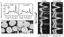
- Figure 17 is prepared and confirmed by using a Comparative Example 1 and Example 1 of the present invention as a pouch type full cell (full-cell), d Q / d V graph, cross-sectional SEM image after 500 cycles, and (003) peak ( Contour plots of 2 ⁇ selected to respond to reflections.
- the present invention provides a positive electrode active material.
- the positive electrode active material in the positive electrode active material comprising a secondary particle consisting of a group of a plurality of primary particles, the primary particle is provided on the surface of the secondary particle, the spinel structure at the end (spinel) It includes a first primary particle having, the primary particle may be made of lithium (Li), nickel (Ni), cobalt (Co), manganese (Mn) and doping element tungsten (W).
- the primary particles are formed in a layered structure, and a spinel structure may be included in a first region that is an end of the first primary particles.
- the first region may be formed to a depth of 5 nm to 50 nm inward from the outermost surface of the first primary particle.
- the secondary particles are formed in a spherical shape, and for the average radius of the secondary particles, the first region may be 0.2% to 1.3% in the center direction from the outermost surface of the secondary particles.
- the first primary particles are formed in a flake type having a major axis and a minor axis in cross section, and the first region is 0.5% to 4 with respect to the average length of the major axis of the primary particles. %.
- the first region increases, the length of the lattice parameters a of the first primary particle increases, and the length of c decreases. can do.
- the integration of the peak derived from the (003) plane to the integral intensity of the peak derived from the (104) plane The ratio of strength (003) / (104) is made from 1.05 to 1.75, and the ratio of (003) / (104) may decrease as the amount of the doping element increases.
- the secondary particles are composed of the formula Li x (Ni y M 1-yz W z ) O 2 , in the formula M is Co and Mn, x is 0.9 ⁇ 1.2, y is 0.85 ⁇ 0.95, z is 0.005 to 0.02, and after constant current charging at 4.4V cut-off, differential scanning calorimetry (DSC) analysis may show a heating peak of 190 ° C to 220 ° C.
- DSC differential scanning calorimetry
- the spinel structure provided in the first region may be formed before performing initial charging.
- the nickel (Ni) is provided in more than 85 mol%
- the doping element Phosphorus tungsten (W) may be provided in 0.1 mol% to 2 mol%.
- the nickel (Ni) may be 90 mol% or more.
- the BET specific surface area of the secondary particles is 0.15 m 2 / g to 0.6 m 2 / g, and as the content of the doping element increases, the BET specific surface area may increase.
- an embodiment of the present invention includes a positive electrode for a secondary battery including the positive electrode active material for a lithium secondary battery described above.
- an embodiment of the present invention is the anode for a secondary battery described above; A negative electrode made of graphite or lithium metal; And a lithium secondary battery including an electrolyte solution.
- capacity retention compared to initial capacity may be 80% or more.
- embodiments of the present invention includes a battery module including the above-described lithium secondary battery as a unit cell.
- a battery pack including the above-described battery module, the battery pack is used as a power source of a medium-sized device, the medium-sized device is an electric vehicle, a hybrid electric vehicle, a plug-in hybrid electric vehicle and power storage It includes a battery pack that is selected from the group consisting of systems.
- a positive electrode active material for a lithium secondary battery having a layered structure and a positive electrode active material that maintains a stable micro structure without deteriorating life characteristics even after a long-term cycle by including a new structure on the outer surface, and lithium containing the same A battery can be provided.
- FIG. 1 is a view for explaining a positive electrode active material according to an embodiment of the present invention.
- FIG. 2 is a view showing an A-B cross section of the positive electrode active material according to the embodiment of the present invention shown in FIG. 1.
- FIG 3 is a view for explaining a positive electrode active material according to a modification of the embodiment of the present invention.
- FIG. 4 is a view for explaining the primary particles contained in the positive electrode active material according to an embodiment of the present invention.
- FIG 5 is an enlarged view of the primary particles constituting the secondary particles and the secondary particles according to an embodiment of the present invention.
- TEM 6 is a transmission electron microscope (TEM) of the crystal structure of the primary particles located on the surface of the positive electrode active material according to Example 1 of the present invention.
- FIG. 7 is an enlarged area a, b, c, and d of FIG. 6 and observed by HR TEM.
- FIG. 9 is an enlarged region a, b, and c of FIG. 8 and observed by HR TEM.
- 10A to 10C are SEM images according to Example 1, Example 2, and Comparative Example 1 of the present invention.
- Example 11 is an XRD graph according to Example 1, Example 2, and Comparative Example 1 of the present invention.
- Example 12 is a STEM image of Example 1 of the present invention, TEM image, HR-TEM image and FT image.
- FIG. 13 is a diagram showing each structure using an electron diffraction pattern.
- Example 14 is a graph showing the volume change according to the d Q / d V graph and cell voltage in the charge and discharge characteristics at 4.4 V of the positive electrode active material according to Example 1, Example 2 and Comparative Example 1 of the present invention.
- Example 15 is a SEM image showing a cross-section after charging Comparative Example 1 and Example 1 of the present invention to 4.11 V, 4.3 V, and 4.5 V, respectively, and d Q / d V graphs.
- Example 16 is a result of confirming the SEM image after performing a high-temperature stand test for 3 days, 7 days and 15 days at 60 ° C. for Comparative Example 1 and Example 1 of the present invention, respectively.
- Figure 17 is prepared and confirmed by using a Comparative Example 1 and Example 1 of the present invention as a pouch type full cell (full-cell), d Q / d V graph, cross-sectional SEM image after 500 cycles, and (003) peak ( Contour plots of 2 ⁇ selected to respond to reflections.
- a component when referred to as being on another component, it means that it may be formed directly on another component, or a third component may be interposed between them.
- a third component may be interposed between them.
- the thickness of the films and regions are exaggerated for effective description of the technical content.
- first, second, and third are used to describe various components, but these components should not be limited by these terms. These terms are only used to distinguish one component from another component. Thus, what is referred to as the first component in one embodiment may be referred to as the second component in other embodiments.
- first component in one embodiment may be referred to as the second component in other embodiments.
- second component in other embodiments.
- Each embodiment described and illustrated herein includes its complementary embodiments.
- 'and / or' is used to mean including at least one of the components listed before and after.
- the ratio of the first crystal structure in the specific portion is higher than the ratio of the second crystal structure, wherein the specific portion includes both the first crystal structure and the second crystal structure, and the specific portion
- the ratio of the first crystal structure is higher than that of the second crystal structure, and is interpreted to mean that the specific portion includes only the first crystal structure.
- the crystal system is a triclinic, monoclinic, orthorhombic, tetragonal, trigonal or rhombohedral, or hexagonal. , And seven of a cubic system.
- mol% in the present application specification, assuming that the sum of the remaining metals except lithium and oxygen in the positive electrode active material or the positive electrode active material precursor is 100%, indicates the content of any metal contained in the positive electrode active material or the positive electrode active material precursor. It is interpreted in the meaning indicated.
- FIG. 1 is a view for explaining a positive electrode active material according to an embodiment of the present invention
- Figure 2 is a view showing a cross section AB of the positive electrode active material according to the embodiment of the present invention shown in Figure 1
- Figure 3 is the present invention It is a view for explaining a positive electrode active material according to a modified example of the embodiment.
- the positive electrode active material may include a secondary particle 100 in which a plurality of primary particles are aggregated, wherein the secondary particle 100 comprises a first crystal structure (first crystal structure) and a second crystal structure.
- the first crystal structure and the second crystal structure may be different crystal systems.
- the first crystal structure may be a structure in which a spinel structure and a layered structure coexist
- the second crystal structure may be a layered structure.
- the secondary particles 100 may include a surface portion 110 and a center portion 120.
- the surface portion 110 may be a portion of the secondary particles 100 in which the ratio of the first crystal structure is higher than that of the second crystal structure.
- the central portion 120 may be a portion of the secondary particles 100 in which the ratio of the second crystal structure is higher than that of the first crystal structure.
- the surface portion 110 includes both the first crystal structure and the second crystal structure, the ratio of the first crystal structure is the ratio of the second crystal structure Higher, or according to another embodiment, the surface portion 110 may have only the first crystal structure.
- the central portion 120 includes both the first crystal structure and the second crystal structure, the ratio of the second crystal structure than the ratio of the first crystal structure High, or according to another embodiment, the central portion 120 may have only the second crystal structure.
- the surface portion 110 may surround at least a portion of the central portion 120.
- the surface portion 110 may be provided in a form that completely surrounds the central portion 120.
- the surface portion 110 surrounds a portion of the central portion 120, the central portion 120 is a portion of the surface of the positive electrode active material 100 Can be configured.
- the surface of the secondary particle 100 and a portion adjacent to the surface are mainly or completely provided in a form in which a spinel structure and a layered structure coexist, at the center and the center of the secondary particle 100
- the adjacent portion may have a predominantly or completely layered structure.
- the spinel structure and the layered structure coexist, and the center of the secondary particle 100 and a portion adjacent to the center In, only layered structures can be observed.
- the ratio of the central portion 120 may be higher than the ratio of the surface portion 110.
- the ratio of the second crystal structure may be higher than that of the first crystal structure.
- the portion having the first crystal structure (or the surface portion 110) and the portion having the second crystal structure (or the central portion 120) may be made of the same element as each other.
- the portion having the first crystal structure (or the surface portion 110) and the portion having the second crystal structure (or the central portion 120) are lithium, It can be formed of oxides including nickel, cobalt, manganese and tungsten.
- the secondary particles 100 may include nickel, cobalt, manganese, or at least one of aluminum), lithium, and doping elements.
- the doping element may include tungsten (W).
- the secondary particle 100 may be a metal oxide containing nickel, cobalt, manganese, lithium, the doping element, and oxygen.
- the technical idea according to the embodiment of the present invention may be applied to a positive electrode active material including various materials.
- the concentration of the doping element in the secondary particles 100 may be substantially (substantially) constant.
- the concentrations of the doping elements may be different from each other, or may have a concentration gradient.
- the positive electrode active material may be represented by ⁇ Formula 1> below.
- M1, M2, M3 is any one selected from nickel, cobalt, manganese, or aluminum, 0 ⁇ a ⁇ 1, 0 ⁇ b ⁇ 1, 0 ⁇ c ⁇ 1, 0 ⁇ d ⁇ 0.02, at least one of a, b, and c is greater than 0, and M1, M2, M3, and M4 may be different metals.
- M4 may be the doping element.
- the concentration of the metal other than the doping element in the secondary particle 100 may be substantially constant within the secondary particle 100.
- the other metal in the secondary particle 100 in addition to the doping element has a concentration gradient in the whole particle, or a concentration gradient in a part of the particle, from the center to the surface direction.
- the secondary particles 100 may include a core portion, and a shell portion having a different concentration of metal from the core portion.
- FIG. 4 is a view for explaining the secondary particles included in the positive electrode active material according to an embodiment of the present invention and the primary particles constituting the secondary particles.
- the positive electrode active material may include primary particles 30 and secondary particles in which the primary particles 30 are aggregated.
- the primary particles 30 may extend in a direction radiated toward the surface 20 of the secondary particles in an area inside the secondary particles.
- One region inside the secondary particle may be the central portion 10 of the secondary particle.
- the primary particles 30 may be provided in a flake type, and a cross-section of the primary particles 30 may cover the surface 20 of the secondary particles in the region inside the secondary particles. It may be in the form of a rod shape extending toward the rod.
- the primary particles 30 having the shape of the rod that is, between the primary particles 30 extending from the central portion 10 of the secondary particles in the direction D of the surface portion 20.
- Metal ions for example, lithium ions
- electrolytes may be provided. Accordingly, the positive electrode active material according to an embodiment of the present invention, the charge and discharge efficiency of the secondary battery can be improved.
- the primary particles 30 relatively adjacent to the surface 20 of the secondary particles rather than the primary particles 30 relatively adjacent to the center 10 inside the secondary particles, the In the direction from the center 10 inside the secondary particles toward the surface 20 of the secondary particles, it may have a longer length.
- the length of the primary particles 30 is adjacent to the surface 20 of the secondary particles , Can be increased.
- the plurality of primary particles 30 include first type particles having only the first crystal structure, second type particles having only the second crystal structure, and the first portion 30a having the first crystal structure, And third type particles simultaneously including the second portion 30b having the second crystal structure.
- the ratio of the first portion 30a when the primary particle has the first portion 30a and the second portion 30b at the same time, in the primary particle, the ratio of the first portion 30a , It may be lower than the ratio of the second portion (30b).
- first portion 30a and the second portion 30b may be represented by the same chemical formula, or the first portion 30a and the second portion 30b may contain the same elements as each other. .
- the third type particles are provided on the surface 20 of the secondary particles, and the first portion 30a of the third type particles is the surface 20 of the secondary particles Located in, the first portion 30a constitutes the surface portion 110 of the secondary particle 20, and the second portion 30b of the third type particle is the secondary particle 20 It can be located inside.
- an embodiment of the present invention relates to a positive electrode active material including a secondary particle composed of a plurality of primary particles, the primary particle is provided on the surface of the secondary particle, spinel ( It includes a first primary particle having a spinel) structure, the primary particles are lithium (Ni), nickel (Ni), cobalt (Co), manganese (Mn) and a lithium secondary battery anode made of doping element tungsten (W) Contains active materials.
- the secondary particles may be composed of a plurality of primary particle groups, and among the primary particles provided on the surface of the secondary particles, the primary particles may include first primary particles having a spinel structure at the distal end.
- the primary particles have a layered structure, and a spinel structure may be included in a first region that is an end of the first primary particles.
- the spinel structure provided in the first region may be formed before performing initial charging.
- the secondary particles are composed of Li x (Ni y M 1-yz W z ) O 2 of Formula 2 , in the formula M is Co and Mn, x is 0.9 to 1.2, y is 0.85 to 0.95, and z May be 0.005 to 0.02.
- M may mean Mn, Co, and if M 1-yz is Mn a1 and Co a2 , (1-yz) may have the same value as (a1 + a2).
- a differential scanning calorimeter (DSC) analysis may exhibit a heating peak of 190 ° C to 220 ° C.
- the heating peak may be 195 °C to 220 °C, more preferably 195 °C to 200 °C.
- the nickel-based composite compound is composed of only a layered structure, and the spinel structure that was not present in the charge-discharge structure is formed, resulting in non-uniformity between the existing layered structure and the spinel structure irregularly formed in the course of the cycle.
- the stability of the microstructure of the secondary particles constituting the positive electrode active material was reduced, thereby causing a problem in that cycle characteristics, stability, and the like were lowered.
- the positive electrode active material according to the present embodiment has a structure as shown in Chemical Formula 2, and includes the doping element tungsten (W) in a predetermined range, and can improve the stability of secondary particles by applying a novel manufacturing method.
- the positive electrode active material according to this embodiment may be provided with a spinel structure on the surface of the positive electrode active material before the first charge and discharge.
- the positive electrode active material may be formed of a substantially spherical secondary particle formed by aggregation of a plurality of primary particles, and is located on the surface portion of the secondary particle among the primary particles, and at the same time, the first primary particle having a spinel structure at the end. It may include.
- the first primary particles may correspond to 80% or more of the primary particles provided on the surface of the secondary particles, preferably 90% or more, and more preferably primary particles provided on the surface of the secondary particles The whole may be provided in the form of first primary particles.
- the first primary particles are provided on the surface of the secondary particles, and at the same time, a first region having a spinel structure may be arranged to be provided on the surface of the secondary particles.
- the first region may be formed to a depth of 5 nm to 50 nm from the outermost surface of the first primary particle inward.
- the first region may be formed from 5 nm to 50 nm with a depth substantially perpendicular to the inside from the outermost surface of the first primary particle.
- the first region may be formed from 10 nm to 50 nm with a depth substantially perpendicular to the inside from the outermost surface of the first primary particles, and more preferably 20 nm to 30 nm.
- the secondary particles are formed in a spherical shape, and for the average radius of the secondary particles, the first region may be 0.2% to 1.3% in the center direction from the outermost surface of the secondary particles.
- the first region is formed to less than 0.2% in the center direction from the outermost surface of the secondary particles, the cycle characteristics of the secondary battery decreases, and when it exceeds 1.3%, the lithium ion transfer efficiency decreases and the initial charge / discharge efficiency decreases.
- the second region may be 0.2% to 0.9% in the center direction from the outermost surface of the primary particles, and more preferably 0.4% to 0.7%.
- the first primary particles may be formed in a flake type having a long axis and a short axis, and the first region may be 0.5% to 4% with respect to the average length of the long axes of the first primary particles. have.
- the first region is less than 0.5% with respect to the average length of the long axis of the first primary particle, the first region is difficult to form with a uniform thickness in the first primary particle, and cycle performance may be deteriorated, which may cause problems. If it is more than 4%, the thickness of the first region may be increased and the capacity may be reduced.
- the first region may be 1% to 4% with respect to the average length of the long axis of the first primary particles, and more preferably 1% to 3%.
- the first primary particle increases in the first region as the content of the doping element increases, the length of the lattice parameters a of the first primary particle increases, and the length of c decreases.
- the positive electrode active material according to the present embodiment may be a layered structure compound, and as the content of the doping element tungsten (W) increases, the first region in which the spinel structure and the layered structure are mixed tends to increase. Can be represented.
- the first primary particles may be controlled to have a flake shape sharper by the doping element.
- the lattice parameter a of the first primary particles is parallel to the direction toward the center of the secondary particles, and a may be increased but c may be decreased. In the lattice parameter of the first primary particle, by increasing a, lithium ions can be more easily moved to the center of the secondary particle, thereby improving charging and discharging efficiency.
- the BET specific surface area of the secondary particles is 0.15 m 2 / g to 0.6 m 2 / g, and as the content of the doping element increases, the BET specific surface area may increase.
- the BET specific surface area of the secondary particles constituting the positive electrode active material is 0.15 m2 / g to 0.6 m2 / g, and the BET specific surface area is within the aforementioned range as the content of the doping element increases.
- a strain may be formed in the relationship between the penetration of the electrolyte and the surface to deform the microstructure or promote the formation of a microcracks connected from the surface portion of the secondary particles to the center portion.
- the BET specific surface area may be 0.35 m 2 / g to 0.6 m 2 / g, and more preferably 0.35 m 2 / g to 0.45 m 2 / g.
- the spinel structure provided in the first region may be formed before performing initial charging.
- the commonly known spinel structure is a structure not found before filling in a layered structure compound.
- the spinel structure may be formed and provided before performing the initial charging.
- the nickel (Ni) is provided in an amount of 85 mol% or more, and the doping element tungsten (W) is 0.1 mol% to 2 mol% may be provided.
- the content of the tungsten (W) is less than 0.1 mol%, the first region due to the addition of tungsten (W) is not sufficiently formed, and thus the improvement of life characteristics, etc. is negligible. It can degrade and cause problems.
- the nickel (Ni) may be 90 mol% or more, and more preferably, the nickel (Ni) may be 90 mol% to 95 mol%.
- the doping element tungsten (W) may be 0.5 mol% to 2 mol%, and more preferably, tungsten (W) may be 0.5 mol% to 1 mol%.
- the positive electrode active material may be a positive electrode active material used in a lithium secondary battery having a layered structure, and the nickel may be 90 mol% or more.
- the nickel (Ni), cobalt (Co), manganese (Mn) is provided in a molar ratio of 8.5: 0.75: 0.75 and may further include a doping element, more preferably, the nickel (Ni ), Cobalt (Co), manganese (Mn) is provided in a molar ratio of 9: 0.5: 0.5, and may further include a doping element.
- N 2 gas was supplied to the reactor at a rate of 6 liters / minute, and the reactor was stirred at 350 rpm while maintaining the temperature at 40 ° C.
- Nickel sulfate aqueous solution NiSO 4 6H 2 O, Samjeon Chemical
- cobalt sulfate aqueous solution CoSO 4 7H 2 O, Samjeon Chemical
- manganese sulfate aqueous solution MnSO 4 H 2 O, Samjeon Chemical
- nickel (Ni), cobalt (Co ) And manganese (Mn) were mixed in an amount such that the molar ratio was 90: 5: 5 to prepare a 2M metal solution.
- WO 3 in the form of powder was dissolved in 4.0 mol / L of NaOH (aq.) To dissolve to 0.02 M to prepare a doping element solution (NaOH is 2 mol with respect to the total number of moles of Ni and Co. Mn).
- the prepared 2M concentration metal solution was continuously charged into the reactor at 0.561 liters / hour, ammonia solution (NH 4 OH, JUNSEI) at 16M concentration at 0.08 liters / hour, and a doping element solution at 0.60 liters / hour.
- ammonia solution NH 4 OH, JUNSEI
- a doping element solution 0.60 liters / hour.
- the pH in the reactor was checked, and NaOH (aq.) Solution was added and adjusted so that the pH was maintained in the reactor.
- Ni: Co: Mn aqueous solution of nickel sulfate aqueous solution (NiSO 4 6H 2 O, Samjeon Chemical), cobalt sulfate aqueous solution (CoSO 4 7H 2 O, Samjeon Chemical), manganese sulfate aqueous solution (MnSO 4 H 2 O, Samjeon Chemical)
- a metal sulfide aqueous solution was prepared by mixing in a molar ratio of 85: 7.5: 7.5, and a doping element solution prepared by dissolving to a concentration of 0.01 M by adding WO 3 in powder form in 4.0 mol / L of NaOH (aq.) was used.
- a metal composite hydroxide of [Ni 0.84 Co 0.075 Mn 0.075 W 0.005 ] (OH) 2 was prepared in the same manner as in Example 1 except for the use.
- Ni: Co: Mn aqueous solution of nickel sulfate aqueous solution (NiSO 4 6H 2 O, Samjeon Chemical), cobalt sulfate aqueous solution (CoSO 4 7H 2 O, Samjeon Chemical), manganese sulfate aqueous solution (MnSO 4 H 2 O, Samjeon Chemical) [Ni 0.94 Co 0.025 Mn 0.025 W 0.01 ] (OH) 2 metal composite hydroxide was prepared in the same manner as in Example 1, except that a metal sulfide aqueous solution was prepared by mixing in a molar ratio of 95: 2.5: 2.5.
- Ni: Co: Mn aqueous solution of nickel sulfate aqueous solution (NiSO 4 6H 2 O, Samjeon Chemical), cobalt sulfate aqueous solution (CoSO 4 7H 2 O, Samjeon Chemical), manganese sulfate aqueous solution (MnSO 4 H 2 O, Samjeon Chemical)
- a doped element solution prepared by mixing in a molar ratio of 95: 2.5: 2.5 to prepare and use an aqueous metal sulfide solution, and dissolving it to 0.01M by adding WO 3 in powder form in 4.0 mol / L NaOH (aq.)
- a metal composite hydroxide of [Ni 0.94 Co 0.025 Mn 0.025 W 0.005 ] (OH) 2 was prepared in the same manner as in Example 1 except for the use.
- a metal composite hydroxide of [Ni 0.90 Co 0.05 Mn 0.05 ] (OH) 2 was prepared in the same manner as in Example 1, except that the doping element solution was added.
- Ni: Co: Mn aqueous solution of nickel sulfate aqueous solution (NiSO 4 6H 2 O, Samjeon Chemical), cobalt sulfate aqueous solution (CoSO 4 7H 2 O, Samjeon Chemical), manganese sulfate aqueous solution (MnSO 4 H 2 O, Samjeon Chemical) [Ni 0.85 Co 0.075 Mn 0.075 ] (OH) 2 metal composite hydroxide in the same manner as in Example 1, except that a metal sulfide aqueous solution was prepared by mixing in a molar ratio of 85: 7.5: 7.5 and a doping element solution was added. Was prepared.
- Ni: Co: Mn aqueous solution of nickel sulfate aqueous solution (NiSO 4 6H 2 O, Samjeon Chemical), cobalt sulfate aqueous solution (CoSO 4 7H 2 O, Samjeon Chemical), manganese sulfate aqueous solution (MnSO 4 H 2 O, Samjeon Chemical) [Ni 0.95 Co 0.025 Mn 0.025 ] (OH) 2 metal composite hydroxide in the same manner as in Example 1, except that a metal sulfide aqueous solution was prepared by mixing in a molar ratio of 35: 2.5: 2.5 and a doping element solution was added. Was prepared.
- the prepared positive electrode active materials of Examples 1 and 2 and Comparative Example 1 were confirmed by SEM (Nova Nano SEM 450, FEI) in the form of powder particles.
- In-situ XRD data using full cells were measured using transmission mode (Empyrean, PANalytical).
- the pouch-shaped full cells prepared by Examples 1, 2, and Comparative Example 1 were analyzed without disassembly or disassembly.
- the pouch type full cell was charged with a constant current density of 10 mA / g (0.05C).
- the XRD pattern was continuously detected every 40 minutes with a detector (PIXcel 1D, PANalytical).
- the microstructures of the prepared positive electrode active materials of Examples 1 and 2 and Comparative Example 1 were confirmed by TEM (JEOL 2100F, JEOL).
- TEM samples were prepared by a focused ion beam method (FIB, SCIOS, FEI).
- FIB focused ion beam method
- the positive electrode charged in a different filling state was immediately washed with dimethyl carbonate and dried in a vacuum in an argon condition glove box.
- the electrode was cut using an ion beam cross-sectional polisher (CP, JEOL SM-09010).
- the positive electrode active material in the form of powder of Example 1, Example 2 and Comparative Example 1 in 0.6 g of N -methyl pyrrolidone, poly (vinylidene fluoride) and carbon black was uniformly mixed in a weight ratio of 90: 4.5: 5.5, respectively, to prepare a positive electrode slurry.
- the prepared anode slurry was coated on an aluminum foil, and then roll-pressed and dried in vacuum to prepare an anode.
- the loading level of the positive electrode active material (loading level, which means that when the aluminum foil coated with the positive electrode active material is sampled in a square of 1 cm 2, the weight of the positive electrode active material is 5 mg / cm 2)
- the loading level of the positive electrode active material was 8.5 mg / cm 2.
- the half cell was manufactured as a 2032-coin type half cell (hereinafter, coin cell) using Li as a cathode.
- the full cell was prepared to use graphite as a negative electrode and an N / P ratio of 1.15 to 1.20.
- the manufactured half-cell and full-cell are charged to 4.3V and discharged to 2.7V at a constant current of 90mA / g (0.5C) at 30 °C to test charging and discharging (hereinafter 2.7V-4.3V), or to 4.4V.
- Charging and discharging to 2.7V were performed to test charging and discharging (hereinafter, 2.7V-4.4V).
- electrochemical impedance measurement was performed using a multi-channel potentiometer (Bio-Logic, VMP3) with a voltage amplitude of 10 mV in the frequency range of 1.0 mHz to 1.0 MHz with the manufactured coin cell.
- Laminate pouch-type full cells using mesocarbon microbead graphite (Osaka Gas) as a cathode were prepared to confirm long-term cycle performance using the anodes prepared according to Examples 1 and 2 and Comparative Examples.
- the N / P ratio of the full cell was 1.15 to 1.20.
- the loading level of the positive electrode active material was approximately 8.5 mg / cm 2.
- the cell was charged at 4.3V with a constant current of 200mA / g (1C) at 25 ° C and discharged at 3.0V to perform charging and discharging (hereinafter, 3.0V-4.3V).
- Table 1 shows the chemistry of the positive electrode active materials prepared according to Examples 1 to 6 and Comparative Examples 1 to 3 using an inductively coupled plasma-optical emission spectroscopy (ICP-OES). It is the result of confirming the components and confirming the capacity characteristics using a half cell at 2.7V-4.4V.
- ICP-OES inductively coupled plasma-optical emission spectroscopy
- Example 1 Example 2
- Comparative Example 3 The nickel (Ni) content in Example 1, Example 2 and Comparative Example 3 corresponds to the intermediate values for Examples 3 to 6 and Comparative Examples 2 and 3, so that the Examples 1 and 2 And the following results by Comparative Example 3 will behave similarly for these remaining examples and comparative examples.
- Table 2 shows the results of analyzing the average chemical composition of the positive electrode active materials prepared according to Examples 1 and 2 and Comparative Example 1 using an inductively coupled plasma-optical emission spectroscopy (ICP-OES).
- ICP-OES inductively coupled plasma-optical emission spectroscopy
- Example 1 Chemical compositions analyzed by ICP-OES were each in Example 1 (W1.0-NCM90 is Li [Ni 0.896 Co 0.047 Mn 0.047 W 0.01 ] O 2
- Example 2 (W0.5-NCM90) is Li [Ni 0.899 Co 0.048 Mn 0.048 W 0.005 ] O 2
- Comparative Example 1 (NCM90) is Li [Ni 0.902 It was confirmed that Co 0.049 Mn 0.049 ] O 2 , thereby confirming that each positive electrode active material was synthesized so that the design values matched well.
- Figure 6 is a transmission electron microscope (TEM) of the crystal structure of the primary particles located on the surface of the positive electrode active material according to Example 1 of the present invention
- Figure 7 is a, b, c, d regions of Figure 6 It is the result observed by HR TEM enlarged.
- FIG. 8 is a TEM image of the positive electrode active material prepared according to Comparative Example 1
- FIG. 9 shows an HR TEM image of regions a, b, and c of FIG. 8 as a diffraction pattern obtained by FFT (fourier filtered transformation) transformation.
- FFT fourth filtered transformation
- Example 6 and 7 confirm the state before charging of Example 1, it was confirmed that generally shows a different pattern from the positive electrode active material of a layered structure.
- the positive electrode active material having a general layered structure when a Li + vacancy is present in a charged state, a spinel structure is formed locally in a case where a charge / discharge cycle is performed, or is left at a high temperature, etc. No structure was found.
- a spinel structure was found in a fresh state immediately after preparation, which is not formed irregularly but is formed at the end of the primary particles present in the surface of the secondary particles at a specific position. I could confirm that.
- Example 1 As a result, in the case of Example 1, it was confirmed that the whole portion was formed in a layered structure, and a portion in which the layered structure and the spinel structure coexisted was formed on the surface. On the other hand, referring to FIGS. 8 and 9, in the case of Comparative Example 1, it was confirmed that the spinel structure did not occur and only the layered structure was formed.
- a half cell was prepared using the positive electrode active material according to Example 1, Example 2, and Comparative Example 1, and the voltage cutoff was 2.7V-4.3V, and the discharge capacity was measured at 0.1C and 30 ° C. The cut-off was checked at 2.7-4.3V, 0.5C, and 30 ° C, and the results are shown in Table 3, Table 4, and Table 5.
- Table 4 is the result of the cycle proceeding to 2.7V-4.3V
- Table 5 is the result of the cycle proceeding to 2.7V-4.4V
- Examples 1, 2 was charged to 4.3V and the cycle proceeded to 4.4V It was confirmed that all of the cycle anodes charged and advanced were superior to Comparative Example 1.
- 10A to 10C are SEM images of particles according to Example 1, Example 2, and Comparative Example 1 of the present invention.
- Comparative Example 1 it was confirmed that the thickness of the primary particles became thin as the doping element tungsten (W) was added in the order of Example 2 and Example 1.
- W doping element tungsten
- the specific surface areas of Examples 1, 2, and 1 were 0.388 m2 / g, 0.351 m2 / g, and 0.315 m2 / g, respectively. That is, it was confirmed that the specific surface area of Example 1 in which tungsten was most doped showed the largest value, and the specific surface area of Comparative Example 1 was the smallest.
- Example 11 is an XRD graph according to Example 1, Example 2, and Comparative Example 1 of the present invention, showing an area of 35 ° to 45 °.
- the first graph in FIG. 11 is an XRD pattern showing intensity ratios of (003) / (104) of Example 1 (W1.0-NCM90), Example 2 (W0.5-NCM90), and Comparative Example 1 (NCM90).
- the graph is an enlarged view selecting a range of 35 ° to 45 °.
- the XRD pattern of each positive electrode active material of Examples 1, 2 and Comparative Example 1 did not show impurity phases, and a hexahedral crystal structure having an R3m space group was shown.
- the (108) / (110) peaks of the XRD pattern were clearly separated, and Comparative Example 1 showed high crystallinity.
- the (108) and (110) peaks showed a tendency to gradually merge.
- the peak intensity ratio of (003) / (104) indicating the mixing degree of the positive electrode in a nickel-rich NCM positive electrode active material different from LiNiO 2 is 1.89 in Comparative Example, 1.60 in Example 2, and 1.27 in Example 1, which tends to gradually decrease.
- Example 1 corresponds to a decrease in the (003) / (104) peak intensity ratio of 2.50% and Example 1 is 4.44%).
- the enlarged XRD pattern confirmed that the peaks were extended to both sides, indicating that the tungsten (W) expanded in proportion to the doped fraction.
- FIG. 12 is a STEM image (top left), TEM image (top middle), HR-TEM image (bottom left) and FT image (top right, bottom right) of Example 1 of the present invention.
- FIG. 12 is a transmission electron microscopy (TEM) analysis in order to confirm the crystallinity of the first primary particles in Example 1 observed in XRD. After the primary particles provided on the outermost surface of the secondary particles were selected, the crystallinity of the entire primary particles selected through the SAED pattern was confirmed.
- TEM transmission electron microscopy
- the STEM image of Example 1 shows that the primary particles are significantly smaller and densely aggregated at the center than the surface of the secondary particles, which corresponds to SEM and XRD results.
- the TEM image of the primary particle and the SAED (100-zone selected-area electron diffraction) pattern in the surface area of the secondary particle of Example 1 show that the primary particle is thin and long, and the longitudinal axis of the primary particle is united. Indicates that the cell is in a direction parallel to the a-direction.
- the SAED pattern showed faint additional dots (indicated by yellow circles) that did not appear in the R3m space group. Additional diffraction points appearing faintly indicate that either strong cation ordering or crystal symmetry changes are present locally.
- the lattice fringe appeared on the surface of the secondary particle was different from the 100-zone image of a typical layered structure.
- a FT (Fourier-transformed) image of the surface portion of Example 1 it was confirmed that the first image (I region) in the lower left was represented by an Fd 3 m spinel structure. It was confirmed that the FT image of the II region close to the I region showed weaker diffraction points than the I region, the additional peaks disappeared completely in the III region located further down, and only the R3m diffraction pattern appeared. That is, it was confirmed that the primary particle of Example 1 includes a portion structurally deformed by tungsten (W) doping at the end, and is formed to a depth of approximately 30 nm at the end of the primary particle.
- W tungsten
- the spinel structure in a layered structure, is partially formed by the collapse of the structure, and it is known that this occurs mainly from oxygen site defects due to oxygen generation.
- the spinel structure is formed in such a layered structure occurs when the secondary battery using the positive electrode active material of nickel-rich NCM is cycled at a high rate. In this way, the spinel structure partially formed in the layered structure means structural deterioration of the anode.
- the spinel structure observed in the positive electrode active material as in Example 1 was generated before the cycle, and is different from the phase exhibited by the structural deterioration of the positive electrode active material of the nickel-rich NCM, which is a conventional layered structure. It is determined that lithium (Li) ions and nickel (Ni) ions are partially mixed inside as an intermediate state between (rocksalt) structures.
- Example 1 it was confirmed that the first primary particles provided on the surface of the secondary particles and having a spinel structure at the ends were layered as a whole and at the same time, the spinel structures were uniformly present in the first region at the ends. It was confirmed that the first region was provided at approximately 30 nm in the depth direction from the outermost surface of the first primary particle.
- FIG. 13 is a diagram showing each structure using an electron diffraction pattern.
- a spinel structure, or a rocksalt phase may be generated in cation intermixing.
- the structure of the positive electrode active material having a layered structure according to the degree of cation intermixing is layered.
- the phase changes from layer to cation-ordered to spinel structure to lacalt structure.
- the layered structure shown at the bottom left of FIG. 13 indicates that lithium and transition metal are distinguished from each other, and the lock salt structure shown at the bottom right of FIG. 13 indicates that lithium and transition metal are irregularly mixed inside.
- the spinel structure located on the surface of the secondary particle and formed at the end of the primary particle has a structure closer to the lac salt structure than the layered structure formed independently as shown in the upper part of FIG. 13. It is judged that it is possible to improve the cycle stability by stabilizing the surface of the secondary particles in a partially mixed form.
- Example 14 is a graph showing the volume change according to the d Q / d V graph and cell voltage in the charge and discharge characteristics at 4.4 V of the positive electrode active material according to Example 1, Example 2 and Comparative Example 1 of the present invention.
- Example 14 is a result of evaluating as a half cell, the primary charging and discharging for Example 1, Example 2, and Comparative Example 1 with a constant current of 0.1C at 2.7 V discharge, 4.3 V or 4.4 V charging conditions at 30 ° C. The capacity was checked, and the cycle was performed at 0.5 C (90 mA) to confirm the cycle characteristics.
- Table 6 shows the lattice constant according to the charging voltage measured by in-situ XRD in Example 1 and Comparative Example 1.
- Example 1 the H2-H3 phase transitions are almost similar when the single dose (1 cycle) and the 100 dose (lcycle) are confirmed, whereas in Comparative Example 1, there is a difference.
- Comparative Example 1 there is a difference.
- the in situ-XRD it was confirmed that the cell shrinkage of Example 1 was reduced compared to Comparative Example 1 in the 4.2V region, where it can be considered that the lifespan is mainly started due to the occurrence of microcracks.
- Examples 1 and 2 and Comparative Example 1 the doped tungsten (W) fraction slightly decreased as the doped tungsten (W) fraction increased, and the cycle characteristics of Examples 1 and 2 compared to Comparative Example 1 Excellent was confirmed.
- Examples 1 and 2 after 100 cycles showed capacity retention rates of 96.0% and 93.0%, respectively, while Comparative Example 1 showed 86.0%.
- one of the main causes of the rapid capacity reduction of the nickel-rich layered positive electrode active material generated in the course of the cycle is a phenomenon in which microcracks are increased in the secondary particles, and these microcracks are charged at the last stage during charging. It is known to be caused by sudden anisotropic volume change.
- Comparative Example 1 undergoes a continuous phase change such as H1 (hexagonal 1)-> M (monoclinic)-> H2 (hexagonal 2)-> H3 (hexagonal 3) during the charging process.
- H1 hexagonal 1-> M (monoclinic)-> H2 (hexagonal 2)-> H3 (hexagonal 3)
- the last H2-> H3 greatly affects the sudden change in volume of anisotropy.
- the NCM90 positive electrode active material means irreversible structural damage due to anisotropic volume change.
- Example 1 W1.0-NCM90
- Example 15 is a SEM image showing a cross-section after charging Comparative Example 1 and Example 1 of the present invention to 4.11 V, 4.3 V, and 4.5 V, respectively, and d Q / d V graphs.
- FIG. 15 used samples prepared after primary charging. Referring to FIG. 16, while charging the electric potential while increasing the potentials to 4.11 V, 4.3 V, and 4.5 V, Comparative Example 1 (top image) and Example 1 (bottom image) were confirmed. It occurred, and it was confirmed that the microcracks increased at 4.5V. On the other hand, in the case of Example 1, it was confirmed that micro-cracks did not occur at 4.3V and 4.5V.
- Comparative Example 1 showed fine hairline generated from the center of the secondary particles, but neither of microcracks occurred in both Comparative Example 1 and Example 1.
- microcracks were generated in Comparative Example 1, but microcracks were not generated in Example 1.
- the micro-cracks that were severely generated at the center propagated to the surface of the secondary particles, thereby forming a microchannel through which the electrolyte could penetrate into the center of the secondary particles.
- the electrolyte penetrates through the microchannel, and the penetrated electrolyte attacks the inner surface of the secondary particles to form an impurity layer of high resistance in the course of the cycle, thereby reducing electron conductivity.
- Example 1 In Comparative Example 1 charged at 4.5 V, the secondary particles were almost destroyed by the microcracks, but in the case of Example 1, microcracks were still not observed. That is, Example 1, H2-> H3 by tungsten (W) doping to reduce the phase transition, thereby minimizing the local concentration of the strain, thereby confirming that it inhibits the formation of microcracks.
- W tungsten
- Table 7 is a graph showing the resistance values of Example 1 and Comparative Example 1 according to the charge / discharge voltage and the number of cycles.
- Example 1 In the case of Example 1, it was confirmed that the tungsten (W) is doped, and the impedance of the anode is significantly reduced at 4.3V and 4.4V. Comparing Example 1 and Comparative Example 1, it can be seen that when the cut-off voltage increases from 43V to 4.4V, the relative impedance difference becomes larger.
- Example 1 micro-cracks are suppressed during the cycle process, thereby preventing penetration of the electrolyte, thereby preventing internal damage of secondary particles, whereas Comparative Example 1 gradually increases the micro-cracks during the cycle process, Through this, when the electrolyte penetrates, the impedance increases gradually.
- the relatively low Rct of Example 1 in the early stage of the cycle minimizes the influence of the electrolyte and contributes to the stabilization of the surface chemistry by the spinel structure formed on the surface of the secondary particles already formed before charging and discharging.
- Table 8 shows the results of the differential scanning calorimetry (DSC) of Comparative Example 1 and Example 1 of the present invention.
- Comparative Example 1 Example 1
- Example 2 was confirmed using electrolyte 1.2 M LiPF 6 , EC / EMC (3: 7 v: v), and 2wt% VC, 4.3V and 4.4V, respectively. It was checked by charging with. When the battery was charged to 4.4V compared to 4.3V, it was confirmed that the thermal safety was lowered, and it was confirmed that Example 1 had a lower degree of thermal safety than Comparative Example 1. That is, in the case of Example 1 to which tungsten (W) was added, it was confirmed that the thermal safety was superior to that of Comparative Example 1, and the degree of thermal safety was lowered even when charged at a high voltage.
- W tungsten
- Comparative Example 1 exhibited a high exothermic peak of 191.2 ° C with exotherm of 1243 J / g, while Example 1 had a very low reaction heat of 1027 J / g and a start of thermal reaction of 201.9 ° C. Appeared relatively delayed.
- Example 1 At 4.4 V, the exothermic peak of Comparative Example 1 was 186.8 ° C (1865 J / g), and Example 1 was found to be 198.6 ° C (1442 J / g) with a greater difference than 4.3 V.
- the exothermic reaction is mainly caused by the surface portion of the secondary particles exposed to the electrolyte.
- the spinel structure of Example 1 suppresses microcracks to prevent the electrolyte from penetrating into the secondary particles, thereby reducing the contact of the secondary particles with the electrolyte.
- Such thermal stability means that the spinel structure of Example 1 improves not only chemical stability but also mechanical stability.
- Table 9 shows the results of performing the high temperature storage test for 60 days at 3 days and 7 days at 60 ° C for Comparative Example 1 and Example 1 of the present invention, and FIG. 16 confirmed the SEM image after completely discharging it. Is the result.
- Example 1 and Comparative Example 1 the chemical stability of Example 1 and Comparative Example 1 was confirmed by performing an hourly elevated temperature aging test. As the time of impregnation in Comparative Example 1 and Example 1 increased to 3 days, 7 days and 15 days, the dose was decreased, but it was confirmed that the degree of decrease was less in Example 1 than in Comparative Example 1. In addition, referring to the cross-sectional SEM image taken after discharge, it was confirmed that in Comparative Example 1, the microcracks increased as time increased, whereas in Example 1, microcracks hardly occurred even when the time increased.
- the anode of the nickel-rich layered structure has a proportional decrease in capacity as the standing time increases in a high temperature standing test, and a nickel-like impurity phase and oxygen release increase, resulting in structural problems.
- Comparative Example 1 and Example 1 The positive electrode of Comparative Example 1 and Example 1, which was completely charged and severely delithiated, was impregnated in the same electrolyte solution as that used in the cycle, and stored at 60 ° C for 3 days and 7 days and 15 days. Thereafter, Comparative Example 1 and Example 1 were manufactured into coin-type half cells using parts such as a new cathode, and the capacity was confirmed. As a result, Comparative Example 1 had a capacity of 19.6% after 7 days and 39.5% after 15 days compared to the initial capacity. On the other hand, Example 1 showed only a loss in capacity compared to the initial dose, 11.3% after 7 days and 23.9% after 15 days.
- Comparative Example 1 appears microcracks across the surface of the secondary particles after 3 days, and inside the secondary particles, the hairline along the boundary of the primary particles Micro-cracks such as (hair line) appeared fine.
- Comparative Example 1 micro-cracks occurred, and the primary particles were separated from each other, and after 15 days, the secondary particles were observed to be almost destroyed by formation of large micro-cracks on both the surface and the center. Became.
- Table 10 shows the results of confirming the capacity according to the cycle at 4.3 V , which was prepared and confirmed as a pouch-type full-cell using Comparative Example 1 and Example 1 of the present invention, and a d Q / d V graph, 500 This is a contour plot of 2 ⁇ selected to correspond to a cross-sectional SEM image and a (003) peak after the cycle.
- Example 1 in a high potential Li + / Li coin cell, as a result of charging and discharging with a full cell at 4.3 V (cathode graphite) corresponding to 4.4 V, Example 1 has excellent life characteristics up to 500 cycles. It was confirmed that indicates. Similarly, Example 1 H2-> H3 phase transition was maintained without change even after 500 cycles, it was confirmed that the micro-cracks also did not occur. On the other hand, in Comparative Example 1, unlike Example 1, it was confirmed that as the charge and discharge progressed, the cell deteriorated and the life characteristics were reduced, and a large number of microcracks occurred in the SEM image after 500 cycles.
- Example 1 shows that the phase transition is smoothly maintained, and excellent in life characteristics.
- Figure 17 is prepared and confirmed by using a Comparative Example 1 and Example 1 of the present invention as a pouch type full cell (full-cell), d Q / d V graph, cross-sectional SEM image after 500 cycles, and (003) peak ( Contour plots of 2 ⁇ selected to respond to reflections.
- FIG. 17 a contour plot for selected 2 ⁇ corresponding to the (003) peak is shown.
- the (003) peak is initially moved to the left, H2 - with> in more than 4.0V ( ⁇ 18.3 °) to the phase transition starts H3 Comparative Example 1 (003) peak is higher H2 approximately 1.4 ° angle ( 003) Move to the H3 peak.
- the (003) H3 peak ( ⁇ 19.7 °) returns symmetrically to the initial position ( ⁇ 18.7 °), which means that the phase change is reversibly performed in the first cycle.
- Example 1 the H2-> H3 phase transition peak shifted from 18.3 ° to 19.7 ° without decreasing intensity, and no decline in peak shift was observed. That is, Example 1 can be confirmed that it exhibits excellent mechanical stability even after a long cycle, and is interpreted similarly to micro-cracks not occurring even in the cross-section of secondary particles after 500 cycles, which is the result of doping of tungsten (W). It is judged as an effect.
- Table 11 shows the XRD results of Comparative Example 1 and Example 1 and Example 2 of the present invention.
- the tungsten (W) according to the present embodiment is maintained at high temperature, life characteristics, It was confirmed that the thermal properties were all improved compared to the comparative example.
- the H2-H3 phase transition is irreversible, and micro-cracks are formed, resulting in deterioration of life, etc.
- high voltage, 4.4 Even when proceeding at V it was confirmed that the H2-H3 phase transition proceeds reversibly and that a stable phenomenon is not formed in which microcracks are not formed.
Landscapes
- Chemical & Material Sciences (AREA)
- Chemical Kinetics & Catalysis (AREA)
- Electrochemistry (AREA)
- General Chemical & Material Sciences (AREA)
- Engineering & Computer Science (AREA)
- Inorganic Chemistry (AREA)
- Materials Engineering (AREA)
- Manufacturing & Machinery (AREA)
- Composite Materials (AREA)
- Organic Chemistry (AREA)
- Battery Electrode And Active Subsutance (AREA)
Abstract
L'invention concerne un matériau actif de cathode pour une batterie secondaire au lithium, le matériau actif de cathode comprenant des particules secondaires composées d'une pluralité de groupes de particules primaires, les particules primaires étant disposées sur la partie de surface des particules secondaires, comprenant des premières particules primaires ayant une structure de spinelle aux extrémités de celles-ci, et étant composées de lithium (Ni), de nickel (Ni), de manganèse (Mn) et de tungstène (W) qui est un élément de dopage.
Priority Applications (2)
| Application Number | Priority Date | Filing Date | Title |
|---|---|---|---|
| US17/293,251 US20220020982A1 (en) | 2018-11-13 | 2019-11-13 | Cathode active material and lithium secondary battery comprising same |
| CN201980088465.8A CN113273002B (zh) | 2018-11-13 | 2019-11-13 | 阴极活性材料和包含其的锂二次电池 |
Applications Claiming Priority (4)
| Application Number | Priority Date | Filing Date | Title |
|---|---|---|---|
| KR10-2018-0138587 | 2018-11-13 | ||
| KR20180138587 | 2018-11-13 | ||
| KR1020190144342A KR102309288B1 (ko) | 2018-11-13 | 2019-11-12 | 양극활물질 및 이를 포함하는 리튬이차전지 |
| KR10-2019-0144342 | 2019-11-12 |
Publications (1)
| Publication Number | Publication Date |
|---|---|
| WO2020101331A1 true WO2020101331A1 (fr) | 2020-05-22 |
Family
ID=70731877
Family Applications (1)
| Application Number | Title | Priority Date | Filing Date |
|---|---|---|---|
| PCT/KR2019/015383 Ceased WO2020101331A1 (fr) | 2018-11-13 | 2019-11-13 | Matériau actif de cathode et batterie secondaire au lithium le comprenant |
Country Status (2)
| Country | Link |
|---|---|
| US (1) | US20220020982A1 (fr) |
| WO (1) | WO2020101331A1 (fr) |
Cited By (2)
| Publication number | Priority date | Publication date | Assignee | Title |
|---|---|---|---|---|
| CN114583152A (zh) * | 2020-12-02 | 2022-06-03 | Sk新技术株式会社 | 用于锂二次电池的正极活性物质及其制造方法 |
| EP4227269A1 (fr) * | 2022-01-14 | 2023-08-16 | SK On Co., Ltd. | Matériau actif de cathode, précurseur pour batterie secondaire au lithium, matériau actif de cathode pour batterie secondaire au lithium et batterie secondaire au lithium |
Families Citing this family (4)
| Publication number | Priority date | Publication date | Assignee | Title |
|---|---|---|---|---|
| KR102258083B1 (ko) | 2018-05-17 | 2021-05-27 | 삼성에스디아이 주식회사 | 리튬 이차 전지용 양극 활물질 및 이를 포함하는 리튬 이차 전지 |
| KR102791979B1 (ko) * | 2020-10-14 | 2025-04-08 | 주식회사 엘 앤 에프 | 양극 활물질용 복합 전이금속 전구체 및 그로부터 제조된 이차전지용 양극 활물질 |
| WO2023204077A1 (fr) * | 2022-04-21 | 2023-10-26 | パナソニックIpマネジメント株式会社 | Matériau actif d'électrode positive pour batteries secondaires à électrolyte non aqueux, et batterie secondaire à électrolyte non aqueux |
| WO2025198165A1 (fr) * | 2024-03-22 | 2025-09-25 | 주식회사 엘 앤 에프 | Matériau actif de cathode pour batterie secondaire |
Citations (5)
| Publication number | Priority date | Publication date | Assignee | Title |
|---|---|---|---|---|
| US20110076564A1 (en) * | 2009-09-30 | 2011-03-31 | Sanyo Electric Co., Ltd. | Positive electrode active material, method of manufacturing the positive electrode active material, and non-aqueous electrolyte secondary battery using the positive electrode active material |
| WO2012148157A2 (fr) * | 2011-04-26 | 2012-11-01 | 국립대학법인 울산과학기술대학교 산학협력단 | Matériau actif d'électrode positive pour pile au lithium rechargeable, son procédé de préparation et pile au lithium rechargeable le comprenant |
| KR20140034606A (ko) * | 2012-09-12 | 2014-03-20 | 삼성에스디아이 주식회사 | 복합양극활물질, 이를 채용한 양극과 리튬전지 및 그 제조방법 |
| JP2017084513A (ja) * | 2015-10-26 | 2017-05-18 | 住友金属鉱山株式会社 | 非水系電解質二次電池用正極活物質、および該正極活物質を用いた非水系電解質二次電池 |
| KR20170115939A (ko) * | 2016-04-08 | 2017-10-18 | 한양대학교 산학협력단 | 양극활물질, 그 제조 방법, 및 이를 포함하는 리튬이차전지 |
Family Cites Families (8)
| Publication number | Priority date | Publication date | Assignee | Title |
|---|---|---|---|---|
| GB9926538D0 (en) * | 1999-11-09 | 2000-01-12 | Kci Medical Ltd | Multi-lumen connector |
| CN101106194B (zh) * | 2007-07-12 | 2010-04-07 | 深圳市贝特瑞电子材料有限公司 | 锂离子电池正极材料磷酸钒锂的制备方法 |
| EP2466671A3 (fr) * | 2007-09-04 | 2012-08-22 | Mitsubishi Chemical Corporation | Poudre de composé à base de métal de transition au lithium, son procédé de fabrication, substance à séchage par atomisation servant de précurseur de frittage et électrode positive de batterie secondaire au lithium et batterie secondaire au lithium l'utilisant |
| JP5741932B2 (ja) * | 2011-06-01 | 2015-07-01 | 住友金属鉱山株式会社 | 非水系電解質二次電池用正極活物質の前駆体となる遷移金属複合水酸化物とその製造方法、及び非水系電解質二次電池用正極活物質の製造方法 |
| WO2013125021A1 (fr) * | 2012-02-24 | 2013-08-29 | 株式会社日立製作所 | Électrode destinée à une batterie rechargeable au lithium-ion et batterie rechargeable au lithium-ion |
| KR101777444B1 (ko) * | 2014-08-22 | 2017-09-11 | 주식회사 엘지화학 | 리튬이차전지 |
| CN107112515B (zh) * | 2014-10-28 | 2020-08-18 | 株式会社Lg 化学 | 锂二次电池用正极活性材料、其制备方法和包含其的锂二次电池 |
| JP6619562B2 (ja) * | 2015-04-24 | 2019-12-11 | 株式会社エンビジョンAescジャパン | 非水電解質二次電池 |
-
2019
- 2019-11-13 US US17/293,251 patent/US20220020982A1/en active Pending
- 2019-11-13 WO PCT/KR2019/015383 patent/WO2020101331A1/fr not_active Ceased
Patent Citations (5)
| Publication number | Priority date | Publication date | Assignee | Title |
|---|---|---|---|---|
| US20110076564A1 (en) * | 2009-09-30 | 2011-03-31 | Sanyo Electric Co., Ltd. | Positive electrode active material, method of manufacturing the positive electrode active material, and non-aqueous electrolyte secondary battery using the positive electrode active material |
| WO2012148157A2 (fr) * | 2011-04-26 | 2012-11-01 | 국립대학법인 울산과학기술대학교 산학협력단 | Matériau actif d'électrode positive pour pile au lithium rechargeable, son procédé de préparation et pile au lithium rechargeable le comprenant |
| KR20140034606A (ko) * | 2012-09-12 | 2014-03-20 | 삼성에스디아이 주식회사 | 복합양극활물질, 이를 채용한 양극과 리튬전지 및 그 제조방법 |
| JP2017084513A (ja) * | 2015-10-26 | 2017-05-18 | 住友金属鉱山株式会社 | 非水系電解質二次電池用正極活物質、および該正極活物質を用いた非水系電解質二次電池 |
| KR20170115939A (ko) * | 2016-04-08 | 2017-10-18 | 한양대학교 산학협력단 | 양극활물질, 그 제조 방법, 및 이를 포함하는 리튬이차전지 |
Cited By (2)
| Publication number | Priority date | Publication date | Assignee | Title |
|---|---|---|---|---|
| CN114583152A (zh) * | 2020-12-02 | 2022-06-03 | Sk新技术株式会社 | 用于锂二次电池的正极活性物质及其制造方法 |
| EP4227269A1 (fr) * | 2022-01-14 | 2023-08-16 | SK On Co., Ltd. | Matériau actif de cathode, précurseur pour batterie secondaire au lithium, matériau actif de cathode pour batterie secondaire au lithium et batterie secondaire au lithium |
Also Published As
| Publication number | Publication date |
|---|---|
| US20220020982A1 (en) | 2022-01-20 |
Similar Documents
| Publication | Publication Date | Title |
|---|---|---|
| WO2020101331A1 (fr) | Matériau actif de cathode et batterie secondaire au lithium le comprenant | |
| WO2022139290A1 (fr) | Matériau actif positif pour batterie au lithium rechargeable, son procédé de préparation et batterie au lithium rechargeable le comprenant | |
| WO2021132761A1 (fr) | Matériau actif de cathode, son procédé de fabrication et batterie secondaire au lithium comprenant une cathode le contenant | |
| WO2019088340A1 (fr) | Matériau actif d'électrode positive pour batterie secondaire, son procédé de fabrication, et batterie secondaire comprenant ledit matériau | |
| WO2021034020A1 (fr) | Matériau actif de cathode, son procédé de préparation et batterie secondaire au lithium le comprenant | |
| WO2016068594A1 (fr) | Matériau actif d'anode pour batterie rechargeable au lithium, son procédé de fabrication, et batterie rechargeable au lithium comprenant un matériau actif d'anode | |
| WO2022211507A1 (fr) | Matériau actif d'électrode positive pour accumulateur au lithium et accumulateur au lithium le comprenant | |
| WO2017095134A1 (fr) | Matière active de cathode pour batterie secondaire et batterie secondaire la comprenant | |
| WO2021080374A1 (fr) | Procédé de préparation de précurseur de matériau actif d'électrode positive, et précurseur de matériau actif d'électrode positive associé | |
| WO2023132688A1 (fr) | Matériau actif d'électrode positive, son procédé de préparation et électrode positive et batterie secondaire au lithium le comprenant | |
| WO2022139516A1 (fr) | Matériau actif d'électrode positive, son procédé de fabrication, matériau d'électrode positive le comprenant, électrode positive et batterie secondaire au lithium | |
| WO2017095133A1 (fr) | Matériau actif de cathode pour une batterie rechargeable et batterie rechargeable comprenant ce dernier | |
| WO2022114929A1 (fr) | Matériau actif de cathode, et cathode et batterie secondaire au lithium le comprenant | |
| WO2022119313A1 (fr) | Précurseur de matériau actif d'électrode positive, son procédé de fabrication, et matériau actif d'électrode positive | |
| WO2022149933A1 (fr) | Matériau actif d'électrode positive, ainsi qu'électrode positive et batterie secondaire au lithium comprenant ledit matériau actif | |
| WO2022119314A1 (fr) | Précurseur de matériau actif d'électrode positive, son procédé de préparation, et procédé de préparation de matériau actif d'électrode positive l'utilisant | |
| WO2017095153A1 (fr) | Matériau actif de cathode pour accumulateur et accumulateur comprenant celui-ci | |
| WO2022240129A1 (fr) | Matériau actif d'électrode positive et son procédé de production | |
| WO2025009875A1 (fr) | Matériau actif d'électrode positive et procédé de préparation associé | |
| WO2025042092A1 (fr) | Matériau actif d'électrode positive, son procédé de production, et électrode positive et batterie secondaire au lithium le comprenant | |
| WO2022270967A1 (fr) | Matériau actif d'anode, son procédé de préparation et batterie secondaire au lithium le comprenant | |
| WO2022203347A1 (fr) | Matériau actif d'électrode positive, ainsi qu'électrode positive et batterie secondaire au lithium comprenant ledit matériau actif | |
| WO2024049200A1 (fr) | Précurseur de matériau actif de cathode, son procédé de préparation, procédé permettant de préparer un matériau actif de cathode en utilisant celui-ci, et matériau actif de cathode | |
| WO2023121365A1 (fr) | Matériau actif de cathode pour batterie secondaire au lithium et son procédé de fabrication | |
| WO2023153867A1 (fr) | Poudre de matériau d'électrode positive, et électrode positive et batterie secondaire au lithium la comprenant |
Legal Events
| Date | Code | Title | Description |
|---|---|---|---|
| 121 | Ep: the epo has been informed by wipo that ep was designated in this application |
Ref document number: 19885491 Country of ref document: EP Kind code of ref document: A1 |
|
| NENP | Non-entry into the national phase |
Ref country code: DE |
|
| 122 | Ep: pct application non-entry in european phase |
Ref document number: 19885491 Country of ref document: EP Kind code of ref document: A1 |