WO2020105352A1 - 副室式ディーゼル機関 - Google Patents
副室式ディーゼル機関Info
- Publication number
- WO2020105352A1 WO2020105352A1 PCT/JP2019/041620 JP2019041620W WO2020105352A1 WO 2020105352 A1 WO2020105352 A1 WO 2020105352A1 JP 2019041620 W JP2019041620 W JP 2019041620W WO 2020105352 A1 WO2020105352 A1 WO 2020105352A1
- Authority
- WO
- WIPO (PCT)
- Prior art keywords
- injector
- sub
- fuel
- combustion chamber
- diesel engine
- Prior art date
- Legal status (The legal status is an assumption and is not a legal conclusion. Google has not performed a legal analysis and makes no representation as to the accuracy of the status listed.)
- Ceased
Links
Images

Classifications
-
- F—MECHANICAL ENGINEERING; LIGHTING; HEATING; WEAPONS; BLASTING
- F02—COMBUSTION ENGINES; HOT-GAS OR COMBUSTION-PRODUCT ENGINE PLANTS
- F02D—CONTROLLING COMBUSTION ENGINES
- F02D41/00—Electrical control of supply of combustible mixture or its constituents
- F02D41/02—Circuit arrangements for generating control signals
- F02D41/021—Introducing corrections for particular conditions exterior to the engine
- F02D41/0235—Introducing corrections for particular conditions exterior to the engine in relation with the state of the exhaust gas treating apparatus
- F02D41/027—Introducing corrections for particular conditions exterior to the engine in relation with the state of the exhaust gas treating apparatus to purge or regenerate the exhaust gas treating apparatus
- F02D41/029—Introducing corrections for particular conditions exterior to the engine in relation with the state of the exhaust gas treating apparatus to purge or regenerate the exhaust gas treating apparatus the exhaust gas treating apparatus being a particulate filter
-
- F—MECHANICAL ENGINEERING; LIGHTING; HEATING; WEAPONS; BLASTING
- F02—COMBUSTION ENGINES; HOT-GAS OR COMBUSTION-PRODUCT ENGINE PLANTS
- F02B—INTERNAL-COMBUSTION PISTON ENGINES; COMBUSTION ENGINES IN GENERAL
- F02B19/00—Engines characterised by precombustion chambers
- F02B19/16—Chamber shapes or constructions not specific to sub-groups F02B19/02 - F02B19/10
- F02B19/18—Transfer passages between chamber and cylinder
-
- F—MECHANICAL ENGINEERING; LIGHTING; HEATING; WEAPONS; BLASTING
- F01—MACHINES OR ENGINES IN GENERAL; ENGINE PLANTS IN GENERAL; STEAM ENGINES
- F01N—GAS-FLOW SILENCERS OR EXHAUST APPARATUS FOR MACHINES OR ENGINES IN GENERAL; GAS-FLOW SILENCERS OR EXHAUST APPARATUS FOR INTERNAL-COMBUSTION ENGINES
- F01N13/00—Exhaust or silencing apparatus characterised by constructional features
- F01N13/009—Exhaust or silencing apparatus characterised by constructional features having two or more separate purifying devices arranged in series
-
- F—MECHANICAL ENGINEERING; LIGHTING; HEATING; WEAPONS; BLASTING
- F01—MACHINES OR ENGINES IN GENERAL; ENGINE PLANTS IN GENERAL; STEAM ENGINES
- F01N—GAS-FLOW SILENCERS OR EXHAUST APPARATUS FOR MACHINES OR ENGINES IN GENERAL; GAS-FLOW SILENCERS OR EXHAUST APPARATUS FOR INTERNAL-COMBUSTION ENGINES
- F01N3/00—Exhaust or silencing apparatus having means for purifying, rendering innocuous, or otherwise treating exhaust
- F01N3/02—Exhaust or silencing apparatus having means for purifying, rendering innocuous, or otherwise treating exhaust for cooling, or for removing solid constituents of, exhaust
- F01N3/021—Exhaust or silencing apparatus having means for purifying, rendering innocuous, or otherwise treating exhaust for cooling, or for removing solid constituents of, exhaust by means of filters
- F01N3/023—Exhaust or silencing apparatus having means for purifying, rendering innocuous, or otherwise treating exhaust for cooling, or for removing solid constituents of, exhaust by means of filters using means for regenerating the filters, e.g. by burning trapped particles
-
- F—MECHANICAL ENGINEERING; LIGHTING; HEATING; WEAPONS; BLASTING
- F01—MACHINES OR ENGINES IN GENERAL; ENGINE PLANTS IN GENERAL; STEAM ENGINES
- F01N—GAS-FLOW SILENCERS OR EXHAUST APPARATUS FOR MACHINES OR ENGINES IN GENERAL; GAS-FLOW SILENCERS OR EXHAUST APPARATUS FOR INTERNAL-COMBUSTION ENGINES
- F01N3/00—Exhaust or silencing apparatus having means for purifying, rendering innocuous, or otherwise treating exhaust
- F01N3/02—Exhaust or silencing apparatus having means for purifying, rendering innocuous, or otherwise treating exhaust for cooling, or for removing solid constituents of, exhaust
- F01N3/021—Exhaust or silencing apparatus having means for purifying, rendering innocuous, or otherwise treating exhaust for cooling, or for removing solid constituents of, exhaust by means of filters
- F01N3/023—Exhaust or silencing apparatus having means for purifying, rendering innocuous, or otherwise treating exhaust for cooling, or for removing solid constituents of, exhaust by means of filters using means for regenerating the filters, e.g. by burning trapped particles
- F01N3/025—Exhaust or silencing apparatus having means for purifying, rendering innocuous, or otherwise treating exhaust for cooling, or for removing solid constituents of, exhaust by means of filters using means for regenerating the filters, e.g. by burning trapped particles using fuel burner or by adding fuel to exhaust
- F01N3/0253—Exhaust or silencing apparatus having means for purifying, rendering innocuous, or otherwise treating exhaust for cooling, or for removing solid constituents of, exhaust by means of filters using means for regenerating the filters, e.g. by burning trapped particles using fuel burner or by adding fuel to exhaust adding fuel to exhaust gases
-
- F—MECHANICAL ENGINEERING; LIGHTING; HEATING; WEAPONS; BLASTING
- F01—MACHINES OR ENGINES IN GENERAL; ENGINE PLANTS IN GENERAL; STEAM ENGINES
- F01N—GAS-FLOW SILENCERS OR EXHAUST APPARATUS FOR MACHINES OR ENGINES IN GENERAL; GAS-FLOW SILENCERS OR EXHAUST APPARATUS FOR INTERNAL-COMBUSTION ENGINES
- F01N3/00—Exhaust or silencing apparatus having means for purifying, rendering innocuous, or otherwise treating exhaust
- F01N3/08—Exhaust or silencing apparatus having means for purifying, rendering innocuous, or otherwise treating exhaust for rendering innocuous
- F01N3/10—Exhaust or silencing apparatus having means for purifying, rendering innocuous, or otherwise treating exhaust for rendering innocuous by thermal or catalytic conversion of noxious components of exhaust
- F01N3/103—Oxidation catalysts for HC and CO only
-
- F—MECHANICAL ENGINEERING; LIGHTING; HEATING; WEAPONS; BLASTING
- F01—MACHINES OR ENGINES IN GENERAL; ENGINE PLANTS IN GENERAL; STEAM ENGINES
- F01N—GAS-FLOW SILENCERS OR EXHAUST APPARATUS FOR MACHINES OR ENGINES IN GENERAL; GAS-FLOW SILENCERS OR EXHAUST APPARATUS FOR INTERNAL-COMBUSTION ENGINES
- F01N9/00—Electrical control of exhaust gas treating apparatus
- F01N9/002—Electrical control of exhaust gas treating apparatus of filter regeneration
-
- F—MECHANICAL ENGINEERING; LIGHTING; HEATING; WEAPONS; BLASTING
- F02—COMBUSTION ENGINES; HOT-GAS OR COMBUSTION-PRODUCT ENGINE PLANTS
- F02B—INTERNAL-COMBUSTION PISTON ENGINES; COMBUSTION ENGINES IN GENERAL
- F02B19/00—Engines characterised by precombustion chambers
- F02B19/10—Engines characterised by precombustion chambers with fuel introduced partly into pre-combustion chamber, and partly into cylinder
- F02B19/1019—Engines characterised by precombustion chambers with fuel introduced partly into pre-combustion chamber, and partly into cylinder with only one pre-combustion chamber
- F02B19/108—Engines characterised by precombustion chambers with fuel introduced partly into pre-combustion chamber, and partly into cylinder with only one pre-combustion chamber with fuel injection at least into pre-combustion chamber, i.e. injector mounted directly in the pre-combustion chamber
-
- F—MECHANICAL ENGINEERING; LIGHTING; HEATING; WEAPONS; BLASTING
- F02—COMBUSTION ENGINES; HOT-GAS OR COMBUSTION-PRODUCT ENGINE PLANTS
- F02B—INTERNAL-COMBUSTION PISTON ENGINES; COMBUSTION ENGINES IN GENERAL
- F02B19/00—Engines characterised by precombustion chambers
- F02B19/14—Engines characterised by precombustion chambers with compression ignition
-
- F—MECHANICAL ENGINEERING; LIGHTING; HEATING; WEAPONS; BLASTING
- F02—COMBUSTION ENGINES; HOT-GAS OR COMBUSTION-PRODUCT ENGINE PLANTS
- F02D—CONTROLLING COMBUSTION ENGINES
- F02D35/00—Controlling engines, dependent on conditions exterior or interior to engines, not otherwise provided for
- F02D35/02—Controlling engines, dependent on conditions exterior or interior to engines, not otherwise provided for on interior conditions
- F02D35/025—Controlling engines, dependent on conditions exterior or interior to engines, not otherwise provided for on interior conditions by determining temperatures inside the cylinder, e.g. combustion temperatures
-
- F—MECHANICAL ENGINEERING; LIGHTING; HEATING; WEAPONS; BLASTING
- F02—COMBUSTION ENGINES; HOT-GAS OR COMBUSTION-PRODUCT ENGINE PLANTS
- F02D—CONTROLLING COMBUSTION ENGINES
- F02D41/00—Electrical control of supply of combustible mixture or its constituents
- F02D41/009—Electrical control of supply of combustible mixture or its constituents using means for generating position or synchronisation signals
-
- F—MECHANICAL ENGINEERING; LIGHTING; HEATING; WEAPONS; BLASTING
- F02—COMBUSTION ENGINES; HOT-GAS OR COMBUSTION-PRODUCT ENGINE PLANTS
- F02D—CONTROLLING COMBUSTION ENGINES
- F02D41/00—Electrical control of supply of combustible mixture or its constituents
- F02D41/02—Circuit arrangements for generating control signals
- F02D41/021—Introducing corrections for particular conditions exterior to the engine
- F02D41/0235—Introducing corrections for particular conditions exterior to the engine in relation with the state of the exhaust gas treating apparatus
- F02D41/024—Introducing corrections for particular conditions exterior to the engine in relation with the state of the exhaust gas treating apparatus to increase temperature of the exhaust gas treating apparatus
-
- F—MECHANICAL ENGINEERING; LIGHTING; HEATING; WEAPONS; BLASTING
- F02—COMBUSTION ENGINES; HOT-GAS OR COMBUSTION-PRODUCT ENGINE PLANTS
- F02D—CONTROLLING COMBUSTION ENGINES
- F02D41/00—Electrical control of supply of combustible mixture or its constituents
- F02D41/02—Circuit arrangements for generating control signals
- F02D41/04—Introducing corrections for particular operating conditions
-
- F—MECHANICAL ENGINEERING; LIGHTING; HEATING; WEAPONS; BLASTING
- F02—COMBUSTION ENGINES; HOT-GAS OR COMBUSTION-PRODUCT ENGINE PLANTS
- F02D—CONTROLLING COMBUSTION ENGINES
- F02D41/00—Electrical control of supply of combustible mixture or its constituents
- F02D41/30—Controlling fuel injection
- F02D41/38—Controlling fuel injection of the high pressure type
- F02D41/3809—Common rail control systems
- F02D41/3836—Controlling the fuel pressure
-
- F—MECHANICAL ENGINEERING; LIGHTING; HEATING; WEAPONS; BLASTING
- F02—COMBUSTION ENGINES; HOT-GAS OR COMBUSTION-PRODUCT ENGINE PLANTS
- F02D—CONTROLLING COMBUSTION ENGINES
- F02D41/00—Electrical control of supply of combustible mixture or its constituents
- F02D41/30—Controlling fuel injection
- F02D41/38—Controlling fuel injection of the high pressure type
- F02D41/40—Controlling fuel injection of the high pressure type with means for controlling injection timing or duration
- F02D41/401—Controlling injection timing
-
- F—MECHANICAL ENGINEERING; LIGHTING; HEATING; WEAPONS; BLASTING
- F02—COMBUSTION ENGINES; HOT-GAS OR COMBUSTION-PRODUCT ENGINE PLANTS
- F02D—CONTROLLING COMBUSTION ENGINES
- F02D41/00—Electrical control of supply of combustible mixture or its constituents
- F02D41/30—Controlling fuel injection
- F02D41/38—Controlling fuel injection of the high pressure type
- F02D41/40—Controlling fuel injection of the high pressure type with means for controlling injection timing or duration
- F02D41/402—Multiple injections
- F02D41/405—Multiple injections with post injections
-
- F—MECHANICAL ENGINEERING; LIGHTING; HEATING; WEAPONS; BLASTING
- F01—MACHINES OR ENGINES IN GENERAL; ENGINE PLANTS IN GENERAL; STEAM ENGINES
- F01N—GAS-FLOW SILENCERS OR EXHAUST APPARATUS FOR MACHINES OR ENGINES IN GENERAL; GAS-FLOW SILENCERS OR EXHAUST APPARATUS FOR INTERNAL-COMBUSTION ENGINES
- F01N2430/00—Influencing exhaust purification, e.g. starting of catalytic reaction, filter regeneration, or the like, by controlling engine operating characteristics
- F01N2430/08—Influencing exhaust purification, e.g. starting of catalytic reaction, filter regeneration, or the like, by controlling engine operating characteristics by modifying ignition or injection timing
-
- F—MECHANICAL ENGINEERING; LIGHTING; HEATING; WEAPONS; BLASTING
- F01—MACHINES OR ENGINES IN GENERAL; ENGINE PLANTS IN GENERAL; STEAM ENGINES
- F01N—GAS-FLOW SILENCERS OR EXHAUST APPARATUS FOR MACHINES OR ENGINES IN GENERAL; GAS-FLOW SILENCERS OR EXHAUST APPARATUS FOR INTERNAL-COMBUSTION ENGINES
- F01N2560/00—Exhaust systems with means for detecting or measuring exhaust gas components or characteristics
- F01N2560/06—Exhaust systems with means for detecting or measuring exhaust gas components or characteristics the means being a temperature sensor
-
- F—MECHANICAL ENGINEERING; LIGHTING; HEATING; WEAPONS; BLASTING
- F01—MACHINES OR ENGINES IN GENERAL; ENGINE PLANTS IN GENERAL; STEAM ENGINES
- F01N—GAS-FLOW SILENCERS OR EXHAUST APPARATUS FOR MACHINES OR ENGINES IN GENERAL; GAS-FLOW SILENCERS OR EXHAUST APPARATUS FOR INTERNAL-COMBUSTION ENGINES
- F01N2560/00—Exhaust systems with means for detecting or measuring exhaust gas components or characteristics
- F01N2560/08—Exhaust systems with means for detecting or measuring exhaust gas components or characteristics the means being a pressure sensor
-
- F—MECHANICAL ENGINEERING; LIGHTING; HEATING; WEAPONS; BLASTING
- F01—MACHINES OR ENGINES IN GENERAL; ENGINE PLANTS IN GENERAL; STEAM ENGINES
- F01N—GAS-FLOW SILENCERS OR EXHAUST APPARATUS FOR MACHINES OR ENGINES IN GENERAL; GAS-FLOW SILENCERS OR EXHAUST APPARATUS FOR INTERNAL-COMBUSTION ENGINES
- F01N2560/00—Exhaust systems with means for detecting or measuring exhaust gas components or characteristics
- F01N2560/14—Exhaust systems with means for detecting or measuring exhaust gas components or characteristics having more than one sensor of one kind
-
- F—MECHANICAL ENGINEERING; LIGHTING; HEATING; WEAPONS; BLASTING
- F01—MACHINES OR ENGINES IN GENERAL; ENGINE PLANTS IN GENERAL; STEAM ENGINES
- F01N—GAS-FLOW SILENCERS OR EXHAUST APPARATUS FOR MACHINES OR ENGINES IN GENERAL; GAS-FLOW SILENCERS OR EXHAUST APPARATUS FOR INTERNAL-COMBUSTION ENGINES
- F01N2900/00—Details of electrical control or of the monitoring of the exhaust gas treating apparatus
- F01N2900/06—Parameters used for exhaust control or diagnosing
- F01N2900/08—Parameters used for exhaust control or diagnosing said parameters being related to the engine
-
- F—MECHANICAL ENGINEERING; LIGHTING; HEATING; WEAPONS; BLASTING
- F01—MACHINES OR ENGINES IN GENERAL; ENGINE PLANTS IN GENERAL; STEAM ENGINES
- F01N—GAS-FLOW SILENCERS OR EXHAUST APPARATUS FOR MACHINES OR ENGINES IN GENERAL; GAS-FLOW SILENCERS OR EXHAUST APPARATUS FOR INTERNAL-COMBUSTION ENGINES
- F01N2900/00—Details of electrical control or of the monitoring of the exhaust gas treating apparatus
- F01N2900/06—Parameters used for exhaust control or diagnosing
- F01N2900/14—Parameters used for exhaust control or diagnosing said parameters being related to the exhaust gas
- F01N2900/1404—Exhaust gas temperature
-
- F—MECHANICAL ENGINEERING; LIGHTING; HEATING; WEAPONS; BLASTING
- F01—MACHINES OR ENGINES IN GENERAL; ENGINE PLANTS IN GENERAL; STEAM ENGINES
- F01N—GAS-FLOW SILENCERS OR EXHAUST APPARATUS FOR MACHINES OR ENGINES IN GENERAL; GAS-FLOW SILENCERS OR EXHAUST APPARATUS FOR INTERNAL-COMBUSTION ENGINES
- F01N2900/00—Details of electrical control or of the monitoring of the exhaust gas treating apparatus
- F01N2900/06—Parameters used for exhaust control or diagnosing
- F01N2900/16—Parameters used for exhaust control or diagnosing said parameters being related to the exhaust apparatus, e.g. particulate filter or catalyst
- F01N2900/1606—Particle filter loading or soot amount
-
- F—MECHANICAL ENGINEERING; LIGHTING; HEATING; WEAPONS; BLASTING
- F02—COMBUSTION ENGINES; HOT-GAS OR COMBUSTION-PRODUCT ENGINE PLANTS
- F02D—CONTROLLING COMBUSTION ENGINES
- F02D2200/00—Input parameters for engine control
- F02D2200/02—Input parameters for engine control the parameters being related to the engine
- F02D2200/06—Fuel or fuel supply system parameters
- F02D2200/0602—Fuel pressure
-
- F—MECHANICAL ENGINEERING; LIGHTING; HEATING; WEAPONS; BLASTING
- F02—COMBUSTION ENGINES; HOT-GAS OR COMBUSTION-PRODUCT ENGINE PLANTS
- F02D—CONTROLLING COMBUSTION ENGINES
- F02D2200/00—Input parameters for engine control
- F02D2200/02—Input parameters for engine control the parameters being related to the engine
- F02D2200/08—Exhaust gas treatment apparatus parameters
-
- F—MECHANICAL ENGINEERING; LIGHTING; HEATING; WEAPONS; BLASTING
- F02—COMBUSTION ENGINES; HOT-GAS OR COMBUSTION-PRODUCT ENGINE PLANTS
- F02D—CONTROLLING COMBUSTION ENGINES
- F02D2200/00—Input parameters for engine control
- F02D2200/02—Input parameters for engine control the parameters being related to the engine
- F02D2200/08—Exhaust gas treatment apparatus parameters
- F02D2200/0812—Particle filter loading
-
- F—MECHANICAL ENGINEERING; LIGHTING; HEATING; WEAPONS; BLASTING
- F02—COMBUSTION ENGINES; HOT-GAS OR COMBUSTION-PRODUCT ENGINE PLANTS
- F02D—CONTROLLING COMBUSTION ENGINES
- F02D41/00—Electrical control of supply of combustible mixture or its constituents
- F02D41/02—Circuit arrangements for generating control signals
- F02D41/14—Introducing closed-loop corrections
- F02D41/1438—Introducing closed-loop corrections using means for determining characteristics of the combustion gases; Sensors therefor
- F02D41/1444—Introducing closed-loop corrections using means for determining characteristics of the combustion gases; Sensors therefor characterised by the characteristics of the combustion gases
- F02D41/1448—Introducing closed-loop corrections using means for determining characteristics of the combustion gases; Sensors therefor characterised by the characteristics of the combustion gases the characteristics being an exhaust gas pressure
-
- F—MECHANICAL ENGINEERING; LIGHTING; HEATING; WEAPONS; BLASTING
- F02—COMBUSTION ENGINES; HOT-GAS OR COMBUSTION-PRODUCT ENGINE PLANTS
- F02D—CONTROLLING COMBUSTION ENGINES
- F02D41/00—Electrical control of supply of combustible mixture or its constituents
- F02D41/30—Controlling fuel injection
- F02D41/38—Controlling fuel injection of the high pressure type
- F02D41/40—Controlling fuel injection of the high pressure type with means for controlling injection timing or duration
- F02D41/406—Electrically controlling a diesel injection pump
-
- Y—GENERAL TAGGING OF NEW TECHNOLOGICAL DEVELOPMENTS; GENERAL TAGGING OF CROSS-SECTIONAL TECHNOLOGIES SPANNING OVER SEVERAL SECTIONS OF THE IPC; TECHNICAL SUBJECTS COVERED BY FORMER USPC CROSS-REFERENCE ART COLLECTIONS [XRACs] AND DIGESTS
- Y02—TECHNOLOGIES OR APPLICATIONS FOR MITIGATION OR ADAPTATION AGAINST CLIMATE CHANGE
- Y02T—CLIMATE CHANGE MITIGATION TECHNOLOGIES RELATED TO TRANSPORTATION
- Y02T10/00—Road transport of goods or passengers
- Y02T10/10—Internal combustion engine [ICE] based vehicles
- Y02T10/12—Improving ICE efficiencies
-
- Y—GENERAL TAGGING OF NEW TECHNOLOGICAL DEVELOPMENTS; GENERAL TAGGING OF CROSS-SECTIONAL TECHNOLOGIES SPANNING OVER SEVERAL SECTIONS OF THE IPC; TECHNICAL SUBJECTS COVERED BY FORMER USPC CROSS-REFERENCE ART COLLECTIONS [XRACs] AND DIGESTS
- Y02—TECHNOLOGIES OR APPLICATIONS FOR MITIGATION OR ADAPTATION AGAINST CLIMATE CHANGE
- Y02T—CLIMATE CHANGE MITIGATION TECHNOLOGIES RELATED TO TRANSPORTATION
- Y02T10/00—Road transport of goods or passengers
- Y02T10/10—Internal combustion engine [ICE] based vehicles
- Y02T10/40—Engine management systems
Definitions
- the present invention relates to a sub-chamber diesel engine capable of regenerating a particulate collection filter.
- a sub-chamber diesel engine including a main combustion chamber and a sub combustion chamber, which are communicated with each other by a communication hole, and an injector for injecting fuel into the sub combustion chamber is widely used. ..
- the sub-chamber type diesel engines of Patent Documents 1 and 2 further include a machine operation detection means for detecting an engine operation state and a control means.
- the injector can inject fuel at an arbitrary timing by an electric signal from the control means, and injects the fuel toward the swirl flow when the piston reaches the vicinity of the compression top dead center.
- the injected fuel is mixed with air in the sub-combustion chamber by the vortex flow and compression self-ignition is performed, and the gas expansion accompanying this pushes down the piston to obtain work.
- the combustion gas of a diesel engine contains fine particles such as soot, and if a large amount of such fine particles are released into the atmosphere, there is a risk of causing health problems. Therefore, in recent diesel engines, a particulate collection filter is provided in the exhaust passage to collect particulates contained in the combustion gas and prevent the particulates from being released into the atmosphere. In such a particulate collection filter, if a large amount of particulates are collected, clogging will occur.Therefore, the collected particulates are burned regularly to prevent the filter from being clogged. There is. Such an operation is generally called "regeneration" and is widely performed in diesel engines.
- Patent Document 3 below discloses an example of a sub-chamber diesel engine having the above-described regeneration function.
- an oxidation catalyst is arranged together with a particulate collection filter.
- the oxidation catalyst is provided on the upstream side of the exhaust passage with respect to the particulate collection filter, and a passage through which a mixture of fuel and air enters is connected to the exhaust passage further upstream of the oxidation catalyst.
- the present invention has been made in view of the above facts, and its main technical problem is to provide a new and improved sub-chamber diesel that does not complicate the fuel system despite having a regeneration function. To provide an institution.
- the present inventors have adopted an injector capable of injecting fuel at an arbitrary timing by an electric signal from a control means, and when a predetermined amount of fine particles are collected by a fine particle collection filter, the injector is It has been found that the main technical problem can be solved by additionally injecting fuel (additional injection) in the expansion stroke of the piston.
- a main combustion chamber and a sub-combustion chamber that are communicated by a communication hole, and an injector that injects fuel into the sub-combustion chamber
- the injector is provided with an oxidation catalyst and a particulate collection filter arranged in the exhaust passage for purifying the exhaust gas, an engine operating state detecting means for detecting an engine operating state, and a control means, and the injector is optional according to an electric signal from the control means.
- a sub-chamber type diesel engine is provided.
- the operating state detection means includes a crank angle sensor, and the control means causes the injector to perform the additional injection until the crank angle from the compression top dead center of the piston reaches 120 degrees.
- the operating state detecting means includes a sub-chamber wall surface temperature measuring sensor, and the control means collects the predetermined amount of fine particles in the fine particle collecting filter when the temperature of the wall surface of the sub-combustion chamber is equal to or lower than a predetermined value. Even if it has been done, it is preferable not to allow the injector to perform the additional injection.
- the operating state detecting means includes an exhaust gas temperature sensor provided between the oxidation catalyst and the particulate collection filter, and a differential pressure measuring means for measuring a differential pressure across the particulate collection filter. Contains.
- control unit causes the injector to perform the additional injection in multiple stages.
- the fuel injected from the injector as the additional injection may reach the main combustion chamber without adhering to the wall surfaces of the auxiliary combustion chamber and the communication hole.
- the operating state detecting means includes a fuel pressure sensor, the fuel pressurized by a fuel pump is supplied to the injector, and the control means controls the target pressure of the fuel supplied to the injector to 8 to 40 MPa. Is preferred.
- the injector can inject fuel at an arbitrary timing by an electric signal from the control means, and when a predetermined amount of fine particles are collected by the fine particle collection filter, the injector is the main Additional injection is performed in the expansion stroke of the piston after injection. The exhaust gas is heated by the additional injection, and the particles collected by the particle collection filter are burned. That is, in the sub-chamber diesel engine of the present invention, the particulate collection filter is regenerated without providing an additional fuel supply means other than the injector for injecting fuel into the sub-combustion chamber, and thus without complicating the fuel system. It becomes possible to do.
- the direct injection type has a single combustion chamber defined by a cylinder and a piston, and fuel is directly injected into the combustion chamber from an injector. At this time, from the viewpoint of emission, it is preferable that the fuel injected from the injector be uniformly mixed with air in the combustion chamber in order to reduce smoke and HC contained in the combustion gas.
- the injection hole of the injector is set to be as small as possible (fine injection port), the injection pressure of the fuel is set to an extremely high value (about 200 MPa), and the injection amount of the fuel is set. The fuel diffusivity in the combustion chamber is improved while maintaining it.
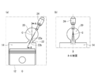
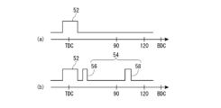
- FIG. 1 is a schematic diagram of a preferred embodiment of a diesel engine constructed in accordance with the present invention. The figure for demonstrating the fuel injected from the injector in the diesel engine shown in FIG. The figure which shows the injection timing of the injector in the diesel engine shown in FIG.
- FIG. 1 is a schematic view showing a cross section of a part of the configuration of a sub-chamber diesel engine 2 including a main combustion chamber and a sub combustion chamber that are connected to each other by a communication hole.
- the diesel engine 2 includes a cylinder block 4 and a cylinder head 6.
- a cylindrical cylinder 8 having an open end surface is formed, and in this cylinder 8, a piston 12 reciprocated by a crank 10 is arranged.
- the cylinder head 6 is mounted above the cylinder block 4, and the piston 12 is reciprocally moved in the vertical direction.
- a main combustion chamber 14 is defined inside the cylinder block 4 by the inner peripheral surface of the cylinder 8, the top surface of the piston 12, and the cylinder head 6.
- the cylinder head 6, when combined with the cylinder block 4, has an intake port (not shown) for sending fresh air into the main combustion chamber 14 and an exhaust port 16 for discharging the combustion gas generated in the combustion chamber. Are formed.
- a valve 18 At the outlet of the intake port (that is, the inlet to the main combustion chamber 14) and the inlet of the exhaust port 16 (that is, the outlet from the main combustion chamber 14), a valve 18 that opens and closes at a predetermined timing is provided.
- the cylinder head 6 is further provided with a sub combustion chamber 20 and a communication hole 22 communicating with the sub combustion chamber 20. Referring to FIGS. 2A and 2B together with FIG.
- the auxiliary combustion chamber 20 has a generally spherical shape, and the cylinder head 6 is combined with the cylinder block 4.
- the center c of the auxiliary combustion chamber 20 is eccentrically arranged with respect to the central axis o of the main combustion chamber 14.
- the communication hole 22 extends in a straight line with an upward inclination in the radial direction.
- the opening 22b of the communication hole 22, which is not the opening 22a formed in the auxiliary combustion chamber 20, is formed in the end surface of the cylinder head 6, and when the cylinder head 6 is combined with the cylinder block 4, the opening 22b is mainly formed.
- the auxiliary combustion chamber 20 and the main combustion chamber 14 are communicated with each other through the communication hole 22 so as to face the radial middle portion on the upper surface of the combustion chamber 14.
- the cylinder head 6 is further provided with an injector 24 for injecting fuel into the auxiliary combustion chamber 20.
- the injector 24 is a so-called in-valve injector, is generally in the shape of a shaft, and has a fuel passage (not shown) extending in the axial direction formed therein.
- An injector hole 26 for injecting fuel from the fuel flow path is provided on one axial end surface (lower end surface in the illustrated embodiment) of the injector 24, and at the other axial end portion (in the illustrated embodiment, in the illustrated embodiment).
- a needle valve (not shown) is built in the injector 24.
- the operation of the needle valve is controlled by an electromagnetic solenoid (not shown), and a desired injection is performed based on an electric signal sent from an engine ECU described later.
- the injection hole 26 is opened and closed at a certain time.
- the fuel injection timing from the injector 24 will be described later.
- the injector 24 is controlled by the control means described later so that the fuel injection pressure is 8 to 40 MPa. Since the diesel engine according to the present invention uses the sub-chamber type, it is not necessary to inject fuel at a high pressure (for example, 200 MPa) as in the direct injection type. Therefore, it is not necessary to make the structures of the injector, the fuel pump (not shown), the fuel passage pipe (to be described later), and the fuel pipe (not shown) excessively robust, and the manufacturing cost of the injector can be kept low.
- the injector 24 is inserted into the cylinder head 6, the injection hole 26 is exposed inside the auxiliary combustion chamber 20, and the other axial end of the injector 24 including at least the mouth 28 is exposed outside the cylinder head 6.
- a fuel passage pipe 30 fixed to the cylinder head 6 by a fixing means (not shown) is connected to the mouth portion 28.
- the axis of the injector 24 coincides with the axis of the communication hole 22.
- FIG. 1 and the like only one cylinder 8 is shown in the cylinder block 4, but in reality, a plurality of cylinders 8 are formed in the cylinder block 4, and the same number as the number of cylinders 8 is provided.
- a combustion chamber (main combustion chamber 14 and auxiliary combustion chamber 20) is present. That is, the same number of injectors 24 as the number of cylinders 8 are installed, and the fuel pressurized by the fuel pump (not shown) is distributed to the respective injectors 24 via the common fuel passage pipe 30.
- An exhaust passage 32 is connected to the exhaust port 16, and an oxidation catalyst 34 and a particulate collection filter 36 that purify exhaust exhausted from the combustion chamber are arranged in the exhaust passage 32.
- the oxidation catalyst 34 is provided on the upstream side of the exhaust passage 32 with respect to the particulate collection filter 36 (the flow of exhaust gas in the exhaust passage 32 is indicated by an arrow in FIG. 1), and the combustion gas exhausted from the combustion chamber Is sequentially discharged through the oxidation catalyst 34 and the particulate collection filter 36 and then discharged to the outside.
- the oxidation catalyst 34 can raise the temperature of the combustion gas by being activated by a predetermined oxidation reaction.
- the fine particle collecting filter 36 collects fine particles such as soot contained in the combustion gas and prevents the fine particles from being discharged to the outside. Since the oxidation catalyst 34 and the particulate collection filter 36 are widely used as an exhaust gas treatment device of a diesel engine, detailed description thereof will be omitted.
- the diesel engine 2 includes engine operating state detecting means for detecting the engine operating state, and control means.
- the engine operating state detecting means includes a crank angle sensor 38 for detecting the angular position of the crank 10 for reciprocating the piston 12, a water temperature sensor 40 for detecting the temperature of the cooling water of the diesel engine 2, and a common fuel passage pipe 30.
- Fuel pressure sensor 42 for detecting the pressure of the fuel
- temperature sensor 44 for detecting the wall surface of the auxiliary combustion chamber 20
- first exhaust gas temperature sensor 45 provided at the inlet of the oxidation catalyst 34, oxidation catalyst 34
- a second exhaust gas temperature sensor 46 provided between the particulate collection filter 36 and the particulate collection filter 36, and a differential pressure measuring means for measuring the differential pressure across the particulate collection filter 36.
- the differential pressure measuring means is composed of two pressure sensors 48a and 48b installed before and after the particulate collection filter 36.
- the control means is constituted by an engine ECU 50 such as a computer, which has a central processing unit (CPU) for performing arithmetic processing according to a control program, a read-on memory (ROM) for storing the control program and the like, a detected value detected, It is provided with a readable / writable random access memory (RAM) for temporarily storing operation results and the like, an input interface, and an output interface (details are not shown).
- CPU central processing unit
- ROM read-on memory
- RAM readable / writable random access memory
- the injection timing of the injector 24 during one cycle will be described.
- the horizontal axis indicates the crank angle
- the vertical axis indicates the presence or absence of an electric signal input from the engine ECU 50 to the injector 24.
- Inject At normal times, that is, when not in a regeneration state described later, as shown in FIG. 3A, the engine ECU 50 causes the injector 24 to inject fuel near the top dead center (TDC) in the compression stroke of the piston 12
- TDC top dead center
- the engine ECU 50 appropriately injects fuel as pre-injection (so-called pilot injection or pre-injection) by the injector 24 before the injector 24 injects fuel near the top dead center in the compression stroke of the piston 12 as the main injection 52. It may be controlled to eject.
- the engine ECU 50 causes the injector 24 to perform the main injection 52 as shown in FIG. 3B.
- the additional injection 54 is controlled during the expansion stroke of the piston 12.
- the engine ECU 50 performs the additional injection 54 until the crank angle from the compression top dead center of the piston 12 reaches 120 degrees. Such control is generally referred to as a "regeneration mode".
- (1) the predetermined amount of fine particles are collected by the fine particle collection filter 36, and (2) the cooling water temperature is The operating conditions are that it is a predetermined value or more, (3) the exhaust gas temperature is a predetermined value or more, and (4) the wall surface temperature of the auxiliary combustion chamber 20 is a predetermined value or more.
- the additional injection 54 is an after-injection 56 that injects fuel when the piston 12 is near the compression top dead center in the expansion stroke of the piston 12, and a post that injects fuel after the piston 12 has a crank angle of 90 degrees.
- Injection 58 The after-injection 56 is intended to cause an oxidation reaction by injecting the fuel into the burned gas, thereby raising the temperature of the exhaust gas and heating and activating the oxidation catalyst 34 itself.
- the post-injection 58 the injected fuel does not burn in the auxiliary combustion chamber 20 and the main combustion chamber 14 but is left unburned and is discharged to the exhaust passage 32 through the exhaust port 16 and then reaches the oxidation catalyst 34.
- the purpose is to raise the temperature of the exhaust gas passing through the oxidation catalyst 34 by causing an oxidation reaction in the oxidation catalyst 34.
- the engine ECU 50 appropriately controls the injection amount and injection timing of the after injection 56 and the post injection 58 according to the operating state detected by the engine operating state detecting means. At this time, the engine ECU 50 does not necessarily need to inject both the after-injection 56 and the post-injection 58, and controls to inject only the after-injection 56 or the post-injection 58 according to the operating state of the engine. Sometimes.
- the injector 24 can inject fuel at an arbitrary timing by an electric signal from the engine ECU 50, and when a predetermined amount of fine particles are collected by the fine particle collection filter 36, the injector is injected. 24 performs additional injection 54 in the expansion stroke of the piston 12 after performing the main injection 52. The exhaust gas is heated by the additional injection 54, and the particulates collected by the particulate collection filter 36 are burned. That is, in the sub-chamber diesel engine of the present invention, the particulate collection is performed without providing a separate fuel supply means other than the injector 24 for injecting fuel into the sub-combustion chamber 20, and thus without complicating the fuel system.
- the filter 36 can be regenerated.
- the additional injection 54 is performed in the first half of the expansion stroke of the piston 12, the pressure difference between the auxiliary combustion chamber 20 and the main combustion chamber 14 is relatively large, so the combustion gas and the like in the auxiliary combustion chamber 20.
- the flow velocity of the gas is relatively high, and the fuel injected into the sub combustion chamber 20 is sent from the sub combustion chamber 20 to the main combustion chamber 14 along with the flow of the combustion gas or the like.
- the additional injection 54 is performed in the latter half of the expansion stroke of the piston 12, since the pressure difference between the auxiliary combustion chamber 20 and the main combustion chamber 14 is relatively small, the flow velocity of the gas is relatively small, and the auxiliary combustion The fuel injected into the chamber 20 may not be sufficiently flowed by the gas flow.
- the effect of the additional injection 54 (that is, the effect of the after injection 56 and the post injection 58) cannot be obtained even if the additional injection 54 is performed.
- the injector 54 since the axis of the injector 24 is aligned with the axis of the communication hole 22, even if the additional injection 54 is performed in the latter half of the expansion stroke of the piston 12, the injector 54 is added as the additional injection 54.
- the fuel injected from 24 can reach the main combustion chamber 14 without adhering to the wall surfaces of the auxiliary combustion chamber 20 and the communication hole 22. Therefore, the additional injection 54 reaches the main combustion chamber 14 regardless of the timing of the expansion stroke of the piston 12, and the effect of the additional injection 54 is reliably obtained.
- the engine ECU 50 stops the regeneration mode, and the injector 24 is injected with the fuel during normal operation as shown in FIG. 3A, for example. Control to
- the cylinder head is placed on the upper surface of the cylinder block and the piston reciprocates in the vertical direction.
- the cylinder head is placed on the lateral surface of the cylinder block.
- the piston may reciprocate in the lateral (horizontal) direction.
- the pressure sensors 48a and 48b are arranged before and after the particulate collection filter 36 as the front-back differential pressure sensor 48, but the pressure sensor 48b arranged at the outlet of the particulate collection filter 36 is omitted.
- the atmospheric pressure may be used instead.
Landscapes
- Engineering & Computer Science (AREA)
- Chemical & Material Sciences (AREA)
- Combustion & Propulsion (AREA)
- Mechanical Engineering (AREA)
- General Engineering & Computer Science (AREA)
- Materials Engineering (AREA)
- Health & Medical Sciences (AREA)
- Chemical Kinetics & Catalysis (AREA)
- Toxicology (AREA)
- Processes For Solid Components From Exhaust (AREA)
- Electrical Control Of Air Or Fuel Supplied To Internal-Combustion Engine (AREA)
- Combustion Methods Of Internal-Combustion Engines (AREA)
Priority Applications (2)
| Application Number | Priority Date | Filing Date | Title |
|---|---|---|---|
| US17/295,224 US20210388755A1 (en) | 2018-11-20 | 2019-10-24 | Pre-chamber type diesel engine |
| EP19886474.6A EP3885543A4 (de) | 2018-11-20 | 2019-10-24 | Dieselmotor mit vorkammer |
Applications Claiming Priority (2)
| Application Number | Priority Date | Filing Date | Title |
|---|---|---|---|
| JP2018217397A JP2020084845A (ja) | 2018-11-20 | 2018-11-20 | 副室式ディーゼル機関 |
| JP2018-217397 | 2018-11-20 |
Publications (1)
| Publication Number | Publication Date |
|---|---|
| WO2020105352A1 true WO2020105352A1 (ja) | 2020-05-28 |
Family
ID=70774088
Family Applications (1)
| Application Number | Title | Priority Date | Filing Date |
|---|---|---|---|
| PCT/JP2019/041620 Ceased WO2020105352A1 (ja) | 2018-11-20 | 2019-10-24 | 副室式ディーゼル機関 |
Country Status (4)
| Country | Link |
|---|---|
| US (1) | US20210388755A1 (de) |
| EP (1) | EP3885543A4 (de) |
| JP (1) | JP2020084845A (de) |
| WO (1) | WO2020105352A1 (de) |
Families Citing this family (1)
| Publication number | Priority date | Publication date | Assignee | Title |
|---|---|---|---|---|
| EP4325030A3 (de) * | 2020-11-30 | 2024-05-01 | Innio Jenbacher GmbH & Co OG | Brennkraftmaschine und verfahren zum betreiben einer solchen brennkraftmaschine |
Citations (10)
| Publication number | Priority date | Publication date | Assignee | Title |
|---|---|---|---|---|
| JPH03108812U (de) * | 1990-02-22 | 1991-11-08 | ||
| JPH0633815A (ja) | 1992-07-10 | 1994-02-08 | Mazda Motor Corp | 副室式ディーゼルエンジンの燃料噴射装置 |
| JPH0633816A (ja) | 1992-07-10 | 1994-02-08 | Mazda Motor Corp | 副室式ディーゼルエンジンの燃料噴射装置 |
| JPH09217624A (ja) * | 1996-02-09 | 1997-08-19 | Isuzu Ceramics Kenkyusho:Kk | 重油を燃料とするディーゼルエンジン |
| JP2000054841A (ja) * | 1998-08-07 | 2000-02-22 | Kubota Corp | うず燃焼室式ディーゼルエンジン |
| JP2003155917A (ja) * | 2001-11-20 | 2003-05-30 | Hino Motors Ltd | 排気浄化方法 |
| JP2006241978A (ja) * | 2005-02-28 | 2006-09-14 | Yanmar Co Ltd | パティキュレートフィルタ再生機能を有する排ガス浄化装置及びその排ガス浄化装置を備えた内燃機関並びにパティキュレートフィルタ再生方法 |
| JP2010180744A (ja) * | 2009-02-04 | 2010-08-19 | Ihi Corp | 渦流室式ディーゼルエンジン |
| JP2012012999A (ja) * | 2010-06-30 | 2012-01-19 | Mazda Motor Corp | ディーゼルエンジン |
| JP2017066870A (ja) | 2015-09-28 | 2017-04-06 | 株式会社クボタ | ディーゼルエンジン |
Family Cites Families (4)
| Publication number | Priority date | Publication date | Assignee | Title |
|---|---|---|---|---|
| JP2004060443A (ja) * | 2002-07-24 | 2004-02-26 | Mazda Motor Corp | エンジンの排気浄化装置 |
| ITTO20030987A1 (it) * | 2003-12-09 | 2005-06-10 | Fiat Ricerche | Metodo di controllo di un motore ad accensione spontanea provvisto di un impianto di iniezione a collettore comune durante la rigenerazione del filtro del particolato. |
| JP2007270705A (ja) * | 2006-03-31 | 2007-10-18 | Mazda Motor Corp | エンジンのegr装置 |
| JP6229542B2 (ja) * | 2014-02-28 | 2017-11-15 | マツダ株式会社 | 排気浄化触媒の劣化診断方法及び劣化診断装置 |
-
2018
- 2018-11-20 JP JP2018217397A patent/JP2020084845A/ja active Pending
-
2019
- 2019-10-24 US US17/295,224 patent/US20210388755A1/en not_active Abandoned
- 2019-10-24 EP EP19886474.6A patent/EP3885543A4/de not_active Withdrawn
- 2019-10-24 WO PCT/JP2019/041620 patent/WO2020105352A1/ja not_active Ceased
Patent Citations (10)
| Publication number | Priority date | Publication date | Assignee | Title |
|---|---|---|---|---|
| JPH03108812U (de) * | 1990-02-22 | 1991-11-08 | ||
| JPH0633815A (ja) | 1992-07-10 | 1994-02-08 | Mazda Motor Corp | 副室式ディーゼルエンジンの燃料噴射装置 |
| JPH0633816A (ja) | 1992-07-10 | 1994-02-08 | Mazda Motor Corp | 副室式ディーゼルエンジンの燃料噴射装置 |
| JPH09217624A (ja) * | 1996-02-09 | 1997-08-19 | Isuzu Ceramics Kenkyusho:Kk | 重油を燃料とするディーゼルエンジン |
| JP2000054841A (ja) * | 1998-08-07 | 2000-02-22 | Kubota Corp | うず燃焼室式ディーゼルエンジン |
| JP2003155917A (ja) * | 2001-11-20 | 2003-05-30 | Hino Motors Ltd | 排気浄化方法 |
| JP2006241978A (ja) * | 2005-02-28 | 2006-09-14 | Yanmar Co Ltd | パティキュレートフィルタ再生機能を有する排ガス浄化装置及びその排ガス浄化装置を備えた内燃機関並びにパティキュレートフィルタ再生方法 |
| JP2010180744A (ja) * | 2009-02-04 | 2010-08-19 | Ihi Corp | 渦流室式ディーゼルエンジン |
| JP2012012999A (ja) * | 2010-06-30 | 2012-01-19 | Mazda Motor Corp | ディーゼルエンジン |
| JP2017066870A (ja) | 2015-09-28 | 2017-04-06 | 株式会社クボタ | ディーゼルエンジン |
Non-Patent Citations (1)
| Title |
|---|
| See also references of EP3885543A4 |
Also Published As
| Publication number | Publication date |
|---|---|
| JP2020084845A (ja) | 2020-06-04 |
| US20210388755A1 (en) | 2021-12-16 |
| EP3885543A1 (de) | 2021-09-29 |
| EP3885543A4 (de) | 2022-08-17 |
Similar Documents
| Publication | Publication Date | Title |
|---|---|---|
| CN105587379B (zh) | 一种dpf再生装置及方法 | |
| CN101903626B (zh) | 用于将燃料喷射到压缩点火发动机中的方法和设备 | |
| KR20130023093A (ko) | Egr 벤츄리 디젤 분사 | |
| EP3070309B1 (de) | Vorrichtung zur steuerung der zufuhr von kondensiertem wasser für verbrennungsmotoren mit zylindereinspritzung | |
| JP5632223B2 (ja) | エンジン装置の排気ガス再循環システム | |
| WO2020105352A1 (ja) | 副室式ディーゼル機関 | |
| JP5304177B2 (ja) | 排気浄化装置 | |
| CN108397300B (zh) | 发动机系统及控制发动机系统的方法 | |
| JP2012197681A (ja) | エンジン装置の排気ガス再循環システム | |
| CN207554189U (zh) | 一种混合燃烧的双燃料发动机 | |
| JP5745934B2 (ja) | 燃料噴射制御装置 | |
| JP4438708B2 (ja) | エンジンの燃料噴射制御装置 | |
| JP2002371900A (ja) | 内燃機関における燃料噴射制御方法 | |
| JP4530069B2 (ja) | 燃料噴射制御装置 | |
| JP7087801B2 (ja) | 内燃機関の制御装置 | |
| JP7317170B2 (ja) | エンジン | |
| JP2013245646A (ja) | 内燃機関の制御装置 | |
| JP5170317B2 (ja) | 内燃機関の燃料噴射制御装置 | |
| JP7003675B2 (ja) | 排気ガス浄化装置 | |
| JP2006083834A (ja) | 筒内噴射式ガソリンエンジンの制御装置 | |
| JP2008014157A (ja) | ディーゼルエンジンの制御装置 | |
| JP6606931B2 (ja) | 内燃機関の排気後処理装置 | |
| US20220010721A1 (en) | Pre-chamber type diesel engine | |
| JP6395117B2 (ja) | エンジンの制御装置 | |
| JP6169427B2 (ja) | アフターターボキャタリストの異常検知方法 |
Legal Events
| Date | Code | Title | Description |
|---|---|---|---|
| 121 | Ep: the epo has been informed by wipo that ep was designated in this application |
Ref document number: 19886474 Country of ref document: EP Kind code of ref document: A1 |
|
| NENP | Non-entry into the national phase |
Ref country code: DE |
|
| ENP | Entry into the national phase |
Ref document number: 2019886474 Country of ref document: EP Effective date: 20210621 |