WO2020105455A1 - Dispositif de génération de flux d'air - Google Patents
Dispositif de génération de flux d'airInfo
- Publication number
- WO2020105455A1 WO2020105455A1 PCT/JP2019/043684 JP2019043684W WO2020105455A1 WO 2020105455 A1 WO2020105455 A1 WO 2020105455A1 JP 2019043684 W JP2019043684 W JP 2019043684W WO 2020105455 A1 WO2020105455 A1 WO 2020105455A1
- Authority
- WO
- WIPO (PCT)
- Prior art keywords
- air
- outlet
- airflow
- air flow
- duty ratio
- Prior art date
- Legal status (The legal status is an assumption and is not a legal conclusion. Google has not performed a legal analysis and makes no representation as to the accuracy of the status listed.)
- Ceased
Links
Images



Classifications
-
- B—PERFORMING OPERATIONS; TRANSPORTING
- B60—VEHICLES IN GENERAL
- B60H—ARRANGEMENTS OF HEATING, COOLING, VENTILATING OR OTHER AIR-TREATING DEVICES SPECIALLY ADAPTED FOR PASSENGER OR GOODS SPACES OF VEHICLES
- B60H1/00—Heating, cooling or ventilating devices
- B60H1/00642—Control systems or circuits; Control members or indication devices for heating, cooling or ventilating devices
- B60H1/00735—Control systems or circuits characterised by their input, i.e. by the detection, measurement or calculation of particular conditions, e.g. signal treatment, dynamic models
- B60H1/00742—Control systems or circuits characterised by their input, i.e. by the detection, measurement or calculation of particular conditions, e.g. signal treatment, dynamic models by detection of the vehicle occupants' presence; by detection of conditions relating to the body of occupants, e.g. using radiant heat detectors
-
- B—PERFORMING OPERATIONS; TRANSPORTING
- B60—VEHICLES IN GENERAL
- B60H—ARRANGEMENTS OF HEATING, COOLING, VENTILATING OR OTHER AIR-TREATING DEVICES SPECIALLY ADAPTED FOR PASSENGER OR GOODS SPACES OF VEHICLES
- B60H1/00—Heating, cooling or ventilating devices
- B60H1/00421—Driving arrangements for parts of a vehicle air-conditioning
- B60H1/00428—Driving arrangements for parts of a vehicle air-conditioning electric
-
- B—PERFORMING OPERATIONS; TRANSPORTING
- B60—VEHICLES IN GENERAL
- B60H—ARRANGEMENTS OF HEATING, COOLING, VENTILATING OR OTHER AIR-TREATING DEVICES SPECIALLY ADAPTED FOR PASSENGER OR GOODS SPACES OF VEHICLES
- B60H1/00—Heating, cooling or ventilating devices
- B60H1/00642—Control systems or circuits; Control members or indication devices for heating, cooling or ventilating devices
- B60H1/00814—Control systems or circuits characterised by their output, for controlling particular components of the heating, cooling or ventilating installation
- B60H1/00821—Control systems or circuits characterised by their output, for controlling particular components of the heating, cooling or ventilating installation the components being ventilating, air admitting or air distributing devices
- B60H1/00828—Ventilators, e.g. speed control
-
- B—PERFORMING OPERATIONS; TRANSPORTING
- B60—VEHICLES IN GENERAL
- B60H—ARRANGEMENTS OF HEATING, COOLING, VENTILATING OR OTHER AIR-TREATING DEVICES SPECIALLY ADAPTED FOR PASSENGER OR GOODS SPACES OF VEHICLES
- B60H1/00—Heating, cooling or ventilating devices
- B60H1/00642—Control systems or circuits; Control members or indication devices for heating, cooling or ventilating devices
- B60H1/00978—Control systems or circuits characterised by failure of detection or safety means; Diagnostic methods
Definitions
- the present disclosure relates to an airflow generation device.
- This air conditioner includes an awakening detection unit that detects the awakening degree of the vehicle driver, and an air conditioning unit that can blow out air-conditioning air that partially brings the vehicle interior space in which the vehicle driver is located into different thermal environment states. ing. Further, there is provided control means for driving and controlling the air conditioning means based on the detection signal of the awakening detection means so as to partially bring the interior space of the vehicle into different thermal environment states.
- the air conditioner described in Patent Document 1 blows air by alternately switching between a concentrated blowout state in which the blowout airflow of the conditioned air is concentrated near the central part of the chest of the occupant and a diffused blowout state in which it is diffused throughout the passenger compartment. It is like this. However, with such a method, it may not be possible to reach the occupant with a sufficient air flow.
- the present disclosure aims to allow more sufficient airflow to reach an occupant.
- an airflow generation device includes an airflow generation unit that generates an airflow, and an air outlet that blows out the airflow generated by the airflow generation unit toward an occupant in a vehicle cabin.
- the air flow is intermittently blown out from the outlet by controlling the duty ratio which is the ratio of the pulse width of the pulse voltage applied to the air flow generating section and the pulse period of the pulse voltage to the duct leading to And a control unit.
- the control unit controls the duty ratio, which is the ratio of the frequency of the pulsed voltage applied to the airflow generation unit and the pulse width of the pulse period of the pulsed voltage, and intermittently from the outlet. Since the airflow is blown out to the passenger, a sufficient airflow can reach the occupant.
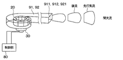
- FIG. 6 is a diagram showing a state in which a control unit controls an air flow blown from a face air outlet, a foot air outlet, and an air outlet to be an intermittent wind.
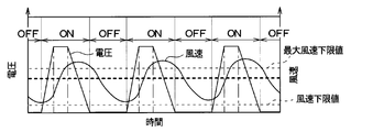
- 6 is a time chart of a pulsed voltage applied to a motor that rotates a fan and a wind speed of an air flow blown out from a face outlet. It is a figure showing the wind speed distribution of the comparative example which blows out continuous wind from an outlet. It is a figure showing the wind speed distribution of this air conditioner which blows out an intermittent wind from an outlet.
- the air conditioner 1 of the present embodiment is installed in a vehicle and sucks one or both of the inside air, which is the air inside the vehicle compartment, and the outside air, which is the air outside the vehicle compartment, and adjusts the temperature and humidity of the sucked air to adjust the temperature in the vehicle interior.
- the air inside the passenger compartment is conditioned by blowing it out to.
- the air conditioner 1 includes an air conditioning case 10, a fan 20, a motor 30, a motor holder 40, and the like.
- the fan 20 and the motor 30 correspond to an airflow generation unit.
- the air conditioning case 10 is made of resin that has some elasticity and is also excellent in strength. Examples of the resin forming the air conditioning case 10 include polypropylene.
- the air conditioning case 10 forms a ventilation path 11 through which air blown into the vehicle compartment flows.
- the air conditioning case 10 has an inside air introduction port 12 for introducing inside air into the ventilation passage 11 from a predetermined location in the vehicle interior at a portion upstream of the ventilation passage 11 in the air flow direction, and introduces outside air from outside the vehicle into the ventilation passage 11. It has an outside air introduction port 13 for.
- a duct (not shown) configured as a member different from the air conditioning case 10 may be connected to the inside air introduction port 12 or the outside air introduction port 13. In that case, air is introduced into the ventilation passage 11 from the inside air introduction port 12 or the outside air introduction port 13 via those ducts.
- the air conditioning case 10 has a plurality of blowout openings 14, 15, 16 for blowing air from the ventilation passage 11 into the vehicle interior on the downstream side of the ventilation passage 11 in the air flow direction.
- the air flowing through the ventilation path 11 of the air conditioning case 10 is blown into the vehicle compartment through the plurality of outlet openings 14, 15, 16.
- the plurality of blowout openings 14, 15, 16 are configured by a face blowout opening 14, a foot blowout opening 15, and a defroster blowout opening 16.
- the face blowout opening 14 blows out the conditioned air toward the upper body of the occupant seated in the front seat or its surroundings.
- the foot blowout opening 15 blows out the conditioned air toward the feet of the occupant.
- the defroster blowout opening 16 blows out the conditioned air toward the windshield of the vehicle.
- ducts configured as separate members from the air conditioning case 10 may be connected to each of the plurality of outlet openings 14, 15, and 16. In that case, air is blown into the vehicle compartment from the plurality of blowout openings 14, 15, 16 through these ducts.
- an inside / outside air switching door 17 Inside the air conditioning case 10, an inside / outside air switching door 17, a fan 20, an evaporator 50, a heater core 51, a temperature adjusting door 52, mode switching doors 53, 54, 55 and the like are provided.
- the inside / outside air switching door 17 continuously adjusts the opening area of the inside air inlet 12 and the opening area of the outside air inlet 13.
- the inside / outside air switching door 17 rotates so that the opening of one of the inside air introduction port 12 and the outside air introduction port 13 closes the other opening.
- the inside / outside air switching door 17 can adjust the air volume ratio of the inside air and the outside air introduced into the ventilation passage 11.
- a centrifugal fan is adopted as the fan 20 of this embodiment.
- the fan 20 generates a flow of air in the ventilation passage 11.
- the motor 30 that rotates the fan 20 is housed in a housing space 410 provided in a motor holder 40 that is fixed to the air conditioning case 10.
- the fan 20 is fixed to the rotating shaft of the motor 30.
- the fan 20 and the motor 30 constitute a blower.
- the evaporator 50 is a heat exchanger for cooling the air flowing through the ventilation passage 11.
- the evaporator 50 constitutes a well-known refrigeration cycle together with a compressor, a condenser, an expansion valve and the like (not shown).
- the evaporator 50 is arranged downstream of the expansion valve and upstream of the compressor in the refrigeration cycle.
- the evaporator 50 exchanges heat between the low-temperature low-pressure refrigerant flowing inside the tube (not shown) and the air passing through the evaporator 50, and cools the air passing through the evaporator 50 by the endothermic action of the latent heat of vaporization of the refrigerant. ..
- the heater core 51 is a heat exchanger for heating the air flowing through the ventilation passage 11.
- Engine cooling water flows inside a tube (not shown) of the heater core 51.
- the heater core 51 exchanges heat between the engine cooling water flowing inside the tube and the air passing through the heater core 51 to heat the air passing through the heater core 51.
- a temperature adjustment door 52 is provided between the evaporator 50 and the heater core 51.
- the temperature adjustment door 52 adjusts the ratio between the amount of air flow that bypasses the heater core 51 after passing through the evaporator 50 and the amount of air flow that passes through the heater core 51 after passing through the evaporator 50.
- the mode outlet doors 53, 54, 55 for adjusting the opening areas of the face outlet 14, the foot outlet 15, and the defroster outlet 16 are provided.
- the mode switching doors 53, 54, 55 are composed of a face door 53, a foot door 54 and a defroster door 55.
- the face door 53 opens and closes the face outlet 14.
- the foot door 54 opens and closes the foot outlet opening 15.
- the defroster door 55 opens and closes the defroster outlet opening 16.
- a duct 91 is connected to the face outlet 14 and the foot outlet 15.
- the face outlet 14 and the foot outlet 15 communicate with the face outlet 911 and the foot outlet 912 of the vehicle via the duct 91.
- a duct 92 is connected to the defroster outlet opening 16.
- the defroster outlet 16 is in communication with the defroster outlet 921 via a duct 92.
- the motor 30 for rotating the fan 20 of the air conditioner 1 of the present embodiment is controlled by the control unit 80 so that the airflows blown out from the face outlet 911 and the foot outlet 912 are intermittent winds. It
- the control unit 80 controls the voltage value, the frequency, and the duty ratio of the voltage of the motor 30 that rotates the fan 20 so that the airflows blown out from the face outlet 911 and the foot outlet 912 become an intermittent flow.
- the duty ratio is the ratio of the pulse width to the pulse period of the pulsed voltage applied to the motor 30 that rotates the fan 20.
- FIG. 3 is a time chart of the voltage waveform when the voltage applied to the motor 30 is turned on and off at a predetermined frequency and the wind speed of the air flow blown out from the face outlet 911.
- the voltage drops from the specified voltage to 0 volt.
- the rotation speed of the motor 30 that rotates the fan 20 becomes low, and the wind speed of the air flow blown out from the face outlet 911 also becomes slow.
- the wind speed is controlled to be equal to or higher than a predetermined wind speed lower limit value and lower than the maximum wind speed lower limit value. That is, before the rotation of the motor 30 that rotates the fan 20 stops, the voltage rises from 0 volt again.
- control unit 80 controls the voltage and duty ratio of the motor 30 that rotates the fan 20.
- the duty ratio is (ON period / ON period + OFF period) ⁇ 100 shown in FIG.
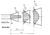
- FIG. 4 is a diagram showing a wind speed distribution of a comparative example in which continuous air is blown from the air outlet Ol.
- FIG. 5 is a diagram showing the wind speed distribution when the intermittent air is blown out from the air outlet Ol as in the air conditioner of the present embodiment.
- the wind velocity distribution is shown at a position where the distance from the outlet port Ol is L 1 and the wind velocity distribution is shown at a position where the distance from the outlet port Ol is L 2 .
- the wind speed increases as the length of the arrow in the direction in which the air blows out from the air outlet Ol in FIGS. 4 to 5 increases.
- the air blown from the air outlet Ol diffuses and advances in a direction intersecting with the blowing direction due to the expansion of the vortex, and decelerates.
- the air blown from the air outlet Ol proceeds so that the expansion of the vortex is suppressed so that the air does not diffuse so much in the direction intersecting the blowing direction, and the decrease in the wind speed is suppressed.
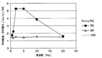
- FIG. 7 is a diagram showing experimental results showing the relationship between the average wind speed of the fan 20 at a certain point / the average power of the motor 30 that rotates the fan 20 and the frequency of the voltage of the motor 30 that rotates the fan 20.
- the vertical axis represents the average wind speed at a certain point when an intermittent wind is blown at a predetermined average power. It can be said that the larger the value on the vertical axis is, the better the intermittent wind has the higher wind speed.
- the duty ratio When the duty ratio is 80%, it is no different from when the duty ratio is 100%. Further, if the frequency of the voltage of the motor 30 that rotates the fan 20 is set to be higher than 20 hertz, it becomes the same as continuous air.
- the frequency of the voltage For example, by setting the frequency of the voltage to 2 to 5 hertz and the duty ratio to 50%, it is possible to blow out the intermittent wind by setting the voltage frequency and the duty ratio to appropriate conditions. .. It is preferable to set the frequency of the voltage to 0.5 hertz or more and less than 20 hertz.
- the duty ratio is configured to be selected in a range where intermittent wind is blown out.
- the duty ratio is selected to be 80% or less.
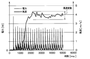
- FIG. 8 is a diagram showing changes over time in the electric power and the wind speed of the motor 30 that rotates the fan 20.
- FIG. 8 shows experimental data.
- the wind speed Immediately after the pulse voltage is applied to the motor 30 that rotates the fan 20, the wind speed does not increase immediately.
- the wind speed fluctuates within a predetermined wind speed range when some time passes after the pulsed voltage is applied to the motor 30.
- control unit 80 carries out the processing shown in FIG. Before the operation is started, no voltage is applied to the motor 30 that rotates the fan 20, and the fan 20 is not rotating. That is, there is no wind.
- the control unit 80 outputs a constant voltage to the motor 30 that rotates the fan 20 so that continuous air blows from the face outlet 911 for a predetermined period. Specifically, a constant voltage with a duty ratio of 100% is output to the motor 30.
- the control unit 80 periodically outputs a pulsed voltage to the motor 30 that rotates the fan 20 so that intermittent wind blows out from the face outlet 911 in S102.
- a pulsed voltage having a frequency of 10 Hz and a duty ratio of 50% is periodically output.
- the fan 20 blows out an intermittent wind.
- the motor 30 is controlled by the control unit 80 so that the wind speed of the intermittent wind blown out from the face outlet 911 falls within a predetermined wind speed fluctuation range.
- the airflow generation device of the present embodiment provides the airflow generation units 20 and 30 for generating the airflow and the airflow generated by the airflow generation units 20 and 30 to the interior of the vehicle cabin of the vehicle. It is provided with a duct 91 that leads to air outlets 911 and 912 that blow out toward the occupant. Furthermore, the duty ratio, which is the ratio of the frequency of the pulsed voltage applied to the airflow generation units 20 and 30 and the pulse width of the pulsed voltage, is controlled to intermittently flow the airflow from the air outlets 911 and 912. It is provided with a control unit 80 for blowing out.
- control unit 80 controls the frequency of the pulsed voltage applied to the air flow generation units 20 and 30 and the duty ratio, which is the ratio of the pulse width of the pulsed voltage to the pulse period, to control the blowing.
- the airflow is intermittently blown out from the outlets 911 and 912. Therefore, more sufficient airflow can reach the occupant.
- control unit 80 controls the frequency of the pulsed voltage between 0.5 hertz and 20 hertz. In this way, by controlling the frequency of the pulsed voltage between 0.5 hertz and 20 hertz, it is possible to intermittently blow out the air flow from the air outlets 911 and 912.
- control unit 80 controls the duty ratio within a range in which the airflow is intermittently blown out from the air outlets 911 and 912. In this way, the control unit 80 can control the duty ratio in the range in which the airflow is intermittently blown out from the air outlets 911 and 912.
- control unit 80 controls the frequency and duty ratio of the pulsed voltage applied to the air flow generation units 20 and 30 for a predetermined period after the operation is started, and continuously blows out the air flow from the air outlets 911 and 912. Let Then, after that, the frequency and duty ratio of the pulsed voltage applied to the air flow generation units 20 and 30 are controlled to intermittently blow out the air flow from the air outlets 911 and 912.
- the air flow can be quickly reached to the occupant, and then the sufficient air flow can be reached to the occupant.
- the pulsed predetermined voltage is periodically applied to the motor 30 so that the air flow is intermittently blown out from the face outlet 911, the foot outlet 912, and the defroster outlet 921 of the vehicle. did.
- shutters may be provided on the face outlet 14, the foot outlet 15, and the defroster outlet 16. Then, these shutters may be opened and closed to intermittently blow out the air flow from the face outlet 911, the foot outlet 912, and the defroster outlet 921 of the vehicle.
- the control unit 80 of the above-described embodiment controls both the frequency and the duty ratio of the pulsed voltage applied to the air flow generation units 20 and 30 to intermittently blow out the air flow from the air outlets 911 and 912. I was allowed to.
- control unit 80 controls at least one of the frequency and the duty ratio of the pulsed voltage applied to the air flow generation units 20 and 30 to intermittently blow out the air flow from the air outlets 911 and 912. You can
- the present disclosure is not limited to the above-described embodiments, and can be modified as appropriate. Further, the above embodiments are not unrelated to each other, and can be appropriately combined unless a combination is obviously impossible. Further, in each of the above-described embodiments, it goes without saying that the elements constituting the embodiment are not necessarily essential unless explicitly stated as being essential or in principle considered to be essential. Yes. Further, in each of the above-described embodiments, when numerical values such as the number of components of the embodiment, numerical values, amounts, ranges, etc. are referred to, it is clearly limited to a particular number and in principle limited to a specific number. The number is not limited to the specific number, except in the case of being performed.
- the airflow generating unit that generates the airflow and the airflow generated by the airflow generating unit are provided to the passenger in the vehicle cabin.
- the duty ratio which is the ratio of the pulse width of the pulse voltage applied to the air flow generation section and the pulse width of the pulse voltage applied to the air flow generation section, to the duct leading to the air outlet
- a control unit that blows out an air flow.
- control unit controls the frequency of the pulsed voltage between 0.5 hertz and 20 hertz. As described above, by controlling the frequency of the pulsed voltage between 0.5 hertz and 20 hertz, it is possible to intermittently blow out the air flow from the air outlet.
- control unit controls the duty ratio within a range in which the airflow is intermittently blown out from the air outlet. In this way, the control unit can control the duty ratio within the range in which the airflow is intermittently blown out from the blowout port.
- control unit controls the frequency and the duty ratio of the pulsed voltage applied to the air flow generation unit for a predetermined period after the operation is started to continuously generate the air flow from the air outlet. After being blown out, the frequency and duty ratio of the pulsed voltage applied to the airflow generating section are controlled to intermittently blow out the airflow from the air outlet.
- the air flow can be quickly reached to the occupant, and then the sufficient air flow can be reached to the occupant.
- the fan 20 and the motor 30 correspond to the airflow generation unit.
Landscapes
- Physics & Mathematics (AREA)
- Thermal Sciences (AREA)
- Engineering & Computer Science (AREA)
- Mechanical Engineering (AREA)
- Air-Conditioning For Vehicles (AREA)
Abstract
La présente invention concerne un dispositif de génération de flux d'air comprenant : une unité de génération de flux d'air (20, 30) qui génère un flux d'air ; un conduit (91) qui guide le flux d'air généré par l'unité de génération de flux d'air vers une sortie (911, 912) afin de souffler le flux d'air en direction des occupants dans l'habitacle d'un véhicule ; et une unité de commande (80) qui commande un rapport cyclique qui est le rapport entre la fréquence de la tension d'impulsion devant être appliquée à l'unité de génération de flux d'air et la largeur d'impulsion d'une période d'impulsion de la tension d'impulsion, et souffle par intermittence le flux d'air à partir de la sortie.
Priority Applications (2)
| Application Number | Priority Date | Filing Date | Title |
|---|---|---|---|
| CN201980075708.4A CN113056383A (zh) | 2018-11-19 | 2019-11-07 | 空气流产生装置 |
| US17/240,725 US20210245575A1 (en) | 2018-11-19 | 2021-04-26 | Airflow generating device |
Applications Claiming Priority (2)
| Application Number | Priority Date | Filing Date | Title |
|---|---|---|---|
| JP2018-216357 | 2018-11-19 | ||
| JP2018216357A JP2020082843A (ja) | 2018-11-19 | 2018-11-19 | 空気流発生装置 |
Related Child Applications (1)
| Application Number | Title | Priority Date | Filing Date |
|---|---|---|---|
| US17/240,725 Continuation US20210245575A1 (en) | 2018-11-19 | 2021-04-26 | Airflow generating device |
Publications (1)
| Publication Number | Publication Date |
|---|---|
| WO2020105455A1 true WO2020105455A1 (fr) | 2020-05-28 |
Family
ID=70774029
Family Applications (1)
| Application Number | Title | Priority Date | Filing Date |
|---|---|---|---|
| PCT/JP2019/043684 Ceased WO2020105455A1 (fr) | 2018-11-19 | 2019-11-07 | Dispositif de génération de flux d'air |
Country Status (4)
| Country | Link |
|---|---|
| US (1) | US20210245575A1 (fr) |
| JP (1) | JP2020082843A (fr) |
| CN (1) | CN113056383A (fr) |
| WO (1) | WO2020105455A1 (fr) |
Families Citing this family (1)
| Publication number | Priority date | Publication date | Assignee | Title |
|---|---|---|---|---|
| US12337654B2 (en) * | 2022-10-25 | 2025-06-24 | Ford Global Technologies, Llc | Air delivery system for a vehicle |
Citations (4)
| Publication number | Priority date | Publication date | Assignee | Title |
|---|---|---|---|---|
| JPS5623657A (en) * | 1979-07-31 | 1981-03-06 | Nissan Motor Co Ltd | Fan motor control system for air conditioner |
| JPS61226316A (ja) * | 1985-03-30 | 1986-10-08 | Nippon Denso Co Ltd | 車両空調装置 |
| JPH01178111U (fr) * | 1988-06-07 | 1989-12-20 | ||
| JP2007106337A (ja) * | 2005-10-17 | 2007-04-26 | Denso Corp | 居眠り防止装置 |
Family Cites Families (8)
| Publication number | Priority date | Publication date | Assignee | Title |
|---|---|---|---|---|
| US4555910A (en) * | 1984-01-23 | 1985-12-03 | Borg-Warner Corporation | Coolant/refrigerant temperature control system |
| JPH09173458A (ja) * | 1995-12-25 | 1997-07-08 | Matsushita Electric Works Ltd | 覚醒装置 |
| JP3959305B2 (ja) * | 2002-05-16 | 2007-08-15 | カルソニックカンセイ株式会社 | 車両用空調制御装置 |
| US7845391B2 (en) * | 2004-01-15 | 2010-12-07 | Mitsubishi Heavy Industries, Ltd. | Air-conditioning unit and vehicle air-conditioning apparatus |
| US8620521B2 (en) * | 2011-02-18 | 2013-12-31 | Honda Motor Co., Ltd. | Vehicle HVAC water splash prevention method and apparatus |
| JP5492857B2 (ja) * | 2011-10-25 | 2014-05-14 | カルソニックカンセイ株式会社 | 車両用空調制御装置 |
| JP6278214B2 (ja) * | 2015-12-22 | 2018-02-14 | トヨタ自動車株式会社 | 車両用空調装置 |
| US20180333667A1 (en) * | 2017-05-18 | 2018-11-22 | Ford Global Technologies, Llc | System and method for monitoring condition of cabin air filter |
-
2018
- 2018-11-19 JP JP2018216357A patent/JP2020082843A/ja active Pending
-
2019
- 2019-11-07 CN CN201980075708.4A patent/CN113056383A/zh not_active Withdrawn
- 2019-11-07 WO PCT/JP2019/043684 patent/WO2020105455A1/fr not_active Ceased
-
2021
- 2021-04-26 US US17/240,725 patent/US20210245575A1/en not_active Abandoned
Patent Citations (4)
| Publication number | Priority date | Publication date | Assignee | Title |
|---|---|---|---|---|
| JPS5623657A (en) * | 1979-07-31 | 1981-03-06 | Nissan Motor Co Ltd | Fan motor control system for air conditioner |
| JPS61226316A (ja) * | 1985-03-30 | 1986-10-08 | Nippon Denso Co Ltd | 車両空調装置 |
| JPH01178111U (fr) * | 1988-06-07 | 1989-12-20 | ||
| JP2007106337A (ja) * | 2005-10-17 | 2007-04-26 | Denso Corp | 居眠り防止装置 |
Also Published As
| Publication number | Publication date |
|---|---|
| US20210245575A1 (en) | 2021-08-12 |
| JP2020082843A (ja) | 2020-06-04 |
| CN113056383A (zh) | 2021-06-29 |
Similar Documents
| Publication | Publication Date | Title |
|---|---|---|
| JP5556619B2 (ja) | 車両用空調装置 | |
| EP2123495A1 (fr) | Registre, climatiseur individuel et climatiseur pour véhicule | |
| JP5724827B2 (ja) | 空力音低減装置 | |
| WO2012144153A1 (fr) | Dispositif de climatisation pour un véhicule | |
| US20210245575A1 (en) | Airflow generating device | |
| JP2000127740A (ja) | 遠心送風機 | |
| JP5924230B2 (ja) | 空調装置 | |
| JP5640928B2 (ja) | 空力音低減装置 | |
| JP5640902B2 (ja) | 空力騒音低減装置 | |
| JP6844356B2 (ja) | 車両用空調装置 | |
| JPH04146813A (ja) | 空調装置の空調風吹出装置 | |
| JP2002036850A (ja) | 車両用空調装置の送風ユニット | |
| JP3915259B2 (ja) | 車両用空調装置 | |
| JP5098940B2 (ja) | 車両用空調装置 | |
| JP2005059654A (ja) | 車両用空調装置 | |
| JP2009166828A (ja) | 車両用空調装置 | |
| JPH0558148A (ja) | 自動車用空調装置 | |
| JP2876778B2 (ja) | 車両用空調装置 | |
| JP2000071745A (ja) | 車両用空調装置 | |
| JPH0672141A (ja) | 車両用空気調和装置 | |
| JP5955158B2 (ja) | 車両用空調システム | |
| JPH07186688A (ja) | 車両用空調装置 | |
| JP2013199248A (ja) | 車両用空気調和装置 | |
| JP2006038431A (ja) | 空調装置 | |
| KR100665556B1 (ko) | 차량용 공기조화장치의 케이스 |
Legal Events
| Date | Code | Title | Description |
|---|---|---|---|
| 121 | Ep: the epo has been informed by wipo that ep was designated in this application |
Ref document number: 19887555 Country of ref document: EP Kind code of ref document: A1 |
|
| NENP | Non-entry into the national phase |
Ref country code: DE |
|
| 122 | Ep: pct application non-entry in european phase |
Ref document number: 19887555 Country of ref document: EP Kind code of ref document: A1 |