WO2020105460A1 - 機械発泡用硬化性組成物およびその発泡体の製造方法 - Google Patents
機械発泡用硬化性組成物およびその発泡体の製造方法Info
- Publication number
- WO2020105460A1 WO2020105460A1 PCT/JP2019/043738 JP2019043738W WO2020105460A1 WO 2020105460 A1 WO2020105460 A1 WO 2020105460A1 JP 2019043738 W JP2019043738 W JP 2019043738W WO 2020105460 A1 WO2020105460 A1 WO 2020105460A1
- Authority
- WO
- WIPO (PCT)
- Prior art keywords
- gear pump
- mechanical foaming
- pressure
- curable composition
- discharge
- Prior art date
- Legal status (The legal status is an assumption and is not a legal conclusion. Google has not performed a legal analysis and makes no representation as to the accuracy of the status listed.)
- Ceased
Links
Images





Classifications
-
- B—PERFORMING OPERATIONS; TRANSPORTING
- B29—WORKING OF PLASTICS; WORKING OF SUBSTANCES IN A PLASTIC STATE IN GENERAL
- B29C—SHAPING OR JOINING OF PLASTICS; SHAPING OF MATERIAL IN A PLASTIC STATE, NOT OTHERWISE PROVIDED FOR; AFTER-TREATMENT OF THE SHAPED PRODUCTS, e.g. REPAIRING
- B29C44/00—Shaping by internal pressure generated in the material, e.g. swelling or foaming ; Producing porous or cellular expanded plastics articles
- B29C44/02—Shaping by internal pressure generated in the material, e.g. swelling or foaming ; Producing porous or cellular expanded plastics articles for articles of definite length, i.e. discrete articles
- B29C44/04—Shaping by internal pressure generated in the material, e.g. swelling or foaming ; Producing porous or cellular expanded plastics articles for articles of definite length, i.e. discrete articles consisting of at least two parts of chemically or physically different materials, e.g. having different densities
- B29C44/0492—Devices for feeding the different materials
-
- B—PERFORMING OPERATIONS; TRANSPORTING
- B05—SPRAYING OR ATOMISING IN GENERAL; APPLYING FLUENT MATERIALS TO SURFACES, IN GENERAL
- B05B—SPRAYING APPARATUS; ATOMISING APPARATUS; NOZZLES
- B05B1/00—Nozzles, spray heads or other outlets, with or without auxiliary devices such as valves, heating means
- B05B1/30—Nozzles, spray heads or other outlets, with or without auxiliary devices such as valves, heating means designed to control volume of flow, e.g. with adjustable passages
- B05B1/3033—Nozzles, spray heads or other outlets, with or without auxiliary devices such as valves, heating means designed to control volume of flow, e.g. with adjustable passages the control being effected by relative coaxial longitudinal movement of the controlling element and the spray head
- B05B1/304—Nozzles, spray heads or other outlets, with or without auxiliary devices such as valves, heating means designed to control volume of flow, e.g. with adjustable passages the control being effected by relative coaxial longitudinal movement of the controlling element and the spray head the controlling element being a lift valve
- B05B1/3046—Nozzles, spray heads or other outlets, with or without auxiliary devices such as valves, heating means designed to control volume of flow, e.g. with adjustable passages the control being effected by relative coaxial longitudinal movement of the controlling element and the spray head the controlling element being a lift valve the valve element, e.g. a needle, co-operating with a valve seat located downstream of the valve element and its actuating means, generally in the proximity of the outlet orifice
-
- B—PERFORMING OPERATIONS; TRANSPORTING
- B05—SPRAYING OR ATOMISING IN GENERAL; APPLYING FLUENT MATERIALS TO SURFACES, IN GENERAL
- B05B—SPRAYING APPARATUS; ATOMISING APPARATUS; NOZZLES
- B05B12/00—Arrangements for controlling delivery; Arrangements for controlling the spray area
- B05B12/004—Arrangements for controlling delivery; Arrangements for controlling the spray area comprising sensors for monitoring the delivery, e.g. by displaying the sensed value or generating an alarm
- B05B12/006—Pressure or flow rate sensors
- B05B12/008—Pressure or flow rate sensors integrated in or attached to a discharge apparatus, e.g. a spray gun
-
- B—PERFORMING OPERATIONS; TRANSPORTING
- B05—SPRAYING OR ATOMISING IN GENERAL; APPLYING FLUENT MATERIALS TO SURFACES, IN GENERAL
- B05B—SPRAYING APPARATUS; ATOMISING APPARATUS; NOZZLES
- B05B7/00—Spraying apparatus for discharge of liquids or other fluent materials from two or more sources, e.g. of liquid and air, of powder and gas
- B05B7/0018—Spraying apparatus for discharge of liquids or other fluent materials from two or more sources, e.g. of liquid and air, of powder and gas with devices for making foam
- B05B7/0025—Spraying apparatus for discharge of liquids or other fluent materials from two or more sources, e.g. of liquid and air, of powder and gas with devices for making foam with a compressed gas supply
- B05B7/0031—Spraying apparatus for discharge of liquids or other fluent materials from two or more sources, e.g. of liquid and air, of powder and gas with devices for making foam with a compressed gas supply with disturbing means promoting mixing, e.g. balls, crowns
- B05B7/0043—Spraying apparatus for discharge of liquids or other fluent materials from two or more sources, e.g. of liquid and air, of powder and gas with devices for making foam with a compressed gas supply with disturbing means promoting mixing, e.g. balls, crowns including a plurality of individual elements, e.g. needles, baffles, rotatable blades
-
- B—PERFORMING OPERATIONS; TRANSPORTING
- B05—SPRAYING OR ATOMISING IN GENERAL; APPLYING FLUENT MATERIALS TO SURFACES, IN GENERAL
- B05B—SPRAYING APPARATUS; ATOMISING APPARATUS; NOZZLES
- B05B7/00—Spraying apparatus for discharge of liquids or other fluent materials from two or more sources, e.g. of liquid and air, of powder and gas
- B05B7/02—Spray pistols; Apparatus for discharge
- B05B7/04—Spray pistols; Apparatus for discharge with arrangements for mixing liquids or other fluent materials before discharge
- B05B7/0416—Spray pistols; Apparatus for discharge with arrangements for mixing liquids or other fluent materials before discharge with arrangements for mixing one gas and one liquid
- B05B7/0483—Spray pistols; Apparatus for discharge with arrangements for mixing liquids or other fluent materials before discharge with arrangements for mixing one gas and one liquid with gas and liquid jets intersecting in the mixing chamber
-
- B—PERFORMING OPERATIONS; TRANSPORTING
- B05—SPRAYING OR ATOMISING IN GENERAL; APPLYING FLUENT MATERIALS TO SURFACES, IN GENERAL
- B05B—SPRAYING APPARATUS; ATOMISING APPARATUS; NOZZLES
- B05B7/00—Spraying apparatus for discharge of liquids or other fluent materials from two or more sources, e.g. of liquid and air, of powder and gas
- B05B7/02—Spray pistols; Apparatus for discharge
- B05B7/12—Spray pistols; Apparatus for discharge designed to control volume of flow, e.g. with adjustable passages
- B05B7/1254—Spray pistols; Apparatus for discharge designed to control volume of flow, e.g. with adjustable passages the controlling means being fluid actuated
- B05B7/1263—Spray pistols; Apparatus for discharge designed to control volume of flow, e.g. with adjustable passages the controlling means being fluid actuated pneumatically actuated
-
- B—PERFORMING OPERATIONS; TRANSPORTING
- B05—SPRAYING OR ATOMISING IN GENERAL; APPLYING FLUENT MATERIALS TO SURFACES, IN GENERAL
- B05B—SPRAYING APPARATUS; ATOMISING APPARATUS; NOZZLES
- B05B7/00—Spraying apparatus for discharge of liquids or other fluent materials from two or more sources, e.g. of liquid and air, of powder and gas
- B05B7/24—Spraying apparatus for discharge of liquids or other fluent materials from two or more sources, e.g. of liquid and air, of powder and gas with means, e.g. a container, for supplying liquid or other fluent material to a discharge device
- B05B7/26—Apparatus in which liquids or other fluent materials from different sources are brought together before entering the discharge device
- B05B7/262—Apparatus in which liquids or other fluent materials from different sources are brought together before entering the discharge device a liquid and a gas being brought together before entering the discharge device
- B05B7/267—Apparatus in which liquids or other fluent materials from different sources are brought together before entering the discharge device a liquid and a gas being brought together before entering the discharge device the liquid and the gas being both under pressure
-
- B—PERFORMING OPERATIONS; TRANSPORTING
- B29—WORKING OF PLASTICS; WORKING OF SUBSTANCES IN A PLASTIC STATE IN GENERAL
- B29B—PREPARATION OR PRETREATMENT OF THE MATERIAL TO BE SHAPED; MAKING GRANULES OR PREFORMS; RECOVERY OF PLASTICS OR OTHER CONSTITUENTS OF WASTE MATERIAL CONTAINING PLASTICS
- B29B7/00—Mixing; Kneading
- B29B7/002—Methods
- B29B7/007—Methods for continuous mixing
-
- B—PERFORMING OPERATIONS; TRANSPORTING
- B29—WORKING OF PLASTICS; WORKING OF SUBSTANCES IN A PLASTIC STATE IN GENERAL
- B29B—PREPARATION OR PRETREATMENT OF THE MATERIAL TO BE SHAPED; MAKING GRANULES OR PREFORMS; RECOVERY OF PLASTICS OR OTHER CONSTITUENTS OF WASTE MATERIAL CONTAINING PLASTICS
- B29B7/00—Mixing; Kneading
- B29B7/30—Mixing; Kneading continuous, with mechanical mixing or kneading devices
- B29B7/58—Component parts, details or accessories; Auxiliary operations
- B29B7/72—Measuring, controlling or regulating
- B29B7/726—Measuring properties of mixture, e.g. temperature or density
-
- B—PERFORMING OPERATIONS; TRANSPORTING
- B29—WORKING OF PLASTICS; WORKING OF SUBSTANCES IN A PLASTIC STATE IN GENERAL
- B29B—PREPARATION OR PRETREATMENT OF THE MATERIAL TO BE SHAPED; MAKING GRANULES OR PREFORMS; RECOVERY OF PLASTICS OR OTHER CONSTITUENTS OF WASTE MATERIAL CONTAINING PLASTICS
- B29B7/00—Mixing; Kneading
- B29B7/74—Mixing; Kneading using other mixers or combinations of mixers, e.g. of dissimilar mixers ; Plant
- B29B7/7404—Mixing devices specially adapted for foamable substances
- B29B7/7409—Mixing devices specially adapted for foamable substances with supply of gas
- B29B7/7414—Mixing devices specially adapted for foamable substances with supply of gas with rotatable stirrer, e.g. using an intermeshing rotor-stator system
-
- B—PERFORMING OPERATIONS; TRANSPORTING
- B29—WORKING OF PLASTICS; WORKING OF SUBSTANCES IN A PLASTIC STATE IN GENERAL
- B29B—PREPARATION OR PRETREATMENT OF THE MATERIAL TO BE SHAPED; MAKING GRANULES OR PREFORMS; RECOVERY OF PLASTICS OR OTHER CONSTITUENTS OF WASTE MATERIAL CONTAINING PLASTICS
- B29B7/00—Mixing; Kneading
- B29B7/74—Mixing; Kneading using other mixers or combinations of mixers, e.g. of dissimilar mixers ; Plant
- B29B7/7461—Combinations of dissimilar mixers
-
- B—PERFORMING OPERATIONS; TRANSPORTING
- B29—WORKING OF PLASTICS; WORKING OF SUBSTANCES IN A PLASTIC STATE IN GENERAL
- B29B—PREPARATION OR PRETREATMENT OF THE MATERIAL TO BE SHAPED; MAKING GRANULES OR PREFORMS; RECOVERY OF PLASTICS OR OTHER CONSTITUENTS OF WASTE MATERIAL CONTAINING PLASTICS
- B29B7/00—Mixing; Kneading
- B29B7/74—Mixing; Kneading using other mixers or combinations of mixers, e.g. of dissimilar mixers ; Plant
- B29B7/7476—Systems, i.e. flow charts or diagrams; Plants
- B29B7/748—Plants
-
- B—PERFORMING OPERATIONS; TRANSPORTING
- B29—WORKING OF PLASTICS; WORKING OF SUBSTANCES IN A PLASTIC STATE IN GENERAL
- B29B—PREPARATION OR PRETREATMENT OF THE MATERIAL TO BE SHAPED; MAKING GRANULES OR PREFORMS; RECOVERY OF PLASTICS OR OTHER CONSTITUENTS OF WASTE MATERIAL CONTAINING PLASTICS
- B29B7/00—Mixing; Kneading
- B29B7/80—Component parts, details or accessories; Auxiliary operations
- B29B7/88—Adding charges, i.e. additives
- B29B7/90—Fillers or reinforcements, e.g. fibres
-
- B—PERFORMING OPERATIONS; TRANSPORTING
- B29—WORKING OF PLASTICS; WORKING OF SUBSTANCES IN A PLASTIC STATE IN GENERAL
- B29C—SHAPING OR JOINING OF PLASTICS; SHAPING OF MATERIAL IN A PLASTIC STATE, NOT OTHERWISE PROVIDED FOR; AFTER-TREATMENT OF THE SHAPED PRODUCTS, e.g. REPAIRING
- B29C44/00—Shaping by internal pressure generated in the material, e.g. swelling or foaming ; Producing porous or cellular expanded plastics articles
- B29C44/34—Auxiliary operations
- B29C44/3442—Mixing, kneading or conveying the foamable material
-
- B—PERFORMING OPERATIONS; TRANSPORTING
- B29—WORKING OF PLASTICS; WORKING OF SUBSTANCES IN A PLASTIC STATE IN GENERAL
- B29C—SHAPING OR JOINING OF PLASTICS; SHAPING OF MATERIAL IN A PLASTIC STATE, NOT OTHERWISE PROVIDED FOR; AFTER-TREATMENT OF THE SHAPED PRODUCTS, e.g. REPAIRING
- B29C44/00—Shaping by internal pressure generated in the material, e.g. swelling or foaming ; Producing porous or cellular expanded plastics articles
- B29C44/34—Auxiliary operations
- B29C44/3442—Mixing, kneading or conveying the foamable material
- B29C44/3446—Feeding the blowing agent
-
- B—PERFORMING OPERATIONS; TRANSPORTING
- B29—WORKING OF PLASTICS; WORKING OF SUBSTANCES IN A PLASTIC STATE IN GENERAL
- B29C—SHAPING OR JOINING OF PLASTICS; SHAPING OF MATERIAL IN A PLASTIC STATE, NOT OTHERWISE PROVIDED FOR; AFTER-TREATMENT OF THE SHAPED PRODUCTS, e.g. REPAIRING
- B29C44/00—Shaping by internal pressure generated in the material, e.g. swelling or foaming ; Producing porous or cellular expanded plastics articles
- B29C44/34—Auxiliary operations
- B29C44/35—Component parts; Details or accessories
- B29C44/355—Characteristics of the foam, e.g. having particular surface properties or structure
-
- B—PERFORMING OPERATIONS; TRANSPORTING
- B29—WORKING OF PLASTICS; WORKING OF SUBSTANCES IN A PLASTIC STATE IN GENERAL
- B29C—SHAPING OR JOINING OF PLASTICS; SHAPING OF MATERIAL IN A PLASTIC STATE, NOT OTHERWISE PROVIDED FOR; AFTER-TREATMENT OF THE SHAPED PRODUCTS, e.g. REPAIRING
- B29C44/00—Shaping by internal pressure generated in the material, e.g. swelling or foaming ; Producing porous or cellular expanded plastics articles
- B29C44/34—Auxiliary operations
- B29C44/60—Measuring, controlling or regulating
-
- C—CHEMISTRY; METALLURGY
- C08—ORGANIC MACROMOLECULAR COMPOUNDS; THEIR PREPARATION OR CHEMICAL WORKING-UP; COMPOSITIONS BASED THEREON
- C08J—WORKING-UP; GENERAL PROCESSES OF COMPOUNDING; AFTER-TREATMENT NOT COVERED BY SUBCLASSES C08B, C08C, C08F, C08G or C08H
- C08J9/00—Working-up of macromolecular substances to porous or cellular articles or materials; After-treatment thereof
- C08J9/30—Working-up of macromolecular substances to porous or cellular articles or materials; After-treatment thereof by mixing gases into liquid compositions or plastisols, e.g. frothing with air
-
- B—PERFORMING OPERATIONS; TRANSPORTING
- B05—SPRAYING OR ATOMISING IN GENERAL; APPLYING FLUENT MATERIALS TO SURFACES, IN GENERAL
- B05B—SPRAYING APPARATUS; ATOMISING APPARATUS; NOZZLES
- B05B7/00—Spraying apparatus for discharge of liquids or other fluent materials from two or more sources, e.g. of liquid and air, of powder and gas
- B05B7/16—Spraying apparatus for discharge of liquids or other fluent materials from two or more sources, e.g. of liquid and air, of powder and gas incorporating means for heating or cooling the material to be sprayed
-
- B—PERFORMING OPERATIONS; TRANSPORTING
- B05—SPRAYING OR ATOMISING IN GENERAL; APPLYING FLUENT MATERIALS TO SURFACES, IN GENERAL
- B05D—PROCESSES FOR APPLYING FLUENT MATERIALS TO SURFACES, IN GENERAL
- B05D1/00—Processes for applying liquids or other fluent materials
- B05D1/26—Processes for applying liquids or other fluent materials performed by applying the liquid or other fluent material from an outlet device in contact with, or almost in contact with, the surface
-
- B—PERFORMING OPERATIONS; TRANSPORTING
- B29—WORKING OF PLASTICS; WORKING OF SUBSTANCES IN A PLASTIC STATE IN GENERAL
- B29K—INDEXING SCHEME ASSOCIATED WITH SUBCLASSES B29B, B29C OR B29D, RELATING TO MOULDING MATERIALS OR TO MATERIALS FOR MOULDS, REINFORCEMENTS, FILLERS OR PREFORMED PARTS, e.g. INSERTS
- B29K2075/00—Use of PU, i.e. polyureas or polyurethanes or derivatives thereof, as moulding material
-
- B—PERFORMING OPERATIONS; TRANSPORTING
- B29—WORKING OF PLASTICS; WORKING OF SUBSTANCES IN A PLASTIC STATE IN GENERAL
- B29K—INDEXING SCHEME ASSOCIATED WITH SUBCLASSES B29B, B29C OR B29D, RELATING TO MOULDING MATERIALS OR TO MATERIALS FOR MOULDS, REINFORCEMENTS, FILLERS OR PREFORMED PARTS, e.g. INSERTS
- B29K2105/00—Condition, form or state of moulded material or of the material to be shaped
- B29K2105/0058—Liquid or visquous
-
- C—CHEMISTRY; METALLURGY
- C08—ORGANIC MACROMOLECULAR COMPOUNDS; THEIR PREPARATION OR CHEMICAL WORKING-UP; COMPOSITIONS BASED THEREON
- C08J—WORKING-UP; GENERAL PROCESSES OF COMPOUNDING; AFTER-TREATMENT NOT COVERED BY SUBCLASSES C08B, C08C, C08F, C08G or C08H
- C08J2201/00—Foams characterised by the foaming process
- C08J2201/02—Foams characterised by the foaming process characterised by mechanical pre- or post-treatments
- C08J2201/026—Crosslinking before of after foaming
-
- C—CHEMISTRY; METALLURGY
- C08—ORGANIC MACROMOLECULAR COMPOUNDS; THEIR PREPARATION OR CHEMICAL WORKING-UP; COMPOSITIONS BASED THEREON
- C08J—WORKING-UP; GENERAL PROCESSES OF COMPOUNDING; AFTER-TREATMENT NOT COVERED BY SUBCLASSES C08B, C08C, C08F, C08G or C08H
- C08J2323/00—Characterised by the use of homopolymers or copolymers of unsaturated aliphatic hydrocarbons having only one carbon-to-carbon double bond; Derivatives of such polymers
- C08J2323/02—Characterised by the use of homopolymers or copolymers of unsaturated aliphatic hydrocarbons having only one carbon-to-carbon double bond; Derivatives of such polymers not modified by chemical after treatment
-
- C—CHEMISTRY; METALLURGY
- C08—ORGANIC MACROMOLECULAR COMPOUNDS; THEIR PREPARATION OR CHEMICAL WORKING-UP; COMPOSITIONS BASED THEREON
- C08J—WORKING-UP; GENERAL PROCESSES OF COMPOUNDING; AFTER-TREATMENT NOT COVERED BY SUBCLASSES C08B, C08C, C08F, C08G or C08H
- C08J2333/00—Characterised by the use of homopolymers or copolymers of compounds having one or more unsaturated aliphatic radicals, each having only one carbon-to-carbon double bond, and only one being terminated by only one carboxyl radical, or of salts, anhydrides, esters, amides, imides, or nitriles thereof; Derivatives of such polymers
- C08J2333/04—Characterised by the use of homopolymers or copolymers of compounds having one or more unsaturated aliphatic radicals, each having only one carbon-to-carbon double bond, and only one being terminated by only one carboxyl radical, or of salts, anhydrides, esters, amides, imides, or nitriles thereof; Derivatives of such polymers esters
-
- C—CHEMISTRY; METALLURGY
- C08—ORGANIC MACROMOLECULAR COMPOUNDS; THEIR PREPARATION OR CHEMICAL WORKING-UP; COMPOSITIONS BASED THEREON
- C08J—WORKING-UP; GENERAL PROCESSES OF COMPOUNDING; AFTER-TREATMENT NOT COVERED BY SUBCLASSES C08B, C08C, C08F, C08G or C08H
- C08J2383/00—Characterised by the use of macromolecular compounds obtained by reactions forming in the main chain of the macromolecule a linkage containing silicon with or without sulfur, nitrogen, oxygen, or carbon only; Derivatives of such polymers
- C08J2383/04—Polysiloxanes
Definitions
- the present invention relates to a curable composition suitable for mechanical foaming and a method for producing the foam. More specifically, the present invention relates to a curable composition suitable for mechanical foaming using a gear pump type mechanical foaming device, and a method for producing a foam thereof.
- foams made by foaming a foamable material containing a liquid resin and curing or solidifying it have been used.
- Known methods for producing a foam include chemical foaming in which two liquids of a main agent and a curing agent are mixed to chemically foam, and mechanical foaming in which a gas is mechanically mixed into a one-liquid liquid. ing.
- the mechanical foaming device is mainly of a plunger pump type and a gear pump type. Since the gear pump type can quantitatively deliver the liquid, it is easier to control the expansion ratio than the plunger pump type.
- the one-pack type curable resin material is selected from the viewpoint of containing a resin component capable of mechanical foaming using a plunger pump type mechanical foaming device.
- the one-pack type curable resin material changes according to various requirements whether or not it can be foamed. The requirements are that the type of resin component such as (meth) acrylic resin, epoxy resin, urethane resin, silicone resin, thermoplastic resin, etc., as well as the viscosity, thixotropy, cured form, etc. of the material containing the resin component are different.
- the present invention has been made in view of the above situation, and when mechanically foaming, the foam is uniformly dispersed, and the foam does not float on the liquid surface, and a machine capable of forming a foam well. It is intended to provide a curable composition for foaming.
- the bubbles when mechanically foaming using a mechanical foaming device, the bubbles are uniformly dispersed, the foaming state is good without the bubbles rising to the liquid surface, and the foaming state is uniform from the appearance. It is an object of the present invention to provide a method for producing a foam capable of producing an optimal foam.
- the present invention has the following gist.
- gist also referred to as a (eta * in 10.0Hz) / ( ⁇ * at 0.1Hz), ⁇ * (0.1Hz) / ⁇ * (10.0Hz) or thixotropic ratio.
- the parameter represented by ⁇ * means complex viscosity (also referred to as complex viscosity).
- Curable composition for mechanical foaming characterized in that the cured form is not moisture curable:
- ⁇ * (0.1 Hz) / ⁇ * (10.0 Hz) in the condition (C) is in the range of 5.0 to 50. Curable composition for mechanical foaming.
- curable composition has a curable form of at least one selected from the group consisting of room temperature curable, thermosetting, and photocurable.
- the curable composition for mechanical foaming according to any one of claims 1 to 7.
- a method for producing a foam using a mechanical foaming device for producing a foamable material in which gas is mixed in a liquid and discharging the foamable material to foam The mechanical foaming device, A flow path for delivering the liquid and the gas, A liquid supply unit for supplying the liquid to the flow path, A gas supply unit for supplying the gas to the flow path, An on-off valve capable of switching the communication state between the flow path and the gas supply unit, A first gear pump disposed in the middle of the flow path, A suction pressure that is arranged downstream of the first gear pump in the flow path and is driven to rotate at a higher speed than the first gear pump to mix the gas into the flow path to generate the foamable material.
- a second gear pump for generating A first pressure sensor that detects a pressure between pumps in the flow path between the first gear pump and the second gear pump;
- a nozzle having a discharge port for discharging the foamable material in which the gas is mixed with the liquid, and a discharge valve main body section having a communication passage for discharging the foamable material discharged from the second gear pump to the nozzle,
- a discharge unit A discharge operation of driving the first gear pump, the second gear pump, and the gas supply unit and opening the on-off valve to discharge the foamable material from the discharge unit, the first gear pump, the second gear pump,
- a control unit that controls each part of the device to perform a standby operation of stopping the operation of the gas supply unit and closing the opening / closing valve to interrupt the discharge of the foamable material, During the standby operation, the control unit rotationally drives the second gear pump to drive the flow between the first gear pump and the second gear pump when the inter-pump pressure reaches a preset upper limit pressure.
- a mechanical foaming device wherein at least a part of the foamable material in the passage is delivered to the downstream side of the second gear pump to reduce the pressure in the passage to a pressure lower than the upper limit pressure,
- the method for producing a foam, wherein the liquid is the curable composition for mechanical foaming according to any one of (1) to (7) above.
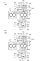
- FIG.3 (A) shows the state before starting prepressurization
- FIG.3 (B) shows the state which is performing prepressurization.
- FIG.4 (A) is the state of the discharge part in discharge operation
- FIG.4 (B) is discharge in standby operation.
- FIG. 4C shows the state of the discharge portion when the nozzle is replaced. It is a flow chart for explaining the mechanical foaming method concerning the embodiment of the present invention.
- 6 is a subroutine flowchart for explaining the control of backflow suppression (step S18) of FIG. 5.
- 6 is a flowchart of a subroutine for explaining the preliminary pressurization (step S20) of FIG.
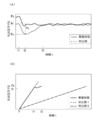
- FIG. 8 (A) is a graph showing the change over time of the discharge pressure during the discharge operation
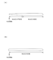
- FIG. 8 (B) is a graph showing the change over time of the discharge pressure during preliminary pressurization. It is a figure which shows the state of the foam discharged in the shape of a bead by the discharge conditions shown to FIG. 8 (A), FIG.
- FIG. 9 (A) shows the state of the foam which concerns on comparison
- FIG. 9 (B) is. 3 shows a state of the foam according to the embodiment. It is drawing which represented typically the mode of the deformation
- the curable composition for mechanical foaming according to the present invention is a curable composition for mechanical foaming having a complex viscosity ⁇ * that satisfies the following conditions (A) and (B) in the frequency dependence measurement with a rheometer.
- the cured form of the curable composition for mechanical foaming is not moisture-curable (first embodiment): Condition (A): ⁇ * at 25 ° C. and 0.1 Hz is in the range of 1000 to 50000 Pa ⁇ s, Condition (B): ⁇ * at 10.0 Hz at 25 ° C. is in the range of 100 to 1000 Pa ⁇ s.
- the foam when mechanically foaming, the foam is uniformly dispersed, and the foam can be well formed without floating on the liquid surface. ..
- condition (A) in the frequency dependence measurement by a rheometer, condition (A): ⁇ * at 25 ° C. and 0.1 Hz is in the range of 1000 to 50000 Pa ⁇ s.
- ⁇ * at 0.1 Hz at 25 ° C. is in the above range, the effect of the invention described above is effectively exhibited.
- ⁇ * at 0.1 Hz at 25 ° C. is preferably in the range of 1000 to 30000 Pa ⁇ s, more preferably 1500 to 22000 Pa ⁇ s.
- condition (B) in the frequency dependency measurement by a rheometer, the condition (B) is: condition (B): ⁇ * at 25 ° C. and 10.0 Hz is in the range of 100 to 1000 Pa ⁇ s. Is.
- ⁇ * at 25 ° C. and 10.0 Hz is in the above range, it is excellent in that the effects of the invention described above can be effectively exhibited.
- ⁇ * at 10.0 Hz at 25 ° C. is preferably in the range of 100 to 900 Pa ⁇ s, and more preferably in the range of 125 to 750 Pa ⁇ s.
- condition (C) at 25 ° C., ( ⁇ * at 0.1 Hz) / ( ⁇ * at 10.0 Hz) is in the range of 70.0 or less. Is preferred. When the conditions (A) and (B) are satisfied and ( ⁇ * at 0.1 Hz) / ( ⁇ * at 10.0 Hz) at 25 ° C. is in the range of 70.0 or less, the effects of the invention described above. Is excellent in that it can be effectively expressed. From this viewpoint, ⁇ * (0.1 Hz) / ⁇ * (10.0 Hz) under condition (C) is preferably in the range of 5.0 to 50, and more preferably in the range of 5.0 to 43. More preferable.
- ⁇ Frequency dependence measurement of a curable composition for mechanical foaming with a rheometer (complex viscosity ⁇ * measurement)>
- the ⁇ * (complex viscosity) of the curable composition for mechanical foaming (state before foaming and before curing) of the present invention is determined by measuring the frequency dependence of a rheometer.
- a rheometer HAAKE MARS III manufactured by Thermo Fisher Scientific Co., Ltd. is used as a rheometer
- P35 is used as a rotor
- the viscosity at each frequency (f (Hz)) in a 25 ° C. atmosphere is controlled by a temperature control facility. taking measurement.
- the rotor gap is 0.5 mm or 1 mm
- the measurement mode is strain control (CD control) (0. (0.5 to 0.5%) or stress control (CS control) (1 to 30 Pa) was set and measured (see Table 2 of the example), but the setting conditions are not necessarily limited to these. ..
- the rheometer is not limited to HAAKE MARS III, and other commercially available products may be used.
- the rotor is not limited to P35, and other commercially available products may be used.
- the rheometer HAAKE MARS III is equipped with a strain sensor and a stress sensor, and it is possible to optimally use strain control (CD control) and stress control (CS control) with a curable composition for mechanical foaming. If either of them is used for measurement, the same value will be output.
- CD control strain control
- CS control stress control
- the strain control since the strain per unit area is used, a numerical value obtained by multiplying the dimensionless number (angle ⁇ ° in FIG. 10) by 100 is used, and therefore the unit is represented by “%”.
- the unit is represented by "Pa" because of the shear stress per unit area.
- FIG. 10 shows the direction of the arrow in the xy coordinate diagram ((0, xy coordinate) in the xy coordinate diagram when a cross section of a cubic object (curable composition for mechanical foaming) is displayed on the xy coordinate as a length of one side.
- the state of the object before deformation (FIG. 10A) and after deformation (FIG. 10B) when a load (dynamic stress) is applied from 1) to the (1, 1) coordinate) ( 5 is a diagram schematically showing a deformation amount ⁇ 1 and a deformation angle ⁇ ).
- Optimum use of strain control (CD control) and stress control (CS control) depending on the curable composition for mechanical foaming the following is performed.
- CD control strain control
- CS control stress control
- the Lissajous figure is a figure in which the relationship between stress and strain of one cycle (reciprocating) is drawn in two-dimensional coordinates because dynamic strain occurs when dynamic stress is applied to an object. The larger the strain delay (phase difference) with respect to the stress, the closer the minor-long axis ratio of the ellipse is to 1, and the smaller the phase difference, the closer to 0.
- a commercially available curable composition as used in Examples and Comparative Examples has a retardation of around 0.5. As mentioned above, check whether the measurement can be performed optimally based on the deviation and the shape of the figure. Then, the linear region can be confirmed from the yield stress described above.
- the curable form of the curable composition for mechanical foaming of the present invention is not particularly limited as long as it is not moisture curable.
- the curable composition for mechanical foaming is cured by moisture, the appearance of the foamed state after mechanical foaming (before curing) using the curable composition for mechanical foaming as a liquid becomes poor, and after mechanical foaming. In addition, the foaming state after curing becomes poor, which is not preferable.
- a cured form of the curable composition for mechanical foaming of the present invention for example, at least one selected from the group consisting of room temperature curable, thermosetting and photocurable is preferable.
- the appearance of the foamed state after mechanical foaming (before curing) and the foamed state after mechanical foaming and after curing are excellent, there is no limit to the pot life when mechanical foaming, and it is easy to handle. More preferable.
- the viscosity increases after mixing the curable composition for mechanical foaming and the gas, so the pot life is determined, but if it is within the pot life, it can be used sufficiently. It is possible.
- compositions correspond to those in which the curable composition for mechanical foaming, which is excluded from the present invention, has a curable form of moisture curability. That is, as the composition having moisture curability, a composition containing (1) a resin (compound) having a hydrolyzable silyl group and a moisture curable catalyst (mainly tin catalyst, titanium catalyst, zirconium catalyst) (2) A composition containing a resin (compound) having an isocyanate group, a polyol, and a moisture-curable catalyst (mainly tin catalyst, titanium catalyst, zirconium catalyst) is applicable. These compositions (1) and (2) are excluded from the curable composition for mechanical foaming of the present invention, and the curable form of the curable composition for mechanical foaming is a moisture-curable one (having a moisture-curable property). Composition).
- the curable composition for mechanical foaming according to the present invention is not limited in any kind or curing type of the resin except the moisture curable resin, but it is necessary to have the above-mentioned viscosity characteristics, and the present invention described later
- the resin or the foamable material By preventing the resin or the foamable material from flowing back to the gas supply unit when switching the operating state from the standby operation to the discharge operation described in the section of the method for manufacturing a foam, the desired expansion ratio is stabilized. It is useful for use in obtainable mechanical foaming equipment.
- Such a curable composition for mechanical foaming is a one-pack type before use, exhibits a high-viscosity viscous paste state in a heated state, and has a mechanism in which the progress of curing reacts and cures. It refers to a mechanism that solidifies when cooled from a molten state to room temperature, a mechanism that crosslinks and cures by heat energy, light, radiation energy, and the like.
- thermosetting type hot melt type, sol-gel type, vulcanization curing type, light / radiation curing type, polyurethane type, silicone type, epoxy type, synthetic rubber type, polyolefin type, polyester type, acrylic resin type, polychlorinated type.
- a composition containing a vinyl-based or other thermoplastic or elastomer as a component and using a monomer, an oligomer or a polymer of a thermoplastic or thermosetting material can be mentioned.
- the curable composition for mechanical foaming is a curable composition for mechanical foaming having a complex viscosity ⁇ * satisfying the above conditions (A) and (B) in the frequency dependence measurement with a rheometer.
- the curable composition for foaming may be any one characterized in that it is not moisture-curable, and may be a one-part composition in which all the components are already mixed, or a mixture of multiple preparations before use.
- the composition can also be used.
- the composition composed of a plurality of preparations is preferably a two-pack type.
- the curing form of the one-pack type composition may be thermosetting, photo-curing, room temperature curing (anaerobic curing), etc., and the curing form of the two-pack type composition may be after mixing a plurality of preparations. Room temperature curability and the like, but the invention is not limited thereto.
- thermosetting composition a composition containing a compound having a (meth) acryloyl group and an organic peroxide, a composition containing a compound having a cyclic ether group and a curing agent and / or a curing accelerator, allyl
- a composition containing a compound having a group or a vinyl siloxane group, a cross-linking agent, and a catalyst examples thereof include a composition containing a compound having an isocyanate group and a curing agent.
- the main skeleton of each compound is polyurethane skeleton; polyether skeleton; polyester skeleton; polycarbonate skeleton; polyurethane modified skeleton; polyepoxy modified skeleton; polyurea skeleton; polyorganosiloxane skeleton; polybutadiene skeleton, polyisoprene skeleton, polyisobutylene skeleton, etc.
- Various skeletons such as, but not limited to, the polyolefin skeletons; poly (meth) acrylate skeletons and their hydrogenated skeletons can be used.
- the one-pack type photocurable composition a composition containing a compound having a (meth) acryloyl group and a photoinitiator, a composition having a cyclic ether group (including a cyclic thioether group) and a photoacid generator And so on.
- the main skeleton of each compound is polyurethane skeleton; polyether skeleton; polyester skeleton; polycarbonate skeleton; polyurethane modified skeleton; polyepoxy modified skeleton; polyurea skeleton; polyorganosiloxane skeleton; polybutadiene skeleton, polyisoprene skeleton, polyisobutylene skeleton, etc.
- Various skeletons such as, but not limited to, the polyolefin skeletons; poly (meth) acrylate skeletons and their hydrogenated skeletons can be used.
- the one-pack type anaerobic curable composition includes a composition containing a compound having a (meth) acryloyl group, an organic peroxide and an anaerobic catalyst.
- the main skeleton of each compound is polyurethane skeleton; polyether skeleton; polyester skeleton; polycarbonate skeleton; polyurethane modified skeleton; polyepoxy modified skeleton; polyurea skeleton; polyorganosiloxane skeleton; polybutadiene skeleton, polyisoprene skeleton, polyisobutylene skeleton, etc.
- Various skeletons such as, but not limited to, the polyolefin skeletons; poly (meth) acrylate skeletons and their hydrogenated skeletons can be used.
- a compound having a (meth) acryloyl group, an organic peroxide, and a metal catalyst are divided into a plurality of preparations, a compound having a cyclic ether group, a curing agent, and / or a curing accelerator.
- examples thereof include a composition in which the agent is divided into a plurality of preparations, a composition in which a compound having an allyl group or a vinyl siloxane group, a crosslinking agent, and a catalyst are divided into a plurality of preparations.
- the main skeleton of each compound is polyurethane skeleton; polyether skeleton; polyester skeleton; polycarbonate skeleton; polyurethane modified skeleton; polyepoxy modified skeleton; polyurea skeleton; polyorganosiloxane skeleton; polybutadiene skeleton, polyisoprene skeleton, polyisobutylene skeleton, etc.
- Various skeletons such as, but not limited to, the polyolefin skeletons; poly (meth) acrylate skeletons and their hydrogenated skeletons can be used. Further, it is possible to impart curability such as photocurability and anaerobic curability to the two-part curable composition, and it is also possible to heat the composition after leaving it at room temperature for gelation.
- a filler such as an inorganic filler or an organic filler can be appropriately added to the curable composition for mechanical foaming in order to adjust the viscosity and thixotropy.
- the filler may be added in an amount of 0.001 to 1000 parts by mass with respect to 100 parts by mass of the resin component.
- the average particle size of the filler is 0., from the viewpoint of easy dispersion and the complex viscosity ⁇ * satisfying the above conditions (A) and (B) of the curable composition for mechanical foaming can be easily adjusted.
- the thickness is preferably 001 to 100 ⁇ m, more preferably 0.01 to 50 ⁇ m, and particularly preferably 0.1 to 20 ⁇ m.
- the method for measuring the average particle size includes, but is not limited to, the laser diffraction method and the SEM (scanning electron microscope) method.
- the curable composition for mechanical foaming of the present invention is a group consisting of room temperature curability such as two-component curable type excluding moisture curability, anaerobic curability, thermosetting and photocurability, which are the best curing forms. At least one selected from the group consisting of a vinyl group (for example, (meth) acryl group, allyl group, vinylsiloxane group, vinyl ether group, etc.) and a cyclic group which are useful and versatile and whose curing form can be freely changed.
- a vinyl group for example, (meth) acryl group, allyl group, vinylsiloxane group, vinyl ether group, etc.
- a cyclic group which are useful and versatile and whose curing form can be freely changed.
- a resin having at least one reactive functional group selected from the group consisting of an ether group (for example, an epoxy group, a glycidyl group, an oxetanyl group, an oxetane group, etc.).
- an ether group for example, an epoxy group, a glycidyl group, an oxetanyl group, an oxetane group, etc.
- the resin (compound) having a vinyl group that can be used in the present invention includes a (meth) acryloyl group (hereinafter, the acryloyl group and the methacryloyl group are collectively referred to as a (meth) acryloyl group, and a (meth) acryloyl group is also included.
- a resin (compound) having a (meth) acrylamide group hereinafter, a combination of an acrylamide group and a methacrylamide group is also referred to as a (meth) acrylamide group). , But not limited to these.
- the (meth) acrylate oligomer examples include a (meth) acrylate oligomer having an ester bond in the molecule, a (meth) acrylate oligomer having an ether bond, a (meth) acrylate oligomer having a urethane bond, and an epoxy-modified (meth) acrylate.
- examples thereof include oligomers (acryl-modified compounds having terminal epoxy groups), and the main skeletons thereof include, but are not limited to, bisphenol A, novolac phenol, polybutadiene, polyester, and polyether.
- a urethane-modified (meth) acrylate oligomer is particularly preferable from the viewpoint of improving the adhesive strength.
- the oligomer is, for example, a polyol compound having two or more hydroxyl groups in the molecule, a compound having two or more isocyanate groups in the molecule, and (meth) acrylate containing at least one hydroxyl group in the molecule. It is synthesized from the reaction products of and.
- the compound having two or more isocyanate groups in the molecule include aromatic polyisocyanate, alicyclic polyisocyanate, aliphatic polyisocyanate, and the like, and among them, a cured product having flexibility is obtained.
- Aliphatic polyisocyanates and alicyclic polyisocyanates are preferred. These may be used alone or in combination of two or more.
- polyol compound having two or more hydroxyl groups in the molecule used for oligomer synthesis examples include polyether polyol, polyester polyol, caprolactone diol, bisphenol polyol, polyisoprene polyol, hydrogenated polyisoprene polyol, polybutadiene polyol, hydrogenated polybutadiene.
- examples include polyols, castor oil polyols, polycarbonate diols, and polysilanols.
- polycarbonate diols polybutadiene polyols, and hydrogenated polybutadiene polyols are preferable because of their excellent transparency and durability, and particularly preferable are polycarbonate diols from the viewpoint that the cured product does not become cloudy in a high temperature and high humidity atmosphere. Be done. These may be used alone or in combination of two or more.
- Aromatic polyisocyanates and aliphatic polyisocyanates are compounds that have two or more isocyanate groups in the molecule for oligomer synthesis.
- Aromatic polyisocyanates include 2,4-tolylene diisocyanate, 2,6-tolylene diisocyanate, 1,3-xylylene diisocyanate, 1,4-xylylene diisocyanate, tetramethylxylylene diisocyanate, diphenylmethane diisocyanate, naphthalene- 1,5-disocyanate, triphenylmethane triisocyanate and the like can be mentioned.
- Examples of the alicyclic polyisocyanate include isophorone diisocyanate, bis (4-isocyanatocyclohexyl) methane, 1,3-bis (isocyanatomethyl) cyclohexane, 1,4-bis (isocyanatomethyl) cyclohexane, norbornane diisocyanate, bicycloheptane. Examples thereof include triisocyanate. Examples of the aliphatic polyisocyanate include hexamethylene diisocyanate, 1,3,6-hexamethylene triisocyanate and 1,6,11-undecatriisocyanate. Of these, diisocyanates such as isophorone diisocyanate and hexamethylene diisocyanate are preferable.
- Examples of the (meth) acrylate containing at least one hydroxyl group in the molecule used for oligomer synthesis include, for example, ethylene glycol, propylene glycol, 1,3-propanediol, 1,3-butanediol, 1,4 -Mono (meth) acrylates of dihydric alcohols such as butanediol and polyethylene glycol, mono (meth) acrylates or di (meth) acrylates of trihydric alcohols such as trimethylolethane, trimethylolpropane and glycerin. ..
- mono (meth) acrylates of dihydric alcohols are preferable, and mono (meth) acrylates of ethylene glycol are more preferable, from the viewpoint of obtaining a cured product having excellent flexibility.
- mono (meth) acrylates of dihydric alcohols are preferable, and mono (meth) acrylates of ethylene glycol are more preferable, from the viewpoint of obtaining a cured product having excellent flexibility.
- These may be used alone or in combination of two or more.
- the method for synthesizing the urethane-modified (meth) acrylate oligomer is not particularly limited, and a known method can be used.
- a polyol compound having two or more hydroxyl groups in the molecule and an isocyanate compound having two or more isocyanate groups in the molecule are preferably used in a molar ratio (polyol compound: isocyanate compound) of 3: 1 to 1: 1. 3, more preferably in a ratio of 2: 1 to 1: 2 in a diluent (eg, methyl ethyl ketone, methoxyphenol, etc.) to obtain a urethane prepolymer.
- a molar ratio polyol compound: isocyanate compound
- the isocyanate group remaining in the obtained urethane prepolymer is further reacted with a (meth) acrylate having at least one hydroxyl group in the molecule in an amount sufficient to react with the isocyanate group,
- a method for synthesizing a urethane (meth) acrylate oligomer may be mentioned.
- Examples of the catalyst used in the synthesis include lead oleate, tetrabutyltin, antimony trichloride, triphenylaluminum, trioctylaluminum, dibutyltin dilaurate, copper naphthenate, zinc naphthenate, zinc octylate, zinc octenoate, Examples include zirconium naphthenate, cobalt naphthenate, tetra-n-butyl-1,3-diacetyloxydistannoxane, triethylamine, 1,4-diaza [2,2,2] bicyclooctane and N-ethylmorpholine. it can.
- dibutyltin dilaurate, zinc naphthenate, zinc octylate, and zinc octenoate are preferably used because a cured product having high activity and excellent transparency can be obtained. It is preferable to use 0.0001 to 10 parts by mass of these catalysts based on 100 parts by mass of the total amount of the reactants.
- the reaction temperature is usually 10 to 100 ° C., preferably 30 to 90 ° C.
- the urethane-modified (meth) acrylate oligomer may be diluted with a solvent or the following monomer at the stage of raw material.
- a compound whose main skeleton is a polymer of a (meth) acrylic monomer and has at least two (meth) acryloyl groups in the molecule can also be used as an oligomer.
- a reactive (meth) acryloyl group remains in the oligomer and may be present in either side chain and / or terminal of the molecule, but from the viewpoint of rubber elasticity and flexibility, It is preferably present at both ends of the chain.
- the (meth) acrylic monomer is not particularly limited, and various kinds can be used.
- the (meth) acrylic monomer is a general term for monomers having an acryloyl group or a methacryloyl group.
- (meth) acrylic acid methyl (meth) acrylate, ethyl (meth) acrylate, (meth) acrylic acid ester, (n) -propyl (meth) acrylate, isopropyl (meth) acrylate, ( (Meth) acrylic acid-n-butyl, (meth) acrylic acid isobutyl, (meth) acrylic acid-t-butyl, (meth) acrylic acid-n-pentyl, (meth) acrylic acid-n-hexyl, (meth) acrylic Acid cyclohexyl, (meth) acrylic acid-n-heptyl, (meth) acrylic acid-n-octyl, (meth) acrylic acid-2-ethylhexyl, non
- the lower limit of the number average molecular weight (Mn) of the compound whose main skeleton is composed of a polymer of a (meth) acrylic monomer and has at least two (meth) acryloyl groups in the molecule is 500, preferably 3000.
- the upper limit is 100,000, preferably 50,000.
- the molecular weight (number average molecular weight, weight average molecular weight, etc.) can be measured by gel permeation chromatography (GPC) using polystyrene as a standard substance.
- the compound having a main skeleton made of a polymer of a (meth) acrylic monomer and having at least two (meth) acryloyl groups in the molecule can be obtained by various polymerization methods, and the method is not particularly limited.
- the radical polymerization method is preferred from the viewpoints of versatility of the monomer and ease of reaction control.
- the controlled radical polymerization is preferable, the living radical polymerization is more preferable, and the atom transfer radical polymerization is particularly preferable.
- a method of introducing a (meth) acryloyl group into a polymer of a (meth) acrylic monomer, which is a main chain includes (1) a vinyl polymer having a hydroxyl group at the terminal and chlorine, bromine, or a hydroxyl group-containing ( (2) a method of reacting a vinyl polymer having a halogen group at the terminal with an alkali metal ion- or quaternary ammonium ion-containing (meth) acrylate compound; Examples thereof include a method obtained by reacting a vinyl polymer having a hydroxyl group with a diisocyanate compound and reacting a residual isocyanate group with a hydroxyl group-containing (meth) acrylate.
- a monomer in the curable composition for mechanical foaming of the present invention, can be used together with an oligomer including the above urethane-modified oligomer, and monofunctional, difunctional, trifunctional, tetrafunctional or higher polyfunctional monomers can be mentioned. Be done.
- a (meth) acrylate monomer is preferable, and a bifunctional (meth) acrylate monomer is particularly preferable.
- the monomer preferably has a molecular weight of 10,000 or less, more preferably 5000 or less, and most preferably 1000 or less.
- Examples of the monofunctional monomer include lauryl (meth) acrylate, stearyl (meth) acrylate, tetrahydrofurfuryl (meth) acrylate, caprolactone-modified tetrahydrofurfuryl (meth) acrylate, cyclohexyl (meth) acrylate, dicyclopentanyl (meth).
- bifunctional monomer examples include neopentyl glycol di (meth) acrylate, bisphenol A di (meth) acrylate, epichlorohydrin-modified bisphenol A di (meth) acrylate, stearic acid-modified pentaerythritol di (meth) acrylate, and difunctional monomer.
- trifunctional monomer examples include trimethylolpropane tri (meth) acrylate, pentaerythritol tri (meth) acrylate, epichlorohydrin-modified trimethylolpropane tri (meth) acrylate, epichlorohydrin-modified glycerol tri (meth) acrylate. , Tris (acryloyloxyethyl) isocyanurate and the like.
- polyfunctional monomer examples include ditrimethylolpropane tetra (meth) acrylate, pentaerythritol tetra (meth) acrylate, dipentaerythritol monohydroxypenta (meth) acrylate, alkyl-modified dipentaerythritol pentaacrylate, and dipentaerythritol hexa (meta).
- examples include acrylate. These polymerizable monomers may be used alone or in combination of two or more.
- Examples of the (meth) acrylamide monomer include, but are not limited to, dimethylacrylamide, acryloylmorpholine, and diethylacrylamide. Considering price and availability, diethyl acrylamide or dimethyl acrylamide is preferable. Specific examples include DMAA (registered trademark), ACMO (registered trademark), and DEAA (registered trademark) manufactured by KJ Chemicals Co., Ltd., but are not limited thereto.
- a photoinitiator can be added to the (meth) acryloyl group to impart photocurability.
- examples include acetophenone photoinitiators, benzoin photoinitiators, benzophenone photoinitiators, thioxanthone photoinitiators, and acylphosphine oxide photoinitiators. These may be used alone or in combination of two or more.
- an acylphosphine oxide photoinitiator that is easily cured by energy rays in the visible light region is added to a curable composition for mechanical foaming, the curable composition for mechanical foaming itself tends to be yellow, but the photocurability is improved.
- an acylphosphine oxide photoinitiator is preferred.
- acetophenone-based photoinitiator examples include diethoxyacetophenone, 2-hydroxy-2-methyl-1-phenylpropan-1-one, benzyldimethylketal, 4- (2-hydroxyethoxy) phenyl- (2-hydroxy- 2-propyl) ketone, 1-hydroxycyclohexyl phenyl ketone, 2-methyl-2-morpholino (4-thiomethylphenyl) propan-1-one, 2-benzyl-2-dimethylamino-1- (4-morpholinophenyl) Examples thereof include butanone, 2-hydroxy-2-methyl-1- [4- (1-methylvinyl) phenyl] propanone oligomer, but not limited thereto.
- benzoin-based photoinitiator examples include, but are not limited to, benzoin, benzoin methyl ether, benzoin ethyl ether, benzoin isopropyl ether, and benzoin isobutyl ether.
- benzophenone photoinitiator examples include benzophenone, methyl o-benzoylbenzoate, 4-phenylbenzophenone, 4-benzoyl-4′-methyl-diphenyl sulfide, 3,3 ′, 4,4′-tetra (t- (Butylperoxycarbonyl) benzophenone, 2,4,6-trimethylbenzophenone, 4-benzoyl-N, N-dimethyl-N- [2- (1-oxo-2-propenyloxy) ethyl] benzenemethanaminium bromide, ( 4-benzoylbenzyl) trimethylammonium chloride can be mentioned, but not limited thereto.
- Examples of the thioxanthone photoinitiator include 2-isopropylthioxanthone, 4-isopropylthioxanthone, 2,4-diethylthioxanthone, 2,4-dichlorothioxanthone, 1-chloro-4-propoxythioxanthone, and 2- (3-dimethylamino). Examples thereof include, but are not limited to, -2-hydroxy) -3,4-dimethyl-9H-thioxanthone-9-one mesochloride.
- acylphosphine oxide photoinitiator examples include bis (2,4,6-trimethylbenzoyl) -phenylphosphine oxide, 2,4,6-trimethylbenzoyl-diphenylphosphine oxide and 2,4,6-trimethyl. Examples thereof include, but are not limited to, benzoylphenylethoxyphosphine oxide.
- Thermosetting can also be imparted by adding an organic peroxide to the (meth) acryloyl group.
- organic peroxides include ketone peroxides such as methyl ethyl ketone peroxide, cyclohexanone peroxide, 3,3,5-trimethylcyclohexanone peroxide, methyl cyclohexanone peroxide, methyl acetoacetate peroxide, and acetylacetone peroxide.
- Anaerobic curability can be imparted by adding an anaerobic curable catalyst such as saccharin represented by the following formula 1 to the (meth) acryloyl group.
- an anaerobic curable catalyst such as saccharin represented by the following formula 1
- the metal ions of the adherend react with the saccharin to decompose the organic peroxide and generate free radicals.
- the metal catalyst include a copper compound and / or a vanadium compound. Copper compounds and / or vanadium compounds are optimal because other metals do not provide sufficient reactivity. Specific examples of copper compounds include, but are not limited to, copper chloride, copper acetate, copper naphthenate, copper acetylacetonate, and the like. Specific examples of the vanadium compound include, but are not limited to, vanadyl acetylacetonate, vanadium stearate, vanadium naphthate, and vanadium pentoxide.
- Examples of compounds that promote room-temperature curability when the organic peroxide and the metal catalyst are used together in the (meth) acryloyl group include N, N-dimethylaniline, N, N-dimethyl-P-toluidine, and diisopropanol-
- Examples of tertiary amines such as P-toluidine and triethylamine include polyamines such as diethylenetriamine, triethylenetetramine and pentaethylenehexamine, and thioureas such as thiourea, ethylenethiourea, benzoylthiourea, acetylthiourea and tetramethylthiourea.
- the present invention is not limited to these.
- a compound containing an allyl group or vinyl siloxane group is included as a main agent, a cross-linking agent having a hydrogen siloxane group, a catalyst, and an inhibitor, and the main agent and the cross-linking agent are polymerized by an addition reaction (hydrosilation or hydrosilylation) due to heat. Can be cured.
- the one-pack type containing all the components can be imparted with thermosetting property, and the two-component type in which these components are divided into two can also be imparted with the room temperature curing property.
- the inhibitor is a compound that suppresses the activity of the catalyst.
- the curing temperature is preferably 80 to 160 ° C., preferably 100 to 150 ° C., and the curing time is preferably 3 to 90 minutes.
- a compound having an allyl group or vinyl siloxane group is an oligomer having one or more functional groups in one molecule.
- the skeleton of the main agent include a dimethylsiloxane skeleton, a polyisobutylene skeleton, a polyisoprene skeleton, a polybutadiene skeleton, and a hydrogenated type of those having a carbon-carbon double bond.
- Hydrogenation which is also called hydrogenation, is a reduction reaction in which a hydrogen atom is added to a compound using hydrogen gas as a reducing agent, and an unsaturated bond existing in a molecule is converted to a saturated bond.
- the main skeleton containing no polydimethylsiloxane is a polymer of a (meth) acryl monomer and has at least two (meth) acryloyl groups in the molecule.
- a polybutadiene skeleton or a hydrogenated polybutadiene skeleton having a good As a specific example of the main agent contained in the compound having a main skeleton made of a polymer of a (meth) acryl monomer and having at least two (meth) acryloyl groups in the molecule, Epion (registered trademark) series manufactured by Kaneka Corporation. (A type) and the like, but the invention is not limited thereto.
- the cross-linking agent is a compound having one or more hydrogen siloxane groups in one molecule, and may be a compound having a hydrogen siloxane group, or may be a modified compound. Those having compatibility with the main agent are particularly preferable.
- Specific examples of the cross-linking agent whose main skeleton is a polymer of a (meth) acrylic monomer and which is contained in a compound having at least two (meth) acryloyl groups in the molecule include Kaneka Epion (registered trademark) manufactured by Kaneka Corporation.
- CR series such as CR-300 and CR-500
- hydrosiloxanes such as HMS-013, HMS-151 and HMS-301 manufactured by Asmax Co., Ltd.
- HMS-013, HMS-151 and HMS-301 manufactured by Asmax Co., Ltd. hydrosiloxanes
- SH1107 fluid manufactured by Toray Dow Corning Co., Ltd. it is not limited to these.
- the specific example of the addition reaction catalyst is not limited as long as it is a metal catalyst used for addition reaction of a compound having an allyl group or a vinyl siloxane group and a compound having hydrogen added to silicon.
- Particularly preferable catalysts are platinum-based and / or rhodium-based catalysts because of their price and variety.
- a divalent tetramethyldisiloxane platinum complex for a 0-valent platinum complex a tetravinyltetramethyltetracyclosiloxane platinum complex for a divalent platinum complex, a dichlorobistriphenylphosphine palladium complex for a divalent platinum complex, and a chloride for a tetravalent platinum complex.
- Examples include, but are not limited to, platinic acid.
- Specific examples of the rhodium-based catalyst include a chlorotristriphenylphosphite rhodium complex for a monovalent rhodium complex, a tetrakisacetate dirhodium complex for a divalent rhodium complex, and a trisacetylacetonatotrodium complex for a trivalent rhodium complex.
- the present invention is not limited to this. Further, two or more kinds of catalysts may be mixed and used.
- the inhibitor examples include 1-ethynyl-1-cyclohexanol, 2-methyl-3-butyn-2-ol, 3,5-dimethyl-1-hexyne-3-ol and 3-methyl as acetylenic alcohols. -1-dodecin-3-ol and the like can be mentioned.
- polymethylvinylcyclosiloxane examples include 1,3,5,7-tetravinyltetramethyltetracyclosiloxane, divinyltetramethyldisiloxane, tetravinyldimethyldisiloxane, and trialkylcyanurate.
- Other examples include, but are not limited to, diallyl maleate, dimethyl maleate, diethyl maleate, diallyl fumarate, diethyl fumarate and the like.
- a vinyl ether compound may be used together with a compound having an allyl group or a vinyl siloxane group, for example, ethylene glycol divinyl ether, 1,3-propanediol divinyl ether, propylene glycol divinyl ether, 1,4-butanediol divinyl ether, 1 , 3-butanediol divinyl ether, 1,2-butanediol divinyl ether, 2,3-butanediol divinyl ether, 1-methyl-1,3-propanediol divinyl ether, 2-methyl-1,3-propanediol di Vinyl ether, 2-methyl-1,2-propanediol divinyl ether, 1,5-pentanediol divinyl ether, 1,6-hexanediol divinyl ether, cyclohexane-1,4-diol divinyl ether, cyclohexane-1,4-d
- the cyclic ether group contained in the resin (compound) having a cyclic ether group is preferably a 3-membered ring or a 4-membered ring, and as the 3-membered ring, an epoxy group (glycidyl group), an alicyclic epoxy group (cycloalkene oxide), etc.
- examples of the 4-membered ring include an oxetane group, but are not limited thereto.
- Specific examples of the resin (compound) having a cyclic ether group include an epoxy resin, an alicyclic epoxy resin, an oxetane resin, and the like. However, the resin (compound) is not limited to these, and two or more kinds of them may be combined. Good. Further, a cyclic thioether group (thiirane group) can also be used.
- the epoxy resin preferably contains a compound having two or more epoxy groups in one molecule. You may use only 1 type and may mix and use 2 or more types. Specific examples of the epoxy resin include those obtained by condensation of epichlorohydrin with polyhydric phenols such as bisphenols and polyhydric alcohols, and include, for example, bisphenol A type, brominated bisphenol A type, hydrogenated bisphenol A type, and bisphenol.
- Glycidyl ether type such as F type, bisphenol S type, bisphenol AF type, biphenyl type, naphthalene type, fluorene type, novolac type, phenol novolac type, orthocresol novolac type, tris (hydroxyphenyl) methane type, tetraphenylolethane type
- An epoxy resin can be exemplified.
- Glycidyl ester type epoxy resin obtained by condensation of epichlorohydrin with carboxylic acid such as phthalic acid derivative and fatty acid glycidyl amine type epoxy resin obtained by reaction of epichlorohydrin with amines, cyanuric acids, hydantoins, and various other Examples thereof include epoxy resins modified by the method, but are not limited thereto.
- Examples of commercially available bisphenol type epoxy resins include jER (registered trademark) series manufactured by Mitsubishi Chemical Corporation, 827, 828EL, YL983U, and EPICLON (registered trademark) series manufactured by DIC Corporation, 830, EXA-835LV. Etc.
- Other Epotote series manufactured by Nippon Steel & Sumikin Co., Ltd. include YD-128 and YDF-170, but are not limited to these.
- the epoxy resin preferably contains a compound having three or more epoxy groups and an aromatic ring in one molecule.
- the aromatic ring include a benzene ring, a naphthalene ring and an aniline ring.
- Specific examples of the trifunctional compound include N, N-bis (2,3-epoxypropyl) -4- (2,3-epoxypropoxy) aniline and N, N-bis (2,3-epoxypropyl). -4- (2,3-epoxypropoxy) -2-methylaniline and the like can be mentioned.
- specific examples of the tetrafunctional compound include diaminodiphenylmethane tetraglycidyl ether.
- Tg can be increased by adding a compound having three or more epoxy groups and an aromatic ring in one molecule.
- the curable composition for mechanical foaming of the present invention may contain a compound having one epoxy group in one molecule and is generally called a reactive diluent.
- a reactive diluent Specifically, phenylglycidyl ether, Cresyl glycidyl ether, pt-butylphenyl glycidyl ether, 2-ethylhexyl glycidyl ether, butyl glycidyl ether, C12-14 (C12-C14) alcohol glycidyl ether, butane diglycidyl ether, hexane diglycidyl ether, cyclohexane dimethyl Examples include, but are not limited to, diglycidyl ether, or glycidyl ether based on polyethylene glycol or polypropylene glycol.
- the reactive diluent is preferable from the viewpoint of lowering the viscosity and appearance.
- a compound having an alicyclic epoxy group is an epoxy compound mainly having an epoxycyclohexyl group.
- Specific examples thereof include 3,4-epoxycyclohexylmethyl-3,4-epoxycyclohexanecarboxylate, bis (3,4-epoxycyclohexylmethyl) adipate, 2- (3,4-epoxycyclohexyl-5,5-spiro).
- -3,4-epoxy) cyclohexanone-m-dioxane, bis (2,3-epoxycyclopentyl) ether and the like can be mentioned, but the invention is not limited thereto.
- the compound having an oxetane group include 3- (meth) allyloxymethyl-3-ethyloxetane, isobornyloxyethyl (3-ethyl-3-oxetanylmethyl) ether, isobornyl (3-ethyl-3-) Monofunctional oxetane compounds such as oxetanylmethyl) ether, 2-ethylhexyl (3-ethyl-3-oxetanylmethyl) ether, dicyclopentadiene (3-ethyl-3-oxetanylmethyl) ether, 3,7-bis (3-oxetanyl) ) -5-Oxa-nonane, 1,2-bis [(3-ethyl-3-oxetanylmethoxy) methyl] ethane, 1,2-bis [(3-ethyl-3-oxetanylmethoxy) methyl] propane, dicyclo Pentenyl bis (3-e)
- the compound having a thiirane group examples include 2,2-bis (4- (2,3-epithiopropoxy) phenyl) propane, bis (4- (2,3-epithiopropoxy) phenyl) methane, 1 , 6-di (2,3-epithiopropoxy) naphthalene, 1,1,1-tris- (4- (2,3-epithiopropoxy) phenyl) ethane, 2,2-bis (4- (2,2 3-epithiopropoxy) cyclohexyl) propane, bis (4- (2,3-epithiopropoxy) cyclohexyl) methane, 1,1,1-tris- (4- (2,3-epithiopropoxy) cyclohexyl) ethane , 1,5-pentanediol 2,3-epithiocyclohexyl) ether, 1,6-hexanediol di (3,4-epith
- a curing agent and / or a curing accelerator can be added to impart a thermosetting property or a room temperature curing property to a resin (compound) having a cyclic ether group.
- the curing agent include polyamine compounds, polyphenol compounds, polythiol compounds and acid anhydrides, and examples of the curing accelerator include tertiary amine compounds.
- polyamine compound examples include dicyandiamide, dihydrazine, diethylenetriamine, triethylenetetramine, metaxylylenediamine, isophoronediamine, 1,3-bisaminomethylcyclohexane, diaminodiphenylmethane, metaphenylenediamine, diaminodiphenylsulfone, dicyandiamide, Examples thereof include organic acid dihydrazide and piperidine, but are not limited thereto.
- polyphenol compounds include novolak type phenol resins obtained by reacting phenols such as phenol and alkylphenols with aldehydes such as formaldehyde and paraformaldehyde, and zylog type phenol resins which are modified phenol novolac resins.
- examples thereof include, but are not limited to, polyhydric phenol resins such as dicyclopentadiene type phenol resin and polyfunctional type phenol resin.
- a polyphenol compound which is liquid at room temperature is particularly preferable.
- polythiol compound examples include 3-methoxybutyl 3-mercaptopropionate, 2-ethylhexyl 3-mercaptopropionate, tridecyl 3-mercaptopropionate, trimethylolpropane tristhiopropionate, pentaerythritol.
- Tetrakisthiopropionate methylthioglycolate, 2-ethylhexylthioglycolate, ethylene glycol bisthioglycolate, 1,4-butanediol bisthioglycolate, trimethylolpropane tristhioglycolate, pentaerythritol tetrakisthioglycolate , Di (2-mercaptoethyl) ether, 1-butanethiol, 1-hexanethiol, cyclohexylmercaptan, 1,4-butanedithiol, 3-mercapto-2-butanol, ⁇ -mercaptopropyltrimethoxysilane, benzenethiol, benzylmercaptan 1,3,5-trimercaptomethylbenzene, 1,3,5-trimercaptomethyl-2,4,6-trimethylbenzene, terminal thiol group-containing polyether, terminal thiol group-containing poly
- the acid anhydride examples include dodecenyl succinic anhydride, polyazelaic anhydride, hexahydrophthalic anhydride, tetrahydrophthalic anhydride, methyltetrahydrophthalic anhydride, methylnadamic anhydride, trimellitic anhydride and pyromellitic anhydride.
- Cyclic acid anhydrides such as benzophenone tetracarboxylic acid anhydride, tetrabromophthalic anhydride, and head acid anhydride are preferable, but not limited thereto.
- a tertiary amine compound etc. may be used as a curing accelerator (latent curing agent).
- the curing accelerator is generally a solid at room temperature, and a compound having a solid imidazole skeleton or a fine powder obtained by pulverizing an epoxy adduct compound that stops the reaction midway by adding a tertiary amine to an epoxy resin, etc. Is used.
- epoxy adduct compounds include the Amicure (registered trademark) series manufactured by Ajinomoto Fine-Techno Co., Inc., the Fujicure (registered trademark) series manufactured by T & K TOKA Co., Ltd., and the Novacure (registered trademark) manufactured by Asahi Kasei Chemicals Corporation. Examples include series.
- organic phosphorus compounds, organic amine compounds, imidazole derivative compounds and the like are known as curing accelerators that are liquid at room temperature.
- a curing accelerator can also be used as a curing agent depending on the case.
- a photoacid generator can be used to impart photocurability to a resin (compound) having a cyclic ether group. Any compound can be used as long as it can generate an acid by irradiation with energy rays.
- Specific examples of the photoacid generator include salts in which the cation species are iodonium cation species and sulfonium cation species, and the anion species are phosphorus anion species and boron anion species. The above can be used in combination. Further, a nonionic photo-acid initiator can also be used.
- the photoacid generator other than salts include, but are not limited to, diazomethane derivatives, triazine derivatives and imidyl sulfonate derivatives.
- haloalkyltriazinyl such as 1-methoxy-4- (3,5-di (trichloromethyl) triazinyl) benzene and 1-methoxy-4- (3,5-di (trichloromethyl) triazinyl) naphthalene
- Resin having isocyanate group (including oligomer and the like, also referred to as compound having isocyanate group)
- compound having isocyanate group In addition to the compound having a vinyl group and the compound having a cyclic ether group, a compound having an isocyanate group can be used, and it is preferable to add an amine compound in order to impart thermosetting property to the compound having an isocyanate group.
- a one-pack type polyurethane-based curable composition for mechanical foaming comprises a urethane prepolymer having a terminal active isocyanate group (NCO group) as a component, and an active isocyanate group of the urethane prepolymer and / or polyisocyanate compound.
- NCO group terminal active isocyanate group
- a blocked urethane prepolymer and / or a blocked polyisocyanate compound which is provisionally blocked to deactivate, is used as a component.
- thermosetting type is used in combination with a latent curing agent that is activated by heating; and an ordinary curing agent and / or a heat activated latent curing agent is used as a blocked polyisocyanate compound.
- a combination of thermosetting types can also be used.
- the urethane prepolymer containing an active isocyanate group used in the one-component polyurethane-based curable composition for mechanical foaming having the above-mentioned constitution is obtained by reacting an excessive amount of a polyisocyanate compound with a polyol.
- the above polyisocyanate compound belongs to aromatic, aliphatic or alicyclic group, for example, tolylene diisocyanate (TDI), diphenylmethane diisocyanate, 3,3′-dimethyl-4,4′-biphenylene diisocyanate, 1,4 -Phenylene diisocyanate, xylylene diisocyanate, tetramethyl xylylene diisocyanate, naphthylene diisocyanate, dicyclohexylmethane-4,4'-diisocyanate, crude TDI, polymethylene polyphenyl isocyanate, isophorone diisocyanate, hexamethylene diisocyanate, hydrogenated xylylene diisocyanate Isocyanates, their isocyanurates, carbodiimides, burettes and the like can be mentioned, and one kind or a mixture of two or more kinds thereof can be used.
- TDI tolylene diiso
- polyol component ethylene glycol, propylene glycol, glycerin, trimethylolpropane, pentaerythritol, sorbitol, alkylene oxide such as ethylene oxide and propylene oxide, or alkylene oxide such as ethylene oxide and propylene oxide is added to polyhydric alcohol such as sucrose.
- Polyether polyols ethylene glycol, propylene glycol and their oligoglycols, butylene glycol, hexylene glycol, polyols of polytetramethylene ether glycols, polyester polyols such as polycaprolactone polyol and polyethylene adipate, polybutadiene Polyvinyl polyols such as polyols and polyisoprene polyols, higher fatty acid esters having hydroxyl groups such as castor oil, acrylic polyols, polysiloxane polyols having hydroxyl groups, polyether polyols or polyesters are graft-reacted with vinyl monomers. Other examples include polymer polyols.
- the urethane prepolymer containing an end-active isocyanate group is obtained by reacting the OH groups of the polyol component such that the NCO groups of the polyisocyanate compound have an equivalent ratio of 1.1 to 3.5 times. ..
- the reaction is carried out in the presence of a catalyst (specifically, an organotin catalyst such as dibutyltin dilaurate, a bismuth catalyst such as bismuth octylate, a tertiary amine catalyst, etc.) at room temperature to 60 to 100 ° C. Perform for 1 to 24 hours.
- a urethane prepolymer having a terminal active isocyanate group content of 0.5 to 10% by mass and a viscosity of 3 to 50 Pa ⁇ s / 20 ° C. is obtained.
- the one-pack type polyurethane-based curable composition for mechanical foaming is a urethane polymer containing a terminal active isocyanate group obtained by reacting a polyisocyanate compound and a polyol component with an excess amount of the polyisocyanate compound, respectively, or It is a mixture of deactivated solid polyamine-based latent curing agent added to the mixture.
- a fine powder having a central particle diameter of 2 ⁇ m is fixed on the surface of particles of a solid polyamine having a melting point of 50 ° C. or more and a central particle diameter of about 20 ⁇ m to inactivate by coating active amino groups.
- a fine powder coating amine is exemplified. The solid polyamine and the fine powder are fixed so that the mass ratio is 1 / 0.001 to 0.5, and the active amino groups on the surface are coated and inactivated.
- a latent curing agent that is activated by heating is used to impart thermosetting properties to the urethane prepolymer.
- inactivated solid polyamine is preferable.
- the solid polyamine for example, 76.9 parts by mass of 1,12-dodecanediamine (melting point: 71 ° C.) having a central particle size of about 8 ⁇ m and 23.1 parts by mass of fine particles of titanium oxide having a central particle size of 0.02 ⁇ m.
- the above-mentioned solid polyamine is an aromatic or aliphatic polyamine which has a melting point of 50 ° C. or higher and is solid at room temperature, specifically, 4,4′-diaminodiphenylmethane, 2,4′-diaminodiphenylmethane, 3,3 ′.
- aromatic solid polyamines such as 1,12-dodecanediamine, 2,10-decanediamine, 1,8-octanediamine, 1,14-tetradecanediamine and 1,16-hexadecanediamine. One or a mixture of two or more of these is used.
- the solid polyamine is usually ground and adjusted to have a central particle size of 20 ⁇ m or less, preferably 3 to 15 ⁇ m.
- an amino group on the particle surface of the solid polyamine is coated with an inactivating agent to inactivate it.
- an organic or inorganic fine powder is used and is fixed on the surface of the solid polyamine particles.
- the fine powder includes inorganic titanium oxide, calcium carbonate, clay, silica, zirconia, carbon, alumina, talc, etc., and fine particles of organic polyvinyl chloride, polyacrylic resin, polystyrene, polyethylene, etc. are used. You can also The fine powder has a central particle diameter of 2 ⁇ m or less, preferably 1 ⁇ m or less.
- the deactivation treatment of the solid polyamine is to coat the surface of the particles of the solid polyamine with the fine powder.
- the inactivation treatment is carried out by setting the mass ratio of solid polyamine powder / fine powder to about 1 / 0.001 to 0.5 and pulverizing the solid polyamine to a predetermined particle size while dispersing and mixing the fine powder material. Fix fine powder on the surface.
- the urethane prepolymer obtained as described above and the inactivated solid polyamine-based latent curing agent have an amino group and an isocyanate group of the polyamine when heated and reactivated to be 1 / 0.5 to It is used by blending so as to have an equivalent ratio of 2.0.
- the one-component polyurethane thermosetting type curable composition for mechanical foaming obtained above is cured by heating.
- it has a critical curing property with respect to the heating temperature, and it does not cure below 60 ° C, but above 80 ° C, the inactivated solid polyamine is reactivated and begins to cure, and almost completes in a very short time. The reaction is complete.
- the blocked urethane prepolymer and / or the blocked polyisocyanate compound used in the one-component polyurethane-based thermosetting type curable composition for mechanical foaming has an active NCO group of the above-mentioned urethane prepolymer and / or polyisocyanate compound. It is also possible to use a blocked isocyanate group so that the blocking agent is temporarily reacted to inactivate the blocking agent.
- Blocking agents include phenols (phenol, cresol, xylenol, ethylphenol, etc.), lactams ( ⁇ -caprolactam, ⁇ -valerolactam, ⁇ -butyrolactam, ⁇ -propiolactam, etc.), oximes (formamide oxime, acetamide).
- the blocking reaction is performed by heating to 50 to 110 ° C. in the presence of a catalyst at a ratio of 0.9 to 1.1 times equivalent active hydrogen groups of the blocking agent with respect to NCO groups of the urethane prepolymer or polyisocyanate compound. , A blocked urethane prepolymer having blocked active NCO groups or a blocked polyisocyanate compound is obtained.
- thermoplastic resin polyethylene, polypropylene, ethylene propylene copolymer, ethylene vinyl acetate copolymer, polyolefin copolymers such as SEBS, polystyrene, polyester resin, acrylic resin, polyvinyl chloride, polyvinylidene chloride, fluororesin , Polycarbonate, polyacetal, polyamide, polybutadiene, and copolymers thereof.
- the curable composition for mechanical foaming of the present invention as long as the object of the invention is not impaired, as an optional component, an adhesion aid such as a silane coupling agent, a filler, a tackifier such as a tackifier, a rubber.
- an adhesion aid such as a silane coupling agent, a filler, a tackifier such as a tackifier, a rubber.
- -Thermoplastic elastomer rubber-like polymer particles
- storage stabilizer such as BHT, antioxidant, light stabilizer, plasticizer, dye, pigment, flame retardant, sensitizer, organic solvent, heavy metal deactivator, ion trap agent
- additives other than the foam stabilizer such as an emulsifier, a water dispersion stabilizer, a release agent, a leveling agent, a wax, a rheology control agent, and a surfactant may be blended in appropriate amounts.
- rubber / thermoplastic elastomer rubber, elastomer, and other polymers such as natural rubber, polyisoprene rubber, polyisobutylene rubber, polybutadiene rubber, butyl rubber, nitrile butyl rubber, polychloroprene rubber, styrene butadiene rubber, styrene isoprene rubber, acrylic rubber, Examples thereof include polybutylene, polybutene, polyphenylene oxide, polycarbonate, polyvinyl acetate, methacrylic resin, polyacrylonitrile, thermoplastic polyester, polyamide, polyvinyl butyral, epoxy resin and ethylene vinyl acetate copolymer. These are dissolved in a monomer or an oligomer, or are dispersed evenly before use.
- the filler examples include glass, silica, alumina, talc, mica, silicone rubber powder, calcium carbonate, aluminum nitride, carbon powder, kaolin clay, dry clay mineral, dry diatomaceous earth and the like.
- the average particle size of the filler is preferably 0.001 to 100 ⁇ m, more preferably 0.01 to 50 ⁇ m, and particularly preferably 0.1 to 20 ⁇ m.
- the method for measuring the average particle size is a laser diffraction method.
- the blending amount of the filler is not particularly limited, but is preferably 0.1 to 300 parts by mass, more preferably 1 to 200 parts by mass, and particularly preferably 5 parts by mass based on 100 parts by mass of the vinyl group-containing resin. To 100 parts by mass.
- the silica-based filler is mixed for the purpose of improving the mechanical strength of the cured product.
- those treated with dimethyldichlorosilane, hexamethylsilazane, silicone oil, aminosilane, alkylsilane having 1 to 12 (C1 to C12) carbon atoms, silane having a (meth) acryloyl group and the like to be hydrophobized are used.
- Examples of commercially available products of silica include Aerosil (registered trademark) R974, R972, R9200, R976, R976S, RX50, NAX50, NX90, RX200, R8200, RX300, R812, R812S, RY50, NY50, RY200S, R202, RY200, RY300, R104, R106, RA200H, RA200HS, R805, R816, RM50, R711, R7200 (manufactured by Nippon Aerosil).
- Aerosil registered trademark
- R972, R9200, R976, R976S RX50, NAX50, NX90, RX200, R8200, RX300, R812, R812S, RY50, NY50, RY200S, R202, RY200, RY300, R104, R106, RA200H, RA200HS, R805, R816, RM50, R711, R7200 (manufacture
- antioxidant and a light stabilizer are preferable for improving the weather resistance of the curable composition for mechanical foaming.
- Commercially available products can be used as the antioxidant and the light stabilizer.
- Sumilizer registered trademark, the same applies hereinafter
- Sumilizer S Sumilizer BP-76
- Sumilizer MDP-S Sumilizer MDP-S
- Sumilizer GM Sumilizer BBM-S
- Sumilizer WX-R Sumilizer NW
- Sumilizer BP-179 Sumilizer BP-101.
- ADEKA STAB registered trademark, the same applies hereinafter
- AO-20 ADEKA STAB AO-30
- ADEKA STAB AO-40 ADEKA STAB AO -50
- ADEKA STAB AO-60 ADEKA STAB AO-70
- ADEKA STAB AO-80 ADEKA STAB AO-330
- ADEKA STAB PEP-4C ADEKA STAB PEP-8
- ADEKA STAB PEP-24G ADEKA STAB PEP-36, ADEKA STAB HP-10
- ADEKA STAB 2112 Adeka Stab 260, Adeka Stab 522A, Adeka Stub 329K, Adeka Stab 1500, Adeka Stub C, Adeka Stub 135A, Adeka Stub 3010 (manufactured by Asa
- antioxidants and light stabilizers are not particularly limited, but is preferably 0.001 to 10 parts by mass, more preferably 0.01 to 5 parts by mass with respect to 100 parts by mass of the resin having a vinyl group. Is.
- the apparatus for curing the curable composition for mechanical foaming in a heating atmosphere is not particularly limited, and examples thereof include a hot air drying oven and an infrared (IR) oven, but are not limited thereto.
- the curing temperature is 20 to 200 ° C., and the curing time is 1 to 300 minutes.
- the light source for curing the curable composition for mechanical foaming by irradiating with light is not particularly limited, and examples thereof include a low-pressure mercury lamp, a medium-pressure mercury lamp, a high-pressure mercury lamp, an ultra-high-pressure mercury lamp, a black light lamp, and a microwave-excited mercury lamp. , Metal halide lamps, sodium lamps, halogen lamps, xenon lamps, LEDs, fluorescent lamps, sunlight, electron beam irradiation devices and the like.
- the irradiation amount of light irradiation is preferably 10 kJ / m 2 or more, and more preferably 15 kJ / m 2 or more, from the viewpoint of the properties of the cured product.
- Examples of applications in which a foam using the curable composition for mechanical foaming is preferably used include, for example, potting materials, vibration / shock absorbers, cushioning materials, sponges, water retaining materials, cushions, elastic materials, packing materials, and heat insulating materials. , Sound absorbing materials, building materials, lightweight materials, adhesives, coating materials, lining materials, sealing materials and the like.
- the curable composition for mechanical foaming of the present invention preferably does not contain the foam stabilizer (foaming regulator) used in WO 2004/060628. If a foam stabilizer (foaming regulator) is added as an additive, it will cause outgas in the electric and electronic field, and its intended use is limited. It is excellent in that outgassing can be effectively prevented in the manufacturing process of foams used in a wide range of technical fields including fields.
- the mechanical foaming device for mechanical foaming using the curable composition for mechanical foaming of the present invention will be described in detail in the method for producing a foam according to the present invention described below.
- the method for producing a foam of the present invention is a method for producing a foam using a mechanical foaming device for producing a foamable material in which a gas is mixed in a liquid and discharging the foamable material to foam.
- the mechanical foaming device comprises a flow path for delivering the liquid and the gas, a liquid supply section for supplying the liquid to the flow path, a gas supply section for supplying the gas to the flow path, and the flow path.
- an opening / closing valve capable of switching a communication state between the gas supply unit, a first gear pump disposed in the middle of the flow passage, and a downstream side of the flow passage with respect to the first gear pump, A second gear pump that is driven to rotate at a speed higher than that of the first gear pump to generate a suction pressure that mixes the gas into the flow path to generate the foamable material; the first gear pump and the second gear pump; Between the pump and the first pressure sensor for detecting the pressure between the pumps in the flow path, a nozzle having a discharge port for discharging the foamable material in which the gas is mixed with the liquid, and the second gear pump.
- a discharge portion including a discharge valve main body portion having a communication passage for discharging the foamable material to the nozzle, and driving the first gear pump, the second gear pump, and the gas supply portion and opening and closing the on-off valve. Discharging operation of opening and discharging the foamable material from the discharging section, and stopping the operations of the first gear pump, the second gear pump, and the gas supply section, and closing the on-off valve to discharge the foamable material.
- a control unit for controlling each part of the device to perform a standby operation for interrupting the operation, the control unit, during the standby operation, when the inter-pump pressure reaches a preset upper limit pressure,
- the second gear pump is rotatably driven to send at least a part of the foamable material in the flow passage between the first gear pump and the second gear pump to the downstream side of the second gear pump to supply the flow passage in the flow passage.
- a gear pump type mechanical foaming device which lowers the pressure to a pressure lower than the upper limit pressure
- the liquid is the curable composition for mechanical foaming of the present invention.
- the foam when mechanically foaming using a mechanical foaming device, the foam is uniformly dispersed, and the foam is in a good foaming state without floating on the liquid surface, From the appearance, it is possible to manufacture an optimum foam having a uniform foamed state.
- gas is mixed in a curable composition for mechanical foaming having a complex viscosity ⁇ * satisfying the above-mentioned conditions (A) and (B), which is provided as a liquid.
- a mechanical foaming method in which a foamable material is generated and the foamable material is discharged to foam.
- the mechanical foaming method includes a curable composition for mechanical foaming having a complex viscosity ⁇ * satisfying the above conditions (A) and (B) and two gear pumps arranged in a flow path for delivering the gas.
- the second gear pump arranged on the downstream side is rotationally driven at a higher speed than the first gear pump arranged on the upstream side to generate suction pressure in the flow passage between the first gear pump and the second gear pump.
- the pressure in the flow path between the first gear pump and the second gear pump is increased in the state where the discharge operation is stopped.
- the second gear pump is driven to rotate and at least a part of the foamable material in the flow path is delivered to the downstream side of the second gear pump to supply the first gear pump and the first gear pump.
- the pressure in the flow path between the second gear pump and the second gear pump is lowered to a pressure lower than the upper limit pressure.
- the type of curable resin in the curable composition for mechanical foaming of the present invention having a complex viscosity ⁇ * satisfying the above conditions (A) and (B), and Regardless of the curing form, the bubbles are evenly dispersed, and the bubbles do not float on the liquid surface, and a foam can be formed well. Furthermore, by producing a foam using the above mechanical foaming device and the curable composition for mechanical foaming of the present invention, the foam is evenly dispersed and the foamed state is good, and the appearance also has a foamed state. An optimal cured product (foam) that is even can be obtained.
- the pressure between the pumps is controlled so as not to be higher than the upper limit pressure.
- the curable composition (liquid resin) or the foamable material for mechanical foaming of the present invention having a complex viscosity ⁇ * satisfying the above conditions (A) and (B) when the on-off valve is opened.
- the foam M obtained by the foaming method is generated by foaming the gas M2 by discharging the foamable material M0 in which the gas M2 is mixed into the liquid resin (corresponding to the liquid) M1 into the atmosphere (the reference numeral indicates 1).
- the foam M is applied to, for example, a sealant for waterproofing and dustproofing electronic parts that require airtightness, a cylinder head cover of a vehicle and an oil pan, a panel in an engine room of a vehicle that requires cushioning, and the like.
- a sealant for waterproofing and dustproofing electronic parts that require airtightness
- a cylinder head cover of a vehicle and an oil pan a panel in an engine room of a vehicle that requires cushioning, and the like.
- Examples include potting of electronic components, soundproofing, vibration damping, and heat insulating materials for housing cases.
- a mixture in which a gas M2 is mixed with a liquid resin M1 which is a curable composition for mechanical foaming of the present invention is referred to as a foamable material M0, and the foamable material M0 corresponds to the mechanical foaming device 10.
- a state in which the gas M2 is foamed by being discharged into the atmosphere is referred to as a foam M.
- the liquid resin M1 before being cured or solidified is also simply referred to as a resin M1.
- the resin M1 may be the curable composition for mechanical foaming of the present invention.
- a curable composition for mechanical foaming such as the above-mentioned thermosetting type, light / radiation type such as ultraviolet ray, visible light and electron beam type, sol-gel type, vulcanization type and the like can be mentioned.
- it may be a hot-melt type curable composition for mechanical foaming which is a thermoplastic resin and is melted by heating and solidified by cooling at room temperature.
- gas M2 for example, nitrogen gas, carbon dioxide gas, air or the like can be preferably used.
- FIG. 1 schematically shows the overall configuration of a mechanical foaming device 10.
- the mechanical foaming apparatus 10 generates a foamable material M0 in which a gas M2 is mixed with a resin M1 and discharges the foamable material M0 to foam the foamed material M0.
- the mechanical foaming apparatus 10 is roughly described with reference to FIG. 1.
- a resin supply unit (corresponding to a liquid supply unit) 100 that supplies a resin M1 and a foaming property in which a gas M2 is mixed with the resin M1.
- a pump unit 200 for generating and delivering the material M0 and a head unit 300 for stirring and discharging the foamable material M0 to generate the foam M are provided.
- the respective parts of the apparatus are connected by a pipe 12 which constitutes a flow path 11 for delivering the resin M1 and the gas M2.
- the side on which the resin supply unit 100 is arranged is called the upstream side
- the side on which the head unit 300 is arranged is called the downstream side.
- the pipe 12 connects the first pipe 12 a that connects the resin supply unit 100 and the pump unit 200, the second pipe 12 b that is arranged in the pump unit 200, and connects the pump unit 200 and the head unit 300. And a third pipe 12c.
- the material forming the pipe is not particularly limited as long as it is a material that is not easily deformed by the pressure in the flow path 11, and for example, a metal such as SUS can be preferably used.
- the mechanical foaming device 10 further includes a control unit 400.
- the control unit 400 controls each part of the apparatus so as to perform a discharge operation of discharging the foamable material M0 from the head unit 300 and a standby operation of interrupting the discharge of the foamable material M0.
- the control unit 400 further performs control of backflow suppression and preliminary pressurization during the standby operation. The details of each control will be described later.
- the resin supply unit 100 is connected to the pump unit 200 via the first pipe 12a.
- the resin supply unit 100 includes a resin tank 101 that stores the resin M1.
- the resin supply unit 100 is composed of, for example, a replaceable cartridge or the like.
- the pressure of the resin supply unit 100 is preferably 0.1 to 1.0 MPa in consideration of pressure resistance.
- the pump unit 200 includes a first gear pump 211 arranged downstream of the resin supply unit 100, a second gear pump 212 arranged downstream of the first gear pump 211, and a first gear pump 211. And a second gear pump 212, and a gas supply unit 220 that supplies the gas M2 to the second pipe 12b.
- the first gear pump 211 and the second gear pump 212 are connected to each other via the second pipe 12b.
- the pump unit 200 includes an opening / closing valve 230 capable of switching the communication state between the second pipe 12b and the gas supply unit 220, and a switching valve 240 capable of switching the communication state between the second gear pump 212 and the head unit 300. And are further equipped. Further, the second pipe 12b is provided with a first pressure sensor 21 that detects the inter-pump pressure P1, and it is preferable to install the first pressure sensor 21 near the intake port 13.
- the first gear pump 211, the second gear pump 212, and the gas supply unit 220 are driven, and the opening / closing valve 230 and the switching valve 240 are opened to move the foamable material M0 to the head unit 300. Send to.
- the first gear pump 211 and the second gear pump 212 may be configured by known gear pumps that include gears and that use the spaces between the teeth of each gear to convey fluid.
- the gear pump has a constant and stable transport amount, and the transport amount of the fluid can be adjusted relatively easily by adjusting the rotation speed of the gear.
- a circumscribing type gear pump including two gears that are simultaneously rotated by tooth engagement can be used.
- the second gear pump 212 is rotationally driven at a higher speed than the first gear pump 211.
- the amount (volume) of the resin M1 flowing out from the second pipe 12b by the second gear pump 212 is larger than the amount of resin M1 flowing into the second pipe 12b by the first gear pump 211. Therefore, in the second pipe 12b, negative pressure is generated according to the volume of the reduced amount of the resin M1.
- the gas supply unit 220 pressure-feeds the gas M2 to the second pipe 12b under a predetermined pressure.
- the pumping pressure of the gas M2 is preferably 0.02 to 0.6 MPa.
- the gas supply unit 220 includes a gas tank 221 that stores the gas M2, and a gas supply port 222 that is provided so as to deliver the gas M2 from the gas tank 221 to the second pipe 12b.
- the gas supply unit 220 uses the negative pressure generated in the second pipe 12b during the discharging operation as the suction pressure for sucking the gas M2 (hereinafter, the negative pressure is referred to as the suction pressure), and then the second pipe 12b.
- the gas M2 is supplied.
- the second pipe 12b includes an intake port 13 provided so that the gas M2 sent from the gas supply unit 220 can flow into the flow path 11.
- a part of the flow path 11 of the second pipe 12b forms a gas-liquid mixing section 11a in which the resin M1 and the gas M2 are mixed.
- the on-off valve 230 is arranged between the gas supply port 222 of the gas supply unit 220 and the second pipe 12b, and is configured to open and close the intake port 13.
- the on-off valve 230 is composed of a known needle valve.
- the on-off valve 230 is connected to the needle-shaped valve body 231 to which the biasing force is applied in the valve closing direction to close the intake port 13 and the valve body 231 and opens the valve body 231 in the opening direction to open the intake port 13. It has a piston 232 to be moved, and a tubular portion 233 forming an accommodation space 233a for accommodating the valve body 231 and the piston 232.
- the accommodation space 233a communicates the gas supply port 222 with the second pipe 12b via the intake port 13.
- the valve body 231 has an urging force from the side away from the intake port 13 (upper side in FIG. 1) toward the side closer to the intake port 13 (lower side in FIG. 1) by the urging member 234. Has been granted. As shown in FIG. 2 (A), the valve body 231 is seated on the valve seat 235 installed at the intake port 13 on the lower end side in a state in which the urging force is applied, so that the second pipe 12 b and the gas supply unit 220 are connected. The closed state in which the flow path 11 between them is closed is maintained.
- the biasing member 234 can be configured by a known elastic member such as a spring, for example.
- the biasing member 234 is supported by a support member 236 installed above the opening / closing valve 230.
- the urging member 234 has one end fixed to the support member 236 and the other end fixed to the piston 232.
- the lower end surface of the valve body 231 can be formed in a shape corresponding to the valve seat 235, such as a tapered shape, so that the sealing performance when seated on the valve seat 235 is improved.
- the cylinder portion 233 is provided with an air supply port 238 connected to the air pump 237, and a passage 239 communicating with the air supply port 238 is formed.
- the piston 232 is driven by the air pressure supplied through the air supply port 238 in the direction (upward direction in FIG. 1) away from the intake port 13 against the biasing force of the biasing member 234.
- the valve body 231 connected to the piston 232 moves upward to open the flow path 11 between the second pipe 12b and the gas supply unit 220, as shown in FIG. maintain.
- the switching valve 240 is arranged in the third pipe 12c and is configured to be able to open and close the flow path 11 between the second gear pump 212 and the head unit 300.
- the switching valve 240 is configured by a known needle valve, ball valve, or the like.
- the switching valve 240 is connected to the valve body 241 to which a biasing force is applied in a valve closing direction for closing the flow passage 11 of the third pipe 12c, and is connected to the valve body 241 to open the flow passage 11 of the third pipe 12c.
- a piston 242 that moves the valve body 241 in the valve direction, and a tubular portion 243 that forms a housing space 243a that houses the valve body 241 and the piston 242 are provided.
- the housing space 243a formed inside the tubular portion 243 communicates the second gear pump 212 and the head portion 300 via the third pipe 12c.
- the valve body 241 is attached from the side away from the second gear pump 212 (lower side in FIG. 1) toward the side closer to the second gear pump 212 by the biasing member 244 (upper side in FIG. 1). Has been given power. As shown in FIG. 2A, the valve body 241 has its upper end seated on the valve seat 245 installed in the flow path 11 of the third pipe 12c in a state in which the urging force is applied, and the second gear pump 212 and the head. The closed valve state for closing the flow path 11 with the portion 300 is maintained.
- the biasing member 244 can be made of the same material as the biasing member 234 included in the on-off valve 230. :
- the urging member 244 is supported by a supporting member 246 installed below the switching valve 240.
- the urging member 244 has one end fixed to the support member 246 and the other end fixed to the piston 242.
- the upper end surface of the valve body 241 has a flat portion 241a having a shape corresponding to the passage portion of the valve seat 245 so that the sealing performance when seated on the valve seat 245 is improved.
- a tapered portion 241b extending from the flat portion 241a can be formed.
- the tube portion 243 is provided with an air supply port 248 connected to the air pump 247, and a passage 249 communicating with the air supply port 248 is formed.
- the piston 242 is driven by the air pressure supplied through the air supply port 248 in a direction (downward in FIG. 1) that is separated from the second gear pump 212 against the biasing force of the biasing member 244.
- the valve body 241 connected to the piston 242 moves downward to maintain the valve open state in which the flow passage 11 between the second gear pump 212 and the head portion 300 is opened.
- the head unit 300 includes a mixer 310 for stirring the foamable material M0 delivered by the second gear pump 212, and a discharge unit 320 for discharging the foamable material M0 stirred by the mixer 310. I have it.
- the mixer 310 is arranged between the pump unit 200 and the discharge unit 320.
- the mixer 310 is disposed between the inlet part 311 for introducing the foamable material M0 from the flow path 11, the outlet part 312 for delivering the foamable material M0 to the discharge part 320, and the inlet part 311 and the outlet part 312,
- a mixing chamber 313 that forms a space in which the foamable material M0 is mixed, a rotor 314 that rotates in the mixing chamber 313 to stir the foamable material M0, and a motor 315 that rotationally drives the rotor 314 are provided. ..
- the rotation speed of the rotor is preferably 1 to 600 rpm.
- a cooling device may be added.
- the inlet 311 is connected to the third pipe 12c.
- the outlet portion 312 is arranged so as to directly face the communication passage 322a of the discharge portion 320, which will be described later.
- the rotor 314 is composed of, for example, a rotor shaft 314a and a plurality of blades 314b.
- the plurality of blades 314b are attached at a predetermined interval in a direction substantially perpendicular to the axial direction of the rotor shaft 314a.
- the rotor shaft 314a is connected to a rotation shaft (not shown) of the motor 315, and is driven to rotate around the shaft integrally with the rotation shaft. As the rotor 314 rotates, the plurality of blades 314b rotate to stir the foamable material M0.
- the motor 315 is formed such that one end thereof is connected to the rotor 314 and the other end thereof extends from the mixing chamber 313 to the outside.
- a known electric motor can be used as the motor 315. It is preferable that the power source for driving the motor 315 is provided separately from each unit of other devices. Accordingly, the mixer 310 can be driven during the standby operation, so that the state in which the gas M2 in the foamable material M0 is dispersed can be maintained.
- the discharge unit 320 includes a nozzle 321 having a discharge port 321a for discharging the foamable material M0, a discharge valve main body 322 having a communication passage 322a for discharging the foamable material M0 agitated by the mixer 310 to the nozzle 321, and a nozzle.
- a first nozzle valve 331 that can open and close the discharge port 321a included in 321 and a second nozzle valve 332 that can switch the communication state between the communication passage 322a included in the discharge valve main body 322 and the nozzle 321 are provided.
- the communication passage 322a is provided with a second pressure sensor 22 that detects the discharge pressure P2 of the foamable material M0 immediately before discharging.
- the nozzle 321 is detachably attached to the discharge valve body 322.
- the nozzle 321 has a substantially cylindrical shape in which the tip portion has a tapered diameter, and a discharge port 321a is formed at the tip.
- the discharge valve main body portion 322 includes an accommodation space 322b that accommodates the first nozzle valve 331 and the second nozzle valve 332.
- the discharge valve body 322 is provided with an air supply port 324 connected to the air pump 323, and a passage 325 communicating with the air supply port 324 is formed.
- the first nozzle valve 331 and the second nozzle valve 332 are configured by known needle valves.
- the first nozzle valve 331 has a first valve body 331a
- the second nozzle valve 332 has a second valve body 332a.
- the first valve body 331a and the second valve body 332a are integrally formed.
- the first nozzle valve 331 and the second nozzle valve 332 are in the open state of the first nozzle valve 331 and the second nozzle valve 332 due to the movement of the first valve body 331a and the second valve body 332a that are integrally formed, The valve closed state can be switched.
- the first valve body 331a is arranged closer to the nozzle 321 than the second valve body 332a.
- the first valve body 331a is configured to be movable together with the second valve body 332a in a direction toward and away from the discharge port 321a (vertical direction in FIG. 1).
- the first nozzle valve 331 moves in the direction in which the first valve body 331a approaches the discharge port 321a (downward in FIG. 1) by the urging force applied to the second valve body 332a, which will be described below, and
- the lower end side is seated on the first valve seat 331b installed in the discharge port 321a, and the valve closed state in which the discharge port 321a is closed is maintained.
- the second nozzle valve 332 is connected to the second valve body 332a to which the biasing force is applied in the valve closing direction for closing the communication passage 322a of the discharge port 321a and the discharge valve body 322, and the second valve body 332a. And a piston 332b that moves the second valve body 332a in a valve opening direction that opens the communication passage 322a of the outlet 321a and the discharge valve main body 322.
- the second valve body 332a is closer to the communication passage 322a by the urging member 332c from the side (upper side in FIG. 1) separated from the communication passage 322a included in the discharge valve main body 322 (in FIG. 1).
- the lower side) is given a biasing force.
- the second nozzle valve 332 is seated on the second valve seat 332d installed in the communication passage 322a at the lower end side in a state where the urging force is applied to the second valve body 332a.
- the valve closed state in which the communication passage 322a is closed is maintained. By maintaining this state, it is possible to prevent liquid leakage from the discharge valve body 322 when the nozzle 321 is removed from the discharge valve body 322 and replaced.
- the biasing member 332c can be made of the same material as the biasing members 234 and 244 included in the opening / closing valve 230 and the switching valve 240.
- the biasing member 332c is supported by a support member 332e installed on the upper side of the discharge valve body 322.
- the urging member 332c has one end fixed to the support member 332e and the other end fixed to the piston 332b.
- the piston 332b is driven by the air pressure supplied through the air supply port 324 in a direction (upward direction in FIG. 1) away from the intake port 13 against the biasing force of the biasing member 332c.
- both the first nozzle valve 331 and the second nozzle valve 332 are maintained in the open state during the discharge operation, and as shown in FIG. As shown, during the standby operation, the first nozzle valve 331 can be closed while the second nozzle valve 332 is kept open.
- control unit 400 includes a storage unit 410, a calculation unit 420, and an input / output unit 430, and the units are connected to each other via electrical wiring for transmitting and receiving signals. There is.
- the input / output unit 430 is connected to each of the resin supply unit 100, the pump unit 200, and the head unit 300.
- the storage unit 410 includes a ROM and a RAM, and stores in advance data such as an upper limit pressure Pmax, a lower limit pressure Pmin, a target pressure Pt, a correction pressure Pc, and a set pressure Ps, which will be described later.
- the calculation unit 420 is mainly composed of a CPU, and receives data such as the inter-pump pressure P1 detected by the first pressure sensor 21 and the discharge pressure P2 detected by the second pressure sensor 22 via the input / output unit 430. To do.
- the calculation unit 420 calculates the rotation speeds of the first gear pump 211 and the second gear pump 212 based on the data read from the storage unit 410 and the data received from the input / output unit 430.
- a control signal based on the calculated data is transmitted to each part of the resin supply part 100, the pump part 200, and the head part 300 via the input / output part 430.
- the control unit 400 controls the inter-pump pressure P1, the discharge pressure P2, etc. to control the discharge operation and the standby operation, control the backflow suppression during the standby operation, perform preliminary pressurization, and the like.
- FIG. 5 is a flow chart for explaining the mechanical foaming method according to the embodiment of the present invention.
- the mechanical foaming method generally includes a discharge operation (steps S11 to S15), a standby operation (steps S16 to 20), a restart of the discharge operation (step S21), and a stop of the discharge operation (step S22). It is composed by.
- the control unit 400 drives the resin supply unit 100, the gas supply unit 220, the first gear pump 211, the second gear pump 212, the mixer 310, and the discharge unit 320, and also opens / closes the valve 230, the switching valve 240, The first nozzle valve 331 and the second nozzle valve 332 are opened to discharge the foamable material M0 from the discharge part 320.
- a method of discharging the foamable material M0 by each part of the apparatus will be described in detail.
- M1 is supplied to the first gear pump 211 (step S11).
- step S12 the first gear pump 211 and the second gear pump 212 are rotationally driven so that the second gear pump 212 becomes faster than the first gear pump 211.
- the amount of the resin M1 flowing out of the second pipe 12b by the second gear pump 212 is larger than the amount (volume) of the resin M1 flowing into the second pipe 12b by the first gear pump 211. Therefore, suction pressure is generated in the second pipe 12b in accordance with the volume of the resin M1 that has been reduced.
- the on-off valve 230 is opened to connect the second pipe 12b and the gas supply unit 220.
- the gas M2 is sucked from the gas supply part 220 by the suction pressure in the second pipe 12b, and the gas M2 in a state of being pressurized and sent by the gas supply part 220 is mixed into the second pipe 12b.
- the foamable material M0 in which the gas M2 is mixed with the resin M1 is generated (step S13).
- the second pipe 12b and the gas supply unit 220 can be communicated with each other while the suction pressure is generated in the second pipe 12b, and thus the resin M1 is prevented from flowing back to the gas supply unit 220.
- the foamable material M0 that has been pressure-fed from the second gear pump 212 is fed from the inlet 311 of the mixer 310 to the mixing chamber 313.
- the blades 314b rotationally drive around the rotor shaft 314a to stir the foamable material M0 in the mixing chamber 313 (step S14).
- the gas M2 in the foamable material M0 is atomized and dispersed by the shearing force.
- the kind of the curable resin in the resin M1 which is the curable composition for mechanical foaming of the present invention having a complex viscosity ⁇ * satisfying the above-mentioned conditions (A) and (B) and the curing thereof.
- the gas (bubble) M2 is evenly dispersed, and the gas (bubble) M2 does not float on the liquid surface (the liquid surface of the foamable material M0 in the mixing chamber 313) and is fine and uniform. Distributed.
- the rotation speed of the rotor 314 can be set to, for example, 50 to 1000 rpm.
- the foamable material M0 stirred by the mixer 310 is delivered from the outlet portion 312 of the mixer 310 to the communication passage 322a provided in the discharge portion 320.
- the foamable material M0 is discharged into the atmosphere from the discharge port 321a of the nozzle 321 through the communication passage 322a.
- the gas M2 of the foamable material M0 discharged into the atmosphere is released from the pressurized state and is expanded or cured to be hardened or solidified in the foamed state to generate the foam M (step S15).
- the gas (foam) M2 does not float on the surface (liquid level) and the gas (foam) M2 is finely and evenly dispersed.
- the gas (foam) M2 of the foamable material M0 discharged therein is released from the pressurized state, expands, and hardens or solidifies in the foamed state, so that the foamed state is good (substantially even within the foam M).
- Foam M having various sizes of bubbles is evenly dispersed) and the foamed state is uniform (good) from the appearance.
- each operation of the ejection operation (steps S11 to S15) has been described in order, but in reality, each operation is performed substantially at the same time.
- the standby operation is, for example, control performed when the use of the mechanical foaming apparatus 10 is once interrupted and then the ejection operation is restarted. Accordingly, after the ejection operation is restarted, the foam M having a desired expansion ratio and ejection amount can be generated immediately after the ejection operation is restarted without performing the discarding to stabilize the ejection amount.
- the control unit 400 stops the operation of the resin supply unit 100, the gas supply unit 220, the first gear pump 211, the second gear pump 212, and the discharge unit 320, and opens / closes the valve 230.
- the switching valve 240, the first nozzle valve 331, and the second nozzle valve 332 are closed to bring the discharge state of the foamable material M0 into a stopped state (step S16).
- the mixer 310 be kept operating even during the standby operation. By operating the mixer 310 in advance, the gas M2 in the foamable material M0 can be maintained in a uniformly dispersed state without being combined and expanded.
- step S17 NO
- step S18 control of backflow suppression is performed.
- the details of the backflow suppression control will be described later.
- step S19 the switching valve 240 is opened (step S19). As a result, the pressure between the second gear pump 212 and the discharge unit 320 becomes uniform before the preliminary pressurization is performed.
- step S20 preliminary pressurization is performed to raise the discharge pressure P2 to a preset set pressure Ps. The details of the preliminary pressurization will be described later.
- step S21 the discharge operation is restarted (step S21).
- the discharging operation is the same as the above-described steps S11 to S15.
- step S22 When stopping the discharging operation, the operation of each part of the mechanical foaming device 10 is stopped.
- Step S18 Control of Backflow Suppression
- FIG. 2 is a diagram for explaining control of backflow suppression.
- FIG. 6 is a subroutine flowchart for explaining the control of backflow suppression.
- Step S18 the control of the backflow suppression that controls the inter-pump pressure P1 within a predetermined range.
- the second gear pump 212 is rotationally driven to deliver at least a part of the foamable material M0 in the second pipe 12b to the downstream side of the second gear pump 212 (step S101). ..
- the inter-pump pressure P1 in the second pipe 12b is lowered to a pressure lower than the upper limit pressure Pmax.
- the upper limit pressure Pmax is set to a pressure at which backflow of the resin M1 or the foamable material M0 to the gas supply unit 220 does not occur when the opening / closing valve 230 is opened.
- the second gear pump 212 when the second gear pump 212 is operated during the standby operation, such as the control of backflow suppression (step S18) and the preliminary pressurization (step S20), the second gear pump 212 is operated at a lower speed than when the second gear pump 212 is rotated during the discharge operation. To rotate. This can prevent the inter-pump pressure P1 and the discharge pressure P2 from rapidly increasing during the standby operation.
- step S102 NO.
- step S102 YES
- step S103 the rotation of the second gear pump 212 is stopped (step S103), and the process proceeds to step S17 of FIG. In this way, the control of backflow suppression is completed.
- step S103 After the rotation of the second gear pump 212 is stopped (step S103), if the inter-pump pressure P1 reaches the upper limit pressure Pmax (step S17: YES), the backflow suppression control is performed again (step S18). In this way, the inter-pump pressure P1 is maintained between the upper limit pressure Pmax and the lower limit pressure Pmin by repeatedly performing the backflow suppression control (step S18).
- the inter-pump pressure P1 is controlled so as not to become higher than the upper limit pressure Pmax. Since the upper limit pressure Pmax is set to a pressure at which the resin M1 and the foamable material M0 do not flow back to the gas supply unit 220 when the open / close valve 230 is opened, the foamable material M0 causes the open / close valve 230 to flow when the discharge operation is started. It is possible to suppress backflow to the gas supply unit 220 via the. Further, since the inter-pump pressure P1 is controlled so as not to become lower than the lower limit pressure Pmin, it is possible to prevent the suction pressure generated in the flow passage 11 between the gear pumps 211 and 212 when the discharge operation is started from becoming excessively high. As a result, it is possible to suppress the fluctuation of the foaming ratio.
- step S20 ⁇ Preliminary pressurization (step S20)> Next, the preliminary pressurization (step S20) will be described with reference to FIGS. 3, 4A and 4B, and FIGS.
- FIG. 3 is a diagram for explaining the preliminary pressurization (step S20).
- FIG. 4A is a diagram showing the state of the ejection unit 320 during the ejection operation
- FIG. 4B is a diagram showing the state of the ejection unit 320 during the standby operation.
- FIG. 7 is a subroutine flowchart for explaining the preliminary pressurization (step S20) of FIG. 5, and
- FIG. 8A is a graph showing a time transition of the discharge pressure P2 during the discharge operation.
- FIG. 9B is a graph showing the change over time of the discharge pressure P2 during pre-pressurization, and FIG. 9 shows the state of the foam M discharged in a bead shape under the discharge conditions shown in FIG. 8A. It is a figure.
- the first nozzle valve 331 is opened (time t1 in FIG. 8A) to start the discharge operation (in FIG. 8A).
- the discharge pressure P2 drops to the pressure Pu.
- the discharge amount of the foamable material M0 per unit time depends on the discharge pressure P2. Therefore, after the discharge operation is started, the discharge pressure P2 reaches a pressure (hereinafter, referred to as a target pressure Pt) for obtaining a desired discharge amount of the foamable material M0 per unit time from the pressure Pu. It is necessary to increase the discharge pressure P2.
- step S20 preliminary pressurization is performed in which the discharge pressure P2 is raised to a preset pressure Ps in consideration of a pressure (hereinafter, referred to as a correction pressure Pc) that decreases at the start of the discharge operation.
- the set pressure Ps is a pressure obtained by adding the target pressure Pt and the correction pressure Pc (equation (1)). It is preferable that Pt is 2.0 to 3.0 MPa and Pc is 0.1 to 1.0 MPa.
- the correction pressure Pc is the differential pressure between the target pressure Pt and the pressure Pu in the proportional relationship of FIG. 8 (A) (equation (2)).
- the pressure Pu is set to the lower limit value of the discharge pressure P2 that is lowered at the start of the discharge operation performed before the standby operation.
- 8A and 8B show the relationship between the discharge pressure P2 and the time when the preliminary pressurization is continuously performed at a constant pressure.
- preliminary pressurization is performed in two stages.
- the first gear pump 211 and the second gear pump 212 are rotationally driven to increase the discharge pressure P2 to the first set pressure Pr which is a pressure lower than the set pressure Ps (in FIG. 8B).
- Time t1 the first gear pump 211 and the second gear pump 212 are rotationally driven at a speed lower than that in the first stage to reduce the pressurization speed and raise the discharge pressure P2 to the set pressure Ps (FIG. 8 (B )
- time t2 As a result, the pressurization time can be shortened, and the discharge pressure P2 can be increased to the set pressure Ps while suppressing overrun due to rapid pressurization.
- step S20 the control of the preliminary pressurization (step S20) will be described in detail with reference to FIGS. 3 and 7.
- the first gear pump 211 and the second gear pump 212 are rotationally driven as shown in FIG. Is opened and the gas supply unit 220 is driven to perform the first-stage pressurization (step S201).
- the first gear pump 211 and the second gear pump 212 are rotationally driven so that the second gear pump 212 becomes faster than the first gear pump 211.
- the ratio of the rotational speeds of the first gear pump 211 and the second gear pump 212 is the same as that during the discharging operation.
- the rotation speeds of the first gear pump 211 and the second gear pump 212 are set to be lower than those during the discharging operation.
- the first gear pump 211, the second gear pump 212, and the gas supply unit 220 are operated until the discharge pressure P2 detected by the second pressure sensor 22 reaches the preset first set pressure Pr (step S202: NO).
- the first set pressure Pr can be set to a value of 90% of the set pressure Ps, for example.
- the first set pressure Pr is not particularly limited as long as it is a value lower than the set pressure Ps.
- step S202 When the discharge pressure P2 reaches the preset first set pressure Pr (step S202: YES), the second stage pressurization for rotationally driving the first gear pump 211 and the second gear pump 212 at a speed lower than the first stage is performed. Perform (step S203).
- the first gear pump 211, the second gear pump 212, and the gas supply unit 220 are operated until the discharge pressure P2 reaches the set pressure Ps (step S204: NO).
- step S204 YES
- the preliminary pressurization is completed (step S204: YES), and the process proceeds to step S21 in FIG.
- Preliminary pressurization raises the discharge pressure P2 to a set pressure Ps that is set by adding a correction pressure Pc that is a pressure that decreases from the target pressure Pt when the discharge operation is started. Therefore, when preliminary pressurization is performed before the start of the discharge operation, the discharge pressure P2 decreases by the correction pressure Pc after the start of the discharge operation, as shown in FIG. 8A, so the discharge operation is started. From that time, the discharge pressure P2 can be controlled to a value close to the target pressure Pt. Therefore, the difference between the discharge pressure P2 and the target pressure Pt at the start of the discharge operation can be reduced. As a result, as shown in FIG. 9B, the discharge amount of the foam M becomes uniform, and the width of the foam M discharged in a bead shape can be formed substantially constant.
- the second gear pump 212 is rotationally driven and the first gear pump 211 and the second gear pump 212 are separated. At least a part of the foamable material M0 in the flow passage 11 in the interval is sent to the downstream side of the second gear pump 212, and the pressure in the flow passage 11 is controlled to be lower than the upper limit pressure Pmax. Since the upper limit pressure Pmax is set to a pressure at which the resin M1 and the foamable material M0 do not flow back to the gas supply unit 220 when the opening / closing valve 230 is opened, the foamable material M0 is supplied to the gas supply unit when the discharge operation is started. Backflow to 220 can be suppressed. Thereby, the desired expansion ratio can be stably obtained without changing the mixing ratio of the resin M1 and the gas M2 in the gas-liquid mixing section 11a.
- the rotation of the second gear pump 212 is stopped to maintain the inter-pump pressure P1 between the upper limit pressure Pmax and the lower limit pressure Pmin.
- the inter-pump pressure P1 is controlled so as not to become lower than the lower limit pressure Pmin, it is possible to prevent the suction pressure between the gear pumps 211 and 212 from becoming excessively high when the discharge operation is started. Accordingly, it is possible to suppress an increase in the supply amount of the gas M2 due to an increase in suction pressure between the gear pumps 211 and 212, and it is possible to more reliably obtain a desired foaming ratio.
- a switching valve 240 arranged downstream of the second gear pump 212 in the flow path 11 and capable of switching the communication state between the second gear pump 212 and the discharge part 320. Accordingly, by keeping the switching valve 240 in the closed state during the standby operation, it is possible to more reliably prevent the foamable material M0 from flowing into the second pipe 12b via the second gear pump 212.
- the second gear pump 212 when operating the second gear pump 212 during the standby operation, the second gear pump 212 is rotated at a lower speed than when rotating during the discharge operation. This can prevent the inter-pump pressure P1 and the discharge pressure P2 from rapidly increasing during the standby operation.
- the first gear pump 211, the second gear pump 212, and the gas supply unit 220 are operated to deliver the foamable material M0 into the flow path 11 and raise the discharge pressure P2 to the set pressure Ps. Pressurize. This makes it possible to reduce the difference between the discharge pressure P2 and the target pressure Pt when the discharge operation is started. Therefore, the discharge amount of the foam M is uniform, and the width of the foam M discharged in a bead shape can be formed to be substantially constant.
- a target pressure Pt that can obtain a desired discharge amount of the foamable material M0 per unit time and a correction pressure Pc that decreases from the target pressure Pt when the standby operation is switched to the discharge operation.
- the discharge pressure P2 decreases by the correction pressure Pc after the discharge operation is started. Therefore, the discharge pressure P2 is close to the target pressure Pt from the time when the discharge operation is started. Can be controlled. For this reason, the discharge amount of the foam M becomes more uniform, and the width of the foam M discharged in a bead shape can be formed substantially constant.
- the preliminary pressurization includes a first stage in which the discharge pressure P2 is raised to a pressure lower than the set pressure Ps, and a second stage in which the first gear pump 211 and the second gear pump 212 are rotationally driven at a lower speed than the first stage. ,including.
- the switching valve 240 is opened to allow communication between the second gear pump 212 and the discharge part 320. Since the pressure between the second gear pump 212 and the discharge part 320 becomes uniform before performing the preliminary pressurization, the discharge pressure P2 can be more reliably brought closer to the target pressure Pt when the discharge operation is started.
- the first nozzle valve 331 and the second nozzle valve 332 are opened to discharge the foamable material M0 from the discharge port 321a, and when the operation state is switched from the discharge operation to the standby operation, the first nozzle valve 331 is closed to stop the discharge of the foamable material M0 from the discharge port 321a. Therefore, liquid leakage from the nozzle 321 can be prevented in the stopped state. Further, when the discharge operation is stopped and the nozzle 321 is removed from the discharge valve main body 322, the second nozzle valve 332 is closed to suppress the outflow of the foamable material M0 from the discharge valve main body 322. Therefore, when the nozzle 321 is replaced, liquid leakage from the discharge valve main body 322 included in the discharge unit 320 can be prevented.
- the outlet portion 312 of the mixer 310 is arranged so as to directly face the communication passage 322a of the discharge portion 320.
- the pump unit according to the embodiment has the switching valve
- the present invention is not limited to this and may not have the switching valve. Even if the switching valve is not provided, by controlling the operations of the first gear pump and the second gear pump, it is possible to prevent the foamable material from flowing back to the gas supply unit when the discharge operation is started. ..
- the on-off valve, the switching valve, the first nozzle valve and the second nozzle valve are assumed to be configured by needle valves, the invention is not limited to this, and for example, suck back type valves, rotary type valves, shutter type valves, etc. And the like.
- the suction pressure for sucking the gas between the gear pumps is a negative pressure
- the suction pressure is not limited to this as long as the gas can be drawn in, and may be 0 or a positive pressure. ..
- the discharge operation shall include the discard stroke performed when confirming the operation of the device.
- the preliminary pressurization is composed of two stages of pressurization, it may be composed of three or more stages of pressurization. At that time, the rotational speeds of the first gear pump and the second gear pump are controlled to become lower as the stage becomes later.
- the pre-pressurization is performed, but the present invention is not limited to this, and the pre-pressurization may not be performed. Even in this case, a desired discharge amount can be obtained by adjusting the rotation speed of the gear pump or the like during the discharge operation, or by performing a discharge stroke at the start of the discharge operation.
- Examples 1 to 7 and Comparative Examples 1 to 7 Each of the products of Examples 1 to 7 and Comparative Examples 1 to 7 manufactured by ThreeBond Co., Ltd. shown in Tables 1 and 2 below is used as a liquid (curable composition for mechanical foaming) constituting a foamable material used for mechanical foaming.
- a liquid curable composition for mechanical foaming
- the frequency dependence of the complex viscosity ⁇ * before foaming and before curing was confirmed.
- the appearance was confirmed in a state before curing, the foaming state after curing under the curing conditions was confirmed, and the results are shown in Table 1 below together with the curing form and curing conditions of each curable composition for mechanical foaming. Summarized.
- Example 1 TB1152C; no foam stabilizer added Example 2: TB1153C; no foam stabilizer Example 3: TB1234B; no foam stabilizer Example 4: TB3081J; no foam stabilizer Example 5: TB3081J Filling Agent 1.2 times; no foam stabilizer Example 6: TB3081J Filler 1.4 times; no foam stabilizer Example 7: TB3081J Filler 1.8 times; no foam stabilizer Comparative Example 1: TB3164 No foam stabilizer added Comparative Example 2: TB1280E; no foam stabilizer added Comparative Example 3: TB3013Q; no foam stabilizer added Comparative Example 4: TB1207B; no foam stabilizer added Comparative Example 5: TB1217H; no foam stabilizer added Comparative Example 6: TB1539; no foam stabilizer added Comparative Example 7: TB3013M; no foam stabilizer added.
- “TB1152C” used as a liquid constituting the foamable material used for mechanical foaming in this example is a one-pack type olefin-based thermosetting type having a complex viscosity ⁇ * satisfying the above conditions (A) and (B).
- the mechanical foaming device having the configuration shown in FIGS. 1 to 4 is configured such that the control unit controls the second gear pump when the inter-pump pressure reaches a preset upper limit pressure during standby operation. It is rotationally driven to send at least a part of the foamable material in the flow passage between the first gear pump and the second gear pump to the downstream side of the second gear pump to reduce the pressure in the flow passage to a pressure lower than the upper limit pressure.
- the mechanical pumping device of gear pump type to be lowered and the above-mentioned TB1152C as the liquid for the foaming material, mechanical foaming is performed according to [Confirmation of foaming state] described later, and then heat curing is performed to obtain a foamed body. 1 was formed.
- Example 2 “TB1153C” used as a liquid constituting the foamable material used for mechanical foaming in this example is a one-pack type olefin-based thermosetting type having a complex viscosity ⁇ * satisfying the above conditions (A) and (B).
- a curable composition for mechanical foaming which is a commercial product containing an allyl group-containing resin and used for applications such as a sealant for olefin fuel cells.
- the foam 2 was formed by mechanically foaming and then thermosetting in the same manner as in Example 1 except that the above liquid was changed to TB1153C, according to [Confirmation of foaming state] described below. ..
- “TB1234B” used as a liquid constituting the foamable material used for mechanical foaming in this example is a one-pack type silicone thermosetting type having a complex viscosity ⁇ * satisfying the above conditions (A) and (B).
- a curable composition for mechanical foaming which is a commercially available product containing a resin having a vinyl siloxane group and used for applications such as silicone-based liquid adhesives, sealants, and potting agents.
- the liquid is changed to TB1234B, and the curing conditions at the time of curing in [Confirmation of foaming state] described below are changed to the conditions shown in Table 1 and described below in the same manner as in Example 1. According to [Confirmation of foaming state], after foaming mechanically, the foaming body 3 was formed by thermosetting.
- “TB3081J” used as a liquid constituting the foamable material used for mechanical foaming in this example is a one-pack type acrylate photocurable type having a complex viscosity ⁇ * satisfying the above conditions (A) and (B).
- Is a curable composition for mechanical foaming which is a commercial product containing a resin having a (meth) acrylic group and used for applications such as acrylate-based sealants, adhesives, and liquid gaskets.
- the liquid was changed to TB3081J, and the curing form and curing conditions in [Confirmation of foaming state] described later were changed to the forms and conditions shown in Table 1 and described below in the same manner as in Example 1.
- foaming was performed by mechanically foaming and then ultraviolet curing.
- the wavelength of ultraviolet rays was 365 nm as the main wavelength of the high-pressure mercury lamp.
- Examples 5 to 7 The liquids constituting the foamable materials used for mechanical foaming in Examples 5, 6, and 7 were all one-pack type acrylates having a complex viscosity ⁇ * satisfying the above conditions (A) and (B). Is a photocurable type curable composition for mechanical foaming containing a resin having a (meth) acrylic group.
- Example 4 the addition amount of the filler of TB3081J of Example 4 was changed as the liquid, and the curing form and curing condition in [Confirmation of foaming state] described later were changed to the form and conditions shown in Table 1. Except for the above, in the same manner as in Example 1, mechanical foaming was performed according to [Confirmation of foaming state] described below, and then UV curing was performed in the same manner as in Example 4 to form foams 5 to 7.
- “TB3164” used as the liquid constituting the foamable material in this comparative example is a one-component silicone-based moisture-curing type curing agent having a complex viscosity ⁇ * that does not satisfy the above conditions (A) and (B).
- the liquid was changed to TB3164, and the curing form and curing conditions in [Confirmation of foaming state] described later were changed to the forms and conditions shown in Table 1, and the same as in Example 1 and described later.
- [Confirmation of foaming state] after performing mechanical foaming, moisture-curing is performed (if ultraviolet rays are radiated to cure only the surface, the unirradiated portion and deep portion of the ultraviolet ray will be cured by moisture) to form the foam 8. Formed.
- “TB1280E” used as the liquid constituting the foamable material in this comparative example is a one-component type silicone-based moisture-curing type curing agent having a complex viscosity ⁇ * that does not satisfy the above conditions (A) and (B). And a resin composition containing a hydrolyzable silyl group and a moisture-curable catalyst, and is a commercial product used for applications such as silicone-based liquid gaskets.
- “TB3013Q” used as the liquid constituting the foamable material in this comparative example is a one-pack type acrylate-based photo-curing type curing agent having a complex viscosity ⁇ * that does not satisfy the above conditions (A) and (B). And a resin having a (meth) acrylic group, and is a commercial product used for applications such as an acrylate-based sealant for electrical equipment.
- the liquid was changed to TB3013Q, and the curing form and curing condition in [Confirmation of foaming state] described later were changed to the form and conditions shown in Table 1 and described below in the same manner as in Example 1. According to the [Confirmation of foaming state], mechanical foaming was performed, and then ultraviolet curing was performed in the same manner as in Example 4 to form the foamed body 10.
- "TB1207B" used as the liquid constituting the foamable material in this comparative example is a one-component type silicone moisture-curing type curing agent having a complex viscosity ⁇ * satisfying the above conditions (A) and (B). And a resin composition containing a hydrolyzable silyl group and a moisture-curable catalyst, and is a commercial product used for applications such as silicone-based liquid gaskets.
- the liquid was changed to TB1207B, and the curing mode and curing conditions in [Confirmation of foaming state] described later were changed to the modes and conditions shown in Table 1, and the same procedure as in Example 1 was followed.
- the foamed body 11 was formed by mechanically foaming and then moisture-curing.
- “TB1217H” used as the liquid constituting the foamable material used for mechanical foaming in this comparative example is a one-pack type silicone-based moisture having a complex viscosity ⁇ * that does not satisfy the above conditions (A) and (B).
- a curable curable composition which is a commercial product containing a resin containing a hydrolyzable silyl group and a moisture curable catalyst and used for applications such as silicone-based liquid gaskets.
- the liquid was changed to TB1217H, and the curing mode and curing conditions in [Confirmation of foaming state] described later were changed to the modes and conditions shown in Table 1, and the same procedure as in Example 1 was followed.
- the foaming body 12 was formed by performing mechanical foaming and then moisture-curing.
- thermosetting type curable composition which contains a resin containing an isocyanate group and uses a polymer obtained by modifying castor oil (ricinoleic acid as a main component), such as a one-component low-temperature heating and fast-curing elastic adhesive. It is a commercial product used for various purposes.
- the liquid was changed to TB1539, and the curing conditions in [Confirmation of foaming state] described later were changed to the conditions shown in Table 1 in the same manner as in Example 1 [Confirmation of foaming state] ],
- the foam 13 was formed by mechanically foaming and then thermosetting.
- “TB3013M” used as the liquid constituting the foamable material in this comparative example is a one-pack type acrylate-based photo-curing type curing agent having a complex viscosity ⁇ * that does not satisfy the above conditions (A) and (B). And a resin having a (meth) acrylic group, which is a commercial product used for applications such as acrylate adhesives, sealants, and coating agents.
- the frequency (unit) is “f (Hz)”
- the viscosity (unit) is “ ⁇ * (Pa ⁇ s)”
- the ratio of 0 Hz) is referred to as “thixo ratio”.
- Viscosity ⁇ * for each frequency and measurement (calculation) results of thixo ratio based on these are shown in Table 1 “Before foaming”, “Before curing”, “f (Hz)”, “ ⁇ * (Pa ⁇ s)” and It is shown in the column of "thixo ratio”.
- the rheometer HAAKE MARS III is equipped with a strain sensor and a stress sensor, and CD control and CS control are optimally used depending on the liquid. If either of them is used for measurement, the same value will be output.
- the mechanical foaming device MFD-10 (mechanical foaming dispenser) manufactured by ThreeBond Co., Ltd. (mechanical foaming device having the configuration shown in FIGS. 1 to 4) was used to prepare the products of Examples 1 to 7 and Comparative Examples 1 to 7.
- the liquid was mechanically foamed and discharged according to the above-described method for producing a foam of the present invention.
- the initial discharge pressure was 2.8 MPa
- the expansion ratio was 1.9 times
- dry nitrogen gas was used as the gas to be fed
- the nozzle inner diameter was 0.5 mm.
- the expansion ratio was set by adjusting the rotation speed of the second gear with respect to the first gear in the two-gear pump in the device.
- the liquid feed rate of the gear pump was changed by changing the setting value with a dedicated controller and adjusting the rotation speed of the driving motor of the second gear with respect to the first gear.
- An optimal discharge state was achieved by restricting the end needle type valve for discharging each liquid (discharge pressure) and adjusting the rotation speed of the gear pump (discharge speed).
- the discharge pressure and speed were changed according to the viscosity of the liquid for optimization. That is, when the discharge amount is smaller than the required discharge amount, the pressure is raised, and when the discharge amount is larger than the required discharge amount, the pressure is lowered.
- the discharge pressure was adjusted within the range of 2.8 MPa to 3.0 MPa, and the discharge rate was constant at 0.15 g / sec.
- each of the mechanically foamed liquids was bead-coated on an aluminum plate in a width of 4 mm, a height of 2 mm, and a length of 50 mm, and was cured under optimum curing conditions for each liquid.
- the curing conditions shown in Table 1 were used, and the standard curing conditions described in the known technical data of each liquid were used.
- the cured product was cut with a cutter so that the cross section of the bead was visible, and the cross section of the cured product was visually confirmed according to the following evaluation criteria.
- the obtained evaluation results are shown in “After foaming” in Table 1 in the “After foaming” column of “Foaming state”. Further, the expansion ratios of 1.9 times and 3.0 times in Table 1 are just the setting of the target device (in some cases, the expansion ratio is not actually set).
- the curable compositions for mechanical foaming of Examples 1 to 7 all have complex viscosities ⁇ * (further condition (C)) satisfying the above conditions (A) and (B). It has been confirmed that it has a And, in the foams of Examples 1 to 7 obtained by the method for producing a foam of the present invention, both the appearance in the state after foaming and before curing and the foamed state after foaming and after curing (good evaluation) It was confirmed that
- the curable compositions of Comparative Examples 1 to 7 show that the complex viscosities ⁇ * satisfying the conditions (A) and (B) described above (further, the thixo ratio of the condition (C)). It is confirmed that the curable composition is not suitable for mechanical foaming, since it corresponds to at least one of those having no) and the one having a curable form of moisture curability. Therefore, it was found that in the foams of Comparative Examples 1 to 7, both the appearance in the state after foaming and before curing and the foamed state after foaming and after curing were poor (x evaluation).
Landscapes
- Chemical & Material Sciences (AREA)
- Engineering & Computer Science (AREA)
- Mechanical Engineering (AREA)
- Materials Engineering (AREA)
- Health & Medical Sciences (AREA)
- Chemical Kinetics & Catalysis (AREA)
- Medicinal Chemistry (AREA)
- Polymers & Plastics (AREA)
- Organic Chemistry (AREA)
- Analytical Chemistry (AREA)
- Physics & Mathematics (AREA)
- Fluid Mechanics (AREA)
- Macromonomer-Based Addition Polymer (AREA)
- Manufacture Of Porous Articles, And Recovery And Treatment Of Waste Products (AREA)
- Casting Or Compression Moulding Of Plastics Or The Like (AREA)
- Molding Of Porous Articles (AREA)
Abstract
【課題】機械発泡する際に、泡が均等に分散し、泡が液面に浮き上がってくることもなく、良好に発泡体を形成し得る機械発泡用硬化性組成物を提供する。 【解決手段】レオメーターによる周波数依存性測定において、下記の条件(A)および(B)を充足する複素粘度η*を有する機械発泡用硬化性組成物であり、当該機械発泡用硬化性組成物の硬化形態が湿気硬化性ではないことを特徴とする機械発泡用硬化性組成物: 条件(A):25℃で0.1Hzにおけるη*が1000~50000Pa・sの範囲であり、 条件(B):25℃で10.0Hzにおけるη*が100~1000Pa・sの範囲である。
Description
本発明は、機械発泡に適した硬化性組成物およびその発泡体の製造方法に関するものである。より詳しくは、ギアポンプ式の機械式発泡装置を用いた機械発泡に適した硬化性組成物およびその発泡体の製造方法に関するものである。
従来、産業用のシール材や防振材として、液状の樹脂などを含む発泡性材料を発泡させて、硬化または固化させた発泡体が使用されている。発泡体を生成する方法としては、主剤および硬化剤の2液を混合して化学的に発泡させる化学式発泡と、1液性の液体に機械的に気体を混入させる機械式発泡と、が知られている。
化学式発泡は、化学反応を利用するため温度や湿度等の環境因子の影響により発泡倍率の制御が難しい。これに対して、機械式発泡は、機械的に気体を混入させるため環境因子の影響を受けにくく、発泡倍率の制御を比較的容易に行うことができる。このため、より正確な発泡倍率の制御が要求される電子部品や自動車部品等のシール材や防振材には、機械式発泡を用いることが望まれている。
機械式発泡装置には、主に、プランジャーポンプ式とギアポンプ式がある。ギアポンプ式は定量的に液体の送出が行えるため、プランジャーポンプ式に比べて発泡倍率の制御が容易である。
国際公開第2004/060628号公報には、上記した機械発泡に適した1液型硬化性樹脂に関する発明が記載されている。実施例において、1液型熱硬化性ポリウレタン系、1液型湿気硬化性ポリウレタン系および1液型湿気硬化性シリコーン系樹脂材料の見掛け粘度を回転粘度計により測定し、その最適な範囲を設定している。
しかしながら、国際公開第2004/060628号公報では、1液型硬化性樹脂材料を、プランジャーポンプ式の機械式発泡装置を用いた機械発泡が可能な樹脂成分を含有するという観点で選定しており、その見掛け粘度をせん断速度を変えて測定したデータを開示しているだけで、見掛け粘度とせん断速度の粘度特性において臨界的な要素は存在しない。1液型硬化性樹脂材料は、様々な要件により発泡できるか否か変化する。その要件としては、(メタ)アクリル樹脂、エポキシ樹脂、ウレタン樹脂、シリコーン樹脂、熱可塑性樹脂などの樹脂成分の種類を始め、当該樹脂成分を含む材料の粘度、チクソ性、硬化形態なども異なることで臨界(機械発泡の可否)が発生するはずであるが、その様な開示が一切記載されていない。このように、国際公開第2004/060628号公報のせん断速度を変えて粘度測定する手法では、単に粘度とチクソ性を確認しているだけなので、1液型硬化性樹脂の種類や添加剤、充填剤など機械発泡の可否に影響を与える要素(臨界的な要素)について全く検討されておらず、特定の1液型硬化性樹脂材料(具体的には、1液型硬化性ポリウレタン系樹脂材料)にしか適用できないものであった。
さらに、国際公開第2004/060628号公報に記載の技術は、発泡成型物を形成するための発明であるため、ビート塗布などの吐出に関しては不向きである。しかるに、吐出を行っている(国際公開第2004/060628号公報の請求項等参照)ということは上記1液型硬化性樹脂材料の粘度もある程度低く、チクソ性もある程度低くする必要がある。しかしながら、粘度、チクソ性が低くなると泡が表面に浮き上がったり、複数の泡が1つになるという問題があった。
上記のように国際公開第2004/060628号公報の技術においては、硬化性樹脂の種類やその硬化形態により、ギアポンプ式の機械式発泡装置を用いて機械発泡する際に、泡が均等に分散しなかったり、泡が液面に浮き上がってくることなどがあり、最適な発泡体を形成するには過度の試行錯誤をせざるを得なかったと言える。
本発明は、上記の状況に鑑みてなされたものであり、機械発泡する際に、泡が均等に分散し、泡が液面に浮き上がってくることもなく、良好に発泡体を形成し得る機械発泡用硬化性組成物を提供することを目的とする。
更に本発明は、機械式発泡装置を用いて機械発泡する際に、泡が均等に分散し、泡が液面に浮き上がってくることもなく発泡状態が良好であり、外観からも発泡状態が均等である最適な発泡体を製造し得る発泡体の製造方法を提供することを目的とする。
本発明は以下の要旨を有するものである。以下において、(0.1Hzにおけるη*)/(10.0Hzにおけるη*)を、η*(0.1Hz)/η*(10.0Hz)またはチクソ比ともいう。また、η*で表されるパラメータは、複素粘度(複素粘性率とも称されている)を意味する。
(1) レオメーターによる周波数依存性測定において、下記の条件(A)および(B)を充足する複素粘度η*を有する機械発泡用硬化性組成物であり、当該機械発泡用硬化性組成物の硬化形態が湿気硬化性ではないことを特徴とする機械発泡用硬化性組成物:
条件(A):25℃で0.1Hzにおけるη*が1000~50000Pa・sの範囲であり、
条件(B):25℃で10.0Hzにおけるη*が100~1000Pa・sの範囲である。
条件(A):25℃で0.1Hzにおけるη*が1000~50000Pa・sの範囲であり、
条件(B):25℃で10.0Hzにおけるη*が100~1000Pa・sの範囲である。
(2) さらに、下記の条件(C)を充足することを特徴とする上記(1)に記載の機械発泡用硬化性組成物:
条件(C):25℃で(0.1Hzにおけるη*)/(10.0Hzにおけるη*)が70.0以下の範囲である。
条件(C):25℃で(0.1Hzにおけるη*)/(10.0Hzにおけるη*)が70.0以下の範囲である。
(3) 前記条件(A)および(B)におけるη*が、それぞれ1000~30000Pa・sおよび100~900Pa・sであることを特徴とする上記(1)または(2)に記載の機械発泡用硬化性組成物。
(4) 前記条件(C)におけるη*(0.1Hz)/η*(10.0Hz)が、5.0~50の範囲であることを特徴とする上記(2)または(3)に記載の機械発泡用硬化性組成物。
(5) 整泡剤を含まないことを特徴とする上記(1)~(4)のいずれか1つに記載の機械発泡用硬化性組成物。
(6) 硬化性組成物の硬化形態が、室温硬化性、熱硬化性および光硬化性よりなる群から選択される少なくとも一つであることを特徴とする上記(1)~(5)のいずれか1つに記載の機械発泡用硬化性組成物。
(7) ビニル基および環状エーテル基よりなる群から選択される少なくとも一つの反応性官能基を有する樹脂を含むことを特徴とする上記(1)~(6)のいずれか1つに記載の機械発泡用硬化性組成物。
(8) 液体に気体が混入した発泡性材料を生成し、当該発泡性材料を吐出して発泡させる機械式発泡装置を用いる発泡体の製造方法であって、
前記機械式発泡装置は、
前記液体および前記気体を送出する流路と、
前記流路へ前記液体を供給する液体供給部と、
前記流路へ前記気体を供給する気体供給部と、
前記流路と前記気体供給部との間の連通状態を切り替え可能な開閉弁と、
前記流路の途中に配置された第1ギアポンプと、
前記第1ギアポンプよりも前記流路の下流側に配置され、前記第1ギアポンプよりも高速で回転駆動されることによって前記流路中に前記気体を混入させて前記発泡性材料を生成する吸引圧を発生させる第2ギアポンプと、
前記第1ギアポンプと前記第2ギアポンプとの間における前記流路内のポンプ間圧力を検出する第1圧力センサーと、
前記液体に前記気体が混入した前記発泡性材料を吐出する吐出口を有するノズルと、前記第2ギアポンプから送出された前記発泡性材料を前記ノズルまで送出する連通路を有する吐出弁本体部と、を備える吐出部と、
前記第1ギアポンプ、前記第2ギアポンプ、および前記気体供給部を駆動するとともに前記開閉弁を開いて前記吐出部から前記発泡性材料を吐出する吐出動作と、前記第1ギアポンプ、前記第2ギアポンプ、および前記気体供給部の作動を停止させるとともに前記開閉弁を閉じて前記発泡性材料の吐出を中断させる待機動作とを行うように装置各部を制御する制御部と、を有し、
前記制御部は、前記待機動作中において、前記ポンプ間圧力が予め設定した上限圧力になったとき、前記第2ギアポンプを回転駆動して前記第1ギアポンプと前記第2ギアポンプとの間における前記流路内の前記発泡性材料の少なくとも一部を前記第2ギアポンプの下流側に送出して前記流路内の圧力を前記上限圧力よりも低い圧力に低下させる、機械式発泡装置であり、
前記液体は、上記(1)~(7)のいずれか1つに記載の機械発泡用硬化性組成物であることを特徴とする発泡体の製造方法。
前記機械式発泡装置は、
前記液体および前記気体を送出する流路と、
前記流路へ前記液体を供給する液体供給部と、
前記流路へ前記気体を供給する気体供給部と、
前記流路と前記気体供給部との間の連通状態を切り替え可能な開閉弁と、
前記流路の途中に配置された第1ギアポンプと、
前記第1ギアポンプよりも前記流路の下流側に配置され、前記第1ギアポンプよりも高速で回転駆動されることによって前記流路中に前記気体を混入させて前記発泡性材料を生成する吸引圧を発生させる第2ギアポンプと、
前記第1ギアポンプと前記第2ギアポンプとの間における前記流路内のポンプ間圧力を検出する第1圧力センサーと、
前記液体に前記気体が混入した前記発泡性材料を吐出する吐出口を有するノズルと、前記第2ギアポンプから送出された前記発泡性材料を前記ノズルまで送出する連通路を有する吐出弁本体部と、を備える吐出部と、
前記第1ギアポンプ、前記第2ギアポンプ、および前記気体供給部を駆動するとともに前記開閉弁を開いて前記吐出部から前記発泡性材料を吐出する吐出動作と、前記第1ギアポンプ、前記第2ギアポンプ、および前記気体供給部の作動を停止させるとともに前記開閉弁を閉じて前記発泡性材料の吐出を中断させる待機動作とを行うように装置各部を制御する制御部と、を有し、
前記制御部は、前記待機動作中において、前記ポンプ間圧力が予め設定した上限圧力になったとき、前記第2ギアポンプを回転駆動して前記第1ギアポンプと前記第2ギアポンプとの間における前記流路内の前記発泡性材料の少なくとも一部を前記第2ギアポンプの下流側に送出して前記流路内の圧力を前記上限圧力よりも低い圧力に低下させる、機械式発泡装置であり、
前記液体は、上記(1)~(7)のいずれか1つに記載の機械発泡用硬化性組成物であることを特徴とする発泡体の製造方法。
以下、添付した図面を参照しながら、本発明の実施形態を説明する。なお、以下の説明は特許請求の範囲に記載される技術的範囲や用語の意義を限定するものではない。また、図面の寸法比率は説明の都合上誇張されており、実際の比率とは異なる場合がある。
<機械発泡用硬化性組成物>
本発明に係る機械発泡用硬化性組成物は、レオメーターによる周波数依存性測定において、下記の条件(A)および(B)を充足する複素粘度η*を有する機械発泡用硬化性組成物であり、当該機械発泡用硬化性組成物の硬化形態が湿気硬化性ではないことを特徴とするものである(第1実施形態):
条件(A):25℃で0.1Hzにおけるη*が1000~50000Pa・sの範囲であり、
条件(B):25℃で10.0Hzにおけるη*が100~1000Pa・sの範囲である。
本発明に係る機械発泡用硬化性組成物は、レオメーターによる周波数依存性測定において、下記の条件(A)および(B)を充足する複素粘度η*を有する機械発泡用硬化性組成物であり、当該機械発泡用硬化性組成物の硬化形態が湿気硬化性ではないことを特徴とするものである(第1実施形態):
条件(A):25℃で0.1Hzにおけるη*が1000~50000Pa・sの範囲であり、
条件(B):25℃で10.0Hzにおけるη*が100~1000Pa・sの範囲である。
本発明に係る機械発泡用硬化性組成物によれば、機械発泡する際に、泡が均等に分散し、泡が液面に浮き上がってくることもなく、良好に発泡体を形成することができる。
<条件(A)>
本実施形態の機械発泡用硬化性組成物は、レオメーターによる周波数依存性測定において、条件(A):25℃で0.1Hzにおけるη*が1000~50000Pa・sの範囲である。25℃で0.1Hzにおけるη*が上記範囲であれば、上記した発明の効果を有効に発現することができる点で優れている。かかる観点から、25℃で0.1Hzにおけるη*は1000~30000Pa・sの範囲であることが好ましく、1500~22000Pa・sの範囲であることがより好ましい。
本実施形態の機械発泡用硬化性組成物は、レオメーターによる周波数依存性測定において、条件(A):25℃で0.1Hzにおけるη*が1000~50000Pa・sの範囲である。25℃で0.1Hzにおけるη*が上記範囲であれば、上記した発明の効果を有効に発現することができる点で優れている。かかる観点から、25℃で0.1Hzにおけるη*は1000~30000Pa・sの範囲であることが好ましく、1500~22000Pa・sの範囲であることがより好ましい。
<条件(B)>
本実施形態の機械発泡用硬化性組成物は、レオメーターによる周波数依存性測定において、上記(A)と共に、条件(B):25℃で10.0Hzにおけるη*が100~1000Pa・sの範囲である。25℃で10.0Hzにおけるη*が上記範囲であれば、上記した発明の効果を有効に発現することができる点で優れている。かかる観点から、25℃で10.0Hzにおけるη*は100~900Pa・sの範囲であることが好ましく、125~750Pa・sの範囲であることがより好ましい。
本実施形態の機械発泡用硬化性組成物は、レオメーターによる周波数依存性測定において、上記(A)と共に、条件(B):25℃で10.0Hzにおけるη*が100~1000Pa・sの範囲である。25℃で10.0Hzにおけるη*が上記範囲であれば、上記した発明の効果を有効に発現することができる点で優れている。かかる観点から、25℃で10.0Hzにおけるη*は100~900Pa・sの範囲であることが好ましく、125~750Pa・sの範囲であることがより好ましい。
<条件(C)>
本実施形態の機械発泡用硬化性組成物は、さらに、条件(C):25℃で(0.1Hzにおけるη*)/(10.0Hzにおけるη*)が70.0以下の範囲であるのが好ましい。条件(A)、(B)を満足した上で、25℃で(0.1Hzにおけるη*)/(10.0Hzにおけるη*)が70.0以下の範囲であれば、上記した発明の効果を有効に発現することができる点で優れている。かかる観点から、条件(C)におけるη*(0.1Hz)/η*(10.0Hz)が、5.0~50の範囲であることが好ましく、5.0~43の範囲であることがより好ましい。
本実施形態の機械発泡用硬化性組成物は、さらに、条件(C):25℃で(0.1Hzにおけるη*)/(10.0Hzにおけるη*)が70.0以下の範囲であるのが好ましい。条件(A)、(B)を満足した上で、25℃で(0.1Hzにおけるη*)/(10.0Hzにおけるη*)が70.0以下の範囲であれば、上記した発明の効果を有効に発現することができる点で優れている。かかる観点から、条件(C)におけるη*(0.1Hz)/η*(10.0Hz)が、5.0~50の範囲であることが好ましく、5.0~43の範囲であることがより好ましい。
<機械発泡用硬化性組成物のレオメーターによる周波数依存性測定(複素粘度η*測定)>
本発明の機械発泡用硬化性組成物(発泡前かつ硬化前の状態)のη*(複素粘度)は、レオメーターの周波数依存性測定により求められる。詳しくは、レオメーターとしてサーモフィッシャーサイエンティフィック株式会社製のレオメーター HAAKE MARSIIIを用いて、ローターはP35を使用し、温調設備により25℃雰囲気下における各周波数(f(Hz))による粘度を測定する。最適な測定を行うため、例えば、実施例で用いた機械発泡用硬化性組成物のサンプルに対しては、ローターギャップは0.5mmまたは1mmに、測定モードはひずみ制御(CD制御)(0.05~0.5%)または応力制御(CS制御)(1~30Pa)に設定して測定を行った(実施例の表2参照)が、必ずしも、これらの設定条件に制限されるものではない。なお、レオメーターとしては、上記HAAKE MARSIIIに制限されるものではなく、他の市販品を用いてもよい。同様にローターとしては、上記P35に制限されるものではなく、他の市販品を用いてもよい。
本発明の機械発泡用硬化性組成物(発泡前かつ硬化前の状態)のη*(複素粘度)は、レオメーターの周波数依存性測定により求められる。詳しくは、レオメーターとしてサーモフィッシャーサイエンティフィック株式会社製のレオメーター HAAKE MARSIIIを用いて、ローターはP35を使用し、温調設備により25℃雰囲気下における各周波数(f(Hz))による粘度を測定する。最適な測定を行うため、例えば、実施例で用いた機械発泡用硬化性組成物のサンプルに対しては、ローターギャップは0.5mmまたは1mmに、測定モードはひずみ制御(CD制御)(0.05~0.5%)または応力制御(CS制御)(1~30Pa)に設定して測定を行った(実施例の表2参照)が、必ずしも、これらの設定条件に制限されるものではない。なお、レオメーターとしては、上記HAAKE MARSIIIに制限されるものではなく、他の市販品を用いてもよい。同様にローターとしては、上記P35に制限されるものではなく、他の市販品を用いてもよい。
上記した「最適な測定を行う」にあたって以下を行う。測定は線形領域で行うためその範囲を設定しなければならない。周波数によって線形領域の終点となる応力が異なるため、まずは、各周波数において、横軸:せん断応力-縦軸:貯蔵弾性率の関係から、線形領域内の降伏点のせん断応力(降伏応力)を決定する。応力(Pa)が決定されるとひずみ(%)も決定される。この降伏応力の範囲内の線形領域で測定を行う。
上記レオメーターHAAKE MARSIIIには、ひずみセンサーと応力センサーが搭載されており、機械発泡用硬化性組成物により、ひずみ制御(CD制御)と応力制御(CS制御)を最適に使い分けることができる。どちらを使っても測定できていれば同じ値になって出力される。ひずみ制御では、単位面積当たりのひずみのため、無次元数(図10の角度θ°)に対して100を乗じた数値を用いるため単位は「%」で表す。応力制御では、単位面積当たりのずり応力のため単位は「Pa」で表す。図10は、立方体の物体(機械発泡用硬化性組成物)の断面をxy座標上に一辺の長さ1として表示した場合に、xy座標図中に示す矢印の方向(xy座標の(0,1)から(1,1)座標に向けた方向)に荷重(動的応力)を与えた際の物体の変形前(図10(a))と変形後(図10(b))の様子(変形量Δ1、変形角度θ)を模式的に表した図面である。
上記した「機械発泡用硬化性組成物により、ひずみ制御(CD制御)と応力制御(CS制御)を最適に使い分ける」にあたって以下を行う。一般的には、CD制御で測定を行ってみて最適な測定が出来ない場合はCS制御に切り替える。測定可能かの判断に際して、リサージュ図形(波形とも言う)を見る。リサージュ図形とは、物体に動的応力を与えると動的ひずみが生じるため、1周期(往復)の応力とひずみの関係を二次元座標に描いた図形を言う。応力に対してひずみの遅れ(位相差)が大きいほど楕円の短長軸比が1に近く、位相差が小さいほど0に近い図形になる。実施例や比較例で用いている様な、市販の硬化性組成物は位相差が0.5付近である。前記の通り、ずれと図形の形から最適に測定できるか確認する。その後、上記に記載の降伏応力から線形領域を確認することができる。
本発明の機械発泡用硬化性組成物の硬化形態としては、湿気硬化性ではないものであれば特に制限されるものではない。機械発泡用硬化性組成物の硬化形態が湿気硬化性の場合には、機械発泡用硬化性組成物を液体として用いた機械発泡後(硬化前)の発泡状態の外観が不良となり、機械発泡後かつ硬化後の発泡状態が不良となるため好ましくない。本発明の機械発泡用硬化性組成物の硬化形態としては、例えば、室温硬化性、熱硬化性および光硬化性よりなる群から選択される少なくとも一つの形態が好ましい。機械発泡後(硬化前)の発泡状態の外観や機械発泡後かつ硬化後の発泡状態に優れ、機械発泡する際の可使時間の制限がなく、取り扱いが容易であることから、光硬化性がより好ましい。室温硬化性の硬化形態の場合、機械発泡用硬化性組成物と気体との混合後から粘度が上昇するため、可使時間が決まってしまうが、当該可使時間内であれば、十分に利用可能である。
ここで、本発明から除外される、機械発泡用硬化性組成物の硬化形態が湿気硬化性のものとして、以下の組成物が該当する。即ち、湿気硬化性を有する組成物としては、(1)加水分解性シリル基を有する樹脂(化合物)と、湿気硬化性触媒(主にスズ触媒、チタン触媒、ジルコニウム触媒)とを含有する組成物、(2)イソシアネート基を有する樹脂(化合物)と、ポリオールと、湿気硬化性触媒(主にスズ触媒、チタン触媒、ジルコニウム触媒)とを含有する組成物が該当するものである。これら(1)、(2)の組成物は、本発明の機械発泡用硬化性組成物から除外される、機械発泡用硬化性組成物の硬化形態が湿気硬化性のもの(湿気硬化性を有する組成物)である。
本発明に係る機械発泡用硬化性組成物は、湿気硬化性樹脂を除いて樹脂の種類や硬化タイプに何ら制限はないが、上述の粘度特性を有することが必要であり、後述する本発明に係る発泡体の製造方法の項で説明する待機動作から吐出動作へ動作状態を切り替える際に気体供給部へ樹脂や発泡性材料が逆流するのを防止することにより、所望の発泡倍率を安定して得ることができる機械式発泡装置への使用に有用である。
かかる機械発泡用硬化性組成物とは、使用前には1液型であって、加熱状態で高粘度粘稠なペースト状態を呈し、硬化の進行が反応して硬化する機構によるもの、加熱した溶融状態から室温に冷却したとき固化する機構によるもの、熱エネルギーや光、放射線エネルギー等による架橋し硬化する機構によるもの等を指称する。たとえば、熱硬化タイプ、ホットメルトタイプ、ゾルゲルタイプ、加硫硬化タイプ、光・放射線硬化タイプで、ポリウレタン系、シリコーン系、エポキシ系、合成ゴム系、ポリオレフィン系、ポリエステル系、アクリル樹脂系、ポリ塩化ビニル系、その他熱可塑性プラスチックもしくはエラストマーを成分とする組成物で、熱可塑性、熱硬化性材料のモノマー、オリゴマー、ポリマー等を用いるものが挙げられる。
機械発泡用硬化性組成物としては、レオメーターによる周波数依存性測定において、前記の条件(A)および(B)を充足する複素粘度η*を有する機械発泡用硬化性組成物であり、当該機械発泡用硬化性組成物の硬化形態が湿気硬化性ではないことを特徴とするものであれば良く、既に全ての成分が混合した1液型の組成物や、複数の製剤からなり使用前に混合する組成物でも使用することができる。複数の製剤からなる組成物としては、2液型であることが好ましい。1液型組成物の硬化形態としては、熱硬化性、光硬化性、室温硬化性(嫌気硬化性)などが挙げられ、2液型組成物の硬化形態としては、複数の製剤を混合した後で硬化する室温硬化性などがあるが、これらに限定されるものではない。
1液型熱硬化性組成物としては、(メタ)アクリロイル基を有する化合物と有機過酸化物を含む組成物、環状エーテル基を有する化合物と硬化剤および/または硬化促進剤を含む組成物、アリル基またはビニルシロキサン基を有する化合物と架橋剤と触媒を含む組成物、イソシアネート基を有する化合物と硬化剤の組成物などが挙げられる。それぞれの化合物の主骨格としては、ポリウレタン骨格;ポリエーテル骨格;ポリエステル骨格;ポリカーボネート骨格;ポリウレタン変性骨格;ポリエポキシ変性骨格;ポリウレア骨格;ポリオルガノシロキサン骨格;ポリブタジエン骨格、ポリイソプレン骨格、ポリイソブチレン骨格などのポリオレフィン骨格;ポリ(メタ)アクリレート骨格およびそれらの水素添加骨格など様々な骨格を使用することができ、これらに限定されるものではない。
1液型光硬化性組成物としては、(メタ)アクリロイル基を有する化合物と光開始剤を含む組成物、環状エーテル基(環状チオエーテル基を含む)を有する化合物と光酸発生剤を含む組成物などが挙げられる。それぞれの化合物の主骨格としては、ポリウレタン骨格;ポリエーテル骨格;ポリエステル骨格;ポリカーボネート骨格;ポリウレタン変性骨格;ポリエポキシ変性骨格;ポリウレア骨格;ポリオルガノシロキサン骨格;ポリブタジエン骨格、ポリイソプレン骨格、ポリイソブチレン骨格などのポリオレフィン骨格;ポリ(メタ)アクリレート骨格およびそれらの水素添加骨格など様々な骨格を使用することができ、これらに限定されるものではない。
1液型嫌気硬化性組成物としては、(メタ)アクリロイル基を有する化合物と有機過酸化物と嫌気触媒とを含む組成物が挙げられる。それぞれの化合物の主骨格としては、ポリウレタン骨格;ポリエーテル骨格;ポリエステル骨格;ポリカーボネート骨格;ポリウレタン変性骨格;ポリエポキシ変性骨格;ポリウレア骨格;ポリオルガノシロキサン骨格;ポリブタジエン骨格、ポリイソプレン骨格、ポリイソブチレン骨格などのポリオレフィン骨格;ポリ(メタ)アクリレート骨格およびそれらの水素添加骨格など様々な骨格を使用することができ、これらに限定されるものではない。
2液型硬化性組成物としては、(メタ)アクリロイル基を有する化合物と有機過酸化物と金属触媒を複数の製剤で分けた組成物、環状エーテル基を有する化合物と硬化剤および/または硬化促進剤を複数の製剤で分けた組成物、アリル基またはビニルシロキサン基を有する化合物と架橋剤と触媒を複数の製剤で分けた組成物などが挙げられる。それぞれの化合物の主骨格としては、ポリウレタン骨格;ポリエーテル骨格;ポリエステル骨格;ポリカーボネート骨格;ポリウレタン変性骨格;ポリエポキシ変性骨格;ポリウレア骨格;ポリオルガノシロキサン骨格;ポリブタジエン骨格、ポリイソプレン骨格、ポリイソブチレン骨格などのポリオレフィン骨格;ポリ(メタ)アクリレート骨格およびそれらの水素添加骨格など様々な骨格を使用することができ、これらに限定されるものではない。また、2液型硬化性組成物に光硬化性、嫌気硬化性などの硬化性を付与することができると共に、室温に放置してゲル化した後に加熱することもできる。
機械発泡用硬化性組成物には、粘度やチクソ性を調整するために、無機充填剤や有機充填剤の様な充填剤を適宜添加することができる。充填剤の添加量としては、樹脂成分100質量部に対して0.001~1000質量部添加することができる。充填剤の平均粒径は、分散のし易さ、さらに機械発泡用硬化性組成物の上記条件(A)、(B)を満足する複素粘度η*を容易に調整し得る観点から、0.001~100μmであることが好ましく、更に好ましくは0.01~50μmであり、特に好ましくは0.1~20μmである。なお、平均粒径の測定方法は、レーザー回析法やSEM(走査型電子顕微鏡)法などが挙げられるがこれらに限定されない。
本発明の機械発泡用硬化性組成物は、最も良好な硬化形態である、湿気硬化性を除いた2液硬化型や嫌気硬化性などの室温硬化性、熱硬化性および光硬化性よりなる群から選択される少なくとも一つとして、有用かつ多様性に富み、硬化形態を自在に変更することができるビニル基(例えば、(メタ)アクリル基、アリル基、ビニルシロキサン基、ビニルエーテル基など)および環状エーテル基(例えば、エポキシ基、グリシジル基、オキセタニル基、オキセタン基等よりなる群から選択される少なくとも一つの反応性官能基を有する樹脂を含むのが好ましい。
本発明で使用することができるビニル基を有する樹脂(化合物)には、(メタ)アクリロイル基(以下、アクリロイル基とメタクリロイル基を合わせて(メタ)アクリロイル基と呼び、また、(メタ)アクリロイル基を有する化合物を(メタ)アクリレートとも呼ぶ。)、(メタ)アクリルアミド基(以下、アクリルアミド基とメタクリルアミド基を合わせて(メタ)アクリルアミド基とも呼ぶ。)などを有する樹脂(化合物)が挙げられるが、これらに限定されない。
(メタ)アクリレートオリゴマーの具体例としては、分子内にエステル結合を有する(メタ)アクリレートオリゴマー、エーテル結合を有する(メタ)アクリレートオリゴマー、ウレタン結合を有する(メタ)アクリレートオリゴマー、エポキシ変性(メタ)アクリレートオリゴマー(末端エポキシ基のアクリル変性化合物)などが挙げられ、その主骨格は、ビスフェノールA、ノボラックフェノール、ポリブタジエン、ポリエステル、ポリエーテルなどが挙げられるが、これらに限定されるものではない。接着力向上の観点からウレタン変性(メタ)アクリレートオリゴマーが特に好ましい。当該オリゴマーは、例えば、分子内に2個以上の水酸基を有するポリオール化合物と、分子内に2個以上のイソシアネート基を有する化合物と、少なくとも分子中に1個以上の水酸基を含有する(メタ)アクリレートと、の反応生成物から合成される。分子内に2個以上のイソシアネート基を有する化合物としては、例えば、芳香族ポリイソシアネート、脂環式ポリイソシアネート、脂肪族ポリイソシアネートなどが挙げられ、中でも柔軟性のある硬化物が得られるという観点で、脂肪族ポリイソシアネート、脂環式ポリイソシアネートが好ましい。これらは単独で使用してもよく、複数を組み合わせて使用してもよい。
オリゴマー合成に使用される分子内に2個以上の水酸基を有するポリオール化合物としては、ポリエーテルポリオール、ポリエステルポリオール、カプロラクトンジオール、ビスフェノールポリオール、ポリイソプレンポリオール、水添ポリイソプレンポリオール、ポリブタジエンポリオール、水添ポリブタジエンポリオール、ひまし油ポリオール、ポリカーボネートジオール、ポリシラノールなどが挙げられる。中でも、透明性に優れ、耐久性に優れることから、ポリカーボネートジオール、ポリブタジエンポリオール、水添ポリブタジエンポリオールが好ましく、特に好ましくは、高温高湿の雰囲気下において硬化物が白濁しない観点から、ポリカーボネートジオールが挙げられる。これらは単独で使用してもよく、複数を組み合わせて使用してもよい。
オリゴマー合成に分子内に2個以上のイソシアネート基を有する化合物としては、芳香族ポリイソシアネートと脂肪族ポリイソシアネートがある。芳香族ポリイソシアネートとしては、2,4-トリレンジイソシアネート、2,6-トリレンジイソシアネート、1,3-キシリレンジイソシアネート、1,4-キシリレンジイソシアネート、テトラメチルキシリレンジイソシアネート、ジフェニルメタンジイソシアネート、ナフタレン-1,5-ジソシアナート、トリフェニルメタントリイソシアネートなどが挙げられる。脂環式ポリイソシアネートとしては、イソホロンジイソシアネート、ビス(4-イソシアナトシクロヘキシル)メタン、1,3-ビス(イソシアナトメチル)シクロヘキサン、1,4-ビス(イソシアナトメチル)シクロヘキサン、ノルボルナンジイソシアネート、ビシクロヘプタントリイソシアネートなどが挙げられる。脂肪族ポリイソシアネートとしては、ヘキサメチレンジイソシアネート、1,3,6-ヘキサメチレントリイソシアネート、1,6,11-ウンデカトリイソシアネートなどが挙げられる。中でも、イソホロンジイソシアネート、ヘキサメチレンジイソシアネートなどのジイソシアネートが好ましい。
オリゴマー合成に使用される少なくとも分子中に1個以上の水酸基を含有する(メタ)アクリレートとしては、例えば、エチレングリコール、プロピレングリコール、1,3-プロパンジオール、1,3-ブタンジオール、1,4-ブタンジオール、ポリエチレングリコールなどの二価のアルコールのモノ(メタ)アクリレート、トリメチロールエタン、トリメチロールプロパン、グリセリンなどの三価のアルコールのモノ(メタ)アクリレートまたはジ(メタ)アクリレートなどが挙げられる。これらの中でも柔軟性に優れる硬化物が得られるという観点から、二価のアルコールのモノ(メタ)アクリレートが好ましく、より好ましくはエチレングリコールのモノ(メタ)アクリレートである。これらは単独で使用してもよく、複数を組み合わせて使用してもよい。
ウレタン変性(メタ)アクリレートオリゴマーの合成方法は、特に限定されるものではなく、公知の方法を使用することができる。例えば、分子内に2個以上の水酸基を有するポリオール化合物と、分子内に2個以上のイソシアネート基を有するイソシアネート化合物とを、モル比(ポリオール化合物:イソシアネート化合物)で好ましくは3:1~1:3であり、更に好ましくは2:1~1:2の割合で、希釈剤(例えば、メチルエチルケトン、メトキシフェノールなど)中で反応させてウレタンプレポリマーを得る。次いで、更に、得られたウレタンプレポリマー中に残存するイソシアネート基と、これと反応するのに十分な量の少なくとも分子中に1個以上の水酸基を含有する(メタ)アクリレートとを反応させて、ウレタン(メタ)アクリレートオリゴマーを合成する方法が挙げられる。
また、合成時に用いる触媒としては、例えば、オレイン酸鉛、テトラブチルスズ、三塩化アンチモン、トリフェニルアルミニウム、トリオクチルアルミニウム、ジブチル錫ジラウレート、ナフテン酸銅、ナフテン酸亜鉛、オクチル酸亜鉛、オクテン酸亜鉛、ナフテン酸ジルコニウム、ナフテン酸コバルト、テトラ-n-ブチル-1,3-ジアセチルオキシジスタノキサン、トリエチルアミン、1,4-ジアザ[2,2,2]ビシクロオクタン、N-エチルモルホリンなどを挙げることができる。中でも活性が高く、透明性に優れる硬化物が得られることから、ジブチル錫ジラウレート、ナフテン酸亜鉛、オクチル酸亜鉛、オクテン酸亜鉛が好ましく用いられる。これらの触媒を、反応物の総量100質量部に対して0.0001~10質量部用いるのが好ましい。また、反応温度は、通常10~100℃、特に30~90℃で行うのが好ましい。ウレタン変性(メタ)アクリレートオリゴマーは、原料の段階で溶剤または下記のモノマーで希釈されているものを使用しても良い。
主骨格が(メタ)アクリルモノマーの重合体からなり、分子内に少なくとも2つの(メタ)アクリロイル基を有する化合物も、オリゴマーとして使用することができる。当該オリゴマーには、反応性を有する(メタ)アクリロイル基が残っており、分子の側鎖及び/又は末端のいずれに存在していても構わないが、ゴム弾性および柔軟性の点からは、主鎖の両末端に存在することが好ましい。
(メタ)アクリルモノマーとしては、特に限定されず、各種のものを用いることができる。(メタ)アクリルモノマーとは、アクリロイル基またはメタクリロイル基を有するモノマーの総称である。例示するならば、(メタ)アクリル酸、(メタ)アクリル酸メチル、(メタ)アクリル酸エチル、(メタ)アクリル酸エステル、(メタ)アクリル酸-n-プロピル、(メタ)アクリル酸イソプロピル、(メタ)アクリル酸-n-ブチル、(メタ)アクリル酸イソブチル、(メタ)アクリル酸-t-ブチル、(メタ)アクリル酸-n-ペンチル、(メタ)アクリル酸-n-ヘキシル、(メタ)アクリル酸シクロヘキシル、(メタ)アクリル酸-n-ヘプチル、(メタ)アクリル酸-n-オクチル、(メタ)アクリル酸-2-エチルヘキシル、(メタ)アクリル酸ノニル、(メタ)アクリル酸デシル、(メタ)アクリル酸ドデシル、(メタ)アクリル酸フェニル、(メタ)アクリル酸トルイル、(メタ)アクリル酸ベンジル、(メタ)アクリル酸-2-メトキシエチル、(メタ)アクリル酸-3-メトキシブチル、(メタ)アクリル酸-2-ヒドロキシエチル、(メタ)アクリル酸-2-ヒドロキシプロピル、(メタ)アクリル酸ステアリル、(メタ)アクリル酸グリシジル、(メタ)アクリル酸2-アミノエチル、γ-(メタクリロイルオキシプロピル)トリメトキシシラン、(メタ)アクリル酸のエチレンオキサイド付加物、(メタ)アクリル酸トリフルオロメチルメチル、(メタ)アクリル酸2-トリフルオロメチルエチル、(メタ)アクリル酸2-パーフルオロエチルエチル、(メタ)アクリル酸2-パーフルオロエチル-2-パーフルオロブチルエチル、(メタ)アクリル酸2-パーフルオロエチル、(メタ)アクリル酸パーフルオロメチル、(メタ)アクリル酸ジパーフルオロメチルメチル、(メタ)アクリル酸2-パーフルオロメチル-2-パーフルオロエチルメチル、(メタ)アクリル酸2-パーフルオロヘキシルエチル、(メタ)アクリル酸2-パーフルオロデシルエチル、(メタ)アクリル酸2-パーフルオロヘキサデシルエチル等が挙げられるが、これらに限定されるものではない。本発明においては、前記(メタ)アクリルモノマーより選択して重合させることができるが、好ましくは炭化水素基を有する(メタ)アクリルモノマーを選択することが好ましい。
上記主骨格が(メタ)アクリルモノマーの重合体からなり、分子内に少なくとも2つの(メタ)アクリロイル基を有する化合物の数平均分子量(Mn)の下限は、500であり、好ましくは3000であり、上限は、10万であり、好ましくは5万である。数平均分子量が500以上であれば、機械発泡用硬化性組成物の硬化物が有する弾性が十分に発現され、10万以下であれば、粘性が高くなりすぎることもなく、機械発泡用硬化性組成物を吐出する際に糸引きを防止できる。分子量(数平均分子量、重量平均分子量等)の測定方法は、ポリスチレンを標準物質としたゲル浸透クロマトグラフィ(GPC)により測定することができる。
上記主骨格が(メタ)アクリルモノマーの重合体からなり、分子内に少なくとも2つの(メタ)アクリロイル基を有する化合物は、種々の重合法により得ることができ、その方法は、特に限定されないが、モノマーの汎用性及び反応制御の容易性の点からラジカル重合法が好ましい。ラジカル重合の中でも制御ラジカル重合が好ましく、リビングラジカル重合がより好ましく、原子移動ラジカル重合が特に好ましい。また、主鎖である(メタ)アクリルモノマーの重合体に対して、(メタ)アクリロイル基の導入法は、(1)末端に水酸基を有するビニル系重合体と、塩素、臭素、または水酸基含有(メタ)アクリレート化合物、との反応による方法、(2)末端にハロゲン基を有するビニル系重合体とアルカリ金属イオンまたは4級アンモニウムイオン含有(メタ)アクリレート化合物との反応による方法、(3)末端に水酸基を有するビニル系重合体にジイソシアネート化合物を反応させ、残存イソシアネート基と水酸基含有(メタ)アクリレートを反応させて得られる方法などが挙げられる。これらの方法は、既に公知な方法であり、特開昭61-133201号公報、特開平11-80250号公報、特開2000-38404号公報、特開2001-271055号公報、特開2002-69121号公報などに記載されている。
本発明の機械発泡用硬化性組成物には、上記ウレタン変性オリゴマーなども含めたオリゴマーと共に、モノマーを使用することができ、単官能、二官能、三官能、四官能以上の多官能モノマーが挙げられる。好ましくは、(メタ)アクリレートモノマーであり、特に二官能の(メタ)アクリレートモノマーが好ましい。モノマーは、機械発泡用硬化性組成物の粘度を下げるために、分子量が10000以下であることが好ましく、さらに好ましくは5000以下であり、最も好ましくは1000以下である。
単官能モノマーとしては、例えば、ラウリル(メタ)アクリレート、ステアリル(メタ)アクリレート、テトラヒドロフルフリル(メタ)アクリレート、カプロラクトン変性テトラヒドロフルフリル(メタ)アクリレート、シクロヘキシル(メタ)アクリレート、ジシクロペンタニル(メタ)アクリレート、イソボルニル(メタ)アクリレート、ベンジル(メタ)アクリレート、フェニル(メタ)アクリレート、フェノキシエチル(メタ)アクリレート、フェノキシジエチレングリコール(メタ)アクリレート、フェノキシテトラエチレングリコール(メタ)アクリレート、ノニルフェノキシエチル(メタ)アクリレート、ブトキシエチル(メタ)アクリレート、2-ヒドロキシエチル(メタ)アクリレート、2-ヒドロキシプロピル(メタ)アクリレート、グリセロール(メタ)アクリレート、変性ブチル(メタ)アクリレート、エピクロロヒドリン変性フェノキシ(メタ)アクリレート、N,N-ジメチルアミノエチル(メタ)アクリレート、N,N-ジエチルアミノエチル(メタ)アクリレート、モルホリノ(メタ)アクリレートなどが挙げられる。
二官能モノマーとしては、例えば、ネオペンチルグリコールジ(メタ)アクリレート、ビスフェノールAジ(メタ)アクリレート、エピクロロヒドリン変性ビスフェノールAジ(メタ)アクリレート、ステアリン酸変性ペンタエリスリトールジ(メタ)アクリレート、ジシクロペンテニルジアクリレート、ジ(メタ)アクリロイルイソシアヌレートなどが挙げられる。
三官能モノマーとしては、例えば、トリメチロールプロパントリ(メタ)アクリレート、ペンタエリスリトールトリ(メタ)アクリレート、エピクロロヒドリン変性トリメチロールプロパントリ(メタ)アクリレート、エピクロロヒドリン変性グリセロールトリ(メタ)アクリレート、トリス(アクリロイルオキシエチル)イソシアヌレートなどが挙げられる。
多官能モノマーとしては、例えば、ジトリメチロールプロパンテトラ(メタ)アクリレート、ペンタエリスリトールテトラ(メタ)アクリレート、ジペンタエリスリトールモノヒドロキシペンタ(メタ)アクリレート、アルキル変性ジペンタエリスリトールペンタアクリレート、ジペンタエリスリトールヘキサ(メタ)アクリレートなどが挙げられる。これらの重合性モノマーは、単独または二種類以上を混合して用いることができる。
(メタ)アクリルアミドモノマーとしては、例えば、ジメチルアクリルアミド、アクリロイルモルホリン、ジエチルアクリルアミドなどが挙げられるが、これらに限定されるものではない。価格と入手のし易さを考慮するとジエチルアクリルアミドまたはジメチルアクリルアミドが好ましい。具体例としては、KJケミカルズ株式会社製のDMAA(登録商標)、ACMO(登録商標)、DEAA(登録商標)などが知られているが、これらに限定されるものではない。
(メタ)アクリロイル基に光開始剤を添加して光硬化性を付与することができる。例えば、アセトフェノン系光開始剤、ベンゾイン系光開始剤、ベンゾフェノン系光開始剤、チオキサントン系光開始剤、アシルホスフィンオキサイド系光開始剤などが挙げられる。これらは、単独で用いられてもよく、2種以上が併用されてもよい。可視光領域のエネルギー線により硬化しやすいアシルホスフィンオキサイド光開始剤を機械発泡用硬化性組成物に添加すると、機械発泡用硬化性組成物自体が黄色になりやすいが、光硬化性が向上することからアシルホスフィンオキサイド光開始剤を含むことが好ましい。
アセトフェノン系光開始剤としては、例えば、ジエトキシアセトフェノン、2-ヒドロキシ-2-メチル-1-フェニルプロパン-1-オン、ベンジルジメチルケタール、4-(2-ヒドロキシエトキシ)フェニル-(2-ヒドロキシ-2-プロピル)ケトン、1-ヒドロキシシクロヘキシルフェニルケトン、2-メチル-2-モルホリノ(4-チオメチルフェニル)プロパン-1-オン、2-ベンジル-2-ジメチルアミノ-1-(4-モルホリノフェニル)ブタノン、2-ヒドロキシ-2-メチル-1-[4-(1-メチルビニル)フェニル]プロパノンオリゴマーなどが挙げられるが、この限りではない。
ベンゾイン系光開始剤としては、例えば、ベンゾイン、ベンゾインメチルエーテル、ベンゾインエチルエーテル、ベンゾインイソプロピルエーテル、ベンゾインイソブチルエーテルなどが挙げられるが、この限りではない。
ベンゾフェノン系光開始剤としては、例えば、ベンゾフェノン、o-ベンゾイル安息香酸メチル、4-フェニルベンゾフェノン、4-ベンゾイル-4’-メチル-ジフェニルサルファイド、3,3’,4,4’-テトラ(t-ブチルパーオキシカルボニル)ベンゾフェノン、2,4,6-トリメチルベンゾフェノン、4-ベンゾイル-N,N-ジメチル-N-[2-(1-オキソ-2-プロペニルオキシ)エチル]ベンゼンメタナミニウムブロミド、(4-ベンゾイルベンジル)トリメチルアンモニウムクロリドが挙げられるが、この限りではない。
チオキサントン系光開始剤としては、例えば、2-イソプロピルチオキサントン、4-イソプロピルチオキサントン、2,4-ジエチルチオキサントン、2,4-ジクロロチオキサントン、1-クロロ-4-プロポキシチオキサントン、2-(3-ジメチルアミノ-2-ヒドロキシ)-3,4-ジメチル-9H-チオキサントン-9-オンメソクロリドなどが挙げられるが、この限りではない。
アシルホスフィンオキサイド系光開始剤としては、例えば、ビス(2,4,6-トリメチルベンゾイル)-フェニルフォスフィンオキサイド、2,4,6-トリメチルベンゾイル-ジフェニルフォスフィンオキサイド、2,4,6-トリメチルベンゾイルフェニルエトキシホスフィンオキサイドなどが挙げられるが、この限りではない。
(メタ)アクリロイル基に有機過酸化物を添加すれば、熱硬化性を付与することもできる。有機過酸化物の具体例を挙げると、メチルエチルケトンパーオキサイド、シクロヘキサノンパーオキサイド、3,3,5-トリメチルシクロヘキサノンパーオキサイド、メチルシクロヘキサノンパーオキサイド、メチルアセトアセテートパーオキサイド、アセチルアセトンパーオキサイド等のケトンパーオキサイド類;1,1-ビス(t-ブチルパーオキシ)-3,3,5-トリメチルシクロヘキサン、1,1-ビス(t-ブチルパーオキシ)シクロヘキサン、2,2-ビス(t-ブチルパーオキシ)オクタン、n-ブチル-4,4-ビス(t-ブチルパーオキシ)バレレート、2,2-ビス(t-ブチルパーオキシ)ブタン等のパーオキシケタール類;t-ブチルハイドロパーオキサイド、クメンハイドロパーオキサイド、ジイソプロピルベンゼンハイドロパーオキサイド、p-メンタンハイドロパーオキサイド、2,5-ジメチルヘキサン-2,5-ジハイドロパーオキサイド、1,1,3,3-テトラメチルブチルハイドロパーオキサイド等のハイドロパーオキサイド類;ジt-ブチルパーオキサイド、t-ブチルクミルパーオキサイド、ジクミルパーオキサイド、α,α’-ビス(t-ブチルパーオキシ-m-イソプロピル)ベンゼン、2,5-ジメチル-2,5-ジ(t-ブチルパーオキシ)ヘキサン、2,5-ジメチル-2,5-ジ(t-ブチルパーオキシ)ヘキシン-3等のジアルキルパーオキサイド類;アセチルパーオキサイド、イソブチリルパーオキサイド、オクタノイルパーオキサイド、デカノイルパーオキサイド、ラウロイルパーオキサイド、3,5,5-トリメチルヘキサノイルパーオキサイド、サクシニックアシッドパーオキサイド、ベンゾイルパーオキサイド、2,4-ジクロロベンゾイルパーオキサイド、m-トルオイルパーオキサイド等のジアシルパーオキサイド類;ジイソプロピルパーオキシジカーボネート、ジ2-エチルヘキシルパーオキシジカーボネート、ジn-プロピルパーオキシジカーボネート、ビス-(4-t-ブチルシクロヘキシル)パーオキシジカーボネート、ジミリスチルパーオキシジカーボネート、ジ2-エトキシエチルパーオキシジカーボネート、ジメトキシイソプロピルパーオキシジカーボネート、ジ(3-メチル-3-メトキシブチル)パーオキシジカルボネート、ジアリルパーオキシジカーボネート等のパーオキシジカーボネート類;t-ブチルパーオキシアセテート、t-ブチルパーオキシイソブチレート、t-ブチルパーオキシピバレート、t-ブチルパーオキシネオデカノエート、クミルパーオキシネオデカノエート、t-ブチルパーオキシ-2-エチルヘキサノエート、t-ブチルパーオキシ-3,5,5-トリメチルヘキサノエート、t-ブチルパーオキシラウレート、t-ブチルパーオキシベンゾエート、ジt-ブチルパーオキシイソフタレート、2,5-ジメチル-2,5-ジ(ベンゾイルパーオキシ)ヘキサン、t-ブチルパーオキシマレイックアシッド、t-ブチルパーオキシイソプロピルカーボネート、クミルパーオキシオクトエート、t-ヘキシルパーオキシネオデカノエート、t-ヘキシルパーオキシピバレート、t-ブチルパーオキシネオヘキサノエート、t-ヘキシルパーオキシネオヘキサノエート、クミルパーオキシネオヘキサノエート等のパーオキシエステル類;及びアセチルシクロヘキシルスルホニルパーオキシド、t-ブチルパーオキシアリルカーボネートがあるが、これらに限定されるものではない。
(メタ)アクリロイル基に下記式1の様なサッカリンなどの嫌気硬化性触媒を添加することで嫌気硬化性を付与することができる。酸素と触れていない嫌気状態において、被着体の金属イオンと上記サッカリンが反応して、上記有機過酸化物を分解してフリーラジカルを発生させる。

(メタ)アクリロイル基に前記有機過酸化物と金属触媒を一緒に用いると室温硬化性を付与することができ、有機過酸化物と金属触媒を2液型にすれば混合後に室温で反応させることができる。金属触媒としては銅化合物および/またはバナジウム化合物などが挙げられる。他の金属化合物では十分な反応性が得られないため、銅化合物および/またはバナジウム化合物が最適である。銅化合物の具体例としては、塩化銅、酢酸銅、ナフテン酸銅、銅アセチルアセトネートなどが挙げられるが、これらに限定されるものではない。バナジウム化合物の具体例としては、バナジルアセチルアセトネート、バナジウムステアレート、バナジウムナフテート、五酸化バナジウムなどが挙げられるが、これらに限定されるものではない。
(メタ)アクリロイル基に前記有機過酸化物と金属触媒を一緒に用いると室温硬化性を促進させる化合物として、例えば、N,N-ジメチルアニリン、N,N-ジメチル-P-トルイジン、ジイソプロパノール-P-トルイジン、トリエチルアミン等の3級アミン類としてジエチレントリアミン、トリエチレンテトラミン、ペンタエチレンヘキサミン等のポリアミン類としてチオ尿素、エチレンチオ尿素、ベンゾイルチオ尿素、アセチルチオ尿素、テトラメチルチオ尿素等のチオ尿素類などが挙げられるが、これらに限定されるものではない。
アリル基やビニルシロキサン基を有する化合物を主剤、ハイドロゲンシロキサン基を有する架橋剤、触媒および抑制剤を含み、熱により主剤と架橋剤が付加反応(ハイドロシレーションまたはハイドロシリレーション)して高分子化して硬化することができる。全ての成分を含む1液型は、熱硬化性を付与することができ、これらの成分を二つに分けた2液型にすることで室温硬化性を付与することもできる。ここで、抑制剤とは触媒の活性を抑制する化合物である。主剤、架橋剤および触媒のみを含む組成物では保存安定性を維持することができないので、触媒の活性を低くさせるために抑制剤を添加して保存安定性を確保する。作業性を考慮すると、硬化温度は80~160℃であり、好ましくは100~150℃であり、硬化時間は3~90分であるものが好ましい。
アリル基やビニルシロキサン基を有する化合物とは、1分子に1以上の官能基を有するオリゴマーである。主剤の骨格としては、ジメチルシロキサン骨格または、ポリイソブチレン骨格、ポリイソプレン骨格、ポリブタジエン骨格、これらの骨格の中で炭素-炭素二重結合を有するものの水添タイプなどが挙げられる。水添とは水素添加とも呼ばれ、水素ガスを還元剤として化合物に対して水素原子を付加する還元反応のことであり、分子中に存在する不飽和結合を飽和結合にすることである。また、電気電子分野ではポリジメチルシロキサンを含有しない上記主骨格が(メタ)アクリルモノマーの重合体からなり、分子内に少なくとも2つの(メタ)アクリロイル基を有する化合物が好ましく、透湿性・ガス透過性が良好なポリブタジエン骨格や水添ポリブタジエン骨格が好ましい。上記主骨格が(メタ)アクリルモノマーの重合体からなり、分子内に少なくとも2つの(メタ)アクリロイル基を有する化合物に含まれる主剤の具体例としては、株式会社カネカ製のエピオン(登録商標)シリーズ(Aタイプ)等が挙げられるが、これらに限定されるものではない。
架橋剤としては、1分子に1以上のハイドロゲンシロキサン基を有する化合物であり、ハイドロゲンシロキサン基を有する化合物であれば良く、変性された化合物であっても良い。主剤との相溶性を有するものが、特に好ましい。上記主骨格が(メタ)アクリルモノマーの重合体からなり、分子内に少なくとも2つの(メタ)アクリロイル基を有する化合物に含まれる架橋剤の具体例としては、株式会社カネカ製のカネカエピオン(登録商標)CRシリーズであるCR-300、CR-500など、アズマックス株式会社製のヒドロシロキサンであるHMS-013、HMS-151、HMS-301など、東レ・ダウコーニング株式会社製のSH1107フルイドなどが挙げられるが、これらに限定されるものではない。
付加反応触媒の具体例としては、アリル基またはビニルシロキサン基を有する化合物とケイ素に付加した水素を有する化合物の付加反応させるために用いられる金属触媒であれば限定されない。特に好ましい触媒としては、価格や種類の多さから白金系および/またはロジウム系触媒である。具体例としては、0価の白金錯体ではジビニルテトラメチルジシロキサン白金錯体、テトラビニルテトラメチルテトラシクロシロキサン白金錯体、2価の白金錯体ではジクロロビストリフェニルフォスフィンパラジウム錯体、4価の白金錯体では塩化白金酸が挙げられるが、これに限定されるものではない。ロジウム系触媒の具体例としては、1価のロジウム錯体ではクロロトリストリフェニルフォスファイトロジウム錯体、2価のロジウム錯体ではテトラキスアセテートジロジウム錯体、3価のロジウム錯体ではトリスアセチルアセトナトロジウム錯体が挙げられるが、これに限定されるものではない。また、2種類以上の触媒を混合して使用しても良い。
抑制剤の具体例としては、アセチレン系アルコールとして1-エチニル-1-シクロヘキサノール、2-メチル-3-ブチン-2-オール、3,5-ジメチル-1-ヘキシン-3-オール及び3-メチル-1-ドデシン-3-オールなどが挙げられる。ポリメチルビニルシクロシロキサンとしては1,3,5,7-テトラビニルテトラメチルテトラシクロシロキサン、ジビニルテトラメチルジシロキサン、テトラビニルジメチルジシロキサン、トリアルキルシアヌレートなどが挙げられる。その他に、ジアリルマレエート、ジメチルマレエート、ジエチルマレエート、ジアリルフマレート、ジエチルフマレートなどが挙げられるが、これに限定されるものではない。
アリル基やビニルシロキサン基を有する化合物と共にビニルエーテル化合物を使用しても良く、例えば、エチレングリコールジビニルエーテル、1,3-プロパンジオールジビニルエーテル、プロピレングリコールジビニルエーテル、1,4-ブタンジオールジビニルエーテル、1,3-ブタンジオールジビニルエーテル、1,2-ブタンジオールジビニルエーテル、2,3-ブタンジオールジビニルエーテル、1-メチル-1,3-プロパンジオールジビニルエーテル、2-メチル-1,3-プロパンジオールジビニルエーテル、2-メチル-1,2-プロパンジオールジビニルエーテル、1,5-ペンタンジオールジビニルエーテル、1,6-ヘキサンジオールジビニルエーテル、シクロヘキサン-1,4-ジオールジビニルエーテル、シクロヘキサン-1,4-ジメタノールジビニルエーテル、p-キシレングリコールジビニルエーテル、ジエチレングリコールジビニルエーテル、トリエチレングリコールジビニルエーテル、テトラエチレングリコールジビニルエーテル、ポリエチレングリコールジビニルエーテル、ジプロピレングリコールジビニルエーテル、トリプロピレングリコールジビニルエーテル、テトラプロピレングリコールジビニルエーテル、ポリプロピレングリコールジビニルエーテル、エチレングリコールプロピレングリコール共重合体ジビニルエーテルなどが上げられるが、これに限定されるものではない。
(環状エーテル基を有する樹脂(オリゴマー等を含み、環状エーテル基を有する化合物ともいう))
環状エーテル基を有する樹脂(化合物)に含まれる環状エーテル基としては、3員環または4員環が好ましく、3員環としてエポキシ基(グリシジル基)、脂環式エポキシ基(シクロアルケンオキサイド)などが、4員環としてオキセタン基などが挙げられるが、これらに限定されるものではない。環状エーテル基を有する樹脂(化合物)としては、具体的には、エポキシ樹脂や脂環式エポキシ樹脂やオキセタン樹脂などが挙げられるが、これらに限定されるものではなく、これらを2種類以上組み合わせてもよい。また、環状チオエーテル基(チイラン基)を用いることもできる。
環状エーテル基を有する樹脂(化合物)に含まれる環状エーテル基としては、3員環または4員環が好ましく、3員環としてエポキシ基(グリシジル基)、脂環式エポキシ基(シクロアルケンオキサイド)などが、4員環としてオキセタン基などが挙げられるが、これらに限定されるものではない。環状エーテル基を有する樹脂(化合物)としては、具体的には、エポキシ樹脂や脂環式エポキシ樹脂やオキセタン樹脂などが挙げられるが、これらに限定されるものではなく、これらを2種類以上組み合わせてもよい。また、環状チオエーテル基(チイラン基)を用いることもできる。
エポキシ樹脂としては、1分子内に2個以上のエポキシ基を有する化合物が含まれることが好ましい。1種類だけ使用しても2種類以上を混合して使用しても良い。エポキシ樹脂の具体例としては、エピクロルヒドリンとビスフェノール類などの多価フェノール類や多価アルコールとの縮合によって得られるもので、例えば、ビスフェノールA型、臭素化ビスフェノールA型、水添ビスフェノールA型、ビスフェノールF型、ビスフェノールS型、ビスフェノールAF型、ビフェニル型、ナフタレン型、フルオレン型、ノボラック型、フェノールノボラック型、オルソクレゾールノボラック型、トリス(ヒドロキシフェニル)メタン型、テトラフェニロールエタン型などのグリシジルエーテル型エポキシ樹脂を例示することができる。その他エピクロルヒドリンとフタル酸誘導体や脂肪酸などのカルボン酸との縮合によって得られるグリシジルエステル型エポキシ樹脂、エピクロルヒドリンとアミン類、シアヌル酸類、ヒダントイン類との反応によって得られるグリシジルアミン型エポキシ樹脂、さらには様々な方法で変性したエポキシ樹脂を挙げられるが、これらに限定されるものではない。市販されているビスフェノール型エポキシ樹脂としては、三菱化学株式会社製のjER(登録商標)シリーズとして、827、828EL、YL983U等、DIC株式会社製のEPICLON(登録商標)シリーズとして、830、EXA-835LV等が挙げられる。この他にも新日鉄住金株式会社製のエポトートシリーズとして、YD-128、YDF-170等が挙げられるが、これらに限定されるものではない。
エポキシ樹脂には、1分子中にエポキシ基を3以上と芳香環を有する化合物が含まれることが好ましい。芳香環の具体例としては、ベンゼン環、ナフタレン環、アニリン環などが挙げられる。具体的な3官能の該化合物としては、N,N-ビス(2,3-エポキシプロピル)-4-(2,3-エポキシプロポキシ)アニリンやN,N-ビス(2,3-エポキシプロピル)-4-(2,3-エポキシプロポキシ)-2-メチルアニリンなどが挙げられる。また、具体的な4官能の該化合物としては、ジアミノジフェニルメタンテトラグリシジルエーテルが挙げられる。市販されている該化合物としては、ジャパンエポキシレジン株式会社製のjER(登録商標)630、jER(登録商標)604、荒川化学工業株式会社製のコンポセラン(登録商標)E201、E202などが挙げられるが、これらに限定されるものではない。1分子中にエポキシ基を3以上と芳香環を有する化合物を添加することでTgを高くすることができる。
本発明の機械発泡用硬化性組成物には、1分子内に1個のエポキシ基を有する化合物を含んでも良く、一般的に反応性希釈剤とも呼ばれ、具体的には、フェニルグリシジルエーテル、クレシルグリシジルエーテル、p-t-ブチルフェニルグリシジルエーテル、2-エチルヘキシルグリシジルエーテル、ブチルグリシジルエーテル、炭素数12~14(C12~C14)アルコールグリシジルエーテル、ブタンジグリシジルエーテル、ヘキサンジグリシジルエーテル、シクロヘキサンジメチルジグリシジルエーテル、又はポリエチレングリコールもしくはポリプロピレングリコールをベースとするグリシジルエーテルなどが挙げられるが、これらに限定されるものではない。反応性希釈剤は、低粘度化および外観の観点から好ましい。
脂環式エポキシ基を有する化合物とは、主にエポキシシクロヘキシル基を有するエポキシ化合物である。その具体例としては、3,4-エポキシシクロヘキシルメチル-3,4-エポキシシクロヘキサンカルボキシレート、ビス(3,4-エポキシシクロヘキシルメチル)アジペート、2-(3,4-エポキシシクロヘキシル-5,5-スピロ-3,4-エポキシ)シクロヘキサノン-m-ジオキサン、ビス(2,3-エポキシシクロペンチル)エーテル等が挙げられるが、これらに限定されるものではない。
オキセタン基を有する化合物の具体例としては、3-(メタ)アリルオキシメチル-3-エチルオキセタン、イソボルニルオキシエチル(3-エチル-3-オキセタニルメチル)エーテル、イソボルニル(3-エチル-3-オキセタニルメチル)エーテル、2-エチルヘキシル(3-エチル-3-オキセタニルメチル)エーテル、ジシクロペンタジエン(3-エチル-3-オキセタニルメチル)エーテル等の1官能オキセタン化合物、3,7-ビス(3-オキセタニル)-5-オキサ-ノナン、1,2-ビス[(3-エチル-3-オキセタニルメトキシ)メチル]エタン、1,2-ビス[(3-エチル-3-オキセタニルメトキシ)メチル]プロパン、ジシクロペンテニルビス(3-エチル-3-オキセタニルメチル)エーテル、1,4-ビス[(3-エチル-3-オキセタニルメトキシ)メチル]ブタン、1,6-ビス[(3-エチル-3-オキセタニルメトキシ)メチル]ヘキサン等の2官能オキセタン化合物、トリメチロールプロパントリス(3-エチル-3-オキセタニルメチル)エーテル、ペンタエリスリトールトリス(3-エチル-3-オキセタニルメチル)エーテル、ペンタエリスリトールテトラキス(3-エチル-3-オキセタニルメチル)エーテル、ジペンタエリスリトールヘキサキス(3-エチル-3-オキセタニルメチル)エーテル等の多官能オキセタン化合物が挙げられるが、これらに限定されるものではない。
チイラン基を有する化合物の具体例としては、2,2-ビス(4-(2,3-エピチオプロポキシ)フェニル)プロパン、ビス(4-(2,3-エピチオプロポキシ)フェニル)メタン、1,6-ジ(2,3-エピチオプロポキシ)ナフタレン、1,1,1-トリス-(4-(2,3-エピチオプロポキシ)フェニル)エタン、2,2-ビス(4-(2,3-エピチオプロポキシ)シクロヘキシル)プロパン、ビス(4-(2,3-エピチオプロポキシ)シクロヘキシル)メタン、1,1,1-トリス-(4-(2,3-エピチオプロポキシ)シクロヘキシル)エタン、1,5-ペンタンジオールの2,3-エピチオシクロヘキシル)エーテル、1,6-ヘキサンジオールのジ(3,4-エピチオオクチル)エーテル等が挙げられるが、これらに限定されるものではない。
環状エーテル基を有する樹脂(化合物)に熱硬化性や室温硬化性を付与するため、硬化剤および/または硬化促進剤(特に潜在性硬化剤)を添加することができる。硬化剤としては、ポリアミン化合物、ポリフェノール化合物、ポリチオール化合物、酸無水物などが挙げられ、硬化促進剤としては主に三級アミン化合物などが挙げられる。
前記ポリアミン化合物の具体例としては、ジシアンジアミド、ジヒドラジン、ジエチレントリアミン、トリエチレンテトラミン、メタキシリレンジアミン、イソホロンジアミン、1,3-ビスアミノメチルシクロヘキサン、ジアミノジフェニルメタン、メタフェニレンジアミン、ジアミノジフェニルスルホン、ジシアンジアミド、有機酸ジヒドラジド、ピペリジンなどが挙げられるがこれに限定されるものではない。
前記ポリフェノール化合物の具体例としては、フェノール、アルキルフェノール等のフェノール類とホルムアルデヒド、パラホルムアルデヒド等のアルデヒド類とを反応させて得られるノボラック型フェノール樹脂及び、これらの変性フェノールノボラック樹脂であるザイログ型フェノール樹脂、ジシクロペンタジエン型フェノール樹脂、多官能型フェノール樹脂等の多価フェノール樹脂などが挙げられるが、限定されるものではない。特に室温で液状のポリフェノール化合物が好ましい。
前記ポリチオール化合物の具体例としては、3-メトキシブチル3-メルカプトプロピオネート、2-エチルヘキシル3-メルカプトプロピオネート、トリデシル3-メルカプトプロピオネート、トリメチロールプロパントリスチオプロピオネート、ペンタエリストールテトラキスチオプロピオネート、メチルチオグリコレート、2-エチルヘキシルチオグリコレート、エチレングリコールビスチオグリコレート、1,4-ブタンジオールビスチオグリコレート、トリメチロールプロパントリスチオグリコレート、ペンタエリストールテトラキスチオグリコレート、ジ(2-メルカプトエチル)エーテル、1-ブタンチオール、1-ヘキサンチオール、シクロヘキシルメルカプタン、1,4-ブタンジチオール、3-メルカプト2-ブタノール、γ-メルカプトプロピルトリメトキシシラン、ベンゼンチオール、ベンジルメルカプタン、1,3,5-トリメルカプトメチルベンゼン、1,3,5-トリメルカプトメチル-2,4,6-トリメチルベンゼン、末端チオール基含有ポリエーテル、末端チオール基含有ポリチオエーテル、エポキシ化合物と硫化水素との反応によって得られるチオール化合物、ポリチオール化合物とエポキシ化合物との反応によって得られる末端チオール基を有するチオール化合物等が挙げられるがこれらに限定されるものではない。
酸無水物の具体例としては、ドデセニル無水コハク酸、ポリアゼライン酸無水物、ヘキサヒドロ無水フタル酸、テトラヒドロ無水フタル酸、メチルテトラヒドロ無水フタル酸、無水メチルナジック酸、無水トリメリット酸、無水ピロメリット酸、ベンゾフェノンテトラカルボン酸無水物、テトラブロモ無水フタル酸、無水ヘッド酸など環状の酸無水物が好ましいが、これに限定されるものではない。また、1分子中に2以上の酸無水物骨格を有するポリマー型の酸無水物で、具体的には株式会社クラレ製のLIR403、LIR-410やダイセル化学工業株式会社製のVEMAなども使用することができる。
硬化剤の反応性を促進させるため、三級アミン化合物などを硬化促進剤(潜在性硬化剤)として使用する場合もある。硬化促進剤は、室温において固体のものが一般的であり、固形のイミダゾール骨格を有する化合物やエポキシ樹脂に三級アミンを付加させて反応を途中で止めているエポキシアダクト化合物を粉砕した微粉末などが使用される。市販されているエポキシアダクト系化合物としては、味の素ファインテクノ株式会社製のアミキュア(登録商標)シリーズや、株式会社T&K TOKA製のフジキュア(登録商標)シリーズや旭化成ケミカルズ株式会社製のノバキュア(登録商標)シリーズなどが挙げられる。また、室温において液状の硬化促進剤として、有機リン系化合物、有機アミン系化合物、イミダゾール誘導体系化合物などが知られている。また、場合によっては硬化促進剤を硬化剤として使用することもできる。
環状エーテル基を有する樹脂(化合物)に光硬化性を付与するため光酸発生剤を使用することができる。エネルギー線照射により酸が発生する化合物であればよい。具体的な上記光酸発生剤としては、カチオン種がヨードニウム系カチオン種やスルホニウム系カチオン種など、アニオン種がリン系アニオン種やホウ素系アニオン種などからなる塩が挙げられ、1種または2種以上を組み合わせて使用することができる。また、ノニオン系光酸開始剤も使用することができる。また、塩以外の上記光酸発生剤としては、ジアゾメタン誘導体、トリアジン誘導体、イミジルスルホネート誘導体などが挙げられるが、これらに限定されない。具体的には、1-メトキシ-4-(3,5-ジ(トリクロロメチル)トリアジニル)ベンゼン、1-メトキシ-4-(3,5-ジ(トリクロロメチル)トリアジニル)ナフタレンなどのハロアルキルトリアジニルアリール、1-メトキシ-4-[2-(3,5-ジトリクロロメチルトリアジニル)エテニル]ベンゼン、1,2-ジメトキシ-4-[2-(3,5-ジトリクロロメチルトリアジニル)エテニル]ベンゼン、1-メトキシ-2-[2-(3,5-ジトリクロロメチルトリアジニル)エテニル]ベンゼン、スクシンイミジルカンファスルホネート、スクシンイミジルフェニルスルホネート、スクシンイミジルトルイルスルホネート、スクシンイミジルトリフルオロメチルスルホネート、フタルイミジルトリフルオロスルホネート、ナフタルイミジルカンファスルホネート、ナフタルイミジルメタンスルホネート、ナフタルイミジルトリフルオロメタンスルホネート、ナフタルイミジルトルイルスルホネート、ノルボルネンイミジルトリフルオロメタンスルホネートが挙げられるが、これらに限定されるものではない。
(イソシアネート基を有する樹脂(オリゴマー等を含み、イソシアネート基を有する化合物ともいう))
ビニル基を有する化合物および環状エーテル基を有する化合物の他に、イソシアネート基を有する化合物を使用することができ、イソシアネート基を有する化合物に熱硬化性を付与するためアミン化合物を添加することが好ましい。
ビニル基を有する化合物および環状エーテル基を有する化合物の他に、イソシアネート基を有する化合物を使用することができ、イソシアネート基を有する化合物に熱硬化性を付与するためアミン化合物を添加することが好ましい。
1液型のポリウレタン系の機械発泡用硬化性組成物は、末端活性イソシアネート基(NCO基)を有するウレタンプレポリマーを成分とするものと、前記ウレタンプレポリマーおよび/またはポリイソシアネート化合物の活性イソシアネート基を不活性化するために暫定的にブロック化したブロックドウレタンプレポリマーおよび/またはブロックドポリイソシアネート化合物を成分とするものとがある。さらにこれらのウレタンプレポリマーを主成分とし、加熱して活性化する潜在性硬化剤と組合せた熱硬化タイプ;また通常の硬化剤および/または加熱活性化潜在性硬化剤をブロックドポリイソシアネート化合物と組合せた熱硬化タイプにすることもできる。
以上のような構成の1液型のポリウレタン系の機械発泡用硬化性組成物に用いる活性イソシアネート基含有のウレタンプレポリマーは、過剰量のポリイソシアネート化合物とポリオールとを反応させて得られる。
上記ポリイソシアネート化合物としては、芳香族、脂肪族または脂環族に属するもの、例えば、トリレンジイソシアネート(TDI)、ジフェニルメタンジイソシアネート、3,3’-ジメチル-4,4’-ビフェニレンジイソシアネート、1,4-フェニレンジイソシアネート、キシリレンジイソシアネート、テトラメチルキシリレンジイソシネート、ナフチレンジイソシアネート、ジシクロヘキシルメタン-4,4’-ジイソシアネート、粗製TDI、ポリメチレン・ポリフェニルイソシアネート、イソホロンジイソシアネート、ヘキサメチレンジイソシアネート、水素化キシリレンジイソシアネート、これらのイソシアヌレート化物、カルボジイミド化物、ビューレット化物等が挙げられ、これらの1種または2種以上の混合物を使用することができる。
上記ポリオール成分としては、エチレングリコール、プロピレングリコール、グリセリン、トリメチロールプロパン、ペンタエリスリトール、ソルビトール、ショ糖などの多価アルコールにエチレンオキサイド、プロピレンオキサイド、またはエチレンオキサイドとプロピレンオキサイドなどのアルキレンオキサイドを付加重合させたポリエーテルポリオール類、エチレングリコール、プロピレングリコールおよびこれらのオリゴグリコール類、ブチレングリコール、ヘキシレングリコール、ポリテトラメチレンエーテルグリコール類のポリオール類、ポリカプロラクトンポリオールやポリエチレンアジペートのようなポリエステルポリオール類、ポリブタジエンポリオール、ポリイソプレンポリオール等のポリオレフィンポリオール類、ヒマシ油のようなヒドロキシル基を有する高級脂肪酸エステル類、アクリルポリオール、ヒドロキシル基を有するポリシロキサンポリオール類、ポリエーテルポリオールまたはポリエステル類にビニルモノマーをグラフト反応させたポリマーポリオール等が挙げられる。
また末端活性イソシアネート基含有のウレタンプレポリマーは、ポリオール成分のOH基に対し前記ポリイソシアネート化合物のNCO基が当量比で1.1~3.5倍となるように反応させて得られるものである。反応は、触媒(具体的にはジブチル錫ジラウレート等の有機錫系触媒、オクチル酸ビスマス等のビスマス系触媒、第三級アミン系触媒等)の存在下、常温ないし60~100℃に加熱して1~24時間行なう。これによって、末端活性イソシアネート基が0.5~10質量%であり、粘度3~50Pa・s/20℃のウレタンプレポリマーが得られる。
なお、1液型のポリウレタン系の機械発泡用硬化性組成物は、ポリイソシアネート化合物とポリオール成分に過剰量のポリイソシアネート化合物を反応させて得られる末端活性イソシアネート基を含有するウレタンポリマーの夫々単独又は混合物に、不活性化した固形ポリアミン系潜在性硬化剤を加えたものである。固形ポリアミン系潜在性硬化剤としては、融点50℃以上で中心粒径20μm程度の固形ポリアミンの粒子の表面に中心粒径2μmの微粉体を固着させて活性アミノ基を被覆して不活性化した微粉体コーティングアミンが例示される。なお、該固形ポリアミンと微粉体との質量比が1/0.001~0.5となるように固着させて、表面の活性アミノ基を被覆して不活性化する。
ウレタンプレポリマーに熱硬化性を付与するためには、加熱して活性化する潜在性硬化剤を用いる。前記潜在性硬化剤としては不活性化した固形ポリアミンが好ましい。該固形ポリアミンとしては、例えば、中心粒径が約8μmの1,12-ドデカンジアミン(融点71℃)76.9質量部と中心粒径が0.02μmの酸化チタンの微粉体23.1質量部とを混合し、ジェットミルにて粉砕することにより得られる、中心粒径が約8μmの微粉体コーティングアミンが好適である。
上記固形ポリアミンとしては、融点50℃以上で常温固形であって、芳香族または脂肪族ポリアミンで、具体的には、4,4’-ジアミノジフェニルメタン、2,4’-ジアミノジフェニルメタン、3,3’-ジアミノジフェニルメタン、3,4’-ジアミノジフェニルメタン、2,2’-ジアミノビフェニル、2,4’-ジアミノビフェニル、3,3’-ジアミノビフェニル、2,4-ジアミノフェノール、2,5-ジアミノフェノール、O-フェニレンジアミン、m-フェニレンジアミン、2,3-トリレンジアミン、2,4-トリレンジアミン、2,5-トリレンジアミン、2,6-トリレンジアミン、3,4-トリレンジアミン等の芳香族固形ポリアミン、1,12-ドデカンジアミン、2,10-デカンジアミン、1,8-オクタンジアミン、1,14-テトラデカンジアミン、1,16-ヘキサデカンジアミン等の脂肪族固形ポリアミンが挙げられ、これらの1種または2種以上の混合物を使用する。固形ポリアミンは、通常、中心粒径が20μm以下、好ましくは3~15μmに粉砕調整する。
上記潜在性硬化剤として固形ポリアミンを不活性化する方法の一例としては、固形ポリアミンの粒子表面のアミノ基を不活性化剤で被覆して不活性化するものである。不活性化剤としては、有機系または無機系微粉体を用い、固形ポリアミンの粒子表面に固着させる。微粉体は、無機系の酸化チタン、炭酸カルシウム、クレー、シリカ、ジルコニア、カーボン、アルミナ、タルク等が挙げられ、有機系のポリ塩化ビニル、ポリアクリル樹脂、ポリスチレン、ポリエチレン等の微粒子粉体を用いることもできる。微粉体の中心粒径は、2μm以下、好ましくは1μm以下のものを用いる。固形ポリアミンの不活性化処理は、固形ポリアミンの粒子表面に上記の微粉体を被覆するものである。不活性化処理は、固形ポリアミン粉末/微粉体の質量比を1/0.001~0.5程度として、固形ポリアミンを所定の粒径に粉砕しつつ微粉体材料を分散混合して固形ポリアミンの表面に微粉体を固着させる。
以上のようにして得られたウレタンプレポリマーと不活性化した固形ポリアミン系潜在性硬化剤とは、加熱して再活性化した時のポリアミンのアミノ基とイソシアネート基とが1/0.5~2.0の当量比になるよう配合し使用するものである。
上記により得た1液型ポリウレタン系の熱硬化タイプの機械発泡用硬化性組成物は、加熱により硬化する。特に加熱温度に対して臨界的な硬化特性を有し、60℃未満では硬化しないが、80℃以上では不活性化された固形ポリアミンが再活性化されて硬化が始まり非常に短時間でほぼ硬化反応が完了するものである。
1液型ポリウレタン系の熱硬化タイプの機械発泡用硬化性組成物に用いるブロックドウレタンプレポリマーおよび/またはブロックドポリイソシアネート化合物は、上記ウレタンプレポリマーおよび/またはポリイソシアネート化合物の活性NCO基に対してブロック剤を暫定的に反応させて不活性化するようブロック化されたイソシアネート基も使用することができる。ブロック剤としては、フェノール類(フェノール、クレゾール、キシレノール、エチルフェノールなど)、ラクタム類(ε-カプロラクタム、δ-バレロラクタム、β-ブチロラクタム、β-プロピオラクタムなど)、オキシム類(ホルムアミドオキシム、アセトアミドオキシム、アセトオキシム、メチルエチルケトオキシム、ジアセチルモノオキシム、ベンゾフェノンオキシム、シクロヘキサノンオキシムなど)、活性メチレン類(マロン酸ジエチル、マロン酸ジメチル、アセト酢酸エチル、アセト酢酸メチル、アセチルアセトンなど)、アルコール類(メタノール、エタノール、プロパノール、イソプロパノール、ブタノール、2-エチルヘキサノール、エチレングリコールモノメチルエーテル、エチレングリコールモノエチルエーテル、エチレングリコールモノブチルエーテルなど)、ベンゾトリアゾール、メルカプタン類、酸アミド類、イミド類、アミン類、イミダゾール類、尿素類等が挙げられる。特にフェノール類、ラクタム類、オキシム類が望ましい。前記ウレタンプレポリマーまたはポリイソシアネート化合物のNCO基に対してブロック剤の活性水素基が0.9~1.1倍当量となる割合で触媒の存在下50~110℃に加熱してブロック化反応し、活性NCO基をブロックしたブロックドウレタンプレポリマーまたはブロック化ポリイソシアネート化合物を得る。
さらに、1液型の機械発泡用硬化性組成物として、加熱して溶融した状態から室温に冷却したとき固化するホットメルトタイプがあり、このような組成物として熱可塑性樹脂を含むものが挙げられる。熱可塑性樹脂としては、ポリエチレン、ポリプロピレン、エチレンプロピレン共重合体、エチレン酢酸ビニル共重合体、SEBS等のポリオレフィン共重合体類、ポリスチレン、ポリエステル樹脂、アクリル樹脂、ポリ塩化ビニル、ポリ塩化ビニリデン、フッ素樹脂、ポリカーボネート、ポリアセタール、ポリアミド、ポリブタジエン、およびこれらの共重合体などが挙げられる。これら熱可塑性樹脂に、架橋性官能基として水酸基、カルボキシル基、グリシジル基、アミノ基、メルカプト基、イソシアネート基、アルコキシシリル基等を付与せしめ、これに該官能基と反応する官能基を含有する化合物を組合せて1液型の機械発泡用硬化性組成物にすることができる。
本願発明の機械発泡用硬化性組成物には、発明の目的を損なわない範囲であれば、任意成分として、シランカップリング剤等の接着助剤、充填材、タッキファイヤー等の粘着付与剤、ゴム・熱可塑性エラストマー、ゴム状ポリマー微粒子、BHT等の保存安定剤、酸化防止剤、光安定剤、可塑剤、染料、顔料、難燃剤、増感剤、有機溶剤、重金属不活性剤、イオントラップ剤、乳化剤、水分散安定剤、離型剤、レベリング剤、ワックス、レオロジーコントロール剤、界面活性剤等の整泡剤以外の各種添加剤を適量配合しても良い。
ゴム・熱可塑性エラストマーとしては、ゴム、エラストマー、その他ポリマーとして、天然ゴム、ポリイソプレンゴム、ポリイソブチレンゴム、ポリブタジエンゴム、ブチルゴム、ニトリルブチルゴム、ポリクロロプレンゴム、スチレンブタジエンゴム、スチレンイソプレンゴム、アクリルゴム、ポリブチレン、ポリブテン、ポリフェニレンオキシド、ポリカーボネート、ポリ酢酸ビニル、メタクリル樹脂、ポリアクリロニトリル、熱可塑性ポリエステル、ポリアミド、ポリビニルブチラール、エポキシ樹脂、エチレン酢酸ビニル共重合体等が挙げられる。これらはモノマーやオリゴマーに溶解させるか、あるいは均一に分散させて用いる。
充填材としては、ガラス、シリカ、アルミナ、タルク、マイカ、シリコーンゴム粉体、炭酸カルシウム、窒化アルミ、カーボン粉、カオリンクレー、乾燥粘土鉱物、乾燥珪藻土等が挙げられる。充填材の平均粒径が0.001~100μmであることが好ましく、更に好ましくは平均粒径が0.01~50μmであり、特に好ましくは、平均粒径が0.1~20μmである。なお、平均粒径の測定方法はレーザー回析法である。なお、充填材の配合量は、特に限定されないが、ビニル基を有する樹脂100質量部中、0.1~300質量部が好ましく、更に好ましくは1~200質量部であり、特に好ましくは、5~100質量部である。
シリカ系充填材は、硬化物の機械的強度を向上させる目的で配合される。好ましくは、ジメチルジクロロシラン、ヘキサメチルシラザン、シリコーンオイル、アミノシラン、炭素数1~12(C1~C12)のアルキルシラン、(メタ)アクリロイル基を有するシランなどで疎水化処理したものなどが用いられる。シリカの市販品としては、例えば、アエロジル(登録商標)R974、R972、R9200、R976、R976S、RX50、NAX50、NX90、RX200,R8200、RX300,R812、R812S、RY50、NY50、RY200S、R202,RY200、RY300、R104、R106、RA200H、RA200HS、R805、R816、RM50、R711、R7200(日本アエロジル製)が挙げられる。
上記の任意成分のうち、酸化防止剤及び光安定剤の添加は、機械発泡用硬化性組成物の耐候性向上のために好ましい。酸化防止剤及び光安定剤としては市販品を使用することができる。例えば、スミライザー(登録商標、以下同様)BHT、スミライザーS、スミライザーBP-76、スミライザーMDP-S、スミライザーGM、スミライザーBBM-S、スミライザーWX-R、スミライザーNW、スミライザーBP-179、スミライザーBP-101、スミライザーGA-80、スミライザーTNP、スミライザーTPP-R、スミライザーP-16(住友化学株式会社製)、アデカスタブ(登録商標、以下同様)AO-20、アデカスタブAO-30、アデカスタブAO-40、アデカスタブAO-50、アデカスタブAO-60、アデカスタブAO-70、アデカスタブAO-80、アデカスタブAO-330、アデカスタブPEP-4C、アデカスタブPEP-8、アデカスタブPEP-24G、アデカスタブPEP-36、アデカスタブHP-10、アデカスタブ2112、アデカスタブ260、アデカスタブ522A、アデカスタブ329K、アデカスタブ1500、アデカスタブC、アデカスタブ135A、アデカスタブ3010(旭電化工業株式会社製)、チヌビン(登録商標、以下同様)770、チヌビン765、チヌビン144、チヌビン622、チヌビン111、チヌビン123、チヌビン292(チバスペシャリティケミカルズ株式会社製)等が挙げられる。これらの酸化防止剤及び光安定剤の配合量は特に限定されないが、ビニル基を有する樹脂100質量部に対して、好ましくは0.001~10質量部、より好ましくは0.01~5質量部である。
機械発泡用硬化性組成物に加熱雰囲気下で硬化させるに装置は、特に限定されず、例えば、熱風乾燥炉や赤外線(IR)炉などが挙げられるが、これらに限定されるものではない。硬化温度としては、20~200℃雰囲気、硬化時間としては、1~300分で硬化することができる。
機械発泡用硬化性組成物に光を照射することにより硬化させるに際しての光源は、特に限定されず、例えば、低圧水銀灯、中圧水銀灯、高圧水銀灯、超高圧水銀灯、ブラックライトランプ、マイクロウェーブ励起水銀灯、メタルハライドランプ、ナトリウムランプ、ハロゲンランプ、キセノンランプ、LED、蛍光灯、太陽光、電子線照射装置等が挙げられる。光照射の照射量は、硬化物の特性の観点で10kJ/m2以上であることが好ましく、より好ましくは15kJ/m2以上である。
機械発泡用硬化性組成物を用いた発泡体が好適に用いられる用途としては、例えば、ポッティング材、振動・衝撃吸収材、緩衝材、スポンジ、保水材、クッション、弾性材、梱包材、断熱材、吸音材、建材、軽量化材、接着剤、コーティング材、ライニング材、シール材等が挙げられる。
本発明の機械発泡用硬化性組成物は、国際公開第2004/060628号公報で使用している整泡剤(発泡調整剤)を含まないのが好ましい。添加剤として整泡剤(発泡調整剤)を入れると、電気電子分野ではアウトガスの原因になるため使用用途が制限されるが、整泡剤(発泡調整剤)を含まない場合には、電気電子分野を含む幅広い技術分野に用いる発泡体の製造過程においてアウトガスの発生を効果的に防止できる点で優れている。
本発明の機械発泡用硬化性組成物を用いて機械発泡する為の機械式発泡装置に関しては、以下に説明する本発明に係る発泡体の製造方法において、詳しく説明する。
<発泡体の製造方法>
本発明の発泡体の製造方法は、液体に気体が混入した発泡性材料を生成し、当該発泡性材料を吐出して発泡させる機械式発泡装置を用いる発泡体の製造方法であって、
前記機械式発泡装置は、前記液体および前記気体を送出する流路と、前記流路へ前記液体を供給する液体供給部と、前記流路へ前記気体を供給する気体供給部と、前記流路と前記気体供給部との間の連通状態を切り替え可能な開閉弁と、前記流路の途中に配置された第1ギアポンプと、前記第1ギアポンプよりも前記流路の下流側に配置され、前記第1ギアポンプよりも高速で回転駆動されることによって前記流路中に前記気体を混入させて前記発泡性材料を生成する吸引圧を発生させる第2ギアポンプと、前記第1ギアポンプと前記第2ギアポンプとの間における前記流路内のポンプ間圧力を検出する第1圧力センサーと、前記液体に前記気体が混入した前記発泡性材料を吐出する吐出口を有するノズルと、前記第2ギアポンプから送出された前記発泡性材料を前記ノズルまで送出する連通路を有する吐出弁本体部と、を備える吐出部と、前記第1ギアポンプ、前記第2ギアポンプ、および前記気体供給部を駆動するとともに前記開閉弁を開いて前記吐出部から前記発泡性材料を吐出する吐出動作と、前記第1ギアポンプ、前記第2ギアポンプ、および前記気体供給部の作動を停止させるとともに前記開閉弁を閉じて前記発泡性材料の吐出を中断させる待機動作とを行うように装置各部を制御する制御部と、を有し、前記制御部は、前記待機動作中において、前記ポンプ間圧力が予め設定した上限圧力になったとき、前記第2ギアポンプを回転駆動して前記第1ギアポンプと前記第2ギアポンプとの間における前記流路内の前記発泡性材料の少なくとも一部を前記第2ギアポンプの下流側に送出して前記流路内の圧力を前記上限圧力よりも低い圧力に低下させる、ギアポンプ式の機械式発泡装置であり、
前記液体は、本発明の上記機械発泡用硬化性組成物であることを特徴とするものである。
本発明の発泡体の製造方法は、液体に気体が混入した発泡性材料を生成し、当該発泡性材料を吐出して発泡させる機械式発泡装置を用いる発泡体の製造方法であって、
前記機械式発泡装置は、前記液体および前記気体を送出する流路と、前記流路へ前記液体を供給する液体供給部と、前記流路へ前記気体を供給する気体供給部と、前記流路と前記気体供給部との間の連通状態を切り替え可能な開閉弁と、前記流路の途中に配置された第1ギアポンプと、前記第1ギアポンプよりも前記流路の下流側に配置され、前記第1ギアポンプよりも高速で回転駆動されることによって前記流路中に前記気体を混入させて前記発泡性材料を生成する吸引圧を発生させる第2ギアポンプと、前記第1ギアポンプと前記第2ギアポンプとの間における前記流路内のポンプ間圧力を検出する第1圧力センサーと、前記液体に前記気体が混入した前記発泡性材料を吐出する吐出口を有するノズルと、前記第2ギアポンプから送出された前記発泡性材料を前記ノズルまで送出する連通路を有する吐出弁本体部と、を備える吐出部と、前記第1ギアポンプ、前記第2ギアポンプ、および前記気体供給部を駆動するとともに前記開閉弁を開いて前記吐出部から前記発泡性材料を吐出する吐出動作と、前記第1ギアポンプ、前記第2ギアポンプ、および前記気体供給部の作動を停止させるとともに前記開閉弁を閉じて前記発泡性材料の吐出を中断させる待機動作とを行うように装置各部を制御する制御部と、を有し、前記制御部は、前記待機動作中において、前記ポンプ間圧力が予め設定した上限圧力になったとき、前記第2ギアポンプを回転駆動して前記第1ギアポンプと前記第2ギアポンプとの間における前記流路内の前記発泡性材料の少なくとも一部を前記第2ギアポンプの下流側に送出して前記流路内の圧力を前記上限圧力よりも低い圧力に低下させる、ギアポンプ式の機械式発泡装置であり、
前記液体は、本発明の上記機械発泡用硬化性組成物であることを特徴とするものである。
本発明の発泡体の製造方法によれば、機械式発泡装置を用いて機械発泡する際に、泡が均等に分散し、泡が液面に浮き上がってくることもなく発泡状態が良好であり、外観からも発泡状態が均等である最適な発泡体を製造することができる。
より詳しくは、本発明の発泡体の製造方法は、液体として供される上記した条件(A)、(B)を充足する複素粘度η*を有する機械発泡用硬化性組成物に気体が混入した発泡性材料を生成し、当該発泡性材料を吐出して発泡させる機械式発泡方法である。当該機械式発泡方法は、上記した条件(A)、(B)を充足する複素粘度η*を有する機械発泡用硬化性組成物および前記気体を送出する流路に配置された2つのギアポンプのうち下流側に配置された第2ギアポンプを上流側に配置された第1ギアポンプよりも高速で回転駆動して、前記第1ギアポンプと前記第2ギアポンプとの間の流路内に吸引圧を発生させて前記気体を混入し、前記発泡性材料を吐出する吐出動作を行った後、前記吐出動作を停止した状態において、前記第1ギアポンプと前記第2ギアポンプとの間の前記流路内の圧力が予め設定した上限圧力を超えたとき、前記第2ギアポンプを回転駆動して前記流路内の前記発泡性材料の少なくとも一部を前記第2ギアポンプの下流側に送出して前記第1ギアポンプと前記第2ギアポンプとの間の前記流路内の圧力を前記上限圧力よりも低い圧力に低下させることを特徴とするものである。
かかる構成を有することにより、機械発泡する際に、上記した条件(A)、(B)を充足する複素粘度η*を有する本発明の機械発泡用硬化性組成物中の硬化性樹脂の種類やその硬化形態によらず、泡が均等に分散し、泡が液面に浮き上がってくることもなく、良好に発泡体を形成することができる。さらに上記機械式発泡装置と、本発明の機械発泡用硬化性組成物とを用いて発泡体を製造することで、泡が均等に分散しており発泡状態が良好であり、外観も発泡状態が均等である最適な硬化物を(発泡体)を得ることができる。
さらに、ポンプ間圧力が上限圧力より高くならないように制御する。開閉弁を開いたときに気体供給部へ、上記した条件(A)、(B)を充足する複素粘度η*を有する本発明の機械発泡用硬化性組成物(液状の樹脂)や発泡性材料が逆流しない圧力に上限圧力を設定することにより、吐出動作を開始した際に発泡性材料が気体供給部へ逆流することを抑制することができる。これにより、気液混合部において、本発明の機械発泡用硬化性組成物(液状の樹脂)と気体の混合比率が変動することなく、所望の発泡倍率を安定して得ることができる。
以下、添付した図面を参照しながら、本発明の発泡体の製造方法の実施形態を説明する。なお、以下の説明は特許請求の範囲に記載される技術的範囲や用語の意義を限定するものではない。また、図面の寸法比率は説明の都合上誇張されており、実際の比率とは異なる場合がある。
(発泡体)
本実施形態に係るギアポンプ式の機械式発泡装置10および当該装置に発泡性材料用の液体として供される、本発明の機械発泡用硬化性組成物(液状の樹脂とも称する)M1を用いる機械式発泡方法によって得られる発泡体Mは、液状の樹脂(液体に相当)M1に気体M2が混入した発泡性材料M0を大気中に吐出することによって気体M2が発泡して生成される(符号は図1参照)。
本実施形態に係るギアポンプ式の機械式発泡装置10および当該装置に発泡性材料用の液体として供される、本発明の機械発泡用硬化性組成物(液状の樹脂とも称する)M1を用いる機械式発泡方法によって得られる発泡体Mは、液状の樹脂(液体に相当)M1に気体M2が混入した発泡性材料M0を大気中に吐出することによって気体M2が発泡して生成される(符号は図1参照)。
発泡体Mの適用対象としては、例えば、気密性が要求される電子部品や自動車のシリンダーヘッドカバーやオイルパンの防水、防塵のためのシール材、クッション性が要求される自動車のエンジンルーム内パネルや電子部品のポッティング、ハウジングケース類の防音、防振、断熱材などが挙げられる。
なお、本明細書中では、本発明の機械発泡用硬化性組成物である液状の樹脂M1に気体M2が混入した混合物を発泡性材料M0と称し、発泡性材料M0が機械式発泡装置10から大気中へ吐出されて気体M2が発泡した状態を発泡体Mと称する。また、硬化または固化前の液状の樹脂M1のことを単に樹脂M1とも称する。
樹脂M1としては、本発明の機械発泡用硬化性組成物であればよい。例えば、上記したような熱硬化タイプ、紫外線、可視光、電子線などの光・放射線硬化タイプ、ゾルゲルタイプ、加硫硬化タイプ等の機械発泡用硬化性組成物が挙げられる。また、熱可塑性樹脂であって加熱で溶融し、室温冷却で固化する機構によるホットメルトタイプの機械発泡用硬化性組成物であってもよい。例えば、シリコーン樹脂、変性シリコーン樹脂、アクリル樹脂、ウレタンアクリレート樹脂、エポキシ樹脂、ポリウレタン樹脂、ポリエステル、ポリプロピレン、ポリエチレン、ポリカーボネート、合成ゴム、天然ゴム、合成樹脂、天然樹脂エラストマー、など流動状態から硬化、架橋または固化するものが含まれる。
気体M2としては、例えば、窒素ガス、炭酸ガス、空気等を好適に使用することができる。
(機械式発泡装置)
図1は、機械式発泡装置10の全体構成を概略的に示している。機械式発泡装置10は、樹脂M1に気体M2が混入した発泡性材料M0を生成し、当該発泡性材料M0を吐出して発泡させて発泡体Mを生成する。
図1は、機械式発泡装置10の全体構成を概略的に示している。機械式発泡装置10は、樹脂M1に気体M2が混入した発泡性材料M0を生成し、当該発泡性材料M0を吐出して発泡させて発泡体Mを生成する。
本実施形態に係る機械式発泡装置10は、図1を参照して、概説すると、樹脂M1を供給する樹脂供給部(液体供給部に相当)100と、樹脂M1に気体M2が混入した発泡性材料M0を生成して送出するポンプ部200と、発泡性材料M0を撹拌および吐出して発泡体Mを生成するヘッド部300と、を備えている。装置各部は、樹脂M1および気体M2を送出する流路11を構成する配管12によって連結されている。なお、本明細書中では、樹脂供給部100が配置される側を上流側、ヘッド部300が配置される側を下流側と称する。
配管12は、樹脂供給部100とポンプ部200との間を連結する第1配管12aと、ポンプ部200に配置される第2配管12bと、ポンプ部200とヘッド部300との間を連結する第3配管12cと、から構成されている。配管を形成する材料は、流路11内の圧力によって変形しにくい材料であれば特に限定されず、例えば、SUS等の金属を好適に使用することができる。
機械式発泡装置10は、制御部400をさらに備えている。制御部400は、ヘッド部300から発泡性材料M0を吐出する吐出動作と、当該発泡性材料M0の吐出を中断させる待機動作とを行うように装置各部を制御する。制御部400は、待機動作中に逆流抑制の制御および予備加圧をさらに行う。なお、各制御の詳細は、後述する。
(樹脂供給部)
樹脂供給部100は、図1に示すように、第1配管12aを介してポンプ部200に連結されている。樹脂供給部100は、樹脂M1を貯蔵する樹脂タンク101を備えている。樹脂供給部100は、例えば、交換可能なカートリッジ等から構成される。樹脂供給部100の圧力としては、耐圧性を考慮すると0.1~1.0MPaであることが好ましい。
樹脂供給部100は、図1に示すように、第1配管12aを介してポンプ部200に連結されている。樹脂供給部100は、樹脂M1を貯蔵する樹脂タンク101を備えている。樹脂供給部100は、例えば、交換可能なカートリッジ等から構成される。樹脂供給部100の圧力としては、耐圧性を考慮すると0.1~1.0MPaであることが好ましい。
(ポンプ部)
ポンプ部200は、図1に示すように、樹脂供給部100の下流側に配置された第1ギアポンプ211と、第1ギアポンプ211の下流側に配置された第2ギアポンプ212と、第1ギアポンプ211と第2ギアポンプ212との間に配置されて、第2配管12bに気体M2を供給する気体供給部220と、を備えている。第1ギアポンプ211および第2ギアポンプ212は、第2配管12bを介して互いに連結されている。
ポンプ部200は、図1に示すように、樹脂供給部100の下流側に配置された第1ギアポンプ211と、第1ギアポンプ211の下流側に配置された第2ギアポンプ212と、第1ギアポンプ211と第2ギアポンプ212との間に配置されて、第2配管12bに気体M2を供給する気体供給部220と、を備えている。第1ギアポンプ211および第2ギアポンプ212は、第2配管12bを介して互いに連結されている。
ポンプ部200は、第2配管12bと気体供給部220との間の連通状態を切り替え可能な開閉弁230と、第2ギアポンプ212とヘッド部300との間の連通状態を切り替え可能な切り替え弁240と、をさらに備えている。また、第2配管12bには、ポンプ間圧力P1を検出する第1圧力センサー21が設けられており、第1圧力センサー21を吸気口13付近に設置することが好ましい。
吐出動作中には、図1に示すように、第1ギアポンプ211、第2ギアポンプ212、および気体供給部220を駆動するとともに開閉弁230および切り替え弁240を開いて発泡性材料M0をヘッド部300へ送出する。
第1ギアポンプ211および第2ギアポンプ212は、ギアを備え、各ギアの歯と歯の間の空間を利用して流体を搬送する公知のギアポンプにより構成することができる。ギアポンプは、搬送量が定量で安定しており、ギアの回転速度を調整することによって流体の搬送量を比較的容易に調整することができる。ギアポンプとしては、例えば、歯の噛合せによって同時に回転駆動する2つのギアを備える外接型のギアポンプを使用することができる。
吐出動作中において、第2ギアポンプ212は、第1ギアポンプ211よりも高速で回転駆動される。第1ギアポンプの回転速度:第2ギアポンプの回転速度=1.0:1.1~1.0:3.0であることが好ましい。第2ギアポンプ212によって第2配管12bから流出する樹脂M1の量(体積)は、第1ギアポンプ211によって第2配管12bに流入する樹脂M1の量よりも多くなる。このため、第2配管12b内において、樹脂M1の量が減った分の体積に応じて負圧が発生する。
気体供給部220は、所定の圧力で加圧した状態で気体M2を第2配管12bに圧送する。気体M2の圧送圧力は、0.02~0.6MPaであることが好ましい。気体供給部220は、気体M2を貯蔵する気体タンク221と、気体タンク221から第2配管12bへ気体M2を送出可能に設けられた気体供給ポート222と、を備えている。気体供給部220は、吐出動作中に第2配管12b内に生じた負圧を、気体M2を吸引する吸引圧(以下、負圧を吸引圧と称する。)として利用して第2配管12bに気体M2を供給する。
第2配管12bは、気体供給部220から送出された気体M2を流路11内に流入可能に設けられた吸気口13を備えている。第2配管12bの流路11の一部は、樹脂M1と気体M2とが混合した気液混合部11aを形成している。
開閉弁230は、気体供給部220が備える気体供給ポート222と第2配管12bとの間に配置され、吸気口13を開閉可能に構成されている。
開閉弁230は、公知のニードル弁により構成されている。開閉弁230は、吸気口13を閉鎖する閉弁方向に付勢力が付与された針状の弁体231と、弁体231に連結され、吸気口13を開放する開弁方向に弁体231を移動させるピストン232と、弁体231およびピストン232を収容する収容空間233aを形成する筒部233と、を備えている。収容空間233aは、吸気口13を介して気体供給ポート222と第2配管12bとを連通している。
弁体231は、吸気口13に対して離反する側(図1中の上側)から付勢部材234により吸気口13に対して接近する側(図1中の下側)へ向けて付勢力が付与されている。弁体231は、図2(A)に示すように、付勢力が付与された状態で下端側が吸気口13に設置された弁座235に着座し、第2配管12bと気体供給部220との間の流路11を閉鎖する閉弁状態を維持する。付勢部材234は、例えば、スプリングのような公知の弾性部材で構成することができる。
付勢部材234は、開閉弁230の上側に設置された支持部材236により支持されている。付勢部材234は、一端側が支持部材236に固定された状態で、他端側の端部がピストン232に固定されている。
弁体231の下端面は、弁座235に着座した際のシール性が向上するように弁座235に対応した形状、例えば、テーパー形状に形成することができる。
筒部233には、空気ポンプ237に接続される空気供給ポート238が設けられ、当該空気供給ポート238に連通する通路239が形成されている。ピストン232は、空気供給ポート238を通じて供給される空気圧によって付勢部材234の付勢力に抗して吸気口13に対して離反する方向(図1中の上方向)に駆動される。これにより、ピストン232に連結された弁体231が上方向へ移動して、図1に示すように、第2配管12bと気体供給部220との間の流路11を開放する開弁状態を維持する。
切り替え弁240は、第3配管12cに配置され、第2ギアポンプ212とヘッド部300との間の流路11を開閉可能に構成されている。
切り替え弁240は、開閉弁230と同様に、公知のニードル弁、ボール弁などにより構成されている。切り替え弁240は、第3配管12cの流路11を閉鎖する閉弁方向に付勢力が付与された弁体241と、弁体241に連結され、第3配管12cの流路11を開放する開弁方向に弁体241を移動させるピストン242と、弁体241およびピストン242を収容する収容空間243aを形成する筒部243と、を備えている。筒部243の内部に形成された収容空間243aは、第3配管12cを介して第2ギアポンプ212とヘッド部300とを連通している。
弁体241は、第2ギアポンプ212に対して離反する側(図1中の下側)から付勢部材244により第2ギアポンプ212に対して接近する側(図1中の上側)へ向けて付勢力が付与されている。弁体241は、図2(A)に示すように、付勢力が付与された状態で上端側が第3配管12cの流路11に設置された弁座245に着座し、第2ギアポンプ212とヘッド部300との間の流路11を閉鎖する閉弁状態を維持する。付勢部材244は、開閉弁230が備える付勢部材234と同様の材料により構成することができる。
付勢部材244は、切り替え弁240の下側に設置された支持部材246により支持されている。付勢部材244は、一端側が支持部材246に固定された状態で、他端側の端部がピストン242に固定されている。
弁体241の上端面は、例えば、図2(A)に示すように、弁座245に着座した際のシール性が向上するように弁座245の通路部に対応した形状の平坦部241aと、平坦部241aから延びるテーパー部241bとを有した形状に形成することができる。
筒部243には、空気ポンプ247に接続される空気供給ポート248が設けられ、当該空気供給ポート248に連通する通路249が形成されている。ピストン242は、空気供給ポート248を通じて供給される空気圧によって付勢部材244の付勢力に抗して第2ギアポンプ212に対して離反する方向(図1中の下方向)に駆動される。これにより、ピストン242に連結された弁体241が下方向へ移動して、第2ギアポンプ212とヘッド部300との間の流路11を開放する開弁状態を維持する。
(ヘッド部)
ヘッド部300は、図1に示すように、第2ギアポンプ212により送出された発泡性材料M0を撹拌するミキサー310と、ミキサー310により撹拌された発泡性材料M0を吐出する吐出部320と、を備えている。
ヘッド部300は、図1に示すように、第2ギアポンプ212により送出された発泡性材料M0を撹拌するミキサー310と、ミキサー310により撹拌された発泡性材料M0を吐出する吐出部320と、を備えている。
ミキサー310は、ポンプ部200と吐出部320との間に配置される。ミキサー310は、流路11から発泡性材料M0を流入させる入口部311と、発泡性材料M0を吐出部320に送出する出口部312と、入口部311と出口部312との間に配置され、発泡性材料M0が混合される空間を形成する混合室313と、混合室313内で回転して発泡性材料M0を撹拌するロータ314と、ロータ314を回転駆動させるモータ315と、を備えている。ロータの回転数1~600rpmであることが好ましい。ミキサーが発熱する場合は、冷却装置を付与しても良い。
入口部311は、第3配管12cに連結されている。出口部312は、後述する吐出部320の連通路322aに直接的に臨むように配置されている。
ロータ314は、例えば、ロータ軸314aおよび複数の羽根314bから構成される。複数の羽根314bは、ロータ軸314aの軸方向に対して略垂直方向に所定の間隔を隔てて取り付けられている。
ロータ軸314aは、モータ315の回転軸(図示せず)に連結されて、回転軸と一体となって軸周りに回転駆動される。ロータ314が回転することによって複数の羽根314bが回転して発泡性材料M0を撹拌する。
モータ315は、一端部がロータ314に接続され、他端部が混合室313から外部に延出するように形成されている。モータ315は、公知の電動機を使用することができる。モータ315を駆動する電源は、他の装置各部とは別に独立して設けることが好ましい。これにより、待機動作中にミキサー310を駆動させることができるため、発泡性材料M0中の気体M2を分散させた状態を維持できる。
吐出部320は、発泡性材料M0を吐出する吐出口321aを有するノズル321と、ミキサー310により撹拌された発泡性材料M0をノズル321まで送出する連通路322aを有する吐出弁本体部322と、ノズル321が備える吐出口321aを開閉可能な第1ノズル弁331と、吐出弁本体部322が備える連通路322aとノズル321との間の連通状態を切り替え可能な第2ノズル弁332と、を備えている。連通路322aには、吐出する直前の発泡性材料M0の吐出圧力P2を検出する第2圧力センサー22が設けられている。
ノズル321は、吐出弁本体部322に着脱可能に設けられている。ノズル321は、先端部がテーパー状に縮径した略円筒形状を備えており、先端に吐出口321aが形成されている。
吐出弁本体部322は、第1ノズル弁331および第2ノズル弁332を収容する収容空間322bを備えている。吐出弁本体部322には、空気ポンプ323に接続される空気供給ポート324が設けられ、当該空気供給ポート324に連通する通路325が形成されている。
第1ノズル弁331および第2ノズル弁332は、開閉弁230および切り替え弁240と同様に、公知のニードル弁により構成されている。
第1ノズル弁331は、第1弁体331aを有し、第2ノズル弁332は、第2弁体332aを有している。第1弁体331aおよび第2弁体332aは、一体に形成されている。第1ノズル弁331および第2ノズル弁332は、一体に形成された第1弁体331aおよび第2弁体332aが移動することによって第1ノズル弁331および第2ノズル弁332の開弁状態、閉弁状態をそれぞれ切り替え可能に構成されている。
第1弁体331aは、第2弁体332aよりもノズル321に近接する側に配置されている。第1弁体331aは、第2弁体332aと一体となって吐出口321aに接近離反する方向へ(図1中の上下方向)移動可能に構成されている。第1ノズル弁331は、第2弁体332aに付与される後述する付勢力によって、第1弁体331aが吐出口321aに接近する方向へ(図1中の下方向)移動して、図4(B)に示すように、下端側が吐出口321aに設置された第1弁座331bに着座し、吐出口321aを閉鎖する閉弁状態を維持する。
第2ノズル弁332は、吐出口321aおよび吐出弁本体部322の連通路322aを閉鎖する閉弁方向に付勢力が付与された第2弁体332aと、第2弁体332aに連結され、吐出口321aおよび吐出弁本体部322の連通路322aを開放する開弁方向に第2弁体332aを移動させるピストン332bと、を備えている。
第2弁体332aは、吐出弁本体部322が備える連通路322aに対して離反する側(図1中の上側)から付勢部材332cにより連通路322aに対して接近する側(図1中の下側)へ向けて付勢力が付与されている。第2ノズル弁332は、第2弁体332aに付勢力が付与された状態で、図4(C)に示すように、下端側が連通路322aに設置された第2弁座332dに着座し、連通路322aを閉鎖する閉弁状態を維持する。この状態を維持することによって、ノズル321を吐出弁本体部322から取り外して交換する際に吐出弁本体部322からの液漏れを防止することができる。付勢部材332cは、開閉弁230および切り替え弁240が備える付勢部材234、244と同様の材料により構成することができる。
付勢部材332cは、吐出弁本体部322の上側に設置された支持部材332eにより支持されている。付勢部材332cは、一端側が支持部材332eに固定された状態で、他端側の端部がピストン332bに固定されている。
ピストン332bは、空気供給ポート324を通じて供給される空気圧によって付勢部材332cの付勢力に抗して吸気口13に対して離反する方向(図1中の上方向)に駆動される。当該空気圧を調整することによって、図4(A)に示すように、吐出動作中において、第1ノズル弁331と第2ノズル弁332の両方を開弁状態に維持し、図4(B)に示すように、待機動作中において、第2ノズル弁332を開弁状態に維持したまま第1ノズル弁331を閉弁状態にすることができる。
(制御部)
制御部400は、図1に示すように、記憶部410と、演算部420と、入出力部430と、を備えており、各部は信号を送受信する電気配線などを介して相互に接続されている。
制御部400は、図1に示すように、記憶部410と、演算部420と、入出力部430と、を備えており、各部は信号を送受信する電気配線などを介して相互に接続されている。
入出力部430は、樹脂供給部100、ポンプ部200と、ヘッド部300の各部に接続されている。記憶部410は、ROMやRAMから構成し、後述する上限圧力Pmax、下限圧力Pmin、目標圧力Pt、補正圧力Pc、設定圧力Psなどのデータを予め記憶する。
演算部420は、CPUを主体に構成され、入出力部430を介して第1圧力センサー21により検出されたポンプ間圧力P1および第2圧力センサー22により検出された吐出圧力P2のデータなどを受信する。演算部420は、記憶部410から読み出したデータおよび入出力部430から受信したデータを基に第1ギアポンプ211および第2ギアポンプ212の回転速度などを算出する。
算出データを基にした制御信号は、入出力部430を介して樹脂供給部100、ポンプ部200と、ヘッド部300の各部に送信する。このようにして、制御部400は、ポンプ間圧力P1、吐出圧力P2等を制御して吐出動作や待機動作の制御、待機動作中における逆流抑制の制御や予備加圧などを行う。
(機械式発泡方法)
以下、図5を参照して、上述のような構成を有する機械式発泡装置10を使用して発泡体Mを生成する機械式発泡方法について説明する。
以下、図5を参照して、上述のような構成を有する機械式発泡装置10を使用して発泡体Mを生成する機械式発泡方法について説明する。
図5は、本発明の実施形態に係る機械式発泡方法を説明するためのフローチャートである。
機械式発泡方法は、図5に示すように、概して、吐出動作(ステップS11~S15)、待機動作(ステップS16~20)、吐出動作の再開(ステップS21)および吐出動作の停止(ステップS22)によって構成されている。
まず、吐出動作(ステップS11~S15)について説明する。吐出動作を開始する際、制御部400は、樹脂供給部100、気体供給部220、第1ギアポンプ211、第2ギアポンプ212、ミキサー310および吐出部320を駆動するとともに開閉弁230、切り替え弁240、第1ノズル弁331および第2ノズル弁332を開いて吐出部320から発泡性材料M0を吐出する。以下、装置各部によって発泡性材料M0を吐出する方法を詳述する。
まず、樹脂供給部100の樹脂タンク101から流路11を介して、上記した条件(A)、(B)を充足する複素粘度η*を有する本発明の機械発泡用硬化性組成物である樹脂M1を第1ギアポンプ211へ供給する(ステップS11)。
次に、第1ギアポンプ211よりも第2ギアポンプ212が高速になるように第1ギアポンプ211および第2ギアポンプ212を回転駆動する(ステップS12)。これにより、第1ギアポンプ211によって第2配管12bに流入する樹脂M1の量(体積)よりも第2ギアポンプ212によって第2配管12bから流出する樹脂M1の量が多くなる。このため、第2配管12b内において、樹脂M1の量が減った分の体積に応じて吸引圧が発生する。
次に、開閉弁230を開いて第2配管12bと気体供給部220とを連通させる。このとき、第2配管12b内の吸引圧によって気体供給部220から気体M2が吸引されて、気体供給部220により圧送されて加圧された状態の気体M2が第2配管12bに混入される。これにより、樹脂M1に気体M2が混入した発泡性材料M0を生成する(ステップS13)。なお、第1ギアポンプ211および第2ギアポンプ212を回転駆動してから(ステップS12)所定の時間、例えば、0.1~0.5秒経過後に開閉弁230を開くことが好ましい。これによって、第2配管12b内に吸引圧を発生させた状態で第2配管12bと気体供給部220とを連通させることができるため、気体供給部220へ樹脂M1が逆流するのを抑制することができる。
次に、第2ギアポンプ212から圧送された発泡性材料M0をミキサー310の入口部311から混合室313へ送出する。モータ315によりロータ314を回転させると羽根314bがロータ軸314a周りを回転駆動して混合室313内の発泡性材料M0を撹拌する(ステップS14)。これにより、発泡性材料M0中の気体M2がせん断力によって微細化されて分散される。さらに、撹拌する際に、上記した条件(A)、(B)を充足する複素粘度η*を有する本発明の機械発泡用硬化性組成物である樹脂M1中の硬化性樹脂の種類やその硬化形態によらず、気体(泡)M2が均等に分散し、気体(泡)M2が液面(混合室313内の発泡性材料M0の液面)に浮き上がってくることもなく、微細かつ均一に分散される。ロータ314の回転数は、例えば、50~1000rpmとすることができる。
次に、ミキサー310により撹拌された発泡性材料M0がミキサー310の出口部312から吐出部320が備える連通路322aに送出される。発泡性材料M0は連通路322aを介してノズル321の吐出口321aから大気中へ吐出される。大気中へ吐出した発泡性材料M0の気体M2は、加圧された状態から解放されて、膨張して発泡した状態で硬化または固化して発泡体Mが生成される(ステップS15)。さらに、撹拌された発泡性材料M0を機械発泡する際に、気体(泡)M2が表面(液面)に浮き上がることもなく気体(泡)M2が微細かつ均等に分散していることから、大気中へ吐出した発泡性材料M0の気体(泡)M2が加圧された状態から解放されて、膨張して発泡状態で硬化または固化することで、発泡状態が良好(発泡体M内に略均等な大きさの泡が均等に分散した状態)であり、外観からも発泡状態が均等(良好)である発泡体Mが生成される。なお、説明の都合上、吐出動作(ステップS11~S15)の各動作を順を追って説明したが、実際には各動作はほぼ同時に行われる。
次に、待機動作(ステップS16~S20)について説明する。待機動作は、例えば、機械式発泡装置10の使用を一旦中断した後、再び吐出動作を再開する際に行う制御である。これにより、吐出動作を再開した後、吐出量を安定させるための捨て打ちをすることなく再開直後から所望の発泡倍率および吐出量を備える発泡体Mを生成することができる。
待機動作から吐出動作へ動作状態を切り替える際、制御部400は、樹脂供給部100、気体供給部220、第1ギアポンプ211、第2ギアポンプ212および吐出部320の作動を停止するとともに開閉弁230、切り替え弁240、第1ノズル弁331および第2ノズル弁332を閉じて発泡性材料M0の吐出を停止した停止状態にする(ステップS16)。なお、待機動作中においてもミキサー310は作動したままにしておくことが好ましい。ミキサー310を作動させておくことで、発泡性材料M0中の気体M2が結合して拡張することなく均質に分散された状態を維持することができる。
図2(A)に示すように、待機動作中に発泡性材料M0が第2配管12bに流れ込むと、第1圧力センサー21によって検出されるポンプ間圧力P1が上昇する。ポンプ間圧力P1が予め設定した上限圧力Pmaxに到達するまで停止状態を維持する(ステップS17:NO)。
ポンプ間圧力P1が上限圧力Pmaxに到達した場合(ステップS17:YES)、逆流抑制の制御を行う(ステップS18)。なお、逆流抑制の制御の詳細は後述する。
次に、切り替え弁240を開く(ステップS19)。これにより、予備加圧を行う前に第2ギアポンプ212と吐出部320との間の圧力が均一になる。
次に、予備加圧を行って吐出圧力P2を予め設定した設定圧力Psまで上昇させる(ステップS20)。なお、予備加圧の詳細は後述する。
次に、吐出動作を再開する(ステップS21)。吐出動作は、前述したステップS11~S15と同様の動作を行う。
最後に、吐出動作を停止して終了する(ステップS22)。吐出動作を停止する際には、機械式発泡装置10の各部の作動を停止する。
〈逆流抑制の制御(ステップS18)〉
次に、図2および図6を参照して、逆流抑制の制御(ステップS18)について説明する。
次に、図2および図6を参照して、逆流抑制の制御(ステップS18)について説明する。
図2は、逆流抑制の制御を説明するための図である。図6は、逆流抑制の制御を説明するためのサブルーチンフローチャートである。
待機動作中では、第2配管12b内には吸引圧が生じており、ポンプ間圧力P1が低い状態のため、第2ギアポンプ212の下流側と上流側との間に圧力差が生じる。この圧力差によって、図2(A)中の矢印で示すように、第2ギアポンプ212の下流側の発泡性材料M0が第2ギアポンプ212のギアの噛み合わせを通って第2配管12b内に流れ込んでしまう。
第2配管12bに発泡性材料M0が流れ込むと、ポンプ間圧力P1が上昇する。ポンプ間圧力P1が高まった状態で、吐出動作を再開するために開閉弁230を開くと、樹脂M1や発泡性材料M0が気体供給部220側へ逆流する場合がある。これにより、樹脂M1と気体M2の混入比率が変動し、発泡倍率の調整が困難になってしまう場合がある。そこで、待機動作から吐出動作へ動作状態を切り替える際に気体供給部220へ樹脂M1や発泡性材料M0が逆流するのを防止するためにポンプ間圧力P1を所定の範囲に制御する逆流抑制の制御(ステップS18)を行う。
まず、図2(B)に示すように、第2ギアポンプ212を回転駆動させて第2配管12b内の発泡性材料M0の少なくとも一部を第2ギアポンプ212の下流側に送出する(ステップS101)。これにより、第2配管12b内のポンプ間圧力P1を上限圧力Pmaxよりも低い圧力に低下させる。上限圧力Pmaxは、開閉弁230を開いたときに気体供給部220への樹脂M1や発泡性材料M0の逆流が発生しない圧力に設定する。
なお、逆流抑制の制御(ステップS18)や予備加圧(ステップS20)のように、待機動作中に第2ギアポンプ212を作動させる際、吐出動作中に回転させるときよりも低速で第2ギアポンプ212を回転させる。これにより、待機動作中にポンプ間圧力P1や吐出圧力P2が急激に上昇することを防止することができる。
ポンプ間圧力P1が予め設定した下限圧力Pminに到達するまで第2ギアポンプ212の回転動作を維持する(ステップS102:NO)。
ポンプ間圧力P1が下限圧力Pminに到達した場合(ステップS102:YES)、第2ギアポンプ212の回転を停止して(ステップS103)、図5のステップS17の処理に移行する。このようにして、逆流抑制の制御が完了する。
第2ギアポンプ212の回転を停止した後(ステップS103)、仮にポンプ間圧力P1が上限圧力Pmaxに到達した場合は(ステップS17:YES)、再び逆流抑制の制御を行う(ステップS18)。このように、逆流抑制の制御(ステップS18)を繰り返し行うことによって、ポンプ間圧力P1を上限圧力Pmaxと下限圧力Pminとの間に維持する。
逆流抑制の制御(ステップS18)を行うことにより、ポンプ間圧力P1が上限圧力Pmaxより高くならないように制御する。上限圧力Pmaxは開閉弁230を開いたときに気体供給部220へ樹脂M1や発泡性材料M0が逆流しない圧力に設定されているため、吐出動作を開始した際に発泡性材料M0が開閉弁230を介して気体供給部220へ逆流することを抑制することができる。また、ポンプ間圧力P1が下限圧力Pminより低くならないように制御するため、吐出動作を開始した際に各ギアポンプ211、212の間の流路11内に生じる吸引圧が過度に高くなることを抑制して発泡倍率の変動を抑制することができる。
〈予備加圧(ステップS20)〉
次に、図3、図4(A)、(B)、図7~9を参照して、予備加圧(ステップS20)について説明する。
次に、図3、図4(A)、(B)、図7~9を参照して、予備加圧(ステップS20)について説明する。
図3は、予備加圧(ステップS20)を説明するための図である。図4(A)は、吐出動作中の吐出部320の状態、図4(B)は、待機動作中の吐出部320の状態を示す図である。図7は、図5の予備加圧(ステップS20)を説明するためのサブルーチンフローチャートであり、図8(A)は、吐出動作中の吐出圧力P2の時間推移を表すグラフ図であり、図8(B)は、予備加圧中の吐出圧力P2の時間推移を表すグラフ図であり、図9は、図8(A)に示す吐出条件によりビード状に吐出された発泡体Mの状態を示す図である。
図4(B)に示す待機動作から図4(A)に示す吐出動作へ動作状態を切り替えると、第1ノズル弁331が備える第1弁体331aが吐出口321aから離反する方向(図4中の上方向)に駆動されて第1弁体331aの一部が吐出弁本体部322内へ収容される。このため、第1弁体331aの一部がノズル321から吐出弁本体部322へ移動した体積の分だけノズル321内の容積が大きくなる。ノズル321内の容積が大きくなるのに対して、ノズル321内の発泡性材料M0の量は変わらない。このため、吐出動作を開始した直後には、吐出圧力P2が低下する。
上記理由により、図8(A)の対比例に示すように、第1ノズル弁331を開いて(図8(A)中の時間t1)から吐出動作を開始する(図8(A)中の時間t2)までの間に吐出圧力P2が圧力Puまで低下する。単位時間あたりの発泡性材料M0の吐出量は吐出圧力P2に依存する。このため、吐出動作を開始した後、吐出圧力P2が圧力Puから所望の単位時間あたりの発泡性材料M0の吐出量を得るための圧力(以下、目標圧力Ptと称する。)に到達するまでに吐出圧力P2を上昇させる必要がある。
吐出動作の開始(図8(A)中の時間t2)から目標圧力Pt(図8(A)中の時間t3)に到達するまで、単位時間あたりの発泡性材料M0の吐出量は徐々に増加するため、図9(A)に示すように、ビード状に吐出させた発泡体Mの幅が不均一になってしまう場合がある。そこで、吐出動作の開始のときに低下する圧力(以下、補正圧力Pcと称する。)を加味して吐出圧力P2を予め設定した設定圧力Psまで上昇させる予備加圧(ステップS20)を行う。
設定圧力Psは、目標圧力Ptおよび補正圧力Pcを加算した圧力とする(式(1))。Ptは2.0~3.0MPa、Pcは0.1~1.0MPaであることが好ましい。

ここで、補正圧力Pcは、図8(A)の対比例において、目標圧力Ptと圧力Puとの差圧とする(式(2))。本実施形態では、圧力Puは、待機動作前に行った吐出動作の開始のときに低下した吐出圧力P2の下限値に設定している。

図8(B)の対比例1および対比例2には、予備加圧を一定圧で継続して行った場合の吐出圧力P2と時間との関係を示す。
対比例1のように、第1ギアポンプ211および第2ギアポンプ212を比較的高速で回転駆動して設定圧力Psまで吐出圧力P2を上昇させる場合、吐出圧力P2が急速に上昇するため設定圧力Psよりも高い圧力までオーバーランしてしまう場合がある。
また、対比例2のように、第1ギアポンプ211および第2ギアポンプ212を比較的低速で回転駆動して設定圧力Psまで吐出圧力P2を上昇させる場合、吐出圧力P2を設定圧力Psまで上昇させるために時間がかかってしまう。
これに対して、本実施形態では、図8(B)に示すように、予備加圧を2段階に分けて行う。まず、第1段階において、第1ギアポンプ211および第2ギアポンプ212を回転駆動して吐出圧力P2を設定圧力Psよりも低い圧力である第1設定圧力Prまで上昇させる(図8(B)中の時間t1)。次に、第2段階において、第1ギアポンプ211および第2ギアポンプ212を第1段階よりも低速で回転駆動して加圧速度を落として設定圧力Psまで吐出圧力P2を上昇させる(図8(B)中の時間t2)。これにより、加圧時間の短縮化を図るとともに、急速な加圧によるオーバーランを抑制しつつ、吐出圧力P2を設定圧力Psまで上昇させることができる。
以下、図3および図7を参照して、予備加圧(ステップS20)の制御について詳細に説明する。
まず、図3(A)に示すように待機動作中に切り替え弁240を開いた状態において、図3(B)に示すように第1ギアポンプ211および第2ギアポンプ212を回転駆動し、開閉弁230を開弁状態にして気体供給部220を駆動して第1段階の加圧を行う(ステップS201)。吐出動作中と同様に、第1ギアポンプ211よりも第2ギアポンプ212が高速になるように第1ギアポンプ211および第2ギアポンプ212を回転駆動する。このとき、第1ギアポンプ211および第2ギアポンプ212の回転速度の比率は、吐出動作中と同じ比率とする。また、第1ギアポンプ211および第2ギアポンプ212の回転速度は、吐出動作中よりも低く設定する。
第2圧力センサー22によって検出される吐出圧力P2が予め設定した第1設定圧力Prに到達するまで第1ギアポンプ211、第2ギアポンプ212、および気体供給部220を作動させる(ステップS202:NO)。
第1設定圧力Prは、例えば、設定圧力Psの90%の値に設定することができる。なお、第1設定圧力Prは設定圧力Psよりも低い値であれば特に限定されない。
吐出圧力P2が予め設定した第1設定圧力Prに到達した場合(ステップS202:YES)、第1ギアポンプ211および第2ギアポンプ212を第1段階よりも低速で回転駆動する第2段階の加圧を行う(ステップS203)。
吐出圧力P2が設定圧力Psに到達するまで第1ギアポンプ211、第2ギアポンプ212、および気体供給部220を作動させる(ステップS204:NO)。
吐出圧力P2が設定圧力Psに到達すると予備加圧が完了し(ステップS204:YES)、図5のステップS21の処理に移行する。
予備加圧は、吐出動作を開始した際に目標圧力Ptから低下する圧力である補正圧力Pcを加味して設定した設定圧力Psまで吐出圧力P2を上昇させる。このため、吐出動作の開始前に予備加圧を行った場合、図8(A)に示すように、吐出動作を開始した後に吐出圧力P2が補正圧力Pcだけ低下するため、吐出動作を開始したときから吐出圧力P2を目標圧力Ptに近い値に制御することができる。よって、吐出動作を開始した際おける吐出圧力P2の目標圧力Ptに対する差を小さくすることができる。これにより、図9(B)に示すように、発泡体Mの吐出量が均一になり、ビード状に吐出させた発泡体Mの幅を略一定に形成することができる。
以上のように本実施形態では、待機動作中において、ポンプ間圧力P1が予め設定した上限圧力Pmaxになったとき、第2ギアポンプ212を回転駆動して第1ギアポンプ211と第2ギアポンプ212との間における流路11内の発泡性材料M0の少なくとも一部を第2ギアポンプ212の下流側に送出して流路11内の圧力を上限圧力Pmaxよりも低い圧力に低下させる制御を行う。上限圧力Pmaxは開閉弁230を開いたときに気体供給部220へ樹脂M1や発泡性材料M0が逆流しない圧力に設定されているため、吐出動作を開始した際に発泡性材料M0が気体供給部220へ逆流することを抑制することができる。これにより、気液混合部11aにおいて樹脂M1と気体M2の混合比率が変動することなく、所望の発泡倍率を安定して得ることができる。
また、待機動作中において、ポンプ間圧力P1が予め設定した下限圧力Pminになったとき、第2ギアポンプ212の回転を停止させてポンプ間圧力P1を上限圧力Pmaxと下限圧力Pminとの間に維持する。ポンプ間圧力P1が下限圧力Pminより低くならないように制御するため、吐出動作を開始した際に各ギアポンプ211、212の間の吸引圧が過度に高くなることを抑制することができる。これにより、各ギアポンプ211、212の間の吸引圧が上昇することによる気体M2の供給量の増加を抑制することができ、所望の発泡倍率をより確実に得ることができる。
また、第2ギアポンプ212よりも流路11の下流側に配置され、第2ギアポンプ212と吐出部320との間の連通状態を切り替え可能な切り替え弁240をさらに有する。これにより、待機動作中に切り替え弁240を閉弁状態にしておくことで、第2ギアポンプ212を介して第2配管12bへ発泡性材料M0が流れ込むことをより確実に抑制することができる。
また、待機動作中に第2ギアポンプ212を作動させる際、吐出動作中に回転させるときよりも低速で第2ギアポンプ212を回転させる。これにより、待機動作中にポンプ間圧力P1や吐出圧力P2が急激に上昇することを防止することができる。
また、待機動作中に第1ギアポンプ211、第2ギアポンプ212、および気体供給部220を作動させて、流路11内に発泡性材料M0を送出させて吐出圧力P2を設定圧力Psまで上昇させる予備加圧を行う。これにより、吐出動作を開始した際おける吐出圧力P2の目標圧力Ptに対する差を小さくすることができる。このため、発泡体Mの吐出量が均一になり、ビード状に吐出させた発泡体Mの幅を略一定に形成することができる。
また、吐出圧力P2において、所望の単位時間あたりの発泡性材料M0の吐出量を得ることができる目標圧力Ptと、待機動作から吐出動作に切り替えたときに目標圧力Ptから低下する補正圧力Pcと、を加算した圧力を設定圧力Psとする。吐出動作前に設定圧力Psまで加圧しておくことで、吐出動作を開始した後に吐出圧力P2が補正圧力Pcだけ低下するため、吐出動作を開始したときから吐出圧力P2を目標圧力Ptに近い値に制御することができる。このため、発泡体Mの吐出量がより一層均一になり、ビード状に吐出させた発泡体Mの幅を略一定に形成することができる。
また、予備加圧は、吐出圧力P2を設定圧力Psより低い圧力まで上昇させる第1段階と、第1ギアポンプ211および第2ギアポンプ212が第1段階よりも低速で回転駆動される第2段階と、を含む。予備加圧を2段階に分けて行うことによって、加圧時間の短縮化を図るとともに、急速な加圧によるオーバーランを抑制しつつ、吐出圧力P2を設定圧力Psまで上昇させることができる。
また、待機動作中に予備加圧を行う前に、切り替え弁240を開いて第2ギアポンプ212と吐出部320との間を連通させる。予備加圧を行う前に第2ギアポンプ212と吐出部320との間の圧力が均一になるため、吐出動作を開始した際により確実に吐出圧力P2を目標圧力Ptに近づけることができる。
また、吐出動作中において、第1ノズル弁331および第2ノズル弁332を開いて発泡性材料M0を吐出口321aから吐出させ、吐出動作から待機動作へ動作状態を切り替える際に、第1ノズル弁331を閉じて発泡性材料M0を吐出口321aからの吐出を停止させる。このため、停止状態においてノズル321からの液漏れを防止することができる。また、吐出動作を停止してノズル321を吐出弁本体部322から取り外す際に、第2ノズル弁332を閉じて吐出弁本体部322からの発泡性材料M0の流出を抑制する。このため、ノズル321を交換する際に吐出部320が備える吐出弁本体部322からの液漏れを防止することができる。
また、ミキサー310の出口部312は、吐出部320の連通路322aに直接的に臨むように配置されている。これにより、発泡性材料M0がミキサー310によって撹拌された直後に吐出部320に送出されるため、吐出部320に送出するまでに発泡性材料M0中の気体M2が結合して拡張することなく均質に分散された状態を維持したまま発泡性材料M0を吐出することができる。
以上、実施形態を通じて本発明に係る機械式発泡装置および機械式発泡方法を説明したが、本発明は実施形態において説明した構成のみに限定されることはなく、特許請求の範囲の記載に基づいて適宜変更することが可能である。
例えば、実施形態に係るポンプ部は、切り替え弁を有するとしたが、これに限定されず、切り替え弁を有していなくてもよい。切り替え弁を備えない構成であっても、第1ギアポンプおよび第2ギアポンプの動作を制御することによって、吐出動作を開始した際に発泡性材料が気体供給部へ逆流することを抑制することができる。
また、開閉弁、切り替え弁、第1ノズル弁および第2ノズル弁は、ニードル弁により構成されているとしたが、これに限定されず、例えば、サックバック式弁、ロータリ式弁、シャッター式弁等によって構成することができる。
また、各ギアポンプの間に気体を吸引するための吸引圧は負圧であるとしたが、気体の引き込みを発生し得る圧力であればこれに限定されず、0または正圧であってもよい。
また、吐出動作には、装置の作動を確認する際に行われる捨て打ちも含まれるものとする。
また、予備加圧は、2段階の加圧により構成されるとしたが、3段階以上の加圧により構成してもよい。その際、段階が後になるにつれて、第1ギアポンプおよび第2ギアポンプの回転速度が低速になるように制御する。
また、実施形態に係る機械式発泡方法において、予備加圧を行うとしたが、これに限定されず、予備加圧を行わない構成としてもよい。この場合であっても、吐出動作中にギアポンプの回転速度等を調整したり、吐出動作開始時に捨て打ちを行ったりすることによって所望の吐出量を得ることができる。
次に実施例を挙げて本発明を更に詳細に説明するが、本発明はこれらの実施例のみに限定されるものではない。
[実施例1~7および比較例1~7]
機械発泡に用いる発泡性材料を構成する液体(機械発泡用硬化性組成物)として下記表1および表2に記載の株式会社スリーボンド製の実施例1~7および比較例1~7の各商品を用い、これら機械発泡用硬化性組成物について、発泡前かつ硬化前の状態における複素粘度η*の周波数依存性確認を行った。さらに、発泡後において硬化前の状態で外観確認し、硬化条件による硬化後の発泡状態を確認し、各機械発泡用硬化性組成物の硬化形態および硬化条件とあわせてその結果を下記表1にまとめた。ここで、実施例4に記載のThreeBond3081Jの充填剤(シリカ粉)の添加量に対して、実施例5~7はそれぞれ1.2倍、1.4倍、1.8倍の添加量に変更したものを調製した。以下、ThreeBond(登録商標)をTBとも略す。
機械発泡に用いる発泡性材料を構成する液体(機械発泡用硬化性組成物)として下記表1および表2に記載の株式会社スリーボンド製の実施例1~7および比較例1~7の各商品を用い、これら機械発泡用硬化性組成物について、発泡前かつ硬化前の状態における複素粘度η*の周波数依存性確認を行った。さらに、発泡後において硬化前の状態で外観確認し、硬化条件による硬化後の発泡状態を確認し、各機械発泡用硬化性組成物の硬化形態および硬化条件とあわせてその結果を下記表1にまとめた。ここで、実施例4に記載のThreeBond3081Jの充填剤(シリカ粉)の添加量に対して、実施例5~7はそれぞれ1.2倍、1.4倍、1.8倍の添加量に変更したものを調製した。以下、ThreeBond(登録商標)をTBとも略す。
実施例1:TB1152C;整泡剤無添加
実施例2:TB1153C;整泡剤無添加
実施例3:TB1234B;整泡剤無添加
実施例4:TB3081J;整泡剤無添加
実施例5:TB3081J 充填剤1.2倍;整泡剤無添加
実施例6:TB3081J 充填剤1.4倍;整泡剤無添加
実施例7:TB3081J 充填剤1.8倍;整泡剤無添加
比較例1:TB3164;整泡剤無添加
比較例2:TB1280E;整泡剤無添加
比較例3:TB3013Q;整泡剤無添加
比較例4:TB1207B;整泡剤無添加
比較例5:TB1217H;整泡剤無添加
比較例6:TB1539;整泡剤無添加
比較例7:TB3013M;整泡剤無添加。
実施例2:TB1153C;整泡剤無添加
実施例3:TB1234B;整泡剤無添加
実施例4:TB3081J;整泡剤無添加
実施例5:TB3081J 充填剤1.2倍;整泡剤無添加
実施例6:TB3081J 充填剤1.4倍;整泡剤無添加
実施例7:TB3081J 充填剤1.8倍;整泡剤無添加
比較例1:TB3164;整泡剤無添加
比較例2:TB1280E;整泡剤無添加
比較例3:TB3013Q;整泡剤無添加
比較例4:TB1207B;整泡剤無添加
比較例5:TB1217H;整泡剤無添加
比較例6:TB1539;整泡剤無添加
比較例7:TB3013M;整泡剤無添加。
(実施例1)
本実施例で機械発泡に用いる発泡性材料を構成する液体として用いる「TB1152C」は、上記した条件(A)、(B)を充足する複素粘度η*を有する1液型のオレフィン系熱硬化タイプの機械発泡用硬化性組成物であって、アリル基を有する樹脂を含み、オレフィン系シール剤等の用途に用いられる市販品である。
本実施例で機械発泡に用いる発泡性材料を構成する液体として用いる「TB1152C」は、上記した条件(A)、(B)を充足する複素粘度η*を有する1液型のオレフィン系熱硬化タイプの機械発泡用硬化性組成物であって、アリル基を有する樹脂を含み、オレフィン系シール剤等の用途に用いられる市販品である。
本実施例では、図1~図4に示す構成を有する機械式発泡装置であって、制御部が、待機動作中において、ポンプ間圧力が予め設定した上限圧力になったとき、第2ギアポンプを回転駆動して第1ギアポンプと第2ギアポンプとの間における流路内の発泡性材料の少なくとも一部を第2ギアポンプの下流側に送出して流路内の圧力を上限圧力よりも低い圧力に低下させる、ギアポンプ式の機械式発泡装置と、発泡性材料用の液体として上記TB1152Cとを用いて、後述する[発泡状態確認]に従って、機械発泡を行った後、熱硬化させることで、発泡体1を形成した。
(実施例2)
本実施例で機械発泡に用いる発泡性材料を構成する液体として用いる「TB1153C」は、上記した条件(A)、(B)を充足する複素粘度η*を有する1液型のオレフィン系熱硬化タイプの機械発泡用硬化性組成物であって、アリル基を有する樹脂を含み、オレフィン系燃料電池用シール剤等の用途に用いられる市販品である。
本実施例で機械発泡に用いる発泡性材料を構成する液体として用いる「TB1153C」は、上記した条件(A)、(B)を充足する複素粘度η*を有する1液型のオレフィン系熱硬化タイプの機械発泡用硬化性組成物であって、アリル基を有する樹脂を含み、オレフィン系燃料電池用シール剤等の用途に用いられる市販品である。
本実施例では、上記液体をTB1153Cに変更した以外は、実施例1と同様にして、後述する[発泡状態確認]に従って、機械発泡を行った後、熱硬化させることで発泡体2を形成した。
(実施例3)
本実施例で機械発泡に用いる発泡性材料を構成する液体として用いる「TB1234B」は、上記した条件(A)、(B)を充足する複素粘度η*を有する1液型のシリコーン系熱硬化タイプの機械発泡用硬化性組成物であって、ビニルシロキサン基を有する樹脂を含み、シリコーン系液状接着剤、シール剤、ポッティング剤等の用途に用いられる市販品である。
本実施例で機械発泡に用いる発泡性材料を構成する液体として用いる「TB1234B」は、上記した条件(A)、(B)を充足する複素粘度η*を有する1液型のシリコーン系熱硬化タイプの機械発泡用硬化性組成物であって、ビニルシロキサン基を有する樹脂を含み、シリコーン系液状接着剤、シール剤、ポッティング剤等の用途に用いられる市販品である。
本実施例では、上記液体をTB1234Bに変更し、後述する[発泡状態確認]での硬化の際の硬化条件を表1に示す条件に変更した以外は、実施例1と同様にして、後述する[発泡状態確認]に従って、機械発泡を行った後、熱硬化させることで発泡体3を形成した。
(実施例4)
本実施例で機械発泡に用いる発泡性材料を構成する液体として用いる「TB3081J」は、上記した条件(A)、(B)を充足する複素粘度η*を有する1液型のアクリレート系光硬化タイプの機械発泡用硬化性組成物であって、(メタ)アクリル基を有する樹脂を含み、アクリレート系シール剤、接着剤、液状ガスケット等の用途に用いられる市販品である。
本実施例で機械発泡に用いる発泡性材料を構成する液体として用いる「TB3081J」は、上記した条件(A)、(B)を充足する複素粘度η*を有する1液型のアクリレート系光硬化タイプの機械発泡用硬化性組成物であって、(メタ)アクリル基を有する樹脂を含み、アクリレート系シール剤、接着剤、液状ガスケット等の用途に用いられる市販品である。
本実施例では、上記液体をTB3081Jに変更し、後述する[発泡状態確認]での硬化形態及び硬化条件を表1に示す形態及び条件に変更した以外は、実施例1と同様にして、後述する[発泡状態確認]に従って、機械発泡を行った後、紫外線硬化させることで発泡体4を形成した。なお、紫外線の波長は、高圧水銀灯により主波長365nmであった。
(実施例5~7)
実施例5、6、7で機械発泡に用いる発泡性材料を構成する液体は、いずれも上記した条件(A)、(B)を充足する複素粘度η*を有する1液型のアクリレート系であって、(メタ)アクリル基を有する樹脂を含む光硬化タイプの機械発泡用硬化性組成物である。
実施例5、6、7で機械発泡に用いる発泡性材料を構成する液体は、いずれも上記した条件(A)、(B)を充足する複素粘度η*を有する1液型のアクリレート系であって、(メタ)アクリル基を有する樹脂を含む光硬化タイプの機械発泡用硬化性組成物である。
これらの実施例では、上記液体として実施例4のTB3081Jの充填剤の添加量をそれぞれ変更し、後述する[発泡状態確認]での硬化形態及び硬化条件を表1に示す形態及び条件に変更した以外は、実施例1と同様にして、後述する[発泡状態確認]に従って、機械発泡を行った後、実施例4と同様にして紫外線硬化させることで発泡体5~7を形成した。
(比較例1)
本比較例で発泡性材料を構成する液体として用いた「TB3164」は、上記した条件(A)、(B)を充足しない複素粘度η*を有する1液型のシリコーン系の湿気硬化タイプの硬化性組成物であって、(メタ)アクリロイル基と加水分解性シリル基とを含む樹脂と湿気硬化性触媒とを含有し、シリコーン系紫外線硬化性接着剤、シール剤、コーティング剤等の用途に用いられる市販品である。
本比較例で発泡性材料を構成する液体として用いた「TB3164」は、上記した条件(A)、(B)を充足しない複素粘度η*を有する1液型のシリコーン系の湿気硬化タイプの硬化性組成物であって、(メタ)アクリロイル基と加水分解性シリル基とを含む樹脂と湿気硬化性触媒とを含有し、シリコーン系紫外線硬化性接着剤、シール剤、コーティング剤等の用途に用いられる市販品である。
本比較例では、上記液体をTB3164に変更し、後述する[発泡状態確認]での硬化形態及び硬化条件を表1に示す形態及び条件に変更した以外は、実施例1と同様にして、後述する[発泡状態確認]に従って、機械発泡を行った後、湿気硬化させる〔紫外線を照射し表面のみでも硬化させれば紫外線未照射部や深部は湿気で硬化が進行する〕ことで発泡体8を形成した。
(比較例2)
本比較例で発泡性材料を構成する液体として用いた「TB1280E」は、上記した条件(A)、(B)を充足しない複素粘度η*を有する1液型のシリコーン系の湿気硬化タイプの硬化性組成物であって、加水分解性シリル基を含む樹脂と湿気硬化性触媒とを含有し、シリコーン系液状ガスケット等の用途に用いられる市販品である。
本比較例で発泡性材料を構成する液体として用いた「TB1280E」は、上記した条件(A)、(B)を充足しない複素粘度η*を有する1液型のシリコーン系の湿気硬化タイプの硬化性組成物であって、加水分解性シリル基を含む樹脂と湿気硬化性触媒とを含有し、シリコーン系液状ガスケット等の用途に用いられる市販品である。
本比較例では、上記液体をTB1280Eに変更し、後述する[発泡状態確認]での硬化形態及び硬化条件を表1に示す形態及び条件に変更した以外は、実施例1と同様にして、後述する[発泡状態確認]に従って、機械発泡を行った後、湿気硬化させることで発泡体9を形成した。
(比較例3)
本比較例で発泡性材料を構成する液体として用いた「TB3013Q」は、上記した条件(A)、(B)を充足しない複素粘度η*を有する1液型のアクリレート系の光硬化タイプの硬化性組成物であって、(メタ)アクリル基を有する樹脂を含み、アクリレート系電装用シール剤等の用途に用いられる市販品である。
本比較例で発泡性材料を構成する液体として用いた「TB3013Q」は、上記した条件(A)、(B)を充足しない複素粘度η*を有する1液型のアクリレート系の光硬化タイプの硬化性組成物であって、(メタ)アクリル基を有する樹脂を含み、アクリレート系電装用シール剤等の用途に用いられる市販品である。
本比較例では、上記液体をTB3013Qに変更し、後述する[発泡状態確認]での硬化形態及び硬化条件を表1に示す形態及び条件に変更した以外は、実施例1と同様にして、後述する[発泡状態確認]に従って、機械発泡を行った後、実施例4と同様にして紫外線硬化させることで発泡体10を形成した。
(比較例4)
本比較例で発泡性材料を構成する液体として用いた「TB1207B」は、上記した条件(A)、(B)を充足する複素粘度η*を有する1液型のシリコーン系の湿気硬化タイプの硬化性組成物であって、加水分解性シリル基を含む樹脂と湿気硬化性触媒とを含有し、シリコーン系液状ガスケット等の用途に用いられる市販品である。
本比較例で発泡性材料を構成する液体として用いた「TB1207B」は、上記した条件(A)、(B)を充足する複素粘度η*を有する1液型のシリコーン系の湿気硬化タイプの硬化性組成物であって、加水分解性シリル基を含む樹脂と湿気硬化性触媒とを含有し、シリコーン系液状ガスケット等の用途に用いられる市販品である。
本比較例では、上記液体をTB1207Bに変更し、後述する[発泡状態確認]での硬化形態及び硬化条件を表1に示す形態及び条件に変更した以外は、実施例1と同様にして、後述する[発泡状態確認]に従って、機械発泡を行った後、湿気硬化させることで発泡体11を形成した。
(比較例5)
本比較例で機械発泡に用いる発泡性材料を構成する液体として用いた「TB1217H」は、上記した条件(A)、(B)を充足しない複素粘度η*を有する1液型のシリコーン系の湿気硬化タイプの硬化性組成物であって、加水分解性シリル基を含む樹脂と湿気硬化性触媒とを含有し、シリコーン系液状ガスケット等の用途に用いられる市販品である。
本比較例で機械発泡に用いる発泡性材料を構成する液体として用いた「TB1217H」は、上記した条件(A)、(B)を充足しない複素粘度η*を有する1液型のシリコーン系の湿気硬化タイプの硬化性組成物であって、加水分解性シリル基を含む樹脂と湿気硬化性触媒とを含有し、シリコーン系液状ガスケット等の用途に用いられる市販品である。
本比較例では、上記液体をTB1217Hに変更し、後述する[発泡状態確認]での硬化形態及び硬化条件を表1に示す形態及び条件に変更した以外は、実施例1と同様にして、後述する[発泡状態確認]に従って、機械発泡を行った後、湿気硬化させることで発泡体12を形成した。
(比較例6)
本比較例で発泡性材料を構成する液体として用いた「TB1539」は、上記した条件(B)を充足し、条件(A)を充足しない複素粘度η*を有する1液型の植物由来系の熱硬化タイプの硬化性組成物であって、イソシアネート基を含む樹脂を含有し、ヒマシ油(リシノレイン酸を主成分)を変性したポリマーを使用した1液性低温加熱速硬化型弾性接着剤等の用途に用いられる市販品である。
本比較例で発泡性材料を構成する液体として用いた「TB1539」は、上記した条件(B)を充足し、条件(A)を充足しない複素粘度η*を有する1液型の植物由来系の熱硬化タイプの硬化性組成物であって、イソシアネート基を含む樹脂を含有し、ヒマシ油(リシノレイン酸を主成分)を変性したポリマーを使用した1液性低温加熱速硬化型弾性接着剤等の用途に用いられる市販品である。
本比較例では、上記液体をTB1539に変更し、後述する[発泡状態確認]での硬化条件を表1に示す条件に変更した以外は、実施例1と同様にして、後述する[発泡状態確認]に従って、機械発泡を行った後、熱硬化させることで発泡体13を形成した。
(比較例7)
本比較例で発泡性材料を構成する液体として用いた「TB3013M」は、上記した条件(A)、(B)を充足しない複素粘度η*を有する1液型のアクリレート系の光硬化タイプの硬化性組成物であって、(メタ)アクリル基を有する樹脂を含み、アクリレート系接着剤、シール剤、コーティング剤等の用途に用いられる市販品である。
本比較例で発泡性材料を構成する液体として用いた「TB3013M」は、上記した条件(A)、(B)を充足しない複素粘度η*を有する1液型のアクリレート系の光硬化タイプの硬化性組成物であって、(メタ)アクリル基を有する樹脂を含み、アクリレート系接着剤、シール剤、コーティング剤等の用途に用いられる市販品である。
本比較例では、上記液体をTB3013Mに変更し、後述する[発泡状態確認]での硬化条件を表1に示す条件に変更した以外は、実施例1と同様にして、後述する[発泡状態確認]に従って、機械発泡を行った後、実施例4と同様にして紫外線硬化させることで発泡体14を形成した。
[周波数依存性確認]
実施例1~7及び比較例1~7で使用した液体について、サーモフィッシャーサイエンティフィック株式会社製のレオメーター HAAKE MARSIIIを用いて、ローターはP35を使用し、温調設備により調整した25℃雰囲気下における各周波数(f(Hz))による粘度η*を測定した。実施例1~7及び比較例1~7で使用した液体において最適な測定を行うため、ローターギャップは0.5mmまたは1mmに、測定モードはCD制御(0.05~0.5%)またはCS制御(1~30Pa)に設定して測定を行った。詳細な条件は下記表2にまとめる。また、表1、2では、周波数(単位)を「f(Hz)」とし、粘度(単位)を「η*(Pa・s)」とし、η*(0.1Hz)/η*(10.0Hz)の比を「チクソ比」とする。各周波数ごとの粘度η*とこれらに基づくチクソ比の測定(計算)結果を表1の「発泡前」の「硬化前」の「f(Hz)」、「η*(Pa・s)」及び「チクソ比」の欄に示す。
実施例1~7及び比較例1~7で使用した液体について、サーモフィッシャーサイエンティフィック株式会社製のレオメーター HAAKE MARSIIIを用いて、ローターはP35を使用し、温調設備により調整した25℃雰囲気下における各周波数(f(Hz))による粘度η*を測定した。実施例1~7及び比較例1~7で使用した液体において最適な測定を行うため、ローターギャップは0.5mmまたは1mmに、測定モードはCD制御(0.05~0.5%)またはCS制御(1~30Pa)に設定して測定を行った。詳細な条件は下記表2にまとめる。また、表1、2では、周波数(単位)を「f(Hz)」とし、粘度(単位)を「η*(Pa・s)」とし、η*(0.1Hz)/η*(10.0Hz)の比を「チクソ比」とする。各周波数ごとの粘度η*とこれらに基づくチクソ比の測定(計算)結果を表1の「発泡前」の「硬化前」の「f(Hz)」、「η*(Pa・s)」及び「チクソ比」の欄に示す。
レオメーター HAAKE MARSIIIにはひずみセンサーと応力センサーが搭載されており、液体によりCD制御とCS制御を最適に使い分けて行った。どちらを使っても測定できていれば同じ値になって出力される。
ひずみ制御:CD(Controlled Distortion)制御;
単位面積当たりのひずみのため、無次元数(図10の角度θ)に対して100を乗じた数値を用いるため単位は「%」で表している;
応力制御:CS(Controlled Shear)制御;
単位面積当たりのずり応力のため単位は「Pa」で表す。
単位面積当たりのひずみのため、無次元数(図10の角度θ)に対して100を乗じた数値を用いるため単位は「%」で表している;
応力制御:CS(Controlled Shear)制御;
単位面積当たりのずり応力のため単位は「Pa」で表す。
[発泡状態確認]
株式会社スリーボンド製の機械式発泡装置MFD-10(メカニカルフォーミングディスペンサー)(図1~図4)に示す構成を有する機械式発泡装置)を使用して実施例1~7及び比較例1~7の液体を、上記した本発明の発泡体の製造方法に沿って機械発泡させて吐出した。ここで、初期吐出圧力は2.8MPaにし、発泡倍率は1.9倍にし、送り込む気体にはドライの窒素ガスを使用し、ノズル内径は直径0.5mmのノズルを使用した。発泡倍率は、装置内の二つギアポンプにおいて第一ギアに対する第二ギアの回転速度を調整して設定した。詳しくはギアポンプの送液速度変更は専用のコントローラーで設定値を変更し、第一ギアに対する第二ギアの駆動用モーターの回転速度を調整して設定した。各液体を吐出する末端のニードル式バルブの絞り(吐出圧力)とギアポンプの回転速度の調整(吐出速度)により最適な吐出状態にした。液体の粘度に併せて吐出圧力及び速度を変えて最適化した。つまり、求めている吐出量よりも少ない場合は圧力を上げ、求めている吐出量より多い場合は圧力を下げる調整を行った。具体的には、吐出圧力2.8MPa~3.0MPaの範囲で調整し、吐出速度は0.15g/sec一定とした。吐出し始めて、発泡しない液体に対しては倍率を上げて再確認した。1.9倍で発泡しない場合、倍率を最高3.0倍まで上げて再確認した。機械発泡させた各液体をアルミニウム板上に幅4mm×高さ2mm×長さ50mmにビード塗布し、各液体の最適な硬化条件で硬化させた。ここでは、表1の硬化条件であり、各液体の公知の技術資料に記載されている標準硬化条件を用いた。硬化物の温度が25℃になった後、カッターで硬化物をビードの断面が見える形で切断し、硬化物の断面を以下の評価基準に従い目視で確認した。得られた評価結果を表1の「発泡後」で「硬化後」の「発泡状態」の欄に示す。また、表1の発泡倍率1.9倍や3.0倍というのは、あくまで目標とする装置の設定である(実際は、その倍率になっていないケースもある)。
株式会社スリーボンド製の機械式発泡装置MFD-10(メカニカルフォーミングディスペンサー)(図1~図4)に示す構成を有する機械式発泡装置)を使用して実施例1~7及び比較例1~7の液体を、上記した本発明の発泡体の製造方法に沿って機械発泡させて吐出した。ここで、初期吐出圧力は2.8MPaにし、発泡倍率は1.9倍にし、送り込む気体にはドライの窒素ガスを使用し、ノズル内径は直径0.5mmのノズルを使用した。発泡倍率は、装置内の二つギアポンプにおいて第一ギアに対する第二ギアの回転速度を調整して設定した。詳しくはギアポンプの送液速度変更は専用のコントローラーで設定値を変更し、第一ギアに対する第二ギアの駆動用モーターの回転速度を調整して設定した。各液体を吐出する末端のニードル式バルブの絞り(吐出圧力)とギアポンプの回転速度の調整(吐出速度)により最適な吐出状態にした。液体の粘度に併せて吐出圧力及び速度を変えて最適化した。つまり、求めている吐出量よりも少ない場合は圧力を上げ、求めている吐出量より多い場合は圧力を下げる調整を行った。具体的には、吐出圧力2.8MPa~3.0MPaの範囲で調整し、吐出速度は0.15g/sec一定とした。吐出し始めて、発泡しない液体に対しては倍率を上げて再確認した。1.9倍で発泡しない場合、倍率を最高3.0倍まで上げて再確認した。機械発泡させた各液体をアルミニウム板上に幅4mm×高さ2mm×長さ50mmにビード塗布し、各液体の最適な硬化条件で硬化させた。ここでは、表1の硬化条件であり、各液体の公知の技術資料に記載されている標準硬化条件を用いた。硬化物の温度が25℃になった後、カッターで硬化物をビードの断面が見える形で切断し、硬化物の断面を以下の評価基準に従い目視で確認した。得られた評価結果を表1の「発泡後」で「硬化後」の「発泡状態」の欄に示す。また、表1の発泡倍率1.9倍や3.0倍というのは、あくまで目標とする装置の設定である(実際は、その倍率になっていないケースもある)。
-評価基準-
○:泡が均等に分散している
×:泡が不均一に分散しているまたは泡が分離している。
○:泡が均等に分散している
×:泡が不均一に分散しているまたは泡が分離している。
[外観確認]
実施例1~7及び比較例1~7で使用した液体の初期の外観(色)を確認した。その後、当該液体を上記[発泡状態確認]と同様に発泡させて高さ300ccのポリカップに多めに吐出した。1分後にポリカップの口の端部をガラス板によりすり切りした後、すり切りしたポリカップの液体の外観を評価基準に従い目視で確認した。得られた評価結果を表1の「発泡後」で「硬化前」の「外観」の欄に示す。
実施例1~7及び比較例1~7で使用した液体の初期の外観(色)を確認した。その後、当該液体を上記[発泡状態確認]と同様に発泡させて高さ300ccのポリカップに多めに吐出した。1分後にポリカップの口の端部をガラス板によりすり切りした後、すり切りしたポリカップの液体の外観を評価基準に従い目視で確認した。得られた評価結果を表1の「発泡後」で「硬化前」の「外観」の欄に示す。
-評価基準-
○:初期の外観よりも白くなる
×:初期の外観と同じ。
○:初期の外観よりも白くなる
×:初期の外観と同じ。

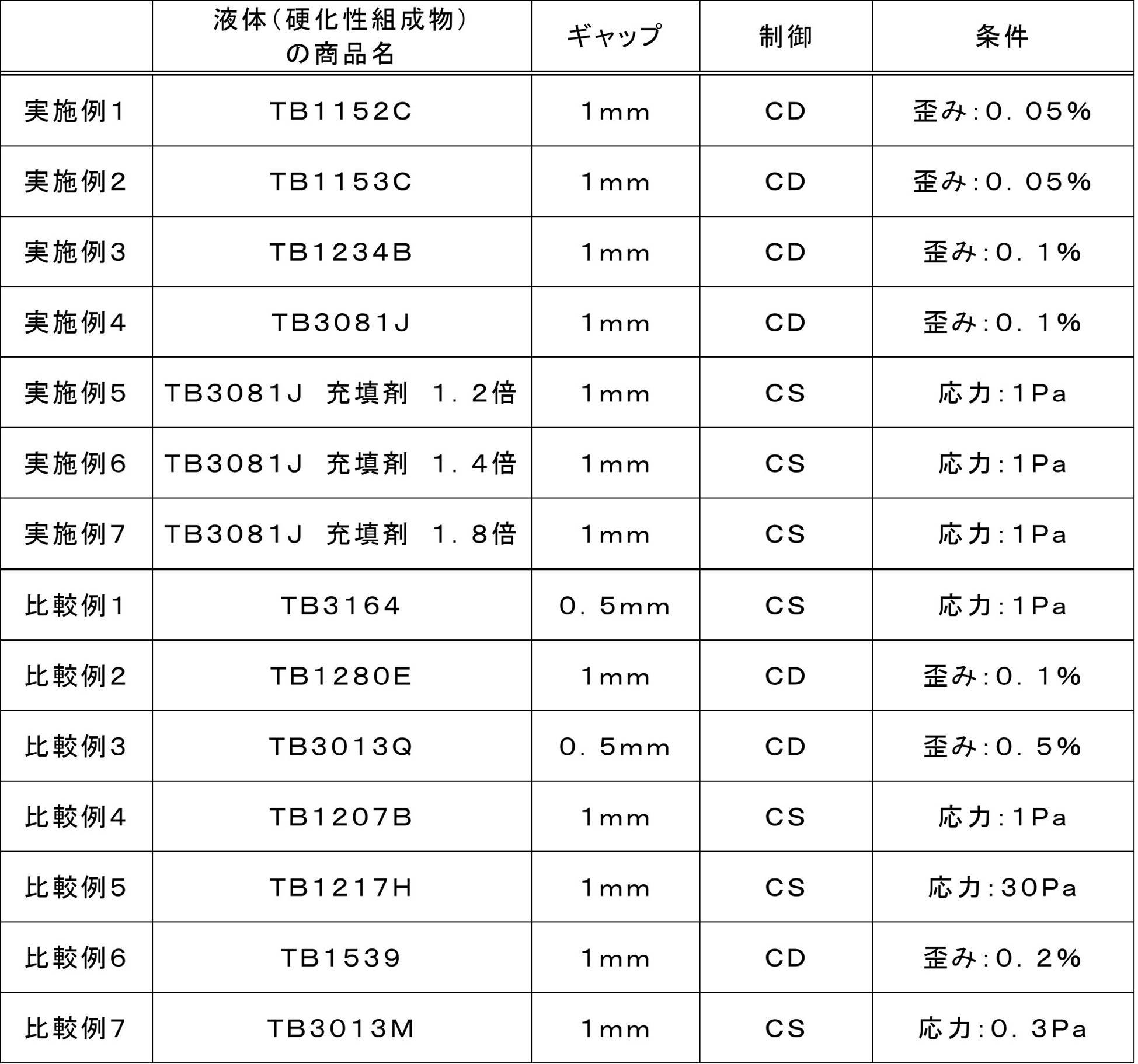
上記表1、2の結果から、実施例1~7の機械発泡用硬化性組成物は、いずれも上記した条件(A)、(B)を充足する複素粘度η*(更には条件(C)のチクソ比)を有することが確認できた。そして、本発明の発泡体の製造方法により得られた実施例1~7の発泡体では、発泡後かつ硬化前の状態の外観及び発泡後かつ硬化後の発泡状態の何れも良好(○評価)であることが確認できた。
一方、上記表1、2の結果から、比較例1~7の硬化性組成物は、上記した条件(A)、(B)を充足する複素粘度η*(更には条件(C)のチクソ比)を有さないもの、硬化形態が湿気硬化性であるものの少なくとも一方に該当するため、いずれも機械発泡に適さない硬化性組成物であることが確認できた。よって、比較例1~7の発泡体では、発泡後かつ硬化前の状態の外観及び発泡後かつ硬化後の発泡状態の何れも不良(×評価)となることがわかった。
本出願は、2018年11月22日に出願された日本国特許出願第2018-219339号に基づいており、その開示内容は、参照により全体として引用されている。
10 機械式発泡装置、 11 流路、
13 吸気口、 21 第1圧力センサー、
22 第2圧力センサー、 100 樹脂供給部(液体供給部)、
200 ポンプ部、 211 第1ギアポンプ、
212 第2ギアポンプ、 220 気体供給部、
230 開閉弁、 240 切り替え弁、
300 ヘッド部、 310 ミキサー、
311 入口部、 312 出口部、
313 混合室、 320 吐出部、
321 ノズル、 322 吐出弁本体部、
331 第1ノズル弁、 332 第2ノズル弁、
400 制御部、 M 発泡体、
M0 発泡性材料、 M1 液体(機械発泡用硬化性組成物)、
M2 気体、 P1 ポンプ間圧力、
P2 吐出圧力、 Pmax 上限圧力、
Pmin 下限圧力、 Pt 目標圧力、
Pc 補正圧力、 Ps 設定圧力。
13 吸気口、 21 第1圧力センサー、
22 第2圧力センサー、 100 樹脂供給部(液体供給部)、
200 ポンプ部、 211 第1ギアポンプ、
212 第2ギアポンプ、 220 気体供給部、
230 開閉弁、 240 切り替え弁、
300 ヘッド部、 310 ミキサー、
311 入口部、 312 出口部、
313 混合室、 320 吐出部、
321 ノズル、 322 吐出弁本体部、
331 第1ノズル弁、 332 第2ノズル弁、
400 制御部、 M 発泡体、
M0 発泡性材料、 M1 液体(機械発泡用硬化性組成物)、
M2 気体、 P1 ポンプ間圧力、
P2 吐出圧力、 Pmax 上限圧力、
Pmin 下限圧力、 Pt 目標圧力、
Pc 補正圧力、 Ps 設定圧力。
Claims (8)
- レオメーターによる周波数依存性測定において、下記の条件(A)および(B)を充足する複素粘度η*を有する機械発泡用硬化性組成物であり、当該機械発泡用硬化性組成物の硬化形態が湿気硬化性ではないことを特徴とする機械発泡用硬化性組成物:
条件(A):25℃で0.1Hzにおけるη*が1000~50000Pa・sの範囲であり、
条件(B):25℃で10.0Hzにおけるη*が100~1000Pa・sの範囲である。 - さらに、下記の条件(C)を充足することを特徴とする請求項1に記載の機械発泡用硬化性組成物:
条件(C):25℃で(0.1Hzにおけるη*)/(10.0Hzにおけるη*)が70.0以下の範囲である。 - 前記条件(A)および(B)におけるη*が、それぞれ1000~30000Pa・sおよび100~900Pa・sであることを特徴とする請求項1または2に記載の機械発泡用硬化性組成物。
- 前記条件(C)におけるη*(0.1Hz)/η*(10.0Hz)が、5.0~50であることを特徴とする請求項2または3に記載の機械発泡用硬化性組成物。
- 整泡剤を含まないことを特徴とする請求項1~4のいずれか1項に記載の機械発泡用硬化性組成物。
- 硬化性組成物の硬化形態が、室温硬化性、熱硬化性および光硬化性よりなる群から選択される少なくとも一つであることを特徴とする請求項1~5のいずれか1項に記載の機械発泡用硬化性組成物。
- ビニル基および環状エーテル基よりなる群から選択される少なくとも一つの反応性官能基を有する樹脂を含むことを特徴とする請求項1~6のいずれか1項に記載の機械発泡用硬化性組成物。
- 液体に気体が混入した発泡性材料を生成し、当該発泡性材料を吐出して発泡させる機械式発泡装置を用いる発泡体の製造方法であって、
前記機械式発泡装置は、
前記液体および前記気体を送出する流路と、
前記流路へ前記液体を供給する液体供給部と、
前記流路へ前記気体を供給する気体供給部と、
前記流路と前記気体供給部との間の連通状態を切り替え可能な開閉弁と、
前記流路の途中に配置された第1ギアポンプと、
前記第1ギアポンプよりも前記流路の下流側に配置され、前記第1ギアポンプよりも高速で回転駆動されることによって前記流路中に前記気体を混入させて前記発泡性材料を生成する吸引圧を発生させる第2ギアポンプと、
前記第1ギアポンプと前記第2ギアポンプとの間における前記流路内のポンプ間圧力を検出する第1圧力センサーと、
前記液体に前記気体が混入した前記発泡性材料を吐出する吐出口を有するノズルと、前記第2ギアポンプから送出された前記発泡性材料を前記ノズルまで送出する連通路を有する吐出弁本体部と、を備える吐出部と、
前記第1ギアポンプ、前記第2ギアポンプ、および前記気体供給部を駆動するとともに前記開閉弁を開いて前記吐出部から前記発泡性材料を吐出する吐出動作と、前記第1ギアポンプ、前記第2ギアポンプ、および前記気体供給部の作動を停止させるとともに前記開閉弁を閉じて前記発泡性材料の吐出を中断させる待機動作とを行うように装置各部を制御する制御部と、を有し、
前記制御部は、前記待機動作中において、前記ポンプ間圧力が予め設定した上限圧力になったとき、前記第2ギアポンプを回転駆動して前記第1ギアポンプと前記第2ギアポンプとの間における前記流路内の前記発泡性材料の少なくとも一部を前記第2ギアポンプの下流側に送出して前記流路内の圧力を前記上限圧力よりも低い圧力に低下させる、機械式発泡装置であり、
前記液体は、請求項1~7のいずれか1項に記載の機械発泡用硬化性組成物であることを特徴とする発泡体の製造方法。
Priority Applications (5)
| Application Number | Priority Date | Filing Date | Title |
|---|---|---|---|
| EP19887293.9A EP3885399A4 (en) | 2018-11-22 | 2019-11-07 | CURABLE COMPOSITION FOR MECHANICAL FOAMING AND METHOD OF MAKING FOAM THEREOF |
| JP2020558262A JP7401784B2 (ja) | 2018-11-22 | 2019-11-07 | 機械発泡用硬化性組成物およびその発泡体の製造方法 |
| US17/295,431 US20220355517A1 (en) | 2018-11-22 | 2019-11-07 | Curable composition for mechanical foaming and method for manufacturing foam of the same |
| PH12021551027A PH12021551027A1 (en) | 2018-11-22 | 2021-05-04 | Curable composition for mechanical foaming and method for manufacturing foam of the same |
| US18/985,358 US20250114986A1 (en) | 2018-11-22 | 2024-12-18 | Curable composition for mechanical foaming and method for manufacturing foam of the same |
Applications Claiming Priority (2)
| Application Number | Priority Date | Filing Date | Title |
|---|---|---|---|
| JP2018-219339 | 2018-11-22 | ||
| JP2018219339 | 2018-11-22 |
Related Child Applications (2)
| Application Number | Title | Priority Date | Filing Date |
|---|---|---|---|
| US17/295,431 A-371-Of-International US20220355517A1 (en) | 2018-11-22 | 2019-11-07 | Curable composition for mechanical foaming and method for manufacturing foam of the same |
| US18/985,358 Division US20250114986A1 (en) | 2018-11-22 | 2024-12-18 | Curable composition for mechanical foaming and method for manufacturing foam of the same |
Publications (1)
| Publication Number | Publication Date |
|---|---|
| WO2020105460A1 true WO2020105460A1 (ja) | 2020-05-28 |
Family
ID=70774471
Family Applications (1)
| Application Number | Title | Priority Date | Filing Date |
|---|---|---|---|
| PCT/JP2019/043738 Ceased WO2020105460A1 (ja) | 2018-11-22 | 2019-11-07 | 機械発泡用硬化性組成物およびその発泡体の製造方法 |
Country Status (5)
| Country | Link |
|---|---|
| US (2) | US20220355517A1 (ja) |
| EP (1) | EP3885399A4 (ja) |
| JP (1) | JP7401784B2 (ja) |
| PH (1) | PH12021551027A1 (ja) |
| WO (1) | WO2020105460A1 (ja) |
Cited By (3)
| Publication number | Priority date | Publication date | Assignee | Title |
|---|---|---|---|---|
| JP2022147672A (ja) * | 2021-03-23 | 2022-10-06 | サンスター技研株式会社 | 光硬化性組成物、光硬化性発泡組成物、ウレタン(メタ)アクリレート化合物、及び発泡体の製造方法 |
| TWI823509B (zh) * | 2022-08-04 | 2023-11-21 | 磐采股份有限公司 | 可發泡樹脂組成物 |
| EP4257231A4 (en) * | 2020-12-03 | 2024-08-28 | ThreeBond Co., Ltd. | Foaming device, and foaming method |
Families Citing this family (1)
| Publication number | Priority date | Publication date | Assignee | Title |
|---|---|---|---|---|
| JP2025537347A (ja) * | 2022-11-22 | 2025-11-14 | ノードソン コーポレーション | 熱交換器を実装するホットメルト接着剤発泡体吐出システム及びホットメルト接着剤発泡体吐出システムを実施する方法 |
Citations (7)
| Publication number | Priority date | Publication date | Assignee | Title |
|---|---|---|---|---|
| JPS61133201A (ja) | 1984-11-30 | 1986-06-20 | Sunstar Giken Kk | 室温硬化性弾性組成物 |
| JP2000038404A (ja) | 1998-07-23 | 2000-02-08 | Kanegafuchi Chem Ind Co Ltd | 末端にアルケニル基を有する重合体の製造方法及び該重合体を用いた硬化性組成物 |
| JP2001271055A (ja) | 2000-03-27 | 2001-10-02 | Kanegafuchi Chem Ind Co Ltd | シーリング材組成物 |
| JP2002069121A (ja) | 2000-08-25 | 2002-03-08 | Kanegafuchi Chem Ind Co Ltd | ビニル系重合体の精製方法 |
| WO2004060628A1 (ja) | 2003-01-07 | 2004-07-22 | Sunstar Giken Kabushiki Kaisha | 機械発泡装置に用いる一液型硬化性ペースト材料 |
| JP2010039358A (ja) * | 2008-08-07 | 2010-02-18 | Canon Inc | 画像形成装置に着脱可能なカートリッジ |
| JP2017109192A (ja) * | 2015-12-18 | 2017-06-22 | 株式会社スリーボンド | 機械式発泡装置および機械式発泡方法 |
Family Cites Families (2)
| Publication number | Priority date | Publication date | Assignee | Title |
|---|---|---|---|---|
| FR2886644B1 (fr) * | 2005-06-01 | 2008-04-18 | Arkema Sa | Utilisation d'une composition particuliere pour la fabrication de pieces par enroulement filamentaire |
| DE102014116389A1 (de) * | 2014-11-11 | 2016-05-12 | Voco Gmbh | Radikalisch härtbare dentale Zusammensetzungen |
-
2019
- 2019-11-07 WO PCT/JP2019/043738 patent/WO2020105460A1/ja not_active Ceased
- 2019-11-07 EP EP19887293.9A patent/EP3885399A4/en active Pending
- 2019-11-07 JP JP2020558262A patent/JP7401784B2/ja active Active
- 2019-11-07 US US17/295,431 patent/US20220355517A1/en not_active Abandoned
-
2021
- 2021-05-04 PH PH12021551027A patent/PH12021551027A1/en unknown
-
2024
- 2024-12-18 US US18/985,358 patent/US20250114986A1/en active Pending
Patent Citations (7)
| Publication number | Priority date | Publication date | Assignee | Title |
|---|---|---|---|---|
| JPS61133201A (ja) | 1984-11-30 | 1986-06-20 | Sunstar Giken Kk | 室温硬化性弾性組成物 |
| JP2000038404A (ja) | 1998-07-23 | 2000-02-08 | Kanegafuchi Chem Ind Co Ltd | 末端にアルケニル基を有する重合体の製造方法及び該重合体を用いた硬化性組成物 |
| JP2001271055A (ja) | 2000-03-27 | 2001-10-02 | Kanegafuchi Chem Ind Co Ltd | シーリング材組成物 |
| JP2002069121A (ja) | 2000-08-25 | 2002-03-08 | Kanegafuchi Chem Ind Co Ltd | ビニル系重合体の精製方法 |
| WO2004060628A1 (ja) | 2003-01-07 | 2004-07-22 | Sunstar Giken Kabushiki Kaisha | 機械発泡装置に用いる一液型硬化性ペースト材料 |
| JP2010039358A (ja) * | 2008-08-07 | 2010-02-18 | Canon Inc | 画像形成装置に着脱可能なカートリッジ |
| JP2017109192A (ja) * | 2015-12-18 | 2017-06-22 | 株式会社スリーボンド | 機械式発泡装置および機械式発泡方法 |
Non-Patent Citations (1)
| Title |
|---|
| See also references of EP3885399A4 |
Cited By (5)
| Publication number | Priority date | Publication date | Assignee | Title |
|---|---|---|---|---|
| EP4257231A4 (en) * | 2020-12-03 | 2024-08-28 | ThreeBond Co., Ltd. | Foaming device, and foaming method |
| US12589369B2 (en) | 2020-12-03 | 2026-03-31 | Threebond Co., Ltd. | Foaming apparatus and foaming method |
| JP2022147672A (ja) * | 2021-03-23 | 2022-10-06 | サンスター技研株式会社 | 光硬化性組成物、光硬化性発泡組成物、ウレタン(メタ)アクリレート化合物、及び発泡体の製造方法 |
| JP7620461B2 (ja) | 2021-03-23 | 2025-01-23 | サンスター技研株式会社 | 光硬化性組成物、光硬化性発泡組成物、ウレタン(メタ)アクリレート化合物、及び発泡体の製造方法 |
| TWI823509B (zh) * | 2022-08-04 | 2023-11-21 | 磐采股份有限公司 | 可發泡樹脂組成物 |
Also Published As
| Publication number | Publication date |
|---|---|
| US20250114986A1 (en) | 2025-04-10 |
| EP3885399A1 (en) | 2021-09-29 |
| EP3885399A4 (en) | 2022-08-10 |
| US20220355517A1 (en) | 2022-11-10 |
| JP7401784B2 (ja) | 2023-12-20 |
| PH12021551027A1 (en) | 2022-02-21 |
| JPWO2020105460A1 (ja) | 2021-10-21 |
Similar Documents
| Publication | Publication Date | Title |
|---|---|---|
| US20250114986A1 (en) | Curable composition for mechanical foaming and method for manufacturing foam of the same | |
| JP6003906B2 (ja) | 光学用光硬化性シート型接着剤組成物 | |
| TW201602148A (zh) | 可固化聚胺基甲酸酯(甲基)丙烯酸酯聚合物組成物及方法 | |
| JP2003105320A (ja) | 精密機器用液状ガスケット材料およびそれを用いた精密機器用ガスケットの製造方法 | |
| WO2002072724A1 (en) | Automotive adhesive | |
| JP2016109997A (ja) | 液晶シール剤及びそれを用いた液晶表示セル | |
| JP6510790B2 (ja) | 光湿気硬化型樹脂組成物 | |
| WO2021230373A1 (ja) | 光湿気硬化型樹脂組成物、電子部品用接着剤、硬化体、及び電子部品 | |
| WO2021157624A1 (ja) | 光湿気硬化性樹脂組成物、電子部品用接着剤、電子部品の製造方法及び硬化体 | |
| JP6846242B2 (ja) | シール部材及びシール部材の製造方法 | |
| WO2020249752A1 (en) | Thermally expandable compositions comprising a chemical blowing agent | |
| JP2018036469A (ja) | 液晶シール剤及びそれを用いた液晶表示セル | |
| JP6735654B2 (ja) | シール部材および、シール部材製造方法 | |
| JP2018178133A (ja) | 硬化性組成物 | |
| CN116731656A (zh) | 液晶滴注法用液晶密封剂和使用该液晶滴注法用液晶密封剂得到的液晶显示面板 | |
| CN104968701B (zh) | 用于电缆接合的非异氰酸酯密封剂 | |
| JP7824194B2 (ja) | 液晶滴下工法用液晶シール剤及びそれを用いた液晶表示セル | |
| KR102763793B1 (ko) | 엘라스토머성 조성물 및 사용 방법 | |
| JPWO2019203277A1 (ja) | 硬化性樹脂組成物、硬化体、電子部品及び組立部品 | |
| JP2005002309A (ja) | 2剤型反応性ホットメルト硬化性組成物及びその製造方法並びに混合方法 | |
| JP2008179689A (ja) | ガラス用接着剤組成物 | |
| JP2025082855A (ja) | 液晶滴下工法用液晶シール剤及びそれを用いた液晶表示パネル | |
| JP2025150199A (ja) | 液晶滴下工法用液晶シール剤の製造方法、及び液晶表示パネルの製造方法 | |
| CN109906260B (zh) | 密封构件和密封构件的制造方法 | |
| KR20250029803A (ko) | 광 습기 경화형 수지 조성물, 경화물, 광 습기 경화형 수지 조성물의 사용, 및 단면 보호 방법 |
Legal Events
| Date | Code | Title | Description |
|---|---|---|---|
| 121 | Ep: the epo has been informed by wipo that ep was designated in this application |
Ref document number: 19887293 Country of ref document: EP Kind code of ref document: A1 |
|
| ENP | Entry into the national phase |
Ref document number: 2020558262 Country of ref document: JP Kind code of ref document: A |
|
| NENP | Non-entry into the national phase |
Ref country code: DE |
|
| ENP | Entry into the national phase |
Ref document number: 2019887293 Country of ref document: EP Effective date: 20210622 |