WO2020105603A1 - 金属化合物粒子群、蓄電デバイス用電極、蓄電デバイス、および金属化合物粒子群の製造方法 - Google Patents
金属化合物粒子群、蓄電デバイス用電極、蓄電デバイス、および金属化合物粒子群の製造方法Info
- Publication number
- WO2020105603A1 WO2020105603A1 PCT/JP2019/045151 JP2019045151W WO2020105603A1 WO 2020105603 A1 WO2020105603 A1 WO 2020105603A1 JP 2019045151 W JP2019045151 W JP 2019045151W WO 2020105603 A1 WO2020105603 A1 WO 2020105603A1
- Authority
- WO
- WIPO (PCT)
- Prior art keywords
- metal compound
- particle group
- compound particle
- silicon oxide
- coupling agent
- Prior art date
- Legal status (The legal status is an assumption and is not a legal conclusion. Google has not performed a legal analysis and makes no representation as to the accuracy of the status listed.)
- Ceased
Links
Images







Classifications
-
- H—ELECTRICITY
- H01—ELECTRIC ELEMENTS
- H01M—PROCESSES OR MEANS, e.g. BATTERIES, FOR THE DIRECT CONVERSION OF CHEMICAL ENERGY INTO ELECTRICAL ENERGY
- H01M4/00—Electrodes
- H01M4/02—Electrodes composed of, or comprising, active material
- H01M4/36—Selection of substances as active materials, active masses, active liquids
- H01M4/48—Selection of substances as active materials, active masses, active liquids of inorganic oxides or hydroxides
-
- H—ELECTRICITY
- H01—ELECTRIC ELEMENTS
- H01G—CAPACITORS; CAPACITORS, RECTIFIERS, DETECTORS, SWITCHING DEVICES, LIGHT-SENSITIVE OR TEMPERATURE-SENSITIVE DEVICES OF THE ELECTROLYTIC TYPE
- H01G11/00—Hybrid capacitors, i.e. capacitors having different positive and negative electrodes; Electric double-layer [EDL] capacitors; Processes for the manufacture thereof or of parts thereof
- H01G11/04—Hybrid capacitors
- H01G11/06—Hybrid capacitors with one of the electrodes allowing ions to be reversibly doped thereinto, e.g. lithium ion capacitors [LIC]
-
- H—ELECTRICITY
- H01—ELECTRIC ELEMENTS
- H01G—CAPACITORS; CAPACITORS, RECTIFIERS, DETECTORS, SWITCHING DEVICES, LIGHT-SENSITIVE OR TEMPERATURE-SENSITIVE DEVICES OF THE ELECTROLYTIC TYPE
- H01G11/00—Hybrid capacitors, i.e. capacitors having different positive and negative electrodes; Electric double-layer [EDL] capacitors; Processes for the manufacture thereof or of parts thereof
- H01G11/22—Electrodes
- H01G11/24—Electrodes characterised by structural features of the materials making up or comprised in the electrodes, e.g. form, surface area or porosity; characterised by the structural features of powders or particles used therefor
-
- H—ELECTRICITY
- H01—ELECTRIC ELEMENTS
- H01G—CAPACITORS; CAPACITORS, RECTIFIERS, DETECTORS, SWITCHING DEVICES, LIGHT-SENSITIVE OR TEMPERATURE-SENSITIVE DEVICES OF THE ELECTROLYTIC TYPE
- H01G11/00—Hybrid capacitors, i.e. capacitors having different positive and negative electrodes; Electric double-layer [EDL] capacitors; Processes for the manufacture thereof or of parts thereof
- H01G11/54—Electrolytes
- H01G11/58—Liquid electrolytes
- H01G11/62—Liquid electrolytes characterised by the solute, e.g. salts, anions or cations therein
-
- H—ELECTRICITY
- H01—ELECTRIC ELEMENTS
- H01M—PROCESSES OR MEANS, e.g. BATTERIES, FOR THE DIRECT CONVERSION OF CHEMICAL ENERGY INTO ELECTRICAL ENERGY
- H01M10/00—Secondary cells; Manufacture thereof
- H01M10/05—Accumulators with non-aqueous electrolyte
- H01M10/052—Li-accumulators
- H01M10/0525—Rocking-chair batteries, i.e. batteries with lithium insertion or intercalation in both electrodes; Lithium-ion batteries
-
- H—ELECTRICITY
- H01—ELECTRIC ELEMENTS
- H01M—PROCESSES OR MEANS, e.g. BATTERIES, FOR THE DIRECT CONVERSION OF CHEMICAL ENERGY INTO ELECTRICAL ENERGY
- H01M4/00—Electrodes
- H01M4/02—Electrodes composed of, or comprising, active material
- H01M4/04—Processes of manufacture in general
- H01M4/0471—Processes of manufacture in general involving thermal treatment, e.g. firing, sintering, backing particulate active material, thermal decomposition, pyrolysis
-
- H—ELECTRICITY
- H01—ELECTRIC ELEMENTS
- H01M—PROCESSES OR MEANS, e.g. BATTERIES, FOR THE DIRECT CONVERSION OF CHEMICAL ENERGY INTO ELECTRICAL ENERGY
- H01M4/00—Electrodes
- H01M4/02—Electrodes composed of, or comprising, active material
- H01M4/13—Electrodes for accumulators with non-aqueous electrolyte, e.g. for lithium-accumulators; Processes of manufacture thereof
- H01M4/139—Processes of manufacture
- H01M4/1391—Processes of manufacture of electrodes based on mixed oxides or hydroxides, or on mixtures of oxides or hydroxides, e.g. LiCoOx
-
- H—ELECTRICITY
- H01—ELECTRIC ELEMENTS
- H01M—PROCESSES OR MEANS, e.g. BATTERIES, FOR THE DIRECT CONVERSION OF CHEMICAL ENERGY INTO ELECTRICAL ENERGY
- H01M4/00—Electrodes
- H01M4/02—Electrodes composed of, or comprising, active material
- H01M4/36—Selection of substances as active materials, active masses, active liquids
- H01M4/362—Composites
- H01M4/366—Composites as layered products
-
- H—ELECTRICITY
- H01—ELECTRIC ELEMENTS
- H01M—PROCESSES OR MEANS, e.g. BATTERIES, FOR THE DIRECT CONVERSION OF CHEMICAL ENERGY INTO ELECTRICAL ENERGY
- H01M4/00—Electrodes
- H01M4/02—Electrodes composed of, or comprising, active material
- H01M4/36—Selection of substances as active materials, active masses, active liquids
- H01M4/48—Selection of substances as active materials, active masses, active liquids of inorganic oxides or hydroxides
- H01M4/485—Selection of substances as active materials, active masses, active liquids of inorganic oxides or hydroxides of mixed oxides or hydroxides for inserting or intercalating light metals, e.g. LiTi2O4 or LiTi2OxFy
-
- H—ELECTRICITY
- H01—ELECTRIC ELEMENTS
- H01M—PROCESSES OR MEANS, e.g. BATTERIES, FOR THE DIRECT CONVERSION OF CHEMICAL ENERGY INTO ELECTRICAL ENERGY
- H01M4/00—Electrodes
- H01M4/02—Electrodes composed of, or comprising, active material
- H01M4/62—Selection of inactive substances as ingredients for active masses, e.g. binders, fillers
-
- H—ELECTRICITY
- H01—ELECTRIC ELEMENTS
- H01M—PROCESSES OR MEANS, e.g. BATTERIES, FOR THE DIRECT CONVERSION OF CHEMICAL ENERGY INTO ELECTRICAL ENERGY
- H01M4/00—Electrodes
- H01M4/02—Electrodes composed of, or comprising, active material
- H01M2004/021—Physical characteristics, e.g. porosity, surface area
-
- H—ELECTRICITY
- H01—ELECTRIC ELEMENTS
- H01M—PROCESSES OR MEANS, e.g. BATTERIES, FOR THE DIRECT CONVERSION OF CHEMICAL ENERGY INTO ELECTRICAL ENERGY
- H01M4/00—Electrodes
- H01M4/02—Electrodes composed of, or comprising, active material
- H01M2004/026—Electrodes composed of, or comprising, active material characterised by the polarity
- H01M2004/028—Positive electrodes
-
- Y—GENERAL TAGGING OF NEW TECHNOLOGICAL DEVELOPMENTS; GENERAL TAGGING OF CROSS-SECTIONAL TECHNOLOGIES SPANNING OVER SEVERAL SECTIONS OF THE IPC; TECHNICAL SUBJECTS COVERED BY FORMER USPC CROSS-REFERENCE ART COLLECTIONS [XRACs] AND DIGESTS
- Y02—TECHNOLOGIES OR APPLICATIONS FOR MITIGATION OR ADAPTATION AGAINST CLIMATE CHANGE
- Y02E—REDUCTION OF GREENHOUSE GAS [GHG] EMISSIONS, RELATED TO ENERGY GENERATION, TRANSMISSION OR DISTRIBUTION
- Y02E60/00—Enabling technologies; Technologies with a potential or indirect contribution to GHG emissions mitigation
- Y02E60/10—Energy storage using batteries
Definitions
- the present invention relates to a metal compound particle group, an electrode for an electricity storage device, an electricity storage device, and a method for producing a metal compound particle group.
- the electrode of the secondary battery has a positive electrode and a negative electrode containing an active material that reversibly absorbs and desorbs lithium ions, and an electrolyte solution in which a lithium salt is dissolved.
- lithium ions are discharged from the positive electrode and stored in the negative electrode by charging and discharging, and lithium ions are discharged from the negative electrode and stored in the positive electrode by discharging.
- the lithium ion secondary battery has the advantages that it can operate at high voltage and has a large energy density.
- the hybrid capacitor has a polarizable electrode having an electric double layer capacity as a positive electrode, a metal compound particle capable of inserting and extracting lithium as a negative electrode, and has the advantages of a lithium ion secondary battery and an electric double layer capacitor. That is, this hybrid capacitor has high energy density and high input / output characteristics.
- an object of the present invention is to provide a metal compound particle group capable of suppressing an increase in internal resistance of an electricity storage device, an electrode for an electricity storage device including the metal compound particle group, and a method for producing the metal compound particle group. is there.
- the metallic compound particle group concerning this embodiment has the following composition.
- the coating layer containing the silicon oxide may be formed on at least a part of the surface of the metal compound particles.
- the amount of Si element may be 0.4 or more and 3.0 wt% or less with respect to the entire metal compound particle group.
- Voids may be present in the three-dimensional network structure, and a coating layer containing the silicon oxide may be formed on the metal compound particles that define the voids.
- the silicon oxide contained in the coating layer may be amorphous silicon oxide.
- the pore volume change rate converted from the pore distribution measured by the nitrogen gas adsorption measurement method for the metal compound particle group which is more than 0.008 dV p / dr p with respect to the pore diameter of 10 nm or less. It may have a pore volume change rate of.
- the reduction rate of the integrated intensity may be 25% or more with respect to the metal compound particle group in which the coating layer containing the silicon oxide is not formed.
- the metal compound particles may be lithium titanate.
- an electrode for a power storage device containing the above-mentioned metal compound particle group It can also be used as an electrode for a power storage device containing the above-mentioned metal compound particle group.
- an electricity storage device having an element having a negative electrode, which is an electrode for an electricity storage device, and a positive electrode, and an electrolytic solution impregnated in the element, and the electrolytic solution containing a fluorine-containing compound can also be provided.
- the method for producing the metal compound particle group of the present embodiment includes a mixing step of mixing the metal compound particle group serving as a base and a silicon oxide raw material, and heating the powder obtained by the mixing step at 300 to 600 ° C. And a heating step to perform.
- the raw material of the silicon oxide may be mixed in a ratio of 1 to 20 wt% with respect to the weight of the base metal compound particle group.
- the raw material of the silicon oxide may be mixed in a ratio of 3 to 20 wt% with respect to the weight of the metal compound particle group serving as the base.
- one kind or two or more kinds of alkaline compounds may be further mixed.
- a pretreatment step of pretreating the base metal compound particle group with an alkali compound may be included.
- the alkali compound include alkali metal or alkaline earth metal hydroxides, acetates, sulfates, carbonates, nitrates, chlorides, inorganic alkali agents or organic alkali agents.
- a metal compound particle group capable of suppressing an increase in internal resistance of an electricity storage device, an electrode for an electricity storage device including the metal compound particle group, and a method for producing the metal compound particle group.
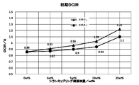
- the result of having measured the initial internal resistance about the lithium ion secondary battery which contained the lithium titanate particle group of the comparative example and the example produced using the silane coupling agent which has an acryloyl group in the active material layer of a negative electrode is shown. It is a graph.
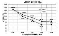
- the increase rate of the internal resistance after 2000 cycles was measured for a lithium ion secondary battery in which the lithium titanate particles of the example prepared using a silane coupling agent having an acryloyl group were included in the active material layer of the negative electrode. It is a graph which shows.
- the results of measuring the initial internal resistance of a lithium ion secondary battery in which the lithium titanate particles of the example prepared using a silane coupling agent having a comparative example and an epoxy group are included in the active material layer of the negative electrode are shown. It is a graph.
- the increase rate of the internal resistance after 2000 cycles was measured. It is a graph which shows the measured result.
- FIG. 5 is a graph showing the results of measuring the initial internal resistance of a lithium ion secondary battery in which the lithium titanate particle groups of the comparative example and the example prepared while adding an alkaline compound were included in the active material layer of the negative electrode.
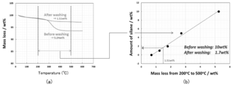
- the result of measuring the increase rate of the internal resistance after 2000 cycles of the lithium ion secondary battery in which the lithium titanate particle groups of the comparative example and the example prepared by adding the alkali compound were included in the active material layer of the negative electrode is shown. It is a graph. It is a graph which shows the result of having performed the thermogravimetric measurement about the lithium titanate particle group of a comparative example, (a) is a graph of the thermogravimetric measurement result, (b) converts the amount of the silane coupling agent from the loss amount.
- the metal compound particle group is mainly used for an electrode of an electricity storage device.
- the metal compound particles forming the metal compound particle group are materials that can operate as a positive electrode active material or a negative electrode active material of a power storage device such as a lithium ion secondary battery or a lithium ion capacitor.
- the metal compound particle group has a three-dimensional network structure in which nano-sized metal compound particles are connected, and a silicon oxide (SiO x or SiO x (OH) 4-2X (where x is , 0 to 2) is formed.
- the coat layer containing silicon oxide is formed on at least a part of the surface of the metal compound particles.
- the structure has voids, and the metal compound particles defining the voids have a coating layer containing silicon oxide formed on the surface thereof.
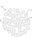
- the metal compound particle group A has a three-dimensional network structure.
- the three-dimensional network structure is a structure in which the primary particles 1 of a metal compound having a nano size are combined and connected in a network form, and a nano size void 2 exists. There is no grain boundary at the bonding interface of the primary particles 1, while many fine pores are present between the primary particles 1.
- the three-dimensional network structure forms an electron path for the negative electrode active material, the voids 2 serve as storage sites for the electrolytic solution, and the pores between the primary particles 1 serve as ion paths.
- the metal compound particles are particles capable of inserting and extracting lithium ions.
- the metal compound particles include FeO, Fe 2 O 3 , Fe 3 O 4 , MnO, MnO 2 , Mn 2 O 3 , Mn 3 O 4 , CoO, Co 3 O 4 , NiO, Ni 2 O 3 , TiO, and TiO 2.
- oxides such as TiO 2 (B), TiNb 2 O 7 , Nb 2 O 5 , CuO, NiO, SnO, SnO 2 , SiO 2 , RuO 2 , WO, WO 2 , WO 3 , MoO 3 , and ZnO, Metals such as Sn, Si, Al, Zn, LiVO 2 , Li 3 VO 4 , Li 4 Ti 5 O 12 , Sc 2 TiO 5 , Fe 2 TiO 5 , Li 2 Na 2 Ti 6 O 14 , Li 2 BaTi 6 O.
- composite oxides such as Li 2 SrTi 6 O 14, nitrides such as Li 2.6 Co 0.4 N, Ge 3 N 4 , Zn 3 N 2 and Cu 3 N, Y 2 Ti 2 O 5 S 2 , MoS 2 .
- the oxide or oxyacid salt containing lithium is represented by Li ⁇ M ⁇ Y ⁇ .
- M Co, Ni, Mn, Ti, Si, Sn, Al, Zn, Mg, Nb, or V
- Y O.
- M Fe, Mn, V, Co, or Ni
- Y PO 4 , SiO 4 , BO 3 , or P 2 O 7 .
- M ′ Fe, Co, Mn, V, Ti, or Ni.
- lithium iron phosphate, lithium titanate, lithium cobalt oxide, lithium vanadium phosphate, lithium iron manganese phosphate can be used.
- lithium titanate Li 4 Ti 5 O 12
- the porosity in the cross section of the three-dimensional network structure is preferably in the range of 7 to 50%.
- the porosity is less than 7%, the area in contact with the electrolytic solution is small, which affects the movement of ions in the electrolytic solution. Further, when the porosity exceeds 50%, the bonds between the primary particles 1 become rough and it becomes difficult to form a three-dimensional network structure.
- the average particle size of the primary particles 1 is in the range of 5 to 300 nm.
- the method of calculating the average particle size is as follows. First, the primary particles 1 are observed using a scanning electron microscope, and an image containing at least 150 primary particles 1 is photographed. The major axis and the minor axis of the elliptical image of the primary particle 1 included in one photographed visual field (image) are measured, and the average value of the major axis and the minor axis is calculated for each primary particle 1. Then, the average value of each primary particle 1 is added, and the added value is divided by the measured number of primary particles 1. This result falls within the range of 5 to 300 nm.
- the metal compound particles acquire many nano-sized pores.
- the area of the metal compound particles in contact with the electrolytic solution increases, and the movement of ions in the electrolytic solution becomes smooth.
- the pores of the metal compound particles were measured, many fine pores were present. In particular, it includes many fine pores of 40 nm or less.
- the differential pore volume was converted from the pore distribution measured by the nitrogen gas adsorption measurement method.
- the differential pore volume in the pore diameter range of 10 to 40 nm has a value of 0.01 cm 3 / g or more, and particularly a value of 0.02 cm 3 / g or more is obtained. Therefore, the larger the area in contact with the electrolytic solution and the larger the area in contact with the electrolytic solution, the better the discharge rate characteristic when used in the negative electrode.
- the coat layer C is formed on a part of the metal compound particle group A.
- the metal compound particles are preferably formed on at least a part of the surface.
- the coat layer C is a layer containing silicon oxide.
- the coat layer C may be formed on the surface of the metal compound particles that define the voids 2 of the metal compound particle group A. That is, the coat layer C may be formed not only on the outer peripheral surface side of the metal compound particle group A but also on the surface of the metal compound particles in the voids 2 in the internal structure of the metal compound particle group A. However, the coat layer C is not formed so as to fill the voids 2, and the voids 2 remain in the metal compound particle group A in which the coat layer C is formed.
- Such a metal compound particle group A has a pore volume change rate of more than 0.008 dV p / dr p for a pore size of 10 nm or less. Further, the metal compound particle group A in which the coating layer C containing silicon oxide is formed has a reduction rate of the integrated intensity of 25 with respect to the metal compound particle group in which the coating layer C containing silicon oxide is not formed. % Or more.
- the coating layer C is preferably formed such that the content of the Si element in the metal compound particle group A is 0.4 or more and 3.0 wt% or less.
- the increase rate of the internal resistance after that can be suitably suppressed. If it exceeds 3.0 wt%, the coating layer is excessive for suppressing the generation of deposits, and it is not possible to expect a further suppression effect of the increase rate of the internal resistance.
- the silicon oxide contained in the coat layer C has low crystallinity. That is, silicon oxide is amorphous and does not have a perfect crystal structure. It is considered that such an amorphous silicon oxide has a good bonding property with the metal compound particles. Therefore, the coat layer C containing the amorphous silicon oxide is not locally formed on the surface of the metal compound particles. That is, the surface of the metal compound particles is formed uniformly and clinging to the metal compound particles. Although the bonding state between silicon oxide and metal compound particles has not been analyzed, it is likely that the surface functional group of the metal compound particle and the silicon oxide are bonded by physical adsorption such as hydrogen adsorption or the surface functional group of the metal compound particle and silicon oxide. It is considered to be a chemical bond with the surface functional group of the product.
- the coat layer C contains about 1% or less of carbon in addition to silicon oxide. Therefore, it is presumed that the coat layer C contains a carbon compound or a component such as SiOC n H 2n + 1 or SiC.
- the metal compound particle group A as described above is used as an electrode material for a power storage device such as a hybrid capacitor or a lithium ion secondary battery.
- a power storage device such as a hybrid capacitor or a lithium ion secondary battery.
- the configuration of the hybrid capacitor using the metal compound particle group A of the present embodiment will be described below as an example.
- a lithium ion secondary battery is an example of a power storage device.
- a positive electrode and a negative electrode are opposed to each other via a separator to form an element, and the element is impregnated with an electrolytic solution.
- the lithium ion secondary battery is charged and discharged according to the direction of occlusion and release of lithium ions in the positive and negative electrodes.
- Each of the positive electrode and the negative electrode is formed by integrating a layer of an active material with a current collector.
- the positive electrode active material and the current collector, and the negative electrode active material and the current collector are bonded to each other via a binder using a pressure bonding method or a doctor blade method.
- the current collector is typically a conductive material such as aluminum, copper, iron, nickel, titanium, steel, or carbon. Particularly, aluminum or copper having high thermal conductivity and electronic conductivity is preferable.
- shape of the current collector any shape such as a film shape, a foil shape, a plate shape, a net shape, an expanded metal shape, and a cylindrical shape can be adopted.
- binder examples include rubbers such as fluorine rubber, diene rubber, and styrene rubber, fluoropolymers such as polytetrafluoroethylene and polyvinylidene fluoride, cellulose such as carboxymethyl cellulose and nitrocellulose, and other polyolefin resins, polyimide Examples thereof include resins, acrylic resins, nitrile resins, polyester resins, phenol resins, polyvinyl acetate resins, polyvinyl alcohol resins, epoxy resins and the like. These binders may be used alone or in combination of two or more.
- the positive electrode active material layer is formed by kneading LMO particles, carbon which is a conductive auxiliary agent, and a binder, and is combined with a current collector.
- the carbon can be used without particular limitation as long as it has conductivity, for example, Ketjen black, acetylene black, carbon black such as channel black, fullerene, carbon nanotubes, carbon nanofibers, amorphous carbon, carbon fibers, Examples thereof include natural graphite, artificial graphite, graphitized Ketjen black, mesoporous carbon, vapor grown carbon fiber and the like.
- binder known binders such as polytetrafluoroethylene, polyvinylidene fluoride (PVDF), tetrafluoroethylene-hexafluoropropylene copolymer, polyvinyl fluoride and carboxymethyl cellulose are used.
- the content of the binder is preferably 1 or more and 30 mass% or less with respect to the total amount of the electrode material.
- positive electrode active material may be added to this positive electrode active material layer.
- Other positive electrode active materials include layered rock salt type LiMO 2 , layered Li 2 MnO 3 -LiMO 2 solid solution, and spinel type LiM 2 O 4 (M in the formula is Fe, Co, Ni, a combination thereof, or a combination thereof. And Mn).
- positive electrode active materials other than the above include sulfur and sulfides such as Li 2 S, TiS 2 , MoS 2 , FeS 2 , VS 2 , Cr 1/2 V 1/2 S 2 , NbSe 3 , VSe 2 , In addition to selenides such as NbSe 3, oxides such as Cr 2 O 5 , Cr 3 O 8 , VO 2 , V 3 O 8 , V 2 O 5 , and V 6 O 13 , LiNi 0.8 Co 0.15 Al.
- sulfur and sulfides such as Li 2 S, TiS 2 , MoS 2 , FeS 2 , VS 2 , Cr 1/2 V 1/2 S 2 , NbSe 3 , VSe 2 .
- selenides such as NbSe 3
- oxides such as Cr 2 O 5 , Cr 3 O 8 , VO 2 , V 3 O 8 , V 2 O 5 , and V 6 O 13 , LiNi 0.8 Co 0.15 Al.
- the negative electrode active material is the above-mentioned metal compound particle group A, which is a metal compound particle group capable of inserting and extracting lithium ions.
- metal compound particle group A which is a metal compound particle group capable of inserting and extracting lithium ions.
- lithium titanate has an energy storage function by inserting / desorbing lithium ions. Since the volume change due to insertion / removal is about 1%, there is little capacity deterioration. Since the charge / discharge potential is about 1.55 V (vs. Li / Li +), side reactions such as decomposition of the electrolytic solution and precipitation of lithium metal due to rapid charge / discharge do not easily occur, and the cycle characteristics are excellent.
- Examples of the base separator include kraft, Manila hemp, esparto, hemp, rayon and other celluloses and their mixed papers, polyethylene terephthalate, polybutylene terephthalate, polyethylene naphthalate, polyester resins such as their derivatives, and polytetrafluoroethylene.
- -Based resin polyvinylidene fluoride-based resin, vinylon-based resin, aliphatic polyamide, semi-aromatic polyamide, polyamide-based resin such as wholly aromatic polyamide, polyimide-based resin, polyethylene resin, polypropylene resin, trimethylpentene resin, polyphenylene sulfide resin,
- a resin such as an acrylic resin may be used alone or in combination.
- the electrolyte of the electrolytic solution is a lithium salt that serves as a lithium ion source.
- the lithium salt include LiPF 6 , LiBF 4 , LiClO 4 , LiN (SO 2 CF 3 ) 2 , LiN (SO 2 C 2 F 5 ) 2 , CF 3 SO 3 Li, LiC (SO 2 CF 3 ) 3 , and LiPF 3 (C 2 F 5 ) 3 or a mixture thereof.
- the concentration of the lithium salt is generally in the range of 0.1 to 2.5 mol / L, preferably 0.5 to 2 mol / L.
- a quaternary ammonium salt may be added in addition to the lithium salt.
- the quaternary ammonium salt is added at a molar concentration of 1.6 M or more, but is not particularly limited, but is added at a molar concentration of 1 M, for example.
- Examples of the quaternary ammonium salt include tetraethylammonium, triethylmethylammonium, diethyldimethylammonium, ethyltrimethylammonium, methylethylpyrrolidinium, spirobipyrrolidinium, spiro- (N, N ′)-bipyrrolidinium and 1-ethyl as a cation.
- Examples thereof include -3-methylimidazolium, 1-ethyl-2,3-dimethylimidazolium, and the like.
- Anions include BF 4 ⁇ , PF 6 ⁇ , ClO 4 ⁇ , AsF 6 ⁇ , SbF 6 ⁇ , AlCl. 4 -, or RfSO 3 -, (RfSO 2) 2 N -, RfCO 2 - (Rf is a fluoroalkyl group having 1 to 8 carbon atoms), and the like.
- the following solvents are used as the electrolyte solvent. These solvents may be used alone or in combination of two or more. Examples thereof include cyclic carbonic acid ester, chain carbonic acid ester, phosphoric acid ester, cyclic ether, chained ether, lactone compound, chained ester, nitrile compound, amide compound, sulfone compound and the like. Examples of the cyclic carbonic acid ester include ethylene carbonate, propylene carbonate, butylene carbonate, 4-fluoro-1,3-dioxolan-2-one and 4- (trifluoromethyl) -1,3-dioxolan-2-one. Of these, ethylene carbonate and propylene carbonate are preferable.
- chain carbonic acid ester examples include dimethyl carbonate, ethyl methyl carbonate, diethyl carbonate, methyl n-propyl carbonate, methyl isopropyl carbonate, n-butyl methyl carbonate, diethyl carbonate, ethyl n-propyl carbonate, ethyl isopropyl carbonate, n-butyl ethyl.
- Carbonate, di-n-propyl carbonate, diisopropyl carbonate, di-n-butyl carbonate, fluoroethyl methyl carbonate, difluoroethyl methyl carbonate, trifluoroethyl methyl carbonate and the like can be mentioned, preferably dimethyl carbonate, ethyl methyl carbonate and diethyl carbonate. is there.
- Phosphonates include trimethyl phosphate, triethyl phosphate, ethyl dimethyl phosphate, diethyl methyl phosphate, etc.
- Examples of the cyclic ether include tetrahydrofuran and 2-methyltetrahydrofuran.
- Examples of the chain ether include dimethoxyethane and the like.
- Examples of the lactone compound include ⁇ -valerolactone and ⁇ -butyrolactone.
- Examples of the chain ester include methyl propionate, methyl acetate, ethyl acetate, methyl formate and the like.
- Examples of the nitrile compound include acetonitrile and the like.
- Examples of the amide compound include dimethylformamide.
- Examples of the sulfone compound include, but are not limited to, sulfolane, methylsulfolane, dimethylsulfone, ethylmethylsulfone, and isopropylsulf
- the method for producing a metal compound particle group according to the present invention has the following steps. (1) Mixing step of mixing the base metal compound particle group and the raw material of silicon oxide (2) Heating step of heating the powder obtained by the mixing step at 300 to 600 ° C.
- the metal compound particle group A of this embodiment is created based on the metal compound particle group serving as a base.
- the metal compound particle group serving as a base has a three-dimensional network structure. However, no coat layer was formed on the surface of the metal compound particle group.
- the metal compound particle group A of the present embodiment is manufactured by performing the treatment described in the above steps (1) and (2) using this metal compound particle group. Hereinafter, each step will be described in detail.
- the metal compound particle group serving as the base and the raw material of silicon oxide are mixed to prepare a mixed solution.
- a silane coupling agent containing a silicon atom can be used as a raw material of silicon oxide.
- a solvent is added to a mixture of the base metal compound particle group and the silane coupling agent to prepare a mixed solution.
- the silane coupling agent is preferably mixed in a ratio of 1 to 20 wt%, and more preferably 3 to 20 wt% with respect to the weight of the base metal compound particle group.
- the mixing amount of the silane coupling agent is less than 1 wt%, deposits are remarkably formed on the negative electrode material in the electricity storage device prepared using the metal compound particle group A. Therefore, the effect of suppressing the internal resistance cannot be obtained. Further, when the mixing amount of the silane coupling agent exceeds 20 wt%, the thickness of the coat layer C formed in the electricity storage device prepared using the metal compound particle group A increases.
- the mixing amount of the silane coupling agent is 3 to 20 wt%, the coating process in which the amount of Si element contained in the metal compound particle group A becomes 0.4 to 3.0 wt% by the heating process.
- the layer C is formed, and the increase rate of the internal resistance after charge / discharge can be suitably suppressed.
- the mixing amount of the silane coupling agent is 3 to 10 wt%, the amount of the Si element contained in the metal compound particle group A becomes 0.4 or more and 1.4 wt% or less through the heating process.
- the coat layer C is formed, the thickness of the coat layer C becomes appropriate, and the increase rate of the internal resistance after charging / discharging can be suitably suppressed, and the initial increase of the internal resistance of the electricity storage device can be suppressed.
- the silane coupling agent is not particularly limited, but a silane coupling agent composed of a compound represented by the following general formula or a salt thereof is typical.
- X 1 is an atomic group having a vinyl group, an amino group, an epoxy group, a chloro group, a mercapto group, a ketimine group, an acryloyl group, a methacroyl group, a styryl group, a phenyl group, an isocyanate group, an alkyl group or an alkoxy group.
- X 2 to X 4 are alkyl groups, alkoxy groups, chloro groups, hydroxyl groups)
- These silane coupling agents include tetraethoxysilane, vinyltrimethoxysilane, N- (2-aminoethyl) 3-aminopropyltrimethoxysilane, 3-aminopropyltriethoxysilane, and 3-glycidoxypropyltrimethoxy.
- Silane 2- (3,4-epoxycyclohexyl) ethyltrimethoxysilane, 3-acryloxypropyltrimethoxysilane, 3-methacryloxypropyltrimethoxysilane, 3-mercaptopropyltrimethoxysilane, N- [2- (vinyl Examples thereof include benzylamino) ethyl] -3-aminopropyltrimethoxysilane / hydrochloride.
- any liquid that does not adversely affect the reaction can be used without particular limitation, and water, methanol, ethanol, isopropyl alcohol, etc. can be preferably used. You may mix and use 2 or more types of solvents.
- the prepared mixed solution is sufficiently stirred using a homogenizer so that the metal compound particle group and the silane coupling agent are dispersed in the mixed solution.
- the silane coupling agent is attached to the surfaces and voids of the metal compound particle group serving as the base.
- the mixed solution after stirring is allowed to stand, the metal compound particle group and the silane coupling agent dispersed in the mixed solution are aggregated, and the mixed powder of the metal compound particle group and the silane coupling agent is recovered.
- an alkaline compound may be further added to the mixed solution.
- an alkaline compound By adding an alkaline compound, the amount of silicon oxide deposited relative to the amount of silicon oxide raw material added during the manufacturing process increases, and with a small amount of silane coupling agent added, the rate of increase in internal resistance after charging and discharging is increased. Can be suppressed more suitably.
- the amount of the raw material of the silicon oxide added in the manufacturing process can be reduced, leading to a reduction in cost.
- the reactivity of the metal compound particle group and the silane coupling agent is improved by the catalytic action of the alkali compound, and the silicon oxide is likely to be attached to the surface of the metal compound particle group. Conceivable. Therefore, the amount of silicon oxide attached to the amount of raw material of silicon oxide added in the manufacturing process increases, and the increase rate of internal resistance after charge and discharge is suppressed as compared with the case where no alkali compound is added. it is conceivable that.
- the amount of the alkali compound added is preferably in the range of 0.05 to 5 mmol with respect to 10 g of the metal compound particle group.
- Alkali metals and alkaline earth metals are, for example, lithium, sodium, potassium and calcium.
- examples of the inorganic alkaline agent include aqueous ammonia.
- examples of the organic alkaline agent include amines such as triethylamine, diethylamine, pyridine, and tetramethylguanidine. These alkaline compounds may be added alone or in combination of two or more.
- an alkaline compound preferable for addition such as a lithium salt
- the same kind as the raw material of the metal compound particle group or the electrolyte in the electrolytic solution which does not become an impurity in the characteristics of the metal compound particle group, or during the manufacturing process
- the metal compound particles are removed by the heat treatment, etc., and do not remain in the metal compound particle group.
- the metal compound particle group may be pretreated with the alkali compound and then the step of mixing with the silane coupling agent may be performed.
- the pretreatment step the alkali compound and the metal compound particle group are mixed with the solvent, and the mixture is filtered and dried. Then, the filtered and dried product is used to proceed to the mixing step. After mixing, the mixture may be left at 30 to 100 ° C. for 1 to 100 hours.
- the metal compound particle group is pretreated with an alkali compound as in this method, the increase rate of the internal resistance after charge and discharge can be suppressed more preferably.
- the solvent and alkali compound used in this method can be the same as those used in the method in which the alkali compound is further added to the mixed solution.
- the mixed powder obtained in the mixing step is subjected to heat treatment.
- the heat treatment may be performed in the temperature range of 300 to 600 ° C. for 1 to 24 hours. It is considered that in this heating step, silicon oxide derived from the silane coupling agent is produced in an amorphous state and is bonded to the metal compound particle group serving as the base.
- the aggregate obtained in the mixing step may be recovered and the aggregate may be dried. Drying is performed by heating, and it is preferable to heat the aggregate to 20 to 180 ° C. to dry it.
- the heating time is preferably 6 to 48 hours.
- the effects of the metal compound particle group A of the present embodiment and the electrode for an electricity storage device including the metal compound particle group A are as follows. (1) A metal compound particle group having a three-dimensional network structure in which metal compound particles are connected, and a coating layer containing a silicon oxide is formed on a part of the metal compound particle group.
- the coat layer C prevents the deposit from being generated on the negative electrode. Therefore, an increase in internal resistance of the electricity storage device can be suppressed.
- the coat layer C containing silicon oxide is formed on at least a part of the surface of the metal compound particles.
- the coat layer C is formed on the surface of the metal compound particles, it is possible to more reliably prevent the generation of deposits on the surface of the negative electrode. Therefore, an increase in internal resistance of the electricity storage device can be suppressed.
- the amount of Si element contained based on silicon oxide is 0.4 or more and 3.0 wt% or less with respect to the entire metal compound particle group A.
- the coat layer C is formed so that the amount of the Si element contained based on the silicon oxide is 0.4 or more and 3.0 wt% or less with respect to the entire metal compound particle group A. Can be provided with an appropriate thickness to suppress the increase rate of the internal resistance of the electricity storage device after charging and discharging.
- the amount of Si element contained based on silicon oxide is 0.4 or more and 1.7 wt% or less with respect to the entire metal compound particle group.
- the coating layer C is formed such that the amount of the Si element contained based on the silicon oxide is 0.4 or more and 1.7 wt% or less with respect to the entire metal compound particle group A.
- a more appropriate thickness can be provided to suppress the increase rate of the internal resistance of the electricity storage device after charging / discharging, and also suppress the increase of the initial internal resistance of the electricity storage device.
- the void 2 exists in the three-dimensional network structure, and the metal compound particles defining the void 2 have the coating layer C containing silicon oxide formed on the surface thereof.
- the coat layer C is formed not only on the outer peripheral surface of the metal compound particle A but also on the surface of the metal compound particle in the void 2 in the internal structure of the metal compound particle group A. By sufficiently forming the coat layer C to reach the void, it is possible to enhance the effect of suppressing the generation of deposits and the increase of internal resistance.
- the silicon oxide contained in the coat layer C is an amorphous silicon oxide.
- the bondability between the coat layer C and the metal compound particles is improved. Therefore, the metal compound particle group A in which the coat layer C is bonded uniformly and clinging to the metal compound particles is obtained.
- the coating layer C will not be dissolved by the electrolytic solution or the like. Therefore, in the electricity storage device, it is possible to reliably suppress the generation of deposits and the increase in internal resistance.
- the metal compound particle group having a pore volume change rate of more than 0.008 dV p / dr p with respect to the pore diameter of 10 nm or less the clogging of voids is eliminated. That is, the coat layer C is not formed so as to fill the voids. Therefore, it is possible to suppress an increase in the initial internal resistance.
- the reduction rate of the integrated intensity is 25% or more with respect to the metal compound particle group in which the coating layer containing silicon oxide is not formed.
- the integrated intensity ratio of the metal compound particle group in which the coat layer C is formed is lower than that of the metal compound particle group in which the coat layer containing silicon oxide is not coated.
- the coat layer C suppresses the generation of deposits on the negative electrode, and thus the increase in internal resistance can be suppressed.
- the components in the electrolytic solution react on the surface of the negative electrode and a fluorine-derived deposit is generated on the negative electrode. Be done. It is speculated that the metal compound particle group A of the present embodiment is particularly effective in suppressing the formation of these fluorine-derived deposits.
- a metal compound particle group serving as a base a mixing step of mixing a silicon oxide raw material, and a heating step of heating the powder obtained by the mixing step at 300 to 600 ° C.
- the coating layer C containing the silicon oxide derived from the raw material of the silicon oxide becomes the metal compound. Formed on the surface of particles.
- the silicon oxide becomes amorphous, and the bond with the metal compound particles is improved.
- the raw material of silicon oxide is mixed in a ratio of 1 to 20 wt% with respect to the weight of the metal compound particle group serving as the base.
- a suitable amount of coat layer C is formed on the metal compound particles. That is, it becomes possible to form the coat layer C capable of suppressing an increase in initial internal resistance and suppressing an increase in internal resistance after charging / discharging.
- the raw material of silicon oxide is mixed in a ratio of 3 to 20 wt% with respect to the weight of the metal compound particle group serving as the base.
- the amount of Si element contained in the metal compound particle group A becomes 0.4 or more and 3.0 wt% or less by heat treatment at 300 to 600 ° C. by mixing 3 to 20 wt% of the silicon oxide raw material.
- the coat layer C having a uniform thickness is formed, and the increase rate of the internal resistance after charge / discharge can be suitably suppressed.
- the raw material of silicon oxide is mixed in a ratio of 3 to 10 wt% with respect to the weight of the metal compound particle group serving as the base.
- the amount of Si element contained in the metal compound particle group A becomes 0.4 or more and 1.7 wt% or less by the heat treatment at 300 to 600 ° C.
- the coat layer C having an appropriate thickness is formed, and the increase rate of the internal resistance after charging / discharging can be suitably suppressed and the initial increase of the internal resistance of the electricity storage device can be suppressed.
- one or more alkaline compounds are further mixed.
- the alkali compound include alkali metal or alkaline earth metal hydroxides, acetates, sulfates, carbonates, nitrates, chlorides, inorganic alkali agents or organic alkali agents.
- the amount of silicon oxide adhered to the amount of the silicon oxide raw material added in the manufacturing process increases, and a small amount of the silane coupling agent is added to the material after charge and discharge.
- the increase rate of the internal resistance can be suppressed more preferably.
- the amount of the raw material of the silicon oxide added in the manufacturing process can be reduced, leading to a reduction in cost.
- the base metal compound particle group is pretreated with an alkali compound.
- Pretreatment of the metal compound particle group with an alkali compound makes it possible to more suitably suppress the increase rate of internal resistance after charge / discharge.
- the silane coupling agent was mixed in 5 wt% with respect to lithium titanate. In the mixing step, the mixture was stirred for 10 minutes at a rotation speed of 15,000 using a homogenizer. The aggregate after standing was collected and vacuum dried at 150 ° C. for 12 hours. Then, the dried powder was heat-treated at 400 ° C. for 3 hours.
- Example 2 In Example 2, 10 wt% of the silane coupling agent was mixed with lithium titanate. Other than that, it produced like Example 1.
- Example 3 the silane coupling agent was mixed in 20 wt% with respect to lithium titanate. Other than that, it produced like Example 1.
- Example 4 the silane coupling agent was mixed with lithium titanate at 3 wt%. Other than that, it produced like Example 1.
- Example 5 3-glycidoxypropyltrimethoxysilane containing an epoxy group as an organic functional group was used as a silane coupling agent, and was mixed at 3 wt% with respect to lithium titanate. Other than that, it produced like Example 1. That is, it differs from Example 4 in that the silane coupling agent is an epoxy type.
- Example 6 3-glycidoxypropyltrimethoxysilane was used as the silane coupling agent, and mixed at 5 wt% with respect to lithium titanate. Other than that, it produced like Example 1. That is, the silane coupling agent is an epoxy type as in Example 5, but the addition amount of the silane coupling agent is different from that in Example 5.
- Example 7 3-glycidoxypropyltrimethoxysilane was used as the silane coupling agent, and was mixed with lithium titanate at 10 wt%. Other than that, it produced like Example 1. That is, the silane coupling agent is an epoxy type as in Example 5, but the addition amount of the silane coupling agent is different from that in Example 5.
- Example 8 3-glycidoxypropyltrimethoxysilane was used as the silane coupling agent and mixed in 20 wt% with respect to lithium titanate. Other than that, it produced like Example 1. That is, the silane coupling agent is an epoxy type as in Example 5, but the addition amount of the silane coupling agent is different from that in Example 5.
- Example 9 3-glycidoxypropyltrimethoxysilane was used as the silane coupling agent, and was mixed at 3 wt% with respect to lithium titanate.
- lithium hydroxide was added as an alkali compound in addition to lithium titanate and a silane coupling agent, and a mixing step was performed.
- Lithium hydroxide was added at a ratio of 0.25 mmol to 10 g of lithium titanate. Other than that, it produced like Example 1. That is, it differs from Example 5 in that an alkaline compound is added.
- Example 10 3-glycidoxypropyltrimethoxysilane was used as the silane coupling agent, and was mixed in 5 wt% with respect to lithium titanate. Other than that, it produced like Example 9. That is, although the alkali compound was added as in Example 9, the addition amount of the silane coupling agent was different from that in Example 9.
- Example 11 3-glycidoxypropyltrimethoxysilane was used as the silane coupling agent and mixed with lithium titanate at 10 wt%. Other than that, it produced like Example 9. That is, although the alkali compound was added as in Example 9, the addition amount of the silane coupling agent was different from that in Example 9.
- Example 12 3-glycidoxypropyltrimethoxysilane was used as the silane coupling agent and mixed in 20 wt% with respect to lithium titanate. Other than that, it produced like Example 9. That is, although the alkali compound was added as in Example 9, the addition amount of the silane coupling agent was different from that in Example 9.
- Example 13 3-glycidoxypropyltrimethoxysilane was used as the silane coupling agent, and was mixed at 3 wt% with respect to lithium titanate.
- lithium hydroxide which is an alkali compound, water which is a solvent, and lithium titanate which is a metal compound particle group serving as a base are mixed and stirred with a stirrer for 30 minutes. After preserving at 60 ° C. for 64 hours, filtration, washing with water, and drying at 30 ° C. for 24 hours were pretreated. Lithium hydroxide was added at a ratio of 2.5 mmol to 10 g of lithium titanate. Other than that, it produced like Example 9. That is, compared with Example 9, the difference is that the metal compound particle group serving as the base is pretreated with an alkali compound.
- Comparative Example 1 In Comparative Example 1, the same treatment as in Example 1 was performed on lithium titanate without mixing the silane coupling agent.
- Comparative example 2 In Comparative Example 2, the silane coupling agent was not mixed. After the mixing step, only vacuum drying was performed, and no heat treatment was performed.
- Comparative example 3 (Comparative example 3)
- the silane coupling agent was mixed with lithium titanate in an amount of 5 wt%. After the mixing step, only vacuum drying was performed and no heat treatment was performed.
- Comparative example 4 In Comparative Example 4, 10 wt% of the silane coupling agent was mixed with lithium titanate. After the mixing step, only vacuum drying was performed and no heat treatment was performed.
- Comparative example 5 (Comparative example 5)
- the silane coupling agent was mixed in 20 wt% with respect to lithium titanate. After the mixing step, only vacuum drying was performed and no heat treatment was performed.
- Comparative example 6 (Comparative example 6)
- the silane coupling agent was mixed with lithium titanate in an amount of 3 wt%. After the mixing step, only vacuum drying was performed and no heat treatment was performed.
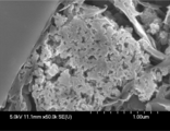
- FIG. 2 is an SEM image ( ⁇ 50.0K) of the lithium titanate particle group of Comparative Example 1.
- the lithium titanate particle group of Comparative Example 1 to which the silane coupling agent was not added has a three-dimensional network structure.
- the coat layer C is not formed on the outer peripheral surface of the lithium titanate particle group and the surface of the void.
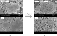
- FIG. 3 is an SEM image of the lithium titanate particle groups of Comparative Example 4 and Example 2.
- FIG. 3A is an SEM image of the lithium titanate particle group of Comparative Example 4, and the magnification is ⁇ 50.0K in the upper stage and ⁇ 100K in the lower stage.
- the silane coupling agent was mixed at 10 wt% and only dried, the outer peripheral surface of the lithium titanate particle group and the surfaces of the voids became the silane coupling agent. It looks like it is covered.
- the silane coupling agent adheres to the lithium titanate particle group so as to fill the voids of the lithium titanate particle group.
- FIG. 3 (b) is a SEM image of the lithium titanate particle group of Example 2, and the magnification is ⁇ 50.0K in the upper stage and ⁇ 100K in the lower stage.
- silane was formed on the outer peripheral surface of the lithium titanate particle group and the surface of the voids.
- a coat layer containing a silicon oxide derived from the coupling agent is formed. The coat layer is formed on the surface of the lithium titanate particles even in the voids of the lithium titanate particle group, but is not in a state of being formed so as to fill the voids.
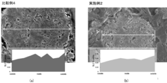
- FIG. 4A shows the analysis result of the lithium titanate particle group of Comparative Example 4
- FIG. 4B shows the analysis result of the lithium titanate particle group of Example 2.
- Elemental analysis was carried out so as to cross the diameter portion of the lithium titanate particle group as indicated by the arrow in the SEM image in each figure.
- the vertical axis plots the Si / Ti ratio to verify the proportion of Si derived from the silane coupling agent.
- a nitrogen gas adsorption measuring method is used as a measuring method. Specifically, nitrogen gas is introduced into the surfaces of the lithium titanate particles and the pores formed inside the lithium titanate particles, and the adsorption amount of the nitrogen gas is determined. Next, the pressure of the introduced nitrogen gas is gradually increased, the adsorption amount of nitrogen gas is plotted against each equilibrium pressure, and an adsorption isotherm curve is obtained. The measurement was performed using a high-precision gas / vapor adsorption amount measuring device BELSORP-max-N (manufactured by Bell Japan Ltd.).
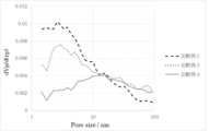
- FIG. 5 and 6 are graphs in which the horizontal axis represents the pore diameter and the vertical axis plots the pore volume change rate dV p / d (r p ).
- FIG. 5 shows pore size distribution data of Comparative Examples 2 to 4 which were not heated.
- Comparative Examples 3 and 4 in which the silane coupling agent was mixed, in comparison with Comparative Example 2 in which the silane coupling agent was not mixed, the voids of 10 nm or less were remarkably reduced. That is, it was found that in Comparative Examples 3 and 4 in which the silane coupling agent was mixed, the voids were filled with the silane coupling agent.
- FIG. 6 shows pore size distribution data of Comparative Example 1, Example 1 and Example 2 which were heated.
- Examples 1 and 2 in which the silane coupling agent was mixed have the same degree of voids as Comparative Example 1 in which the silane coupling agent is not mixed.
- the pore volume change rate of the pore diameter of 10 nm or less has a value exceeding 0.008 dV p / dr p .
- the rate of change in pore volume does not have to be uniformly over 0.008 for pore diameters of 10 nm or less, and may exceed 0.008 for some pores.
- the coating layer containing the silicon oxide derived from the silane coupling agent was formed, so that the clogging of the voids was eliminated. Do you get it.
- a lithium ion secondary battery was manufactured using the lithium titanate particles of Examples 1 to 4 and Comparative Examples 1 to 6. Specifically, 5% by weight of polyvinylidene fluoride and an appropriate amount of N-methylpyrrolidone are added to each particle group and sufficiently kneaded to form a slurry, which is applied onto an aluminum foil and dried to form a negative electrode.
- LMO particles, acetylene black as a conduction aid, and polyvinylidene fluoride (PVDF) as a binder were added to a solvent and stirred by a homogenizer to produce a slurry-like mixed solution.
- the sheet of the positive electrode active material layer obtained by applying this mixed solution to an aluminum current collector foil, drying and pressing was used as a positive electrode.
- An element was formed by interposing a cellulose separator between the positive electrode and the negative electrode, and the element was impregnated with an electrolytic solution.
- the electrolyte used was 1.6 molar LiBF 4 as a solute, and ⁇ -butyrolactone (GBL) was used as a solvent. Then, the element impregnated with the electrolytic solution was heat-sealed using a laminate film to manufacture lithium ion secondary batteries according to Examples 1 to 4 and Comparative Examples 1 to 6.
- FIG. 7 shows the results of measuring the initial internal resistance (DCIR) of the lithium ion secondary batteries of Examples 1 to 4 and Comparative Examples 1 to 6 thus created.
- the series connecting the plots with circles is the series that has undergone the heating process, and is the result of Comparative Example 1 and Examples 1 to 4, and the series connecting the plots with the triangles omits the heating process. It is a series of the above, and is composed of the results of Comparative Examples 2 to 6.
- Comparative Examples 3 to 6 in which the silane coupling agent is mixed are Comparative Examples in which the silane coupling agent is not mixed.
- the internal resistance was greatly increased compared to 2. Comparing the series of triangles and the series of circles, it was found that in each mixing ratio, the increase in internal resistance was suppressed in Examples 1 to 4 in which the heat treatment was performed. It is considered that in Comparative Examples 3 to 6 in which the heat treatment is not performed, the silane coupling agent fills the voids, so that the impregnation property of the electrolytic solution is lowered and the initial internal resistance is increased. Be done.
- FIG. 8 shows the rate of increase in internal resistance after 2000 cycles. The increase rate of the internal resistance was calculated from the internal resistance after charge / discharge / the initial internal resistance.
- the series connected with the circles is the series that has undergone the heating step, and is the result of Comparative Example 1 and Examples 1 to 4, and the series connected with the triangles has the heating step omitted. It is a series of the above, and is composed of the results of Comparative Examples 2 to 6.
- Comparative Examples 1 and 2 the rate of increase in internal resistance was 166.4%. In Comparative Examples 1 and 2, since the silane coupling agent was not mixed, deposits were formed on the negative electrode, and the internal resistance was significantly increased. Comparing the heat-treated Comparative Example 1 and Examples 1 to 4 with reference to the circled series, first, in Example 4 in which 3 wt% of the silane coupling agent was mixed, the increase rate was 118.4%. Yes, the rate of increase is suppressed as compared with Comparative Example 1. In addition, in Example 1 in which 5 wt% of the silane coupling agent was mixed, the increase rate was 93.3%, which is suppressed as compared with Comparative Example 1.
- Example 2 in which the silane coupling agent was mixed at 10 wt% was 61.2%, and the effect of suppressing the increase rate was enhanced.
- Example 3 in which 20 wt% of the silane coupling agent was mixed was 62.5%, which was slightly higher than that of Example 2. From this result, it was found that the effect of suppressing the increase rate was flat even when the silane coupling agent was mixed in an amount of 10 wt% or more.
- the silane coupling agent was mixed in excess of 20 wt%, the initial internal resistance was significantly increased. It was also found that when the silane coupling agent was mixed in an amount of 1 wt% or more, the formation of deposits was prevented and the increase in internal resistance after charge / discharge could be suppressed.
- the mixing amount of the silane coupling agent is set to 3 to 10% by weight, it is possible to suppress the increase in the initial internal resistance of the electricity storage device and to appropriately suppress the increase rate of the internal resistance after charging and discharging. It became clear that it was possible.
- Comparative Examples 2 to 6 in which the heat treatment is not performed are examined with reference to the series of triangular marks, Comparative Examples 3 to 6 in which the silane coupling agent is mixed are Comparative Examples in which the silane coupling agent is not mixed. Compared with No. 2, the increase rate of the internal resistance is decreased. Therefore, it was confirmed that the effect of suppressing the increase rate can be obtained by mixing the silane coupling agent.
- a lithium ion secondary battery was manufactured using the lithium titanate particles of Examples 5 to 8 prepared using an epoxy-based silane coupling agent as the negative electrode active material layer.
- the manufacturing method and manufacturing conditions of these lithium ion secondary batteries are the same as those of the lithium ion secondary batteries using the lithium titanate particles of Examples 1 to 4 and Comparative Examples 1 to 6.
- the initial stage of the lithium ion secondary battery using the lithium titanate particle group of Examples 5 to 8 The internal resistance (DCIR) and the increase rate of the internal resistance after 2000 cycles were measured.
- the method of measuring the initial internal resistance and the rate of increase of the internal resistance is the same as in Examples 1 to 4 and Comparative Example 1.
- FIG. 9 is a graph showing the relationship between the amount of silane coupling agent added and the initial internal resistance (DCIR).
- FIG. 10 is a graph showing the relationship between the amount of silane coupling agent added and the rate of increase in internal resistance. As shown in FIGS. 9 and 10, it was confirmed that the initial internal resistance (DCIR) and the increase rate of the internal resistance showed the same tendency as in Examples 1 to 4 even if the type of the silane coupling agent was changed. Was done.
- the silane coupling agent prevents deposit formation if it is mixed in an amount of 1 wt% or more. Then, it was confirmed that if the addition amount of the silane coupling agent was 20 wt% or less, the increase in the internal resistance due to the increase in the silane coupling agent was moderated regardless of the type of the silane coupling agent. Furthermore, by setting the mixing amount of the silane coupling agent to 3 to 10 wt%, the initial increase in the internal resistance of the electricity storage device is suppressed regardless of the type of the silane coupling agent, and the internal resistance after charge and discharge is increased. It has been clarified that the rate of increase can be suitably suppressed.
- a lithium ion secondary battery was manufactured using the lithium titanate particles of Examples 9 to 12 prepared while adding lithium hydroxide as a silane coupling agent and an alkaline compound as an active material layer of the negative electrode.
- the manufacturing method and manufacturing conditions of these lithium ion secondary batteries are the same as those of the lithium ion secondary batteries using the lithium titanate particles of Examples 1 to 8 and Comparative Examples 1 to 5.
- the initial stage of the lithium ion secondary battery using the lithium titanate particle group of Examples 9 to 12 was used.
- the internal resistance (DCIR) and the increase rate of the internal resistance after 2000 cycles were measured.
- the method of measuring the initial internal resistance and the increase rate of the internal resistance is the same as in Examples 1 to 8 and Comparative Example 1.
- FIG. 11 is a graph showing the relationship between the amount of silane coupling agent added and the initial internal resistance (DCIR).
- FIG. 12 is a graph showing the relationship between the amount of silane coupling agent added and the rate of increase in internal resistance.
- the initial internal resistance (DCIR) of the lithium titanate particles was higher than that in the case where the alkali compound was not added. It was confirmed that the value did not change or fell slightly.
- the increase rate of the internal resistance is higher than that in the case where the alkali compound is not added. It was confirmed that it was further suppressed.
- the addition amount of the silane coupling agent was 20 wt%, there was a difference of 6.9% in the increase rate of the internal resistance depending on whether or not the alkali compound was added.
- the increase rate of the internal resistance when the addition amount of the silane coupling agent is 20 wt% is the same as that when the addition amount of the silane coupling agent is not added and the addition amount of the silane coupling agent is 10 wt%.
- the addition amount of the silane coupling agent was 20 wt%.
- lithium hydroxide as an alkali compound
- a pretreatment such as filtration and drying was performed, and then lithium titanate of Example 13 produced using a silane coupling agent.
- the manufacturing method and manufacturing conditions of these lithium ion secondary batteries are the same as those of the lithium ion secondary batteries using the lithium titanate particles of Examples 1 to 8 and Comparative Examples 1 to 5.
- the initial internal resistance (DCIR) and the increase rate of the internal resistance after 2000 cycles were measured.
- the method of measuring the initial internal resistance and the increase rate of the internal resistance is the same as in Examples 1 to 8 and Comparative Example 1.
- Example 13 the results of the lithium ion secondary battery in which the lithium titanate particles of Example 9 are used as the active material layer of the negative electrode are also shown.
- Example 13 the lithium titanate particle group was pretreated with an alkali compound and then moved to the mixing step of the silane coupling agent, whereas in Example 9, the lithium titanate particle group, the alkali compound and the silane coupling agent were mixed.
- Example 9 and Example 13 differ in that the agent was mixed.
- Example 13 As shown in Table 1, almost no difference was found between Examples 9 and 13 in the initial internal resistance. However, in Example 13, the rate of increase in internal resistance after 2000 cycles was even better. That is, it was confirmed that the pretreatment of the metal compound particle group with the alkali compound further enhances the effect of suppressing the increase rate of the internal resistance.
- a mixed solvent was prepared by adding lithium titanate particles and a silane coupling agent (10 wt%) to isopropyl alcohol.
- the mixed solvent was stirred using a homogenizer, and the obtained aggregate was dried at 150 ° C. for 12 hours. No heat treatment was performed.
- the dried powder was washed 3 times with isopropyl alcohol. The washed powder was dried at 150 ° C. for 12 hours.
- Fig. 13 (a) shows the result of thermogravimetric measurement of the dried powder and the washed and dried powder. From FIG. 13A, in the powder before cleaning, the weight of 5.24 wt% is lost due to heating. On the other hand, in the powder dried after washing, the weight lost by heating was 1.51 wt%. When the loss amount of 1.51 wt% was converted into the amount of the silane coupling agent, it was 1.7 wt% as shown in FIG. 13 (b). That is, it was clarified that the silane coupling agent contained 10 wt% before the cleaning was reduced to 1.7 wt% after the cleaning. As described above, in Comparative Examples 3 to 6 in which the heat treatment was not performed, the silane coupling agent was dissolved in the solvent, so that it was found that the effect of suppressing the increase in internal resistance was low as described above.
- the amount of the silane coupling agent is 1.7 wt% with respect to the total amount of lithium titanate particles, the content of Si element contained in the lithium titanate particles will be 0.3 wt% by conversion. Therefore, from the results shown in FIG. 13, by adding 10 wt% of a silane coupling agent, a lithium titanate particle group containing Si element at a ratio of 0.3 wt% was produced when heat treatment was not performed. It can be said that it was done.
- the amount of Si element remaining in the lithium titanate particle groups of Examples 1 to 4 and Comparative Example 1 was measured.
- the alkali melting method was used as the method for quantifying the Si element. That is, the lithium titanate particles of Examples 1 to 4 and Comparative Example 1 and a flux were placed in a platinum crucible and melted by heating, and an acid was further added to the titanium of Examples 1 to 4 and Comparative Example 1. The lithium acid particle group was dissolved. Then, the amount of Si was quantified by ICP-AES (high frequency inductively coupled plasma optical emission spectroscopy). The result is shown in FIG.
- FIG. 14 is a graph showing the relationship between the amount of silane coupling agent added and the amount of Si element contained in the lithium titanate particle group.
- the silane coupling agent is added at 3 wt% or more and 20 wt% and heat treatment is performed after the mixing step as in Examples 1 to 4.
- a lithium titanate particle group having a Si element content of 0.4 wt% or more and 3.0 wt% or less can be produced, and it has been confirmed that this lithium titanate particle group can effectively suppress an increase in internal resistance.
- a silane coupling agent is added at 3 wt% or more and 10 wt% and heat treatment is performed after the mixing step as in Examples 1, 2, and 4.
- a lithium titanate particle group having a Si element content of 0.4 wt% or more and 1.4 wt% or less can be produced, and the initial internal resistance can also be suppressed by the lithium titanate particle group. ..
- FIG. 15A is a graph showing the carbon concentration (wt%) of the silane coupling agent at each heating temperature.
- FIG. 15B is a graph showing the silicon concentration (wt%) of the silane coupling agent at each heating temperature.
- FIG. 15C is a graph showing the carbon / silicon ratio at each heating temperature.
- the carbon content of the silane coupling agent decreased as the heating temperature increased.
- the heating temperature was 300 ° C.
- the carbon content was remarkably reduced and almost disappeared at 400 ° C.
- the silicon content of the silane coupling agent showed a substantially constant value regardless of the heating temperature.
- the heating step causes the carbon of the silane coupling agent to disappear, resulting in a structure very close to that of silicon oxide. It was speculated that That is, it was considered that when the silane coupling agent was heated at 300 to 600 ° C., it became a silicon oxide, not a silane coupling agent, and a coat layer was formed on the surface of the metal compound particle group.
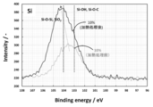
- FIG. 16 is a graph showing the results of measuring the lithium titanate particle group before the heat treatment and the lithium titanate particle group after the heat treatment.
- the binding energy of 103 eV indicates that Si—OH and Si—O—C are constituent functional groups.
- the binding energy of 104 eV indicates that Si—O—Si and SiO 2 are constituent functional groups.
- the spectrum of the lithium titanate particle group before heat treatment has a peak at an intermediate point between 103 eV and 104 eV.
- the peak shifts around 104 eV. That is, although it is considered that the lithium titanate particle group after the heat treatment also contains SiO and Si, it was found that the particles had a peak very close to that of SiO 2 .
- FIG. 17 shows the result of X-ray diffraction analysis performed on the lithium titanate particles after the heat treatment.
- SiO 2 has a peak near 24 degrees.
- the peak indicating SiO 2 did not appear. This is because the peak of SiO 2 detected at around 24 degrees by X-ray diffraction analysis is due to crystalline silicon oxide. That is, although a peak very close to SiO 2 was confirmed by X-ray photoelectron spectroscopy analysis, a peak indicating SiO 2 was not confirmed by X-ray diffraction analysis, so that the silicon oxide contained in the coat layer was amorphous. It turned out.
- FIG. 18 (a) shows solid-state 1 H-NMR data measured for the obtained lithium titanate particle groups of Example 2 and Comparative Example 1. The measurement was performed using a nuclear magnetic resonance analyzer (JNM-ECA600 manufactured by JEOL Ltd.). The peak existing at 5 to 8 ppm indicates the surface hydroxyl group (Bridge OH) of the lithium titanate particle group.
- Fig. 13 (b) shows the result of calculating the integrated intensity of the peak existing at 5 to 8 ppm in Fig. 18 (a) using the waveform separation software.
- FIG. 18B it is found that the integrated strength of the lithium titanate particle group of Example 2 is reduced by about 44% as compared with the integrated strength of the lithium titanate particle group of Comparative Example 1. It was That is, it is shown that the peak of the hydroxyl group (Bridge OH) existing on the surface of the lithium titanate particle group of Example 2 is reduced by the adhesion of the silicon compound. In other words, in Example 2, it is considered that about 44% of the surface of the lithium titanate particle group of Comparative Example 1 not coated with silicon oxide is coated with silicon oxide.
- FIG. 19 shows an increase rate of the internal resistance value after 2000 cycles of the lithium ion secondary batteries using the lithium titanate particle groups of Example 1, Example 2 and Comparative Example 1.
- Example 1 in which the reduction rate of integrated intensity is 29%
- Example 2 in which the reduction rate of integrated intensity is 44%
- the internal resistance after 2000 cycles is higher than that of the lithium ion secondary battery of Comparative Example 1.
- the rate of increase in value was suppressed, and good results were obtained. This is considered to be because the coating of the surface of the lithium titanate particles with the silicon oxide resulted in the suppression of deposit formation on the negative electrode.
- a reduction rate of the integrated strength of the lithium titanate particles of 25% or more is desirable from the viewpoint of suppressing the increase in internal resistance.
Landscapes
- Chemical & Material Sciences (AREA)
- Engineering & Computer Science (AREA)
- Electrochemistry (AREA)
- Chemical Kinetics & Catalysis (AREA)
- General Chemical & Material Sciences (AREA)
- Power Engineering (AREA)
- Materials Engineering (AREA)
- Composite Materials (AREA)
- Manufacturing & Machinery (AREA)
- Microelectronics & Electronic Packaging (AREA)
- Inorganic Chemistry (AREA)
- Battery Electrode And Active Subsutance (AREA)
- Electric Double-Layer Capacitors Or The Like (AREA)
- Inorganic Compounds Of Heavy Metals (AREA)
- Secondary Cells (AREA)
Abstract
蓄電デバイスの内部抵抗の増加を抑制することができる金属化合物粒子群、金属化合物粒子群を含む蓄電デバイス用電極、および金属化合物粒子群の製造方法を提供する。金属化合物粒子が連なった三次元網目構造を有する金属化合物粒子群であって、この金属化合物粒子群の一部に、珪素酸化物を含むコート層Cが形成されている。珪素酸化物を含むコート層Cは、金属化合物粒子の表面の少なくとも一部に形成されている。三次元網目構造には、空隙2が存在し、空隙2を画成する金属化合物粒子には、その表面に珪素酸化物を含むコート層Cが形成されている。コート層Cに含まれる珪素酸化物が、アモルファス状の珪素酸化物である。
Description
本発明は、金属化合物粒子群、蓄電デバイス用電極、蓄電デバイス、および金属化合物粒子群の製造方法に関する。
近年、デジタルカメラやスマートフォンや携帯型PCの急速な普及により二次電池の開発が活発になっている。二次電池は、燃料の高騰や環境負荷に対する意識の高まりを受けた自動車の動力用又はスマートグリッドの蓄電用への応用も期待されている。
二次電池の電極は、リチウムイオンを可逆的に吸蔵及び放出する活物質を含有する正極及び負極と、リチウム塩を溶解させた電解液とを有する。このリチウム二次電池では、充放電によりリチウムイオンが正極から放出されて負極へと吸蔵され、放電によりリチウムイオンが負極から放出されて正極へ吸蔵される。リチウムイオン二次電池は、高電圧で作動可能でありエネルギー密度が大きいという利点を有する。
また、リチウムイオン二次電池と電気二重層キャパシタの双方の長所を活かすべく所謂ハイブリッドキャパシタが提案されている。ハイブリッドキャパシタは、電気二重層容量を有する分極性電極を正極とし、リチウムの吸蔵及び放出が可能な金属化合物粒子を負極とし、リチウムイオン二次電池と電気二重層キャパシタのメリットを兼ね備える。すなわち、このハイブリッドキャパシタは、高エネルギー密度を有し、高い入出力特性を有する。
これらの蓄電デバイスの電極材料として用いられる金属化合物粒子を負極材料として用いた場合、充放電を行うことで負極に堆積物が生じることがあった。この堆積物は、SEIと呼ばれる皮膜とは異なり、堆積物が生じた時点で内部抵抗の増加を招いていた。
そこで、本発明の目的は、蓄電デバイスの内部抵抗の増加を抑制することができる金属化合物粒子群、金属化合物粒子群を含む蓄電デバイス用電極、および金属化合物粒子群の製造方法を提供することである。
上記の課題を達成するために、本実施形態に係る金属化合物粒子群は、次の構成を有する。
(1)金属化合物粒子が連なった三次元網目構造を有する金属化合物粒子群であって、この金属化合物粒子群の一部に、珪素酸化物を含むコート層が形成されている。
(1)金属化合物粒子が連なった三次元網目構造を有する金属化合物粒子群であって、この金属化合物粒子群の一部に、珪素酸化物を含むコート層が形成されている。
(2)前記珪素酸化物を含むコート層は、前記金属化合物粒子の表面の少なくとも一部に形成されていても良い。
(3)Si元素の量は、金属化合物粒子群全体に対して0.4以上3.0wt%以下であるようにしても良い。
(4)前記三次元網目構造には、空隙が存在し、前記空隙を画成する前記金属化合物粒子には、前記珪素酸化物を含むコート層が形成されていても良い。
(5)前記コート層に含まれる珪素酸化物が、アモルファス状の珪素酸化物であっても良い。
(6)前記金属化合物粒子群を窒素ガス吸着測定法にて測定した細孔分布から換算される細孔容積変化率であって、10nm以下の細孔径に対して0.008dVp/drp超の細孔容積変化率を有していても良い。
(7)前記珪素酸化物を含むコート層が形成されていない金属化合物粒子群に対して、積分強度の減少率が25%以上であっても良い。
(8)前記金属化合物粒子がチタン酸リチウムであっても良い。
上記の金属化合物粒子群を含む蓄電デバイス用電極とすることもできる。また、蓄電デバイス用電極である負極と、正極と、を有する素子と、前記素子に含浸される電解液と、を有し、前記電解液がフッ素含有化合物を含む蓄電デバイスとすることもできる。
また、本実施形態の金属化合物粒子群の製造方法は、ベースとなる金属化合物粒子群と、珪素酸化物の原料を混合する混合工程と、混合工程により得られた粉末を300~600℃で加熱する加熱工程とを含む。
前記珪素酸化物の原料は、ベースとなる金属化合物粒子群の重量に対して、1~20wt%の割合で混合されていても良い。
前記珪素酸化物の原料は、ベースとなる金属化合物粒子群の重量に対して、3~20wt%の割合で混合されていても良い。
前記混合工程では、アルカリ化合物を1種又は2種以上更に混合されていても良い。または、前記混合工程の前に、ベースとなる金属化合物粒子群をアルカリ化合物で前処理する前処理工程を含むようにしてもよい。前記アルカリ化合物としては、アルカリ金属又はアルカリ土類金属の水酸化物、酢酸塩、硫酸塩、炭酸塩、硝酸塩、塩化物、無機系アルカリ剤又は有機系アルカリ剤が挙げられる。
本発明によれば、蓄電デバイスの内部抵抗の増加を抑制することができる金属化合物粒子群、金属化合物粒子群を含む蓄電デバイス用電極、および金属化合物粒子群の製造方法を提供することができる。
以下、本発明を実施する形態について、説明する。なお、本発明は、以下に説明する実施形態に限定されるものでない。
[1.構成]
金属化合物粒子群は、主に蓄電デバイスの電極に用いられるものである。金属化合物粒子群を構成する金属化合物粒子としては、リチウムイオン二次電池やリチウムイオンキャパシタなどの蓄電デバイスの正極活物質又は負極活物質として動作可能な材料である。金属化合物粒子群は、ナノサイズの金属化合物粒子が連なった三次元網目構造を有し、金属化合物粒子群の一部に、珪素酸化物(SiOxもしくはSiOx(OH)4-2X(xは、0~2)を含むコート層が形成されている。この珪素酸化物を含むコート層は、金属化合物粒子の表面の少なくとも一部に形成されている。また、金属化合物粒子群の三次元網目構造には、空隙が存在し、空隙を画成する金属化合物粒子には、その表面に珪素酸化物を含むコート層が形成されている。
金属化合物粒子群は、主に蓄電デバイスの電極に用いられるものである。金属化合物粒子群を構成する金属化合物粒子としては、リチウムイオン二次電池やリチウムイオンキャパシタなどの蓄電デバイスの正極活物質又は負極活物質として動作可能な材料である。金属化合物粒子群は、ナノサイズの金属化合物粒子が連なった三次元網目構造を有し、金属化合物粒子群の一部に、珪素酸化物(SiOxもしくはSiOx(OH)4-2X(xは、0~2)を含むコート層が形成されている。この珪素酸化物を含むコート層は、金属化合物粒子の表面の少なくとも一部に形成されている。また、金属化合物粒子群の三次元網目構造には、空隙が存在し、空隙を画成する金属化合物粒子には、その表面に珪素酸化物を含むコート層が形成されている。
(金属化合物粒子群)
図1に示す通り、金属化合物粒子群Aは三次元網目構造を有する。三次元網目構造は、ナノサイズである金属化合物の一次粒子1が結合して網目状に連なり、ナノサイズの空隙2が存在する構造を示す。一次粒子1の結合界面には粒界が無く、一方で一次粒子1間に微小の細孔が多数存在する。この金属化合物粒子群Aにおいて、三次元網目構造は、負極活物質の電子パスを形成し、空隙2は電解液の貯蔵地となり、一次粒子1間の細孔はイオンのパスになると考えられる。
図1に示す通り、金属化合物粒子群Aは三次元網目構造を有する。三次元網目構造は、ナノサイズである金属化合物の一次粒子1が結合して網目状に連なり、ナノサイズの空隙2が存在する構造を示す。一次粒子1の結合界面には粒界が無く、一方で一次粒子1間に微小の細孔が多数存在する。この金属化合物粒子群Aにおいて、三次元網目構造は、負極活物質の電子パスを形成し、空隙2は電解液の貯蔵地となり、一次粒子1間の細孔はイオンのパスになると考えられる。
金属化合物粒子は、リチウムイオンを吸蔵及び放出することが可能な粒子である。金属化合物粒子としては、FeO、Fe2O3、Fe3O4、MnO、MnO2、Mn2O3、Mn3O4、CoO、Co3O4、NiO、Ni2O3、TiO、TiO2、TiO2(B)、TiNb2O7、Nb2O5、CuO、NiO、SnO、SnO2、SiO2、RuO2、WO、WO2、WO3、MoO3、ZnO等の酸化物、Sn、Si、Al、Zn等の金属、LiVO2、Li3VO4、Li4Ti5O12、Sc2TiO5、Fe2TiO5、Li2Na2Ti6O14、Li2BaTi6O14、Li2SrTi6O14などの複合酸化物、Li2.6Co0.4N、Ge3N4、Zn3N2、Cu3Nなどの窒化物、Y2Ti2O5S2、MoS2が挙げられる。
これらの金属化合物粒子のうち、特に、リチウムを含む酸化物又は酸素酸塩について具体的に説明する。リチウムを含む酸化物又は酸素酸塩は、LiαMβYγで表される。金属酸化物の場合、例えば、M=Co,Ni,Mn,Ti,Si,Sn,Al,Zn,Mg、Nb、Vの何れかであり、Y=Oである。金属酸素酸塩の場合、例えば、M=Fe,Mn,V,Co,Niの何れかであり、Y=PO4,SiO4,BO3,P2O7の何れかである。Mβは、MδM’εの合金であってもよく、例えば、M=Sn,Sb,Siの何れかであり、M’=Fe,Co,Mn,V,Ti,Niの何れかである。例えば、リン酸鉄リチウム、チタン酸リチウム、コバルト酸リチウム、リン酸バナジウムリチウム、リン酸鉄マンガンリチウムが使用できる。なかでも、チタン酸リチウム(Li4Ti5O12)が好ましい。
三次元網目構造の断面における空隙率は好ましくは7~50%の範囲である。空隙率が7%未満では、電解液と接する面積が少なく、電解液中のイオンの移動に影響を与える。また空隙率が50%を超えると、一次粒子1同士の結合が粗くなり三次元網目構造を形成しづらくなる。
一次粒子1の平均粒子径は5~300nmの範囲である。平均粒子径の算出方法は次の通りとする。まず、走査電子顕微鏡を用いて一次粒子1を観察し、少なくとも一次粒子1が150個以上含まれる画像を撮影する。撮影した一枚の視野(画像)に含まれる一次粒子1の楕円形の像の長径と短径を測定し、この長径と短径の平均値を各一次粒子1について算出する。そして、各一次粒子1の平均値を加算するとともに、測定した一次粒子1の個数でその加算値を除算する。この結果が5~300nmの範囲に収まる。
5~300の範囲の一次粒子1が結合して三次元網目構造を形成すると、金属化合物粒子はナノサイズの細孔を多く獲得する。これにより、電解液と接する金属化合物粒子の面積が増加し、電解液中のイオンの移動が円滑となる。また、この金属化合物粒子の細孔を測定したところ、微細な細孔が多く存在する。特に、40nm以下の微細な細孔も多く含む。
三次元網目構造を有する金属化合物粒子について、窒素ガス吸着測定法にて測定した細孔分布から差分細孔容積を換算した。その結果、10~40nmの範囲の細孔径における差分細孔容積が0.01cm3/g以上の値を有し、特に0.02cm3/g以上の値が多く得られる。従って、電解液との接する面積が増え、電解液との接する面積が多いほど、負極に用いられた際の放電レート特性が向上する。
(コート層)
コート層Cは、金属化合物粒子群Aの一部に形成されている。特に、金属化合物粒子の表面の少なくとも一部に形成されていると良い。コート層Cは、珪素酸化物を含む層である。コート層Cは、金属化合物粒子群Aの空隙2を画成する金属化合物粒子の表面に形成されていても良い。すなわち、コート層Cは、金属化合物粒子群Aの外周面側に加えて、金属化合物粒子群Aの内部構造における空隙2においても、金属化合物粒子の表面に形成されて良い。ただし、コート層Cは、空隙2を埋め尽くすほど形成されてはおらず、コート層Cが形成された金属化合物粒子群Aにおいても空隙2は残存する。このような金属化合物粒子群Aは、10nmの以下の細孔径に対して0.008dVp/drp超の細孔容積変化率を有する。また、珪素酸化物を含むコート層Cが形成されている金属化合物粒子群Aは、珪素酸化物を含むコート層Cが形成されていない金属化合物粒子群に対して、積分強度の減少率が25%以上である。
コート層Cは、金属化合物粒子群Aの一部に形成されている。特に、金属化合物粒子の表面の少なくとも一部に形成されていると良い。コート層Cは、珪素酸化物を含む層である。コート層Cは、金属化合物粒子群Aの空隙2を画成する金属化合物粒子の表面に形成されていても良い。すなわち、コート層Cは、金属化合物粒子群Aの外周面側に加えて、金属化合物粒子群Aの内部構造における空隙2においても、金属化合物粒子の表面に形成されて良い。ただし、コート層Cは、空隙2を埋め尽くすほど形成されてはおらず、コート層Cが形成された金属化合物粒子群Aにおいても空隙2は残存する。このような金属化合物粒子群Aは、10nmの以下の細孔径に対して0.008dVp/drp超の細孔容積変化率を有する。また、珪素酸化物を含むコート層Cが形成されている金属化合物粒子群Aは、珪素酸化物を含むコート層Cが形成されていない金属化合物粒子群に対して、積分強度の減少率が25%以上である。
このようなコート層Cは、金属化合物粒子群A中にSi元素の含有量が0.4以上3.0wt%以下となるように形成されていることが好ましく、この範囲であると、充放電後の内部抵抗の増加率を好適に抑制することができる。3.0wt%超になると、コート層は堆積物の発生抑制に対して過剰であり、これ以上の内部抵抗の増加率の抑制効果は期待できず、一方でコート層の影響が大きくなって初期の内部抵抗が増加する。更に好ましくは、コート層Cは、金属化合物粒子群A中にSi元素の含有量が0.4以上1.4wt%以下となるように形成されていることが好ましく、この範囲であると、コート層Cがバランス良く金属化合物粒子群Aに形成され、初期の内部抵抗値も抑制される。
コート層Cに含まれる珪素酸化物は、低い結晶性を有する。すなわち、珪素酸化物はアモルファスであり、完全な結晶構造を有さない。このようなアモルファス状の珪素酸化物は、金属化合物粒子との結合性が良いと考えられる。そのため、アモルファス状の珪素酸化物を含むコート層Cは、金属化合物粒子の表面において局所的に形成されない。すなわち、金属化合物粒子の表面において、均一に、かつ、金属化合物粒子にまとわりつくように形成されている。珪素酸化物と金属化合物粒子の結合状態は解析されていないが、おそらく金属化合物粒子の表面官能基と珪素酸化物が水素吸着等の物理吸着による結合、もしくは金属化合物粒子の表面官能基と珪素酸化物の表面官能基との化学結合であると考えられる。
なお、コート層Cには、珪素酸化物以外にも炭素が1%以下程度含まれている。従って、コート層Cには、炭素化合物もしくはSiOCnH2n+1やSiCといった成分が含まれていると推測される。
以上のような金属化合物粒子群Aは、ハイブリッドキャパシタやリチウムイオン二次電池等の蓄電デバイス用の電極材料として用いられる。本実施形態の金属化合物粒子群Aを用いたハイブリッドキャパシタの構成を一例として以下に説明する。
(1-1.蓄電デバイス)
リチウムイオン二次電池は蓄電デバイスの一例である。リチウムイオン二次電池では、正極と負極とをセパレータを介して対向させて素子を形成し、素子に電解液を含浸させてなる。リチウムイオン二次電池は、正負極のリチウムイオンの吸蔵及び放出の方向に応じて充放電する。正極及び負極は、それぞれ活物質の層を集電体に一体化させて成る。正極活物質及び集電体、並びに負極活物質及び集電体は、各々圧着又はドクターブレード法等を用いてバインダーを介して接合される。
リチウムイオン二次電池は蓄電デバイスの一例である。リチウムイオン二次電池では、正極と負極とをセパレータを介して対向させて素子を形成し、素子に電解液を含浸させてなる。リチウムイオン二次電池は、正負極のリチウムイオンの吸蔵及び放出の方向に応じて充放電する。正極及び負極は、それぞれ活物質の層を集電体に一体化させて成る。正極活物質及び集電体、並びに負極活物質及び集電体は、各々圧着又はドクターブレード法等を用いてバインダーを介して接合される。
集電体は、典型的には、アルミニウム、銅、鉄、ニッケル、チタン、鋼、カーボン等の導電材料である。特に、高い熱伝導性と電子伝導性とを有しているアルミニウム又は銅が好ましい。集電体の形状は、膜状、箔状、板状、網状、エキスパンドメタル状、円筒状等の任意の形状を採用することができる。
バインダーとしては、例えばフッ素系ゴム、ジエン系ゴム、スチレン系ゴム等のゴム類、ポリテトラフルオロエチレン、ポリフッ化ビニリデン等の含フッ素ポリマー、カルボキシメチルセルロース、ニトロセルロース等のセルロース、その他、ポリオレフィン樹脂、ポリイミド樹脂、アクリル樹脂、ニトリル樹脂、ポリエステル樹脂、フェノール樹脂、ポリ酢酸ビニル樹脂、ポリビニルアルコール樹脂、エポキシ樹脂などを挙げることができる。これらのバインダーは、単独で使用しても良く、2種以上を混合して使用しても良い。
(1-2.正極)
正極活物質層は、LMO粒子と導電助剤であるカーボンとバインダーを混練して成型され、集電体と合わせられる。カーボンとしては、導電性を有するものであれば特に限定なく使用でき、例えば、ケッチェンブラック、アセチレンブラック、チャネルブラック等のカーボンブラック、フラーレン、カーボンナノチューブ、カーボンナノファイバ、無定形炭素、炭素繊維、天然黒鉛、人造黒鉛、黒鉛化ケッチェンブラック、メソポーラス炭素、気相法炭素繊維等を挙げることができる。バインダーとしては、ポリテトラフルオロエチレン、ポリフッ化ビニリデン(PVDF)、テトラフルオロエチレン-ヘキサフルオロプロピレンコポリマー、ポリフッ化ビニル、カルボキシメチルセルロースなどの公知のバインダーが使用される。バインダーの含有量は、電極材料の総量に対して1以上30質量%以下であるのが好ましい。
正極活物質層は、LMO粒子と導電助剤であるカーボンとバインダーを混練して成型され、集電体と合わせられる。カーボンとしては、導電性を有するものであれば特に限定なく使用でき、例えば、ケッチェンブラック、アセチレンブラック、チャネルブラック等のカーボンブラック、フラーレン、カーボンナノチューブ、カーボンナノファイバ、無定形炭素、炭素繊維、天然黒鉛、人造黒鉛、黒鉛化ケッチェンブラック、メソポーラス炭素、気相法炭素繊維等を挙げることができる。バインダーとしては、ポリテトラフルオロエチレン、ポリフッ化ビニリデン(PVDF)、テトラフルオロエチレン-ヘキサフルオロプロピレンコポリマー、ポリフッ化ビニル、カルボキシメチルセルロースなどの公知のバインダーが使用される。バインダーの含有量は、電極材料の総量に対して1以上30質量%以下であるのが好ましい。
この正極活物質層には、他の正極活物質を加えてもよい。他の正極活物質としては、層状岩塩型LiMO2、層状Li2MnO3-LiMO2固溶体、及びスピネル型LiM2O4(式中のMは、Fe、Co、Ni、これらの組み合わせ、又はこれらとMnの組み合わせを意味する)が挙げられる。これらの具体例としては、LiCoO2、LiNiO2、LiNi4/5Co1/5O2、LiNi1/3Co1/3Mn1/3O2、LiNi1/2Mn1/2O2、LiFeO2、LiMnO2、Li2MnO3-LiCoO2、Li2MnO3-LiNiO2、Li2MnO3-LiNi1/3Co1/3Mn1/3O2、Li2MnO3-LiNi1/2Mn1/2O2、Li2MnO3-LiNi1/2Mn1/2O2-LiNi1/3Co1/3Mn1/3O2、LiMn3/2Ni1/2O4が挙げられる。
上記以外の他の正極活物質としては、イオウ及びLi2S、TiS2、MoS2、FeS2、VS2、Cr1/2V1/2S2などの硫化物、NbSe3、VSe2、NbSe3などのセレン化物、Cr2O5、Cr3O8、VO2、V3O8、V2O5、V6O13などの酸化物の他、LiNi0.8Co0.15Al0.05O2、LiVOPO4、LiV3O5、LiV3O8、MoV2O8、Li2FeSiO4、Li2MnSiO4、LiFePO4、LiFe1/2Mn1/2PO4、LiMnPO4、Li3V2(PO4)3などの複合酸化物が挙げられる。
(1-3.負極)
負極活物質は、上記の金属化合物粒子群Aであり、リチウムイオンを吸蔵及び放出することが可能な金属化合物粒子群である。例えば、チタン酸リチウムは、リチウムイオンの挿入・脱離によるエネルギー貯蔵機能を有する。その挿入・脱離の体積変化が約1%であるため、容量劣化が少ない。充放電電位が約1.55V(vs. Li/Li+)であるため、電解液の分解や急速充放電によるリチウム金属の析出などの副反応が生じにくく、サイクル特性に優れる。
負極活物質は、上記の金属化合物粒子群Aであり、リチウムイオンを吸蔵及び放出することが可能な金属化合物粒子群である。例えば、チタン酸リチウムは、リチウムイオンの挿入・脱離によるエネルギー貯蔵機能を有する。その挿入・脱離の体積変化が約1%であるため、容量劣化が少ない。充放電電位が約1.55V(vs. Li/Li+)であるため、電解液の分解や急速充放電によるリチウム金属の析出などの副反応が生じにくく、サイクル特性に優れる。
(1-4.セパレータ)
基材となるセパレータとしては、クラフト、マニラ麻、エスパルト、ヘンプ、レーヨン等のセルロースおよびこれらの混合紙、ポリエチレンテレフタレート、ポリブチレンテレフタレート、ポリエチレンナフタレート、それらの誘導体などのポリエステル系樹脂、ポリテトラフルオロエチレン系樹脂、ポリフッ化ビニリデン系樹脂、ビニロン系樹脂、脂肪族ポリアミド、半芳香族ポリアミド、全芳香族ポリアミド等のポリアミド系樹脂、ポリイミド系樹脂、ポリエチレン樹脂、ポリプロピレン樹脂、トリメチルペンテン樹脂、ポリフェニレンサルファイド樹脂、アクリル樹脂等の樹脂を単独で又は混合して用いることができる。
基材となるセパレータとしては、クラフト、マニラ麻、エスパルト、ヘンプ、レーヨン等のセルロースおよびこれらの混合紙、ポリエチレンテレフタレート、ポリブチレンテレフタレート、ポリエチレンナフタレート、それらの誘導体などのポリエステル系樹脂、ポリテトラフルオロエチレン系樹脂、ポリフッ化ビニリデン系樹脂、ビニロン系樹脂、脂肪族ポリアミド、半芳香族ポリアミド、全芳香族ポリアミド等のポリアミド系樹脂、ポリイミド系樹脂、ポリエチレン樹脂、ポリプロピレン樹脂、トリメチルペンテン樹脂、ポリフェニレンサルファイド樹脂、アクリル樹脂等の樹脂を単独で又は混合して用いることができる。
(1-5.電解液)
電解液の電解質はリチウムイオン源となるリチウム塩である。リチウム塩としては、LiPF6、LiBF4、LiClO4、LiN(SO2CF3)2、LiN(SO2C2F5)2、CF3SO3Li、LiC(SO2CF3)3、およびLiPF3(C2F5)3、またはこれらの混合物である。リチウム塩の濃度は、一般には0.1~2.5mol/L、好ましくは0.5~2mol/Lの範囲である。
電解液の電解質はリチウムイオン源となるリチウム塩である。リチウム塩としては、LiPF6、LiBF4、LiClO4、LiN(SO2CF3)2、LiN(SO2C2F5)2、CF3SO3Li、LiC(SO2CF3)3、およびLiPF3(C2F5)3、またはこれらの混合物である。リチウム塩の濃度は、一般には0.1~2.5mol/L、好ましくは0.5~2mol/Lの範囲である。
電解質として、リチウム塩に加えて四級アンモニウム塩を添加してもよい。四級アンモニウム塩は、リチウム塩が1.6M以上のモル濃度であるのに対し、特に限定はないが例えば1Mのモル濃度で添加される。四級アンモニウム塩としては、カチオンとしてテトラエチルアンモニウム、トリエチルメチルアンモニウム、ジエチルジメチルアンモニウム、エチルトリメチルアンモニウム、メチルエチルピロリジニウム、スピロビピロリジニウム、スピロ-(N,N’)-ビピロリジニウム、1-エチル-3-メチルイミダゾリウム、1-エチル-2,3-ジメチルイミダゾリウム等を挙げることができ、アニオンとしては、BF4
-、PF6
-、ClO4
-、AsF6
-、SbF6
-、AlCl4
-、またはRfSO3
-、(RfSO2)2N-、RfCO2
-(Rfは炭素数1~8のフルオロアルキル基)等を挙げることができる。
電解液の溶媒としては、以下に挙げるものが用いられる。なお、これらの溶媒はそれぞれ単独で使用してもよく、2種以上混合して使用してもよい。例えば、環状炭酸エステル、鎖状炭酸エステル、リン酸エステル、環状エーテル、鎖状エーテル、ラクトン化合物、鎖状エステル、ニトリル化合物、アミド化合物、スルホン化合物等を挙げることができる。環状炭酸エステルとしては、エチレンカーボネート、プロピレンカーボネート、ブチレンカーボネート、4-フルオロ-1,3-ジオキソラン-2-オン、4-(トリフルオロメチル)-1,3-ジオキソラン-2-オンなどが挙げられ、好ましくは、エチレンカーボネート、プロピレンカーボネートである。
鎖状炭酸エステルとしては、ジメチルカーボネート、エチルメチルカーボネート、ジエチルカーボネート、メチルn-プロピルカーボネート、メチルイソプロピルカーボネート、n-ブチルメチルカーボネート、ジエチルカーボネート、エチルn-プロピルカーボネート、エチルイソプロピルカーボネート、n-ブチルエチルカーボネート、ジn-プロピルカーボネート、ジイソプロピルカーボネート、ジn-ブチルカーボネート、フルオロエチルメチルカーボネート、ジフルオロエチルメチルカーボネート、トリフルオロエチルメチルカーボネートなどが挙げられ、好ましくは、ジメチルカーボネート、エチルメチルカーボネート、ジエチルカーボネートである。
リン酸エステルとしては、リン酸トリメチル、リン酸トリエチル、リン酸エチルジメチル、リン酸ジエチルメチルなどが挙げられる。環状エーテルとしては、テトラヒドロフラン、2-メチルテトラヒドロフランなどが挙げられる。鎖状エーテルとしては、ジメトキシエタンなどが挙げられる。ラクトン化合物としては、γ-バレロラクトン、γ-ブチロラクトンなどが挙げられる。鎖状エステルとしては、メチルプロピオネート、メチルアセテート、エチルアセテート、メチルホルメートなどが挙げられる。ニトリル化合物としては、アセトニトリルなどが挙げられる。アミド化合物としては、ジメチルホルムアミドなどが挙げられる。スルホン化合物としては、スルホラン、メチルスルホラン、ジメチルスルホン、エチルメチルスルホン、イソプロピルスルホンなどが挙げられるが、これらに限定されるものではない。
[2.製造方法]
本発明にかかる金属化合物粒子群の製造方法は、次の工程を有するものである。
(1)ベースとなる金属化合物粒子群と、珪素酸化物の原料を混合する混合工程
(2)混合工程により得られた粉末を300~600℃で加熱する加熱工程
本発明にかかる金属化合物粒子群の製造方法は、次の工程を有するものである。
(1)ベースとなる金属化合物粒子群と、珪素酸化物の原料を混合する混合工程
(2)混合工程により得られた粉末を300~600℃で加熱する加熱工程
なお、本実施形態の金属化合物粒子群Aは、ベースとなる金属化合物粒子群を基に作成される。ベースとなる金属化合物粒子群は、三次元網目構造を有している。ただし、金属化合物粒子群の表面にはコート層は形成されていない。この金属化合物粒子群を用いて、上記(1)および(2)の工程に記載の処理を行うことにより、本実施形態の金属化合物粒子群Aは製造される。以下、各工程について詳細に説明する。
(1)混合工程
混合工程では、ベースとなる金属化合物粒子群と珪素酸化物の原料を混合して、混合溶液を作製する。珪素酸化物の原料としては、珪素原子を含むシランカップリング剤を用いることができる。具体的には、ベースとなる金属化合物粒子群とシランカップリング剤を混合したものに、溶媒を添加して混合溶液とする。
混合工程では、ベースとなる金属化合物粒子群と珪素酸化物の原料を混合して、混合溶液を作製する。珪素酸化物の原料としては、珪素原子を含むシランカップリング剤を用いることができる。具体的には、ベースとなる金属化合物粒子群とシランカップリング剤を混合したものに、溶媒を添加して混合溶液とする。
シランカップリング剤は、ベースとなる金属化合物粒子群の重量に対して、1~20wt%の割合で混合されることが好ましく、更に好ましくは3~20wt%の割合で混合される。シランカップリング剤の混合量が1wt%未満であると、金属化合物粒子群Aを用いて作成した蓄電デバイスにいて、負極材料上に堆積物が顕著に生成される。そのため、内部抵抗を抑制する効果が得られない。また、シランカップリング剤の混合量が20wt%を超えると、金属化合物粒子群Aを用いて作成した蓄電デバイスにおいて、形成されるコート層Cの厚みが増す。
そのため、シランカップリング剤の混合量が3~20wt%であれば、加熱工程を経ることにより、金属化合物粒子群Aに含有するSi元素の量が0.4以上3.0wt%以下となるコート層Cが形成され、充放電後の内部抵抗の増加率を好適に抑制できる。また、シランカップリング剤の混合量を3~10wt%とすることで、加熱工程を経ることにより、金属化合物粒子群Aに含有するSi元素の量が0.4以上1.4wt%以下となるコート層Cが形成され、コート層Cの厚みが適切となり、充放電後の内部抵抗の増加率を好適に抑制できると共に、蓄電デバイスの初期の内部抵抗の増加を抑えられる。
シランカップリング剤は特に限定はないが、下記に一般式で表される化合物、またはこれらの塩からなるシランカップリング剤が代表的である。

(式中、X1は、ビニル基、アミノ基、エポキシ基、クロル基、メルカプト基、ケチミン基、アクリロイル基、メタクロイル基、スチリル基、フェニル基、イソシアネート基、アルキル基、アルコキシ基を有する原子団、X2~X4は、アルキル基、アルコキシ基、クロル基、ヒドロキシル基)
これらのシランカップリング剤としては、テトラエトキシシラン、ビニルトリメトキシシラン、N-(2-アミノエチル)3-アミノプロピルトリメトキシシラン、3-アミノプロピルトリエトキシシラン、3-グリシドキシプロピルトリメトキシシラン、2-(3,4-エポキシシクロヘキシル)エチルトリメトキシシラン、3-アクリロキシプロピルトリメトキシシラン、3-メタクリロキシプロピルトリメトキシシラン、3-メルカプトプロピルトリメトキシシラン、N-〔2-(ビニルベンジルアミノ)エチル〕-3-アミノプロピルトリメトキシシラン・塩酸塩等を例示することができる。
これらのシランカップリング剤としては、テトラエトキシシラン、ビニルトリメトキシシラン、N-(2-アミノエチル)3-アミノプロピルトリメトキシシラン、3-アミノプロピルトリエトキシシラン、3-グリシドキシプロピルトリメトキシシラン、2-(3,4-エポキシシクロヘキシル)エチルトリメトキシシラン、3-アクリロキシプロピルトリメトキシシラン、3-メタクリロキシプロピルトリメトキシシラン、3-メルカプトプロピルトリメトキシシラン、N-〔2-(ビニルベンジルアミノ)エチル〕-3-アミノプロピルトリメトキシシラン・塩酸塩等を例示することができる。
溶媒としては、反応に悪影響を及ぼさない液であれば特に限定なく使用することができ、水、メタノール、エタノール、イソプロピルアルコールなどを好適に使用することができる。2種以上の溶媒を混合して使用しても良い。
作成した混合溶液は、混合溶液中に金属化合物粒子群とシランカップリング剤が分散されるように、ホモジナイザー等を用いて十分に攪拌される。この撹拌により、ベースとなる金属化合物粒子群の表面および空隙にシランカップリング剤が付着した状態となる。攪拌後の混合溶液を静置し、混合溶液中に分散された金属化合物粒子群とシランカップリング剤を凝集させて、金属化合物粒子群とシランカップリング剤の混合粉末を回収する。
ここで、混合溶液にはアルカリ化合物を更に添加してもよい。アルカリ化合物を添加することで、製造過程で投入した珪素酸化物の原料の量に対する珪素酸化物の付着量が多くなり、少ないシランカップリング剤の投入量で、充放電後の内部抵抗の増加率を更に好適に抑制することができる。または、アルカリ化合物を未添加の場合と同一の抑制効果を得ようとする場合、製造過程で投入する珪素酸化物の原料の量を低減でき、コストの減少を導く。推測であり、これに限られないが、アルカリ化合物の触媒作用によって金属化合物粒子群とシランカップリング剤の反応性が向上し、珪素酸化物が金属化合物粒子群の表面に付着され易くなるものと考えられる。そのため、製造過程で投入した珪素酸化物の原料の量に対する珪素酸化物の付着量が多くなり、充放電後の内部抵抗の増加率が、アルカリ化合物を添加しない場合と比べて抑制されているものと考えられる。なお、アルカリ化合物の添加量は、金属化合物粒子群10gに対して0.05~5mmolの範囲が好ましい。
混合溶液に添加可能なアルカリ化合物としては、アルカリ金属又はアルカリ土類金属の水酸化物、酢酸塩、硫酸塩、炭酸塩、硝酸塩、塩化物、無機系アルカリ剤又は有機系アルカリ剤が挙げられる。アルカリ金属及びアルカリ土類金属は、例えばリチウム、ナトリウム、カリウム及びカルシウム等である。無機系アルカリ剤は例えばアンモニア水が挙げられる。有機系アルカリ剤としては、トリエチルアミン、ジエチルアミン、ピリジン、テトラメチルグアニジン等のアミン類が挙げられる。これらアルカリ化合物は、1種又は2種以上を混合溶液に添加してもよい。
尚、添加に好ましいアルカリ化合物としては、リチウム塩のように、金属化合物粒子群の原料や電解液中の電解質と同一種類であり、金属化合物粒子群の特性において不純物とならないもの、又は製造過程中の熱処理等によって除去されて、金属化合物粒子群中に残らないものである。
また、混合溶液にアルカリ化合物を更に添加する手法の他にも、金属化合物粒子群をアルカリ化合物で前処理してから、シランカップリング剤との混合工程に移るようにしてもよい。前処理工程では、アルカリ化合物と金属化合物粒子群を溶媒とともに混合し、ろ過・乾燥する。そして、ろ過及び乾燥したものを用いて、混合工程へ進める。混合後には、30~100℃の範囲で、1~100時間放置しても良い。この手法のように、金属化合物粒子群をアルカリ化合物で前処理しておくと、充放電後の内部抵抗の増加率を更に好適に抑制することができる。尚、この手法における溶媒及びアルカリ化合物は、混合溶液にアルカリ化合物を更に添加する手法と同種を使用できる。
(2)加熱工程
加熱工程では、混合工程で得られた混合粉末に対し、加熱処理を行う。加熱処理は、300~600℃の温度範囲で、1~24時間行うと良い。この加熱工程において、シランカップリング剤を由来とする珪素酸化物がアモルファスな状態で生成され、ベースとなる金属化合物粒子群と結合すると考えられる。
加熱工程では、混合工程で得られた混合粉末に対し、加熱処理を行う。加熱処理は、300~600℃の温度範囲で、1~24時間行うと良い。この加熱工程において、シランカップリング剤を由来とする珪素酸化物がアモルファスな状態で生成され、ベースとなる金属化合物粒子群と結合すると考えられる。
なお、加熱工程の前に、混合工程で得られた凝集物を回収し、凝集物に対して乾燥処理を施しても良い。乾燥は加熱乾燥とし、20~180℃に凝集物を加熱して乾燥させることが好ましい。また、加熱時間は6~48時間とすると良い。この乾燥工程により、凝集物に含まれる溶媒が加熱により蒸発した状態で、ベースとなる金属化合物粒子群とシランカップリング剤が混合された混合粉末が得られる。
[3.作用効果]
本実施形態の金属化合物粒子群Aおよびそれを含み構成される蓄電デバイス用電極が奏する作用効果は、以下の通りである。
(1)金属化合物粒子が連なった三次元網目構造を有する金属化合物粒子群であって、この金属化合物粒子群の一部に、珪素酸化物を含むコート層が形成されている。
本実施形態の金属化合物粒子群Aおよびそれを含み構成される蓄電デバイス用電極が奏する作用効果は、以下の通りである。
(1)金属化合物粒子が連なった三次元網目構造を有する金属化合物粒子群であって、この金属化合物粒子群の一部に、珪素酸化物を含むコート層が形成されている。
金属化合物粒子群Aが蓄電デバイス用電極の負極活物質として用いられた場合、コート層Cにより負極上に堆積物が発生することが防止される。そのため、蓄電デバイスの内部抵抗の増加を抑制することができる。
(2)珪素酸化物を含むコート層Cは、金属化合物粒子の表面の少なくとも一部に形成されている。
コート層Cが、金属化合物粒子の表面に形成されていることで、負極表面に堆積物が発生することがより確実に防止される。そのため、蓄電デバイスの内部抵抗の増加を抑制することができる。
(3)珪素酸化物に基づき含有されるSi元素の量は、金属化合物粒子群A全体に対して0.4以上3.0wt%以下である。
珪素酸化物に基づき含有されるSi元素の量が、金属化合物粒子群A全体に対して0.4以上3.0wt%以下となるように、コート層Cが形成されることにより、コート層Cに適切な厚みを与え、蓄電デバイスの充放電後の内部抵抗の増加率を抑制することができる。
(4)珪素酸化物に基づき含有されるSi元素の量は、金属化合物粒子群全体に対して0.4以上1.7wt%以下である。
珪素酸化物に基づき含有されるSi元素の量が、金属化合物粒子群A全体に対して0.4以上1.7wt%以下となるように、コート層Cが形成されることにより、コート層Cに更に適切な厚みを与え、蓄電デバイスの充放電後の内部抵抗の増加率を抑制することができるとともに、蓄電デバイスの初期の内部抵抗の増加を抑制することができる。
(5)三次元網目構造には、空隙2が存在し、空隙2を画成する金属化合物粒子には、その表面に珪素酸化物を含むコート層Cが形成されている。
コート層Cは、金属化合物粒子Aの外周面だけではなく、金属化合物粒子群Aの内部構造における空隙2においても金属化合物粒子の表面に形成されている。コート層Cが空隙に至るほど十分に形成されることで、堆積物の発生および内部抵抗の増加のそれぞれを抑制する効果を高めることができる。
(6)コート層Cに含まれる珪素酸化物が、アモルファス状の珪素酸化物である。
アモルファス状の珪素酸化物がコート層Cに含まれることで、コート層Cと金属化合物粒子の結合性が向上される。そのため、コート層Cが、均一に、かつ、金属化合物粒子にまとわりつくように結合された金属化合物粒子群Aが得られる。このような金属化合物粒子群Aを蓄電デバイスに用いた場合、電解液等によりコート層Cが溶かされてしまうことがない。従って、蓄電デバイスにおいて、確実に堆積物の発生および内部抵抗の増加を抑制することができる。
(7)金属化合物粒子群を窒素ガス吸着測定法にて測定した細孔分布から換算される細孔容積変化率であって、10nm以下の細孔径に対して0.008dVp/drp超の細孔容積変化率を有する。
10nm以下の細孔径に対して0.008dVp/drp超の細孔容積変化率を有する金属化合物粒子群では、空隙の目詰まりが解消されている。すなわち、コート層Cが空隙を埋めるようには形成されていない。そのため、初期の内部抵抗の増加が抑制することが可能となる。
(8)珪素酸化物を含むコート層が形成されていない金属化合物粒子群に対して、積分強度の減少率が25%以上である。
珪素酸化物を含むコート層が未被覆の金属化合物粒子群に対して、コート層Cが形成されている金属化合物粒子群では、積分強度比が低下している。このような本実施形態の金属化合物粒子群では、コート層Cにより負極上での堆積物生成が抑制されるため、内部抵抗の増加を抑制することができる。
また、蓄電デバイスとしては、以下の作用効果を奏することができる。
(9)上記金属化合物粒子群Aを含み構成される負極と、正極と、を有する素子と、素子に含浸される電解液と、を有し、電解液がフッ素含有化合物を含む。
(9)上記金属化合物粒子群Aを含み構成される負極と、正極と、を有する素子と、素子に含浸される電解液と、を有し、電解液がフッ素含有化合物を含む。
蓄電デバイスにおいて、例えば電解液にフッ素含有化合物であるLiPF6又はLiBF4等が用いられている場合、電解液中の成分が負極表面で反応し、フッ素由来の堆積物が負極上に生じると考えられる。本実施形態の金属化合物粒子群Aは、特に、これらのフッ素由来の堆積物生成の抑制に効果があると推測される。
また、金属化合物粒子群の製造方法としては、以下の作用効果を奏することができる。
(10)ベースとなる金属化合物粒子群と、珪素酸化物の原料を混合する混合工程と、混合工程により得られた粉末を300~600℃で加熱する加熱工程とを含む。
(10)ベースとなる金属化合物粒子群と、珪素酸化物の原料を混合する混合工程と、混合工程により得られた粉末を300~600℃で加熱する加熱工程とを含む。
ベースとなる金属化合物粒子群と珪素酸化物の原料の混合粉末に対し、300~600℃で加熱処理を行うことで、珪素酸化物の原料由来の珪素酸化物を含むコート層Cが、金属化合物粒子の表面に形成される。この加熱処理により、珪素酸化物はアモルファスな状態となり、金属化合物粒子との結合が向上される。
(11)珪素酸化物の原料は、ベースとなる金属化合物粒子群の重量に対して、1~20wt%の割合で混合される。
珪素酸化物の原料を1~20wt%混合することで、好適な量のコート層Cが、金属化合物粒子に形成される。すなわち、初期の内部抵抗の増加を抑制しつつ、充放電後の内部抵抗の増加を抑制することができるコート層Cが形成可能となる。
(12)珪素酸化物の原料は、ベースとなる金属化合物粒子群の重量に対して、3~20wt%の割合で混合される。
珪素酸化物の原料を3~20wt%混合することで、300~600℃での加熱処理により、金属化合物粒子群Aに含有するSi元素の量が0.4以上3.0wt%以下となる適切な厚みのコート層Cが形成され、充放電後の内部抵抗の増加率を好適に抑制できる。
(13)珪素酸化物の原料は、ベースとなる金属化合物粒子群の重量に対して、3~10wt%の割合で混合される。
珪素酸化物の原料を3~10wt%混合することで、300~600℃での加熱処理により、金属化合物粒子群Aに含有するSi元素の量が0.4以上1.7wt%以下となる更に適切な厚みのコート層Cが形成され、充放電後の内部抵抗の増加率を好適に抑制できると共に、蓄電デバイスの初期の内部抵抗の増加を抑えられる。
(14)混合工程では、アルカリ化合物を1種又は2種以上更に混合される。アルカリ化合物は、例えばアルカリ金属又はアルカリ土類金属の水酸化物、酢酸塩、硫酸塩、炭酸塩、硝酸塩、塩化物、無機系アルカリ剤又は有機系アルカリ剤が挙げられる。
混合工程で、これらアルカリ化合物を添加しておくと、製造過程で投入した珪素酸化物の原料の量に対する珪素酸化物の付着量が多くなり、少ないシランカップリング剤の投入量で、充放電後の内部抵抗の増加率を更に好適に抑制することができる。または、アルカリ化合物を未添加の場合と同一の抑制効果を得ようとする場合、製造過程で投入する珪素酸化物の原料の量を低減でき、コストの減少を導く。
(15)または、混合工程の前に、ベースとなる金属化合物粒子群をアルカリ化合物で前処理する。
アルカリ化合物で金属化合物粒子群を前処理しておくと、更に充放電後の内部抵抗の増加率を更に好適に抑制することができる。
本発明を以下の実施例を用いて説明するが、本発明は以下の実施例に限定されない。
(実施例1)
実施例1では、ベースとなる金属化合物粒子群としてチタン酸リチウムを、シランカップリング剤としてアクリロイル基を有機官能基として含有する(CH3O)3SiC3H6OCOCH=CH2を用いた。シランカップリング剤は、チタン酸リチウムに対して5wt%混合した。混合工程では、ホモジナイザーを用いて回転数15000で10分間撹拌した。静置後の凝集物を回収し、150℃で12時間、真空乾燥を行った。その後、乾燥した粉末について、400℃で3時間加熱処理を行った。
実施例1では、ベースとなる金属化合物粒子群としてチタン酸リチウムを、シランカップリング剤としてアクリロイル基を有機官能基として含有する(CH3O)3SiC3H6OCOCH=CH2を用いた。シランカップリング剤は、チタン酸リチウムに対して5wt%混合した。混合工程では、ホモジナイザーを用いて回転数15000で10分間撹拌した。静置後の凝集物を回収し、150℃で12時間、真空乾燥を行った。その後、乾燥した粉末について、400℃で3時間加熱処理を行った。
(実施例2)
実施例2では、シランカップリング剤をチタン酸リチウムに対して10wt%混合した。それ以外は、実施例1と同様に作製した。
実施例2では、シランカップリング剤をチタン酸リチウムに対して10wt%混合した。それ以外は、実施例1と同様に作製した。
(実施例3)
実施例3では、シランカップリング剤をチタン酸リチウムに対して20wt%混合した。それ以外は、実施例1と同様に作製した。
実施例3では、シランカップリング剤をチタン酸リチウムに対して20wt%混合した。それ以外は、実施例1と同様に作製した。
(実施例4)
実施例4では、シランカップリング剤をチタン酸リチウムに対して3wt%混合した。それ以外は、実施例1と同様に作製した。
実施例4では、シランカップリング剤をチタン酸リチウムに対して3wt%混合した。それ以外は、実施例1と同様に作製した。
(実施例5)
実施例5では、シランカップリング剤としてエポキシ基を有機官能基として含有する3-グリシドキシプロピルトリメトキシシランを用い、チタン酸リチウムに対して3wt%混合した。それ以外は、実施例1と同様に作製した。即ち、実施例4と比べてシランカップリング剤がエポキシ系である点が異なる。
実施例5では、シランカップリング剤としてエポキシ基を有機官能基として含有する3-グリシドキシプロピルトリメトキシシランを用い、チタン酸リチウムに対して3wt%混合した。それ以外は、実施例1と同様に作製した。即ち、実施例4と比べてシランカップリング剤がエポキシ系である点が異なる。
(実施例6)
実施例6では、シランカップリング剤として3-グリシドキシプロピルトリメトキシシランを用い、チタン酸リチウムに対して5wt%混合した。それ以外は、実施例1と同様に作製した。即ち、実施例5と同様にシランカップリング剤がエポキシ系であるが、実施例5と比べてシランカップリング剤の添加量が異なる。
実施例6では、シランカップリング剤として3-グリシドキシプロピルトリメトキシシランを用い、チタン酸リチウムに対して5wt%混合した。それ以外は、実施例1と同様に作製した。即ち、実施例5と同様にシランカップリング剤がエポキシ系であるが、実施例5と比べてシランカップリング剤の添加量が異なる。
(実施例7)
実施例7では、シランカップリング剤として3-グリシドキシプロピルトリメトキシシランを用い、チタン酸リチウムに対して10wt%混合した。それ以外は、実施例1と同様に作製した。即ち、実施例5と同様にシランカップリング剤がエポキシ系であるが、実施例5と比べてシランカップリング剤の添加量が異なる。
実施例7では、シランカップリング剤として3-グリシドキシプロピルトリメトキシシランを用い、チタン酸リチウムに対して10wt%混合した。それ以外は、実施例1と同様に作製した。即ち、実施例5と同様にシランカップリング剤がエポキシ系であるが、実施例5と比べてシランカップリング剤の添加量が異なる。
(実施例8)
実施例8では、シランカップリング剤として3-グリシドキシプロピルトリメトキシシランを用い、チタン酸リチウムに対して20wt%混合した。それ以外は、実施例1と同様に作製した。即ち、実施例5と同様にシランカップリング剤がエポキシ系であるが、実施例5と比べてシランカップリング剤の添加量が異なる。
実施例8では、シランカップリング剤として3-グリシドキシプロピルトリメトキシシランを用い、チタン酸リチウムに対して20wt%混合した。それ以外は、実施例1と同様に作製した。即ち、実施例5と同様にシランカップリング剤がエポキシ系であるが、実施例5と比べてシランカップリング剤の添加量が異なる。
(実施例9)
実施例9では、シランカップリング剤として3-グリシドキシプロピルトリメトキシシランを用い、チタン酸リチウムに対して3wt%混合した。実施例9では、更に、チタン酸リチウムとシランカップリング剤に加えて、アルカリ化合物として水酸化リチウムを添加し、混合工程を経た。水酸化リチウムは、チタン酸リチウム10gに対し、0.25mmolの割合で添加した。それ以外は、実施例1と同様に作製した。即ち、実施例5と比べてアルカリ化合物が添加されている点で異なる。
実施例9では、シランカップリング剤として3-グリシドキシプロピルトリメトキシシランを用い、チタン酸リチウムに対して3wt%混合した。実施例9では、更に、チタン酸リチウムとシランカップリング剤に加えて、アルカリ化合物として水酸化リチウムを添加し、混合工程を経た。水酸化リチウムは、チタン酸リチウム10gに対し、0.25mmolの割合で添加した。それ以外は、実施例1と同様に作製した。即ち、実施例5と比べてアルカリ化合物が添加されている点で異なる。
(実施例10)
実施例10では、シランカップリング剤として3-グリシドキシプロピルトリメトキシシランを用い、チタン酸リチウムに対して5wt%混合した。それ以外は、実施例9と同様に作製した。即ち、実施例9と同様にアルカリ化合物が添加されているが、実施例9と比べてシランカップリング剤の添加量が異なる。
実施例10では、シランカップリング剤として3-グリシドキシプロピルトリメトキシシランを用い、チタン酸リチウムに対して5wt%混合した。それ以外は、実施例9と同様に作製した。即ち、実施例9と同様にアルカリ化合物が添加されているが、実施例9と比べてシランカップリング剤の添加量が異なる。
(実施例11)
実施例11では、シランカップリング剤として3-グリシドキシプロピルトリメトキシシランを用い、チタン酸リチウムに対して10wt%混合した。それ以外は、実施例9と同様に作製した。即ち、実施例9と同様にアルカリ化合物が添加されているが、実施例9と比べてシランカップリング剤の添加量が異なる。
実施例11では、シランカップリング剤として3-グリシドキシプロピルトリメトキシシランを用い、チタン酸リチウムに対して10wt%混合した。それ以外は、実施例9と同様に作製した。即ち、実施例9と同様にアルカリ化合物が添加されているが、実施例9と比べてシランカップリング剤の添加量が異なる。
(実施例12)
実施例12では、シランカップリング剤として3-グリシドキシプロピルトリメトキシシランを用い、チタン酸リチウムに対して20wt%混合した。それ以外は、実施例9と同様に作製した。即ち、実施例9と同様にアルカリ化合物が添加されているが、実施例9と比べてシランカップリング剤の添加量が異なる。
実施例12では、シランカップリング剤として3-グリシドキシプロピルトリメトキシシランを用い、チタン酸リチウムに対して20wt%混合した。それ以外は、実施例9と同様に作製した。即ち、実施例9と同様にアルカリ化合物が添加されているが、実施例9と比べてシランカップリング剤の添加量が異なる。
(実施例13)
実施例13では、シランカップリング剤として3-グリシドキシプロピルトリメトキシシランを用い、チタン酸リチウムに対して3wt%混合した。ただし、シランカップリング剤を添加する混合工程の前に、アルカリ化合物である水酸化リチウム、溶媒である水、及びベースとなる金属化合物粒子群であるチタン酸リチウムを混ぜ、30分スターラーで攪拌し、60℃で64時間放置後、ろ過、水洗後30℃24時間乾燥する前処理を行った。水酸化リチウムは、チタン酸リチウム10gに対し、2.5mmolの割合で添加した。それ以外は、実施例9と同様に作製した。即ち、実施例9と比べて、ベースとなる金属化合物粒子群がアルカリ化合物で前処理されている点で異なる。
実施例13では、シランカップリング剤として3-グリシドキシプロピルトリメトキシシランを用い、チタン酸リチウムに対して3wt%混合した。ただし、シランカップリング剤を添加する混合工程の前に、アルカリ化合物である水酸化リチウム、溶媒である水、及びベースとなる金属化合物粒子群であるチタン酸リチウムを混ぜ、30分スターラーで攪拌し、60℃で64時間放置後、ろ過、水洗後30℃24時間乾燥する前処理を行った。水酸化リチウムは、チタン酸リチウム10gに対し、2.5mmolの割合で添加した。それ以外は、実施例9と同様に作製した。即ち、実施例9と比べて、ベースとなる金属化合物粒子群がアルカリ化合物で前処理されている点で異なる。
(比較例1)
比較例1では、シランカップリング剤を混合せず、チタン酸リチウムに対して実施例1と同様の処理を行った。
比較例1では、シランカップリング剤を混合せず、チタン酸リチウムに対して実施例1と同様の処理を行った。
(比較例2)
比較例2では、シランカップリング剤を混合しなかった。また混合工程後は真空乾燥のみを行い、加熱処理は行わなかった。
比較例2では、シランカップリング剤を混合しなかった。また混合工程後は真空乾燥のみを行い、加熱処理は行わなかった。
(比較例3)
比較例3では、シランカップリング剤をチタン酸リチウムに対して5wt%混合した。また、混合工程後は真空乾燥のみを行い、加熱処理は行わなかった。
比較例3では、シランカップリング剤をチタン酸リチウムに対して5wt%混合した。また、混合工程後は真空乾燥のみを行い、加熱処理は行わなかった。
(比較例4)
比較例4では、シランカップリング剤をチタン酸リチウムに対して10wt%混合した。また、混合工程後は真空乾燥のみを行い、加熱処理は行わなかった。
比較例4では、シランカップリング剤をチタン酸リチウムに対して10wt%混合した。また、混合工程後は真空乾燥のみを行い、加熱処理は行わなかった。
(比較例5)
比較例5では、シランカップリング剤をチタン酸リチウムに対して20wt%混合した。また、混合工程後は真空乾燥のみを行い、加熱処理は行わなかった。
比較例5では、シランカップリング剤をチタン酸リチウムに対して20wt%混合した。また、混合工程後は真空乾燥のみを行い、加熱処理は行わなかった。
(比較例6)
比較例6では、シランカップリング剤をチタン酸リチウムに対して3wt%混合した。また、混合工程後は真空乾燥のみを行い、加熱処理は行わなかった。
比較例6では、シランカップリング剤をチタン酸リチウムに対して3wt%混合した。また、混合工程後は真空乾燥のみを行い、加熱処理は行わなかった。
(コート層の形成について)
まず、得られたチタン酸リチウム粒子群について観察した結果を以下に説明する。図2~4は、比較例1、比較例4、および実施例2のチタン酸リチウム粒子群について、走査型電子顕微鏡によりに撮像したSEMである。
まず、得られたチタン酸リチウム粒子群について観察した結果を以下に説明する。図2~4は、比較例1、比較例4、および実施例2のチタン酸リチウム粒子群について、走査型電子顕微鏡によりに撮像したSEMである。
図2は、比較例1のチタン酸リチウム粒子群のSEM像(×50.0K)である。シランカップリング剤が添加されていない比較例1のチタン酸リチウム粒子群は、三次元網目構造を有している。ただし、チタン酸リチウム粒子群の外周面および空隙の表面において、コート層Cは形成されていない。
図3は、比較例4と実施例2のチタン酸リチウム粒子群のSEM像である。図3(a)は比較例4のチタン酸リチウム粒子群のSEM像であり、倍率は上段が×50.0K、下段が×100Kである。図3(a)からも明らかな通り、シランカップリング剤が10wt%混合され乾燥のみが行われた比較例4では、チタン酸リチウム粒子群の外周面および空隙の表面が、シランカップリング剤に覆われているような状態である。シランカップリング剤は、チタン酸リチウム粒子群の空隙を埋めるようにして、チタン酸リチウム粒子群に付着している。
一方、図3(b)は、実施例2のチタン酸リチウム粒子群のSEM像であり、倍率は上段が×50.0K、下段が×100Kである。図3(b)からも明らかな通り、シランカップリング剤が10wt%混合され、乾燥に続いて加熱が行われた実施例2では、チタン酸リチウム粒子群の外周面および空隙の表面に、シランカップリング剤由来の珪素酸化物を含むコート層が形成されている。コート層は、チタン酸リチウム粒子群の空隙においてもチタン酸リチウム粒子の表面に形成されているが、空隙を埋めるように形成されている状態ではない。
ここで、比較例4と実施例2のチタン酸リチウム粒子群について、元素分析を行った結果を図4に示す。図4(a)は比較例4のチタン酸リチウム粒子群の分析結果を、図4(b)は実施例2のチタン酸リチウム粒子群の分析結果を示す。元素分析は、各図におけるSEM像に矢印にて示すように、チタン酸リチウム粒子群の直径部分を横断するようにして行った。また図中のグラフにおいて、縦軸はSi/Ti比をプロットし、シランカップリング剤由来のSiが含まれている割合を検証した。
図4(a)および(b)より、比較例4と実施例2のチタン酸リチウム粒子群においては、チタン酸リチウム粒子群の外表面だけではなく、内部構造の空隙部分の粒子表面においても、Siが存在することが確認された。すなわち、比較例4と実施例2のチタン酸リチウム粒子群の双方において、局所的ではなく、全体的にSiが存在することが分かった。
(細孔径分布について)
次に、得られた実施例1および2、比較例2~4のチタン酸リチウム粒子群について、細孔径分布を測定した。測定方法としては、窒素ガス吸着測定法を用いる。具体的には、チタン酸リチウム粒子表面及び、チタン酸リチウム粒子表面と連通した内部に形成された細孔に窒素ガスを導入し、窒素ガスの吸着量を求める。次いで、導入する窒素ガスの圧力を徐々に増加させ、各平衡圧に対する窒素ガスの吸着量をプロットし、吸着等温曲線を得る。測定は、高精度ガス/蒸気吸着量測定装置BELSORP-max-N(日本ベル株式会社製)を用いて行った。
次に、得られた実施例1および2、比較例2~4のチタン酸リチウム粒子群について、細孔径分布を測定した。測定方法としては、窒素ガス吸着測定法を用いる。具体的には、チタン酸リチウム粒子表面及び、チタン酸リチウム粒子表面と連通した内部に形成された細孔に窒素ガスを導入し、窒素ガスの吸着量を求める。次いで、導入する窒素ガスの圧力を徐々に増加させ、各平衡圧に対する窒素ガスの吸着量をプロットし、吸着等温曲線を得る。測定は、高精度ガス/蒸気吸着量測定装置BELSORP-max-N(日本ベル株式会社製)を用いて行った。
図5および6は、横軸に細孔径を取り、縦軸に細孔容積変化率dVp/d(rp)をプロットしたグラフである。図5に、加熱を行わなかった比較例2~4の細孔径分布データを示す。図5から明らかな通り、シランカップリング剤を混合していない比較例2に対し、シランカップリング剤を混合した比較例3および4において、10nm以下の空隙が著しく減少している。すなわち、シランカップリング剤を混合した比較例3および4では、シランカップリング剤により空隙が埋められていることが分かった。
図6に、加熱を行った、比較例1、実施例1、および実施例2の細孔径分布データを示す。図6から明らかな通り、シランカップリング剤を混合した実施例1および2は、シランカップリング剤を混合していない比較例1と同程度の空隙を有する。具体的には、実施例1および2では、10nm以下の細孔径の細孔容積変化率について、0.008dVp/drpを超える値を有する。なお、細孔容積変化率は、10nm以下の細孔径において一律に0.008超である必要はなく、一部において0.008を超えていれば良い。シランカップリング剤を混合し、加熱を行った実施例1および2では、シランカップリング剤由来の珪素酸化物を含むコート層が形成されることにより、空隙の目詰まりが解消されていることが分かった。
(内部抵抗について)
内部抵抗を検証するために、実施例1~4、比較例1~6のチタン酸リチウム粒子群を用いてリチウムイオン二次電池を製作した。具体的には、各粒子群に対して5重量%のポリフッ化ビニリデンと適量のN-メチルピロリドンを加えて十分に混練してスラリーを形成し、アルミニウム箔上に塗布し、乾燥して、負極を得た。また、LMO粒子、導電助剤としてアセチレンブラック、及びバインダーとしてポリフッ化ビニリデン(PVDF)を溶媒に加えて、ホモジナイザーによって攪拌することで、スラリー状の混合溶液を生成した。この混合溶液をアルミニウム集電箔に塗布・乾燥し、プレスすることで得た正極活物質層のシートを正極とした。先の正極電極と負極電極との間にセルロースのセパレータを介在させて素子を形成し、素子に電解液を含浸させた。電解液は、溶質として1.6モル濃度のLiBF4を用い、γ-ブチロラクトン(GBL)を溶媒として用いた。そして、電解液を含浸させた素子を、ラミネートフィルムを用いて熱封止し、実施例1~4、比較例1~6に係るリチウムイオン二次電池を作製した。
内部抵抗を検証するために、実施例1~4、比較例1~6のチタン酸リチウム粒子群を用いてリチウムイオン二次電池を製作した。具体的には、各粒子群に対して5重量%のポリフッ化ビニリデンと適量のN-メチルピロリドンを加えて十分に混練してスラリーを形成し、アルミニウム箔上に塗布し、乾燥して、負極を得た。また、LMO粒子、導電助剤としてアセチレンブラック、及びバインダーとしてポリフッ化ビニリデン(PVDF)を溶媒に加えて、ホモジナイザーによって攪拌することで、スラリー状の混合溶液を生成した。この混合溶液をアルミニウム集電箔に塗布・乾燥し、プレスすることで得た正極活物質層のシートを正極とした。先の正極電極と負極電極との間にセルロースのセパレータを介在させて素子を形成し、素子に電解液を含浸させた。電解液は、溶質として1.6モル濃度のLiBF4を用い、γ-ブチロラクトン(GBL)を溶媒として用いた。そして、電解液を含浸させた素子を、ラミネートフィルムを用いて熱封止し、実施例1~4、比較例1~6に係るリチウムイオン二次電池を作製した。
このようにして作成した実施例1~4および比較例1~6のリチウムイオン二次電池について、初期の内部抵抗(DCIR)を測定した結果を図7に示す。図7中、丸印のプロットを結んだ系列は、加熱工程を経た系列であり、比較例1並びに実施例1~4の結果により成り、三角印のプロットを結んだ系列は、加熱工程を省いた系列であり、比較例2乃至6の結果により成る。
図7より、シランカップリング剤が混合されていない比較例1および2では、初期のDCIRには変化は生じなかった。次に、丸印の系列を参照して、加熱処理を行った比較例1と実施例1~4を比較すると、シランカップリング剤を3wt%混合した実施例4と、シランカップリング剤を5wt%混合した実施例1と、シランカップリング剤を10wt%混合した実施例2は、比較例1と比べて内部抵抗が増加はしていたが、増加傾向は緩やかなものであった。一方、シランカップリング剤を20wt%混合した実施例3を検討すると、比較例1と比べて内部抵抗が大きく増加した。よって、シランカップリング剤を20wt%超混合すると、さらに内部抵抗が増加すると考えられた。
また、三角印の系列を参照して加熱処理を行っていない比較例2~6について検討すると、シランカップリング剤を混合した比較例3~6は、シランカップリング剤を混合していない比較例2と比べて大きく内部抵抗が増加していた。三角印の系列と丸印の系列を比較すると、各混合割合において、加熱処理を行った実施例1~4の方が内部抵抗の増加が抑制されていることが分かった。これは、加熱処理を行っていない比較例3~6はシランカップリング剤が空隙を埋めてしまっているため、電解液の含浸性が低下してしまい初期の内部抵抗が増加していると考えられる。一方、加熱処理を行った実施例1~4では、コート層は空隙を埋めるようには形成されていない。そのため、初期の内部抵抗の増加が抑制されていると考えられる。おそらく、シランカップリング剤の有機部位が加熱処理によって焼失し、空隙が生まれたことによるものと推測される。
次に、60℃にて、電圧範囲を1.5以上2.7V以下とし、電流を20mAとする充放電試験を行い、初期の内部抵抗と充放電後の内部抵抗から、内部抵抗の増加率を求めた。図8は、2000サイクル後の内部抵抗の増加率を示す。内部抵抗の増加率は、充放電後の内部抵抗/初期の内部抵抗から求めた。図8中、丸印のプロットを結んだ系列は、加熱工程を経た系列であり、比較例1並びに実施例1~4の結果により成り、三角印のプロットを結んだ系列は、加熱工程を省いた系列であり、比較例2乃至6の結果により成る。
まず、比較例1および2では、内部抵抗の増加率がともに166.4%であった。比較例1および2では、シランカップリング剤が混合されていないことから、負極上に堆積物が生じ、内部抵抗が著しく増加した。丸印の系列を参照して、加熱処理を行った比較例1と実施例1~4を比較すると、まず、シランカップリング剤を3wt%混合した実施例4では増加率は118.4%であり、比較例1と比べて増加率が抑制されている。また、シランカップリング剤を5wt%混合した実施例1では増加率は93.3%であり、比較例1と比べて増加率が抑制されている。また、シランカップリング剤を10wt%混合した実施例2の増加率は61.2%であり、増加率の抑制効果が高まった。次に、シランカップリング剤を20wt%混合した実施例3の増加率は62.5%であり、実施例2よりわずかに上昇した。この結果より、シランカップリング剤を10wt%以上混合した場合であっても、増加率の抑制効果は横ばいとなることが分かった。
以上より、シランカップリング剤を20wt%を超えて混合すると、初期の内部抵抗が著しく増加することが分かった。また、シランカップリング剤は1wt%以上混合すれば堆積物が生成されることが防止され、充放電後の内部抵抗の増加を抑制できることが分かった。特に、シランカップリング剤の混合量を3~10wt%とすることで、蓄電デバイスの初期の内部抵抗の増加を抑えた上で、充放電後の内部抵抗の増加率を好適に抑制することができることが明確となった。
また、三角印の系列を参照して加熱処理を行っていない比較例2~6について検討すると、シランカップリング剤を混合した比較例3~6は、シランカップリング剤を混合していない比較例2と比べて、内部抵抗の増加率が減少している。従って、シランカップリング剤を混合することで、増加率の抑制効果を得られることが確認された。
ただし、三角印の系列と丸印の系列を比較すると、各混合割合において、加熱処理を行った実施例1~4の方が内部抵抗の増加率が低いことが分かった。これは、加熱処理を行っていない比較例3~6では、シランカップリング剤がチタン酸リチウム粒子群の表面においてコート層を形成するに至らず、単に、シランカップリング剤がチタン酸リチウム粒子群の表面に付着していることに原因があると考えられた。そのため、比較例3~6では、チタン酸リチウム粒子群の表面に付着したシランカップリング剤が電解液により溶解され、堆積物が負極上に生成されている可能性が示唆された。
更に、エポキシ系のシランカップリング剤を用いて作製された実施例5~8のチタン酸リチウム粒子群を負極の活物質層としたリチウムイオン二次電池を製作した。これらリチウムイオン二次電池の製造方法及び製造条件は、実施例1~4、比較例1~6のチタン酸リチウム粒子群を用いたリチウムイオン二次電池と同一である。そして、シランカップリング剤が未添加の比較例1のチタン酸リチウム粒子群を用いたリチウムイオン二次電池と共に、実施例5~8のチタン酸リチウム粒子群を用いたリチウムイオン二次電池の初期の内部抵抗(DCIR)及び2000サイクル後の内部抵抗の増加率を測定した。初期の内部抵抗及び内部抵抗の増加率の測定方法は、実施例1~4並びに比較例1と同一である。
この測定結果を図9及び10に示す。図9は、シランカップリング剤の添加量と初期の内部抵抗(DCIR)との関係を示すグラフである。図10は、シランカップリング剤の添加量と内部抵抗の増加率の関係を示すグラフである。図9及び図10に示すように、シランカップリング剤の種類を変えても、初期の内部抵抗(DCIR)及び内部抵抗の増加率は、実施例1~4と同様の傾向を示すことが確認された。
即ち、シランカップリング剤は、種類に関係なく、1wt%以上混合されれば堆積物が生成されることが防止されることが確認された。そして、シランカップリング剤の添加量が20wt%以下であれば、シランカップリング剤の種類に関係なく、シランカップリング剤の増加に伴う内部抵抗の増加は緩やかに収まることが確認された。更に、シランカップリング剤の混合量を3~10wt%とすることで、シランカップリング剤の種類に関係なく、蓄電デバイスの初期の内部抵抗の増加を抑えた上で、充放電後の内部抵抗の増加率を好適に抑制することができることが明確となった。
更に、シランカップリング剤及びアルカリ化合物として水酸化リチウムが添加されつつ作製された実施例9~12のチタン酸リチウム粒子群を負極の活物質層としたリチウムイオン二次電池を製作した。これらリチウムイオン二次電池の製造方法及び製造条件は、実施例1~8、比較例1~5のチタン酸リチウム粒子群を用いたリチウムイオン二次電池と同一である。そして、シランカップリング剤が未添加の比較例1のチタン酸リチウム粒子群を用いたリチウムイオン二次電池と共に、実施例9~12のチタン酸リチウム粒子群を用いたリチウムイオン二次電池の初期の内部抵抗(DCIR)及び2000サイクル後の内部抵抗の増加率を測定した。初期の内部抵抗及び内部抵抗の増加率の測定方法は、実施例1~8並びに比較例1と同一である。
この測定結果を図11及び12に示す。図11は、シランカップリング剤の添加量と初期の内部抵抗(DCIR)との関係を示すグラフである。図12は、シランカップリング剤の添加量と内部抵抗の増加率の関係を示すグラフである。図11に示すように、シランカップリング剤及びアルカリ化合物を添加しつつ作製されたチタン酸リチウム粒子群によれば、アルカリ化合物が未添加である場合と比べて、初期の内部抵抗(DCIR)の値は変化がないか、若干下がることが確認された。一方、図12に示すように、シランカップリング剤及びアルカリ化合物を添加しつつ作製されたチタン酸リチウム粒子群によれば、アルカリ化合物が未添加である場合と比べて、内部抵抗の増加率が更に抑制されることが確認された。
例えば、図12と図10を比較すると、シランカップリング剤の添加量が3wt%である場合、アルカリ化合物の添加の有無に応じて、内部抵抗の増加率に21.6%分の差があった。シランカップリング剤の添加量が5wt%である場合、アルカリ化合物の添加の有無に応じて、内部抵抗の増加率に7.5%分の差があった。シランカップリング剤の添加量が10wt%である場合、アルカリ化合物の添加の有無に応じて、内部抵抗の増加率に10.4%分の差があった。シランカップリング剤の添加量が20wt%である場合、アルカリ化合物の添加の有無に応じて、内部抵抗の増加率に6.9%分の差があった。特に、アルカリ化合物が添加されれば、シランカップリング剤の添加量が20wt%の際の内部抵抗の増加率は、アルカリ化合物が未添加でシランカップリング剤の添加量が10wt%の場合と同等にまで抑制された。
即ち、製造工程中にアルカリ化合物を添加することで、製造過程で投入したシランカップリング剤の量に対する内部抵抗の増加率抑制効果が高まることが確認された。
続いて、アルカリ化合物として水酸化リチウムを用い、水とチタン酸リチウム粒子を混合後、ろ過、乾燥という前処理を行った後、シランカップリング剤を用いて作製された実施例13のチタン酸リチウム粒子群を負極の活物質層としたリチウムイオン二次電池を製作した。これらリチウムイオン二次電池の製造方法及び製造条件は、実施例1~8、比較例1~5のチタン酸リチウム粒子群を用いたリチウムイオン二次電池と同一である。そして、初期の内部抵抗(DCIR)及び2000サイクル後の内部抵抗の増加率を測定した。初期の内部抵抗及び内部抵抗の増加率の測定方法は、実施例1~8並びに比較例1と同一である。
この測定結果を下表1に示す。下表1には実施例9のチタン酸リチウム粒子群を負極の活物質層としたリチウムイオン二次電池の結果を共に記載した。実施例13は、チタン酸リチウム粒子群がアルカリ化合物で前処理されてからシランカップリング剤の混合工程に移ったのに対し、実施例9は、チタン酸リチウム粒子群とアルカリ化合物とシランカップリング剤とが混合された点で、実施例9と実施例13とは異なる。
(表1)

(表1)
表1に示すように、初期の内部抵抗については、実施例9及び13に殆ど相違は確認されなかった。但し、実施例13においては、2000サイクル後の内部抵抗増加率が更に良好となっている。即ち、予め金属化合物粒子群をアルカリ化合物で前処理すると、内部抵抗の増加率抑制効果が更に高まることが確認された。
(比較例におけるSi量について)
比較例3~6で、内部抵抗の増加率の抑制効果が低い理由を検証した。具体的には、イソプロピルアルコールに、チタン酸リチウム粒子群とシランカップリング剤(10wt%)を添加して混合溶媒を作成した。混合溶媒を、ホモジナイザーを用いて攪拌し、得られた凝集物を150℃において12時間乾燥させた。なお、加熱処理は行っていない。乾燥後の粉末を、イソプロピルアルコールを用いて3度洗浄した。洗浄後の粉末を、150℃において12時間乾燥させた。
比較例3~6で、内部抵抗の増加率の抑制効果が低い理由を検証した。具体的には、イソプロピルアルコールに、チタン酸リチウム粒子群とシランカップリング剤(10wt%)を添加して混合溶媒を作成した。混合溶媒を、ホモジナイザーを用いて攪拌し、得られた凝集物を150℃において12時間乾燥させた。なお、加熱処理は行っていない。乾燥後の粉末を、イソプロピルアルコールを用いて3度洗浄した。洗浄後の粉末を、150℃において12時間乾燥させた。
乾燥後の粉末と、洗浄後乾燥させた粉末について、熱重量測定を行った結果を、図13(a)に示す。図13(a)より、洗浄前の粉末では、加熱により5.24wt%の重量が失われている。一方、洗浄後乾燥させた粉末では、加熱により失われた重量は1.51wt%であった。この1.51wt%の損失量を、シランカップリング剤の量に換算すると、図13(b)に示す通り1.7wt%となった。すなわち、洗浄前は10wt%含まれていたシランカップリング剤が、洗浄後には1.7wt%に減少していることが明らかとなった。このように加熱処理を行っていない比較例3~6では、溶媒中でシランカップリング剤が溶解することから、上述の通り内部抵抗増加の抑制効果が低くなることが分かった。
チタン酸リチウム粒子群全量に対するシランカップリング剤の量が1.7wt%であるとき、チタン酸リチウム粒子群に含有するSi元素の含有量は、換算により0.3wt%となる。従って、図13で示される結果より、シランカップリング剤を10wt%添加することによって、加熱処理を経ていない場合には、Si元素が0.3wt%の割合で含有するチタン酸リチウム粒子群が作製されたということができる。
(実施例におけるSi量について)
実施例1~4並びに比較例1のチタン酸リチウム粒子群に残存しているSi元素の量を測定した。Si元素の定量方法としては、アルカリ溶融法を用いた。すなわち、白金ルツボに実施例1~4並びに比較例1のチタン酸リチウム粒子群と融剤を入れて加熱により溶融させ、更に酸を添加することで、実施例1~4並びに比較例1のチタン酸リチウム粒子群を溶解させた。そして、ICP-AES(高周波誘導結合プラズマ発光分光分析法)によりSi量を定量した。その結果を図14に示す。図14は、シランカップリング剤の添加量とチタン酸リチウム粒子群に含有するSi元素の量の関係を示すグラフである。
実施例1~4並びに比較例1のチタン酸リチウム粒子群に残存しているSi元素の量を測定した。Si元素の定量方法としては、アルカリ溶融法を用いた。すなわち、白金ルツボに実施例1~4並びに比較例1のチタン酸リチウム粒子群と融剤を入れて加熱により溶融させ、更に酸を添加することで、実施例1~4並びに比較例1のチタン酸リチウム粒子群を溶解させた。そして、ICP-AES(高周波誘導結合プラズマ発光分光分析法)によりSi量を定量した。その結果を図14に示す。図14は、シランカップリング剤の添加量とチタン酸リチウム粒子群に含有するSi元素の量の関係を示すグラフである。
図14に示すように、シランカップリング剤を10wt%混合し、混合工程後に加熱処理を行った場合、チタン酸リチウム粒子群に残存しているSi元素の量は、1.36wt%であった。同量のシランカップリング剤を混合したが、混合工程後に加熱処理を行わなかった比較例4では、チタン酸リチウム粒子群に残存しているSi元素の量は、図9に示す結果に基づき0.3wt%であったから、Si含有量が飛躍的に高まっていることが確認できる。また、シランカップリング剤を3wt%以上添加している場合には、混合工程後の加熱処理により、比較例4よりも多くのSi元素が残存することが確認された。
そして、図8に示す結果と図14に示す結果とを合わせると、実施例1~4のように、シランカップリング剤を3wt%以上20wt%で添加し、混合工程後に加熱処理をすることで、Si元素の含有量が0.4wt%以上3.0wt%以下のチタン酸リチウム粒子群が作製でき、このチタン酸リチウム粒子群によれば、内部抵抗増加が良好に抑制されることが確認された。更に、図7に示す結果と図14に示す結果とを合わせると、実施例1、2及び4のように、シランカップリング剤を3wt%以上10wt%で添加し、混合工程後に加熱処理をすることで、Si元素の含有量が0.4wt%以上1.4wt%以下のチタン酸リチウム粒子群が作製でき、このチタン酸リチウム粒子群によれば、初期の内部抵抗も抑制できることが確認された。
(実施例におけるSiについて)
次に、加熱処理を行った実施例1~4において、チタン酸リチウム粒子群の表面においてシランカップリング剤が呈する形態について検証した。具体的には、加熱処理中におけるシランカップリング剤の反応を確認するため、(CH3O)3SiC3H6OCOCH=CH2のシランカップリング剤を加熱して元素分析を行った。具体的には、チタン酸リチウム粒子群にシランカップリング剤(10wt%)を混合した凝集物を150℃において12時間乾燥させた。乾燥後、300℃から500℃まで加熱処理を施した。加熱処理後の粉末を、炭素分析計を用いて炭素重量測定を行った。図15(a)は、各加熱温度におけるシランカップリング剤の炭素の濃度(wt%)を示すグラフである。図15(b)は、各加熱温度におけるシランカップリング剤のシリコンの濃度(wt%)を示すグラフである。また、図15(c)は、各加熱温度における炭素/シリコン比を示すグラフである。
次に、加熱処理を行った実施例1~4において、チタン酸リチウム粒子群の表面においてシランカップリング剤が呈する形態について検証した。具体的には、加熱処理中におけるシランカップリング剤の反応を確認するため、(CH3O)3SiC3H6OCOCH=CH2のシランカップリング剤を加熱して元素分析を行った。具体的には、チタン酸リチウム粒子群にシランカップリング剤(10wt%)を混合した凝集物を150℃において12時間乾燥させた。乾燥後、300℃から500℃まで加熱処理を施した。加熱処理後の粉末を、炭素分析計を用いて炭素重量測定を行った。図15(a)は、各加熱温度におけるシランカップリング剤の炭素の濃度(wt%)を示すグラフである。図15(b)は、各加熱温度におけるシランカップリング剤のシリコンの濃度(wt%)を示すグラフである。また、図15(c)は、各加熱温度における炭素/シリコン比を示すグラフである。
図15(a)から明らかな通り、加熱温度の上昇に伴い、シランカップリング剤の炭素量は低下した。加熱温度が300℃となると顕著に炭素量が減少し、400℃でほとんど消失した。その一方、図15(b)から明らかな通り、シランカップリング剤のシリコン量は加熱温度に関係なくほぼ一定の値を示した。
これらの結果を基に作成した図15(c)の炭素/シリコン比のグラフを参照しても明らかな通り、加熱工程により、シランカップリング剤の炭素が消失し、珪素酸化物に極めて近い構成となったと推測された。すなわち、シランカップリング剤は300~600℃で加熱することにより、シランカップリング剤としてではなく珪素酸化物となり、金属化合物粒子群の表面にコート層が形成されていると考えられた。
次に、シランカップリング剤を10wt%混合したチタン酸リチウム粒子群について、X線光電分光分析を行った。図16は、加熱処理前のチタン酸リチウム粒子群と加熱処理後のチタン酸リチウム粒子群を測定した結果を示すグラフである。結合エネルギー103eVは、Si-OHおよびSi-O-Cが構成官能基であることを示す。また、結合エネルギー104eVは、Si-O-SiおよびSiO2が構成官能基であることを示す。
図16から明らかな通り、加熱処理前のチタン酸リチウム粒子群のスペクトルは、103eVと104eVの中間地点にピークを有する。一方、加熱処理後のチタン酸リチウム粒子群では、104eV付近にピークがシフトしている。すなわち、加熱処理後のチタン酸リチウム粒子群は、SiOやSiも含んでいると考えられるが、SiO2に非常に近いピークを有していることがわかった。
次に、加熱処理後のチタン酸リチウム粒子群について、X線回折分析を行った結果を図17に示す。図中点線で示すように、SiO2は24度付近にピークを有する。しかし、加熱処理後のチタン酸リチウム粒子群のスペクトルでは、SiO2を示すピークは現れなかった。これは、X線回折分析で24度付近にSiO2のピークが検出されるのは、結晶質の珪素酸化物であることが理由にある。すなわち、X線光電分光分析ではSiO2に非常に近いピークが確認されたものの、X線回折分析ではSiO2を示すピークが確認されなかったことから、コート層に含まれる珪素酸化物はアモルファス状であることが分かった。
(固体1H-NMRについて)
図18の(a)に、得られた実施例2および比較例1のチタン酸リチウム粒子群について、測定した固体1H-NMRのデータを示す。測定は、核磁気共鳴分析装置(日本電子製JNM-ECA600)を用いて行った。5~8ppmに存在するピークは、チタン酸リチウム粒子群の表面水酸基(Bridge OH)を示す。
図18の(a)に、得られた実施例2および比較例1のチタン酸リチウム粒子群について、測定した固体1H-NMRのデータを示す。測定は、核磁気共鳴分析装置(日本電子製JNM-ECA600)を用いて行った。5~8ppmに存在するピークは、チタン酸リチウム粒子群の表面水酸基(Bridge OH)を示す。
図18(a)の5~8ppmに存在するピークを、波形分離ソフトを用いて積分強度を計算した結果を図13(b)に示す。図18(b)からも明らかな通り、実施例2のチタン酸リチウム粒子群の積分強度は、比較例1のチタン酸リチウム粒子群の積分強度と比べて44%程度減少していることが分かった。つまり、実施例2のチタン酸リチウム粒子群の表面に存在する水酸基(Bridge OH)のピークは、珪素化合物の付着によって減少することを示している。言い換えれば、実施例2は、珪素酸化物が未被覆の比較例1のチタン酸リチウム粒子群の表面の44%程度を、珪素酸化物が被覆した形態であると考えられる。
次に、図19に、実施例1、実施例2及び比較例1のチタン酸リチウム粒子群を用いたリチウムイオン二次電池の2000サイクル後の内部抵抗値の増加率を示す。積分強度の減少率が29%である実施例1、および積分強度の減少率が44%である実施例2は、いずれも比較例1のリチウムイオン二次電池に比べて2000サイクル後の内部抵抗値の増加率が抑制されており、良好な結果となった。これは、チタン酸リチウム粒子群の表面の珪素酸化物による被覆が、負極上での堆積物生成の抑制をもたらしたものと考えられる。チタン酸リチウム粒子群の積分強度の減少率が25%以上が内部抵抗の上昇抑制の観点から望ましい。
A…金属化合物粒子群
C…コート層
1…一次粒子
2…空隙
C…コート層
1…一次粒子
2…空隙
Claims (16)
- 金属化合物粒子が連なった三次元網目構造を有する金属化合物粒子群であって、
この金属化合物粒子群の一部に、珪素酸化物を含むコート層が形成されている金属化合物粒子群。 - 前記珪素酸化物を含むコート層は、前記金属化合物粒子の表面の少なくとも一部に形成されている請求項1記載の金属化合物粒子群。
- Si元素の含有量は、金属化合物粒子群全体に対して0.4以上3.0wt%以下であること、
を特徴とする請求項1又は2記載の金属化合物粒子群。 - 前記三次元網目構造には、空隙が存在し、
前記空隙を画成する前記金属化合物粒子には、その表面に前記珪素酸化物を含むコート層が形成されている請求項1から3いずれか一項記載の金属化合物粒子群。 - 前記コート層に含まれる珪素酸化物が、アモルファス状の珪素酸化物である請求項1から4いずれか一項記載の金属化合物粒子群。
- 前記金属化合物粒子群を窒素ガス吸着測定法にて測定した細孔分布から換算される細孔容積変化率であって、10nm以下の細孔径に対して0.008dVp/drp超の細孔容積変化率を有する請求項1から5いずれか一項記載の金属化合物粒子群。
- 前記珪素酸化物を含むコート層が形成されていない金属化合物粒子群に対して、積分強度の減少率が25%以上である請求項1から6いずれか一項記載の金属化合物粒子群。
- 前記金属化合物粒子がチタン酸リチウムである請求項1から7いずれか一項記載の金属化合物粒子群。
- 請求項1から8いずれか一項に記載の金属化合物粒子群を含み構成される蓄電デバイス用電極。
- 請求項9記載の蓄電デバイス用電極である負極と、正極と、を有する素子と、
前記素子に含浸される電解液と、を有し、
前記電解液がフッ素含有化合物を含む蓄電デバイス。 - ベースとなる金属化合物粒子群と、珪素酸化物の原料を混合する混合工程と、
混合工程により得られた粉末を300~600℃で加熱する加熱工程と、
を含む金属化合物粒子群の製造方法。 - 前記珪素酸化物の原料は、ベースとなる金属化合物粒子群の重量に対して、1~20wt%の割合で混合される請求項11記載の金属化合物粒子群の製造方法。
- 前記珪素酸化物の原料は、ベースとなる金属化合物粒子群の重量に対して、3~20wt%の割合で混合される請求項12記載の金属化合物粒子群の製造方法。
- 前記混合工程では、アルカリ化合物を1種又は2種以上更に混合する請求項11から13いずれか一項記載の金属化合物粒子群の製造方法。
- 前記混合工程の前に、ベースとなる金属化合物粒子群をアルカリ化合物で前処理する前処理工程を含む請求項11から13のいずれか一項記載の金属化合物粒子群の製造方法。
- 前記アルカリ化合物は、アルカリ金属又はアルカリ土類金属の水酸化物、酢酸塩、硫酸塩、炭酸塩、硝酸塩、塩化物、無機系アルカリ剤又は有機系アルカリ剤である請求項14又は15記載の金属化合物粒子群の製造方法。
Priority Applications (4)
| Application Number | Priority Date | Filing Date | Title |
|---|---|---|---|
| EP19887429.9A EP3885316A4 (en) | 2018-11-22 | 2019-11-18 | METAL COMPOUND PARTICLE GROUP, ELECTRODE FOR ENERGY STORAGE DEVICE, ENERGY STORAGE DEVICE AND METHOD FOR PRODUCING METAL COMPOUND PARTICLE GROUP |
| CN201980076658.1A CN113165898A (zh) | 2018-11-22 | 2019-11-18 | 金属化合物粒子群、蓄电装置用电极、蓄电装置、及金属化合物粒子群的制造方法 |
| US17/294,413 US20220077463A1 (en) | 2018-11-22 | 2019-11-18 | Metal compound particle group, electrode for power storage device, power storage device, and method for producing metal compound particle group |
| JP2020558398A JP7640265B2 (ja) | 2018-11-22 | 2019-11-18 | 蓄電デバイス、および金属化合物粒子群の製造方法 |
Applications Claiming Priority (2)
| Application Number | Priority Date | Filing Date | Title |
|---|---|---|---|
| JP2018218931 | 2018-11-22 | ||
| JP2018-218931 | 2018-11-22 |
Publications (1)
| Publication Number | Publication Date |
|---|---|
| WO2020105603A1 true WO2020105603A1 (ja) | 2020-05-28 |
Family
ID=70773283
Family Applications (1)
| Application Number | Title | Priority Date | Filing Date |
|---|---|---|---|
| PCT/JP2019/045151 Ceased WO2020105603A1 (ja) | 2018-11-22 | 2019-11-18 | 金属化合物粒子群、蓄電デバイス用電極、蓄電デバイス、および金属化合物粒子群の製造方法 |
Country Status (5)
| Country | Link |
|---|---|
| US (1) | US20220077463A1 (ja) |
| EP (1) | EP3885316A4 (ja) |
| JP (1) | JP7640265B2 (ja) |
| CN (1) | CN113165898A (ja) |
| WO (1) | WO2020105603A1 (ja) |
Cited By (5)
| Publication number | Priority date | Publication date | Assignee | Title |
|---|---|---|---|---|
| CN114079051A (zh) * | 2020-08-18 | 2022-02-22 | 财团法人工业技术研究院 | 负极活性材料、负极以及电池 |
| JP2023549271A (ja) * | 2020-12-09 | 2023-11-22 | 横店集団東磁股▲ふん▼有限公司 | 軟磁性粉末、およびその調製方法及び使用 |
| WO2023233692A1 (ja) * | 2022-05-30 | 2023-12-07 | 株式会社 東芝 | 電極、二次電池及び電池パック |
| JP2024037659A (ja) * | 2022-09-07 | 2024-03-19 | 株式会社東芝 | ニオブチタン系酸化物、電極、二次電池、電池パック、車両、及び定置用電源 |
| JP2024043858A (ja) * | 2022-09-20 | 2024-04-02 | 株式会社東芝 | 二次電池、電池パック、車両及び定置用電源 |
Families Citing this family (1)
| Publication number | Priority date | Publication date | Assignee | Title |
|---|---|---|---|---|
| CN116072875B (zh) * | 2023-03-07 | 2023-06-16 | 宁德新能源科技有限公司 | 正极片、二次电池和电子设备 |
Citations (6)
| Publication number | Priority date | Publication date | Assignee | Title |
|---|---|---|---|---|
| JP2012199101A (ja) * | 2011-03-22 | 2012-10-18 | Dowa Holdings Co Ltd | リチウム−遷移金属複合酸化物粉末及びその製造方法並びに該粉末を用いた全固体リチウム電池用正極活物質 |
| WO2015072359A1 (ja) * | 2013-11-15 | 2015-05-21 | 住友金属鉱山株式会社 | 表面処理された酸化物粒子の製造方法とその製造方法で得られる酸化物粒子 |
| JP2015185337A (ja) * | 2014-03-24 | 2015-10-22 | 日本碍子株式会社 | 全固体電池 |
| JP2015185237A (ja) * | 2014-03-20 | 2015-10-22 | パナソニックIpマネジメント株式会社 | 全固体リチウム二次電池用正極及びそれを用いた全固体リチウム二次電池 |
| JP2015189608A (ja) | 2014-03-27 | 2015-11-02 | 東ソー株式会社 | マンガン酸リチウム製造用二酸化マンガン及びその製造方法 |
| US20180287156A1 (en) * | 2015-10-07 | 2018-10-04 | GM Global Technology Operations LLC | Modification of lithium titanate electrode particles to eliminate gas formation in cell operation |
Family Cites Families (7)
| Publication number | Priority date | Publication date | Assignee | Title |
|---|---|---|---|---|
| JP2008016446A (ja) * | 2006-06-09 | 2008-01-24 | Canon Inc | 粉末材料、粉末材料を用いた電極構造体及び該電極構造体を有する蓄電デバイス、並びに粉末材料の製造方法 |
| JP2009164104A (ja) * | 2007-09-06 | 2009-07-23 | Canon Inc | 負極用電極材料、その製造方法ならびに該材料を用いた電極構造体及び蓄電デバイス |
| JP5659696B2 (ja) * | 2009-12-24 | 2015-01-28 | ソニー株式会社 | リチウムイオン二次電池、リチウムイオン二次電池用負極、電動工具、電気自動車および電力貯蔵システム |
| US10490316B2 (en) * | 2015-03-31 | 2019-11-26 | Nippon Chemi-Con Corporation | Titanium oxide particles, titanium oxide particle production method, power storage device electrode including titanium oxide particles, and power storage device provided with electrode including titanium oxide particles |
| JP6834187B2 (ja) * | 2016-06-22 | 2021-02-24 | 日本ケミコン株式会社 | ハイブリッドキャパシタ及びその製造方法 |
| JP6873614B2 (ja) * | 2016-06-22 | 2021-05-19 | 日本ケミコン株式会社 | リチウムイオン二次電池及びその製造方法 |
| CN106129465B (zh) * | 2016-08-10 | 2019-09-20 | 中国科学院西安光学精密机械研究所 | 一种掺氟锂离子固体电解质及其制备方法 |
-
2019
- 2019-11-18 WO PCT/JP2019/045151 patent/WO2020105603A1/ja not_active Ceased
- 2019-11-18 US US17/294,413 patent/US20220077463A1/en not_active Abandoned
- 2019-11-18 CN CN201980076658.1A patent/CN113165898A/zh active Pending
- 2019-11-18 JP JP2020558398A patent/JP7640265B2/ja active Active
- 2019-11-18 EP EP19887429.9A patent/EP3885316A4/en active Pending
Patent Citations (6)
| Publication number | Priority date | Publication date | Assignee | Title |
|---|---|---|---|---|
| JP2012199101A (ja) * | 2011-03-22 | 2012-10-18 | Dowa Holdings Co Ltd | リチウム−遷移金属複合酸化物粉末及びその製造方法並びに該粉末を用いた全固体リチウム電池用正極活物質 |
| WO2015072359A1 (ja) * | 2013-11-15 | 2015-05-21 | 住友金属鉱山株式会社 | 表面処理された酸化物粒子の製造方法とその製造方法で得られる酸化物粒子 |
| JP2015185237A (ja) * | 2014-03-20 | 2015-10-22 | パナソニックIpマネジメント株式会社 | 全固体リチウム二次電池用正極及びそれを用いた全固体リチウム二次電池 |
| JP2015185337A (ja) * | 2014-03-24 | 2015-10-22 | 日本碍子株式会社 | 全固体電池 |
| JP2015189608A (ja) | 2014-03-27 | 2015-11-02 | 東ソー株式会社 | マンガン酸リチウム製造用二酸化マンガン及びその製造方法 |
| US20180287156A1 (en) * | 2015-10-07 | 2018-10-04 | GM Global Technology Operations LLC | Modification of lithium titanate electrode particles to eliminate gas formation in cell operation |
Non-Patent Citations (1)
| Title |
|---|
| See also references of EP3885316A4 |
Cited By (10)
| Publication number | Priority date | Publication date | Assignee | Title |
|---|---|---|---|---|
| CN114079051A (zh) * | 2020-08-18 | 2022-02-22 | 财团法人工业技术研究院 | 负极活性材料、负极以及电池 |
| US20220059811A1 (en) * | 2020-08-18 | 2022-02-24 | Industrial Technology Research Institute | Negative electrode active material, negative electrode and battery |
| JP2022034555A (ja) * | 2020-08-18 | 2022-03-03 | 財團法人工業技術研究院 | 負極活物質、負極および電池 |
| CN114079051B (zh) * | 2020-08-18 | 2024-12-27 | 财团法人工业技术研究院 | 负极活性材料、负极以及电池 |
| JP2023549271A (ja) * | 2020-12-09 | 2023-11-22 | 横店集団東磁股▲ふん▼有限公司 | 軟磁性粉末、およびその調製方法及び使用 |
| JP7603811B2 (ja) | 2020-12-09 | 2024-12-20 | 横店集団東磁股▲ふん▼有限公司 | 軟磁性粉末、およびその調製方法及び使用 |
| WO2023233692A1 (ja) * | 2022-05-30 | 2023-12-07 | 株式会社 東芝 | 電極、二次電池及び電池パック |
| JPWO2023233692A1 (ja) * | 2022-05-30 | 2023-12-07 | ||
| JP2024037659A (ja) * | 2022-09-07 | 2024-03-19 | 株式会社東芝 | ニオブチタン系酸化物、電極、二次電池、電池パック、車両、及び定置用電源 |
| JP2024043858A (ja) * | 2022-09-20 | 2024-04-02 | 株式会社東芝 | 二次電池、電池パック、車両及び定置用電源 |
Also Published As
| Publication number | Publication date |
|---|---|
| JP7640265B2 (ja) | 2025-03-05 |
| EP3885316A1 (en) | 2021-09-29 |
| US20220077463A1 (en) | 2022-03-10 |
| CN113165898A (zh) | 2021-07-23 |
| EP3885316A4 (en) | 2022-05-04 |
| JPWO2020105603A1 (ja) | 2021-10-21 |
Similar Documents
| Publication | Publication Date | Title |
|---|---|---|
| KR102633418B1 (ko) | 비수전해질 이차 전지용 부극 활물질 및 비수전해질 이차 전지, 그리고 비수전해질 이차 전지용 부극재의 제조 방법 | |
| JP7640265B2 (ja) | 蓄電デバイス、および金属化合物粒子群の製造方法 | |
| US10593992B2 (en) | Negative electrode for potassium ion secondary batteries, negative electrode for potassium ion capacitors, potassium ion secondary battery, potassium ion capacitor, and binder for negative electrodes of potassium ion secondary batteries or negative electrodes of potassium ion capacitors | |
| KR102719294B1 (ko) | 부극 활물질, 혼합 부극 활물질 재료, 비수 전해질 이차 전지용 부극, 리튬 이온 이차 전지, 부극 활물질의 제조 방법 및 리튬 이온 이차 전지의 제조 방법 | |
| JP6112858B2 (ja) | 非水電解質二次電池 | |
| JP6253411B2 (ja) | リチウム二次電池 | |
| JP6873614B2 (ja) | リチウムイオン二次電池及びその製造方法 | |
| JP6903260B2 (ja) | リチウムイオン二次電池用負極及びリチウムイオン二次電池 | |
| US20140234704A1 (en) | Lithium secondary battery | |
| JP2010050079A (ja) | 非水電解質二次電池 | |
| KR20120129926A (ko) | 정극 재료, 그 제조 방법, 비수 이차 전지용 정극 및 비수 이차 전지 | |
| KR102759833B1 (ko) | 부극 활물질, 혼합 부극 활물질 재료, 비수 전해질 이차 전지용 부극, 리튬 이온 이차 전지, 부극 활물질의 제조 방법 및 리튬 이온 이차 전지의 제조 방법 | |
| WO2022270539A1 (ja) | 複合炭素粒子およびその用途 | |
| JP2009245940A (ja) | 非水電解質二次電池 | |
| JP2016024879A (ja) | 非水電解質二次電池用正極、非水電解質二次電池およびそのシステム | |
| JP7262419B2 (ja) | 非水系電解質二次電池用正極活物質、および非水系電解質二次電池 | |
| WO2014010476A1 (ja) | リチウム二次電池用電極およびその製造方法並びにリチウム二次電池およびその製造方法 | |
| JP6443416B2 (ja) | 非水電解液二次電池の製造方法、および非水電解液二次電池 | |
| WO2020026486A1 (ja) | 正極材料および二次電池 | |
| WO2013128559A1 (ja) | リチウムイオン二次電池 | |
| JP6163920B2 (ja) | 電池の製造方法 | |
| WO2026001073A1 (zh) | 硅基复合材料、二次电池和电子装置 | |
| JP6508049B2 (ja) | リチウムイオン二次電池用負極、リチウムイオン二次電池及びその製造方法 | |
| JP5472952B1 (ja) | 非水二次電池 | |
| WO2022215126A1 (ja) | リチウムイオン二次電池用負極材、リチウムイオン二次電池用負極及びリチウムイオン二次電池 |
Legal Events
| Date | Code | Title | Description |
|---|---|---|---|
| 121 | Ep: the epo has been informed by wipo that ep was designated in this application |
Ref document number: 19887429 Country of ref document: EP Kind code of ref document: A1 |
|
| ENP | Entry into the national phase |
Ref document number: 2020558398 Country of ref document: JP Kind code of ref document: A |
|
| NENP | Non-entry into the national phase |
Ref country code: DE |
|
| ENP | Entry into the national phase |
Ref document number: 2019887429 Country of ref document: EP Effective date: 20210622 |