WO2020105603A1 - Groupe de particules de composé métallique, électrode pour dispositif de stockage d'énergie, dispositif de stockage d'énergie et méthode de production d'un groupe de particules de composé métallique - Google Patents
Groupe de particules de composé métallique, électrode pour dispositif de stockage d'énergie, dispositif de stockage d'énergie et méthode de production d'un groupe de particules de composé métalliqueInfo
- Publication number
- WO2020105603A1 WO2020105603A1 PCT/JP2019/045151 JP2019045151W WO2020105603A1 WO 2020105603 A1 WO2020105603 A1 WO 2020105603A1 JP 2019045151 W JP2019045151 W JP 2019045151W WO 2020105603 A1 WO2020105603 A1 WO 2020105603A1
- Authority
- WO
- WIPO (PCT)
- Prior art keywords
- metal compound
- particle group
- compound particle
- silicon oxide
- coupling agent
- Prior art date
- Legal status (The legal status is an assumption and is not a legal conclusion. Google has not performed a legal analysis and makes no representation as to the accuracy of the status listed.)
- Ceased
Links
Images







Classifications
-
- H—ELECTRICITY
- H01—ELECTRIC ELEMENTS
- H01M—PROCESSES OR MEANS, e.g. BATTERIES, FOR THE DIRECT CONVERSION OF CHEMICAL ENERGY INTO ELECTRICAL ENERGY
- H01M4/00—Electrodes
- H01M4/02—Electrodes composed of, or comprising, active material
- H01M4/36—Selection of substances as active materials, active masses, active liquids
- H01M4/48—Selection of substances as active materials, active masses, active liquids of inorganic oxides or hydroxides
-
- H—ELECTRICITY
- H01—ELECTRIC ELEMENTS
- H01G—CAPACITORS; CAPACITORS, RECTIFIERS, DETECTORS, SWITCHING DEVICES, LIGHT-SENSITIVE OR TEMPERATURE-SENSITIVE DEVICES OF THE ELECTROLYTIC TYPE
- H01G11/00—Hybrid capacitors, i.e. capacitors having different positive and negative electrodes; Electric double-layer [EDL] capacitors; Processes for the manufacture thereof or of parts thereof
- H01G11/04—Hybrid capacitors
- H01G11/06—Hybrid capacitors with one of the electrodes allowing ions to be reversibly doped thereinto, e.g. lithium ion capacitors [LIC]
-
- H—ELECTRICITY
- H01—ELECTRIC ELEMENTS
- H01G—CAPACITORS; CAPACITORS, RECTIFIERS, DETECTORS, SWITCHING DEVICES, LIGHT-SENSITIVE OR TEMPERATURE-SENSITIVE DEVICES OF THE ELECTROLYTIC TYPE
- H01G11/00—Hybrid capacitors, i.e. capacitors having different positive and negative electrodes; Electric double-layer [EDL] capacitors; Processes for the manufacture thereof or of parts thereof
- H01G11/22—Electrodes
- H01G11/24—Electrodes characterised by structural features of the materials making up or comprised in the electrodes, e.g. form, surface area or porosity; characterised by the structural features of powders or particles used therefor
-
- H—ELECTRICITY
- H01—ELECTRIC ELEMENTS
- H01G—CAPACITORS; CAPACITORS, RECTIFIERS, DETECTORS, SWITCHING DEVICES, LIGHT-SENSITIVE OR TEMPERATURE-SENSITIVE DEVICES OF THE ELECTROLYTIC TYPE
- H01G11/00—Hybrid capacitors, i.e. capacitors having different positive and negative electrodes; Electric double-layer [EDL] capacitors; Processes for the manufacture thereof or of parts thereof
- H01G11/54—Electrolytes
- H01G11/58—Liquid electrolytes
- H01G11/62—Liquid electrolytes characterised by the solute, e.g. salts, anions or cations therein
-
- H—ELECTRICITY
- H01—ELECTRIC ELEMENTS
- H01M—PROCESSES OR MEANS, e.g. BATTERIES, FOR THE DIRECT CONVERSION OF CHEMICAL ENERGY INTO ELECTRICAL ENERGY
- H01M10/00—Secondary cells; Manufacture thereof
- H01M10/05—Accumulators with non-aqueous electrolyte
- H01M10/052—Li-accumulators
- H01M10/0525—Rocking-chair batteries, i.e. batteries with lithium insertion or intercalation in both electrodes; Lithium-ion batteries
-
- H—ELECTRICITY
- H01—ELECTRIC ELEMENTS
- H01M—PROCESSES OR MEANS, e.g. BATTERIES, FOR THE DIRECT CONVERSION OF CHEMICAL ENERGY INTO ELECTRICAL ENERGY
- H01M4/00—Electrodes
- H01M4/02—Electrodes composed of, or comprising, active material
- H01M4/04—Processes of manufacture in general
- H01M4/0471—Processes of manufacture in general involving thermal treatment, e.g. firing, sintering, backing particulate active material, thermal decomposition, pyrolysis
-
- H—ELECTRICITY
- H01—ELECTRIC ELEMENTS
- H01M—PROCESSES OR MEANS, e.g. BATTERIES, FOR THE DIRECT CONVERSION OF CHEMICAL ENERGY INTO ELECTRICAL ENERGY
- H01M4/00—Electrodes
- H01M4/02—Electrodes composed of, or comprising, active material
- H01M4/13—Electrodes for accumulators with non-aqueous electrolyte, e.g. for lithium-accumulators; Processes of manufacture thereof
- H01M4/139—Processes of manufacture
- H01M4/1391—Processes of manufacture of electrodes based on mixed oxides or hydroxides, or on mixtures of oxides or hydroxides, e.g. LiCoOx
-
- H—ELECTRICITY
- H01—ELECTRIC ELEMENTS
- H01M—PROCESSES OR MEANS, e.g. BATTERIES, FOR THE DIRECT CONVERSION OF CHEMICAL ENERGY INTO ELECTRICAL ENERGY
- H01M4/00—Electrodes
- H01M4/02—Electrodes composed of, or comprising, active material
- H01M4/36—Selection of substances as active materials, active masses, active liquids
- H01M4/362—Composites
- H01M4/366—Composites as layered products
-
- H—ELECTRICITY
- H01—ELECTRIC ELEMENTS
- H01M—PROCESSES OR MEANS, e.g. BATTERIES, FOR THE DIRECT CONVERSION OF CHEMICAL ENERGY INTO ELECTRICAL ENERGY
- H01M4/00—Electrodes
- H01M4/02—Electrodes composed of, or comprising, active material
- H01M4/36—Selection of substances as active materials, active masses, active liquids
- H01M4/48—Selection of substances as active materials, active masses, active liquids of inorganic oxides or hydroxides
- H01M4/485—Selection of substances as active materials, active masses, active liquids of inorganic oxides or hydroxides of mixed oxides or hydroxides for inserting or intercalating light metals, e.g. LiTi2O4 or LiTi2OxFy
-
- H—ELECTRICITY
- H01—ELECTRIC ELEMENTS
- H01M—PROCESSES OR MEANS, e.g. BATTERIES, FOR THE DIRECT CONVERSION OF CHEMICAL ENERGY INTO ELECTRICAL ENERGY
- H01M4/00—Electrodes
- H01M4/02—Electrodes composed of, or comprising, active material
- H01M4/62—Selection of inactive substances as ingredients for active masses, e.g. binders, fillers
-
- H—ELECTRICITY
- H01—ELECTRIC ELEMENTS
- H01M—PROCESSES OR MEANS, e.g. BATTERIES, FOR THE DIRECT CONVERSION OF CHEMICAL ENERGY INTO ELECTRICAL ENERGY
- H01M4/00—Electrodes
- H01M4/02—Electrodes composed of, or comprising, active material
- H01M2004/021—Physical characteristics, e.g. porosity, surface area
-
- H—ELECTRICITY
- H01—ELECTRIC ELEMENTS
- H01M—PROCESSES OR MEANS, e.g. BATTERIES, FOR THE DIRECT CONVERSION OF CHEMICAL ENERGY INTO ELECTRICAL ENERGY
- H01M4/00—Electrodes
- H01M4/02—Electrodes composed of, or comprising, active material
- H01M2004/026—Electrodes composed of, or comprising, active material characterised by the polarity
- H01M2004/028—Positive electrodes
-
- Y—GENERAL TAGGING OF NEW TECHNOLOGICAL DEVELOPMENTS; GENERAL TAGGING OF CROSS-SECTIONAL TECHNOLOGIES SPANNING OVER SEVERAL SECTIONS OF THE IPC; TECHNICAL SUBJECTS COVERED BY FORMER USPC CROSS-REFERENCE ART COLLECTIONS [XRACs] AND DIGESTS
- Y02—TECHNOLOGIES OR APPLICATIONS FOR MITIGATION OR ADAPTATION AGAINST CLIMATE CHANGE
- Y02E—REDUCTION OF GREENHOUSE GAS [GHG] EMISSIONS, RELATED TO ENERGY GENERATION, TRANSMISSION OR DISTRIBUTION
- Y02E60/00—Enabling technologies; Technologies with a potential or indirect contribution to GHG emissions mitigation
- Y02E60/10—Energy storage using batteries
Definitions
- the present invention relates to a metal compound particle group, an electrode for an electricity storage device, an electricity storage device, and a method for producing a metal compound particle group.
- the electrode of the secondary battery has a positive electrode and a negative electrode containing an active material that reversibly absorbs and desorbs lithium ions, and an electrolyte solution in which a lithium salt is dissolved.
- lithium ions are discharged from the positive electrode and stored in the negative electrode by charging and discharging, and lithium ions are discharged from the negative electrode and stored in the positive electrode by discharging.
- the lithium ion secondary battery has the advantages that it can operate at high voltage and has a large energy density.
- the hybrid capacitor has a polarizable electrode having an electric double layer capacity as a positive electrode, a metal compound particle capable of inserting and extracting lithium as a negative electrode, and has the advantages of a lithium ion secondary battery and an electric double layer capacitor. That is, this hybrid capacitor has high energy density and high input / output characteristics.
- an object of the present invention is to provide a metal compound particle group capable of suppressing an increase in internal resistance of an electricity storage device, an electrode for an electricity storage device including the metal compound particle group, and a method for producing the metal compound particle group. is there.
- the metallic compound particle group concerning this embodiment has the following composition.
- the coating layer containing the silicon oxide may be formed on at least a part of the surface of the metal compound particles.
- the amount of Si element may be 0.4 or more and 3.0 wt% or less with respect to the entire metal compound particle group.
- Voids may be present in the three-dimensional network structure, and a coating layer containing the silicon oxide may be formed on the metal compound particles that define the voids.
- the silicon oxide contained in the coating layer may be amorphous silicon oxide.
- the pore volume change rate converted from the pore distribution measured by the nitrogen gas adsorption measurement method for the metal compound particle group which is more than 0.008 dV p / dr p with respect to the pore diameter of 10 nm or less. It may have a pore volume change rate of.
- the reduction rate of the integrated intensity may be 25% or more with respect to the metal compound particle group in which the coating layer containing the silicon oxide is not formed.
- the metal compound particles may be lithium titanate.
- an electrode for a power storage device containing the above-mentioned metal compound particle group It can also be used as an electrode for a power storage device containing the above-mentioned metal compound particle group.
- an electricity storage device having an element having a negative electrode, which is an electrode for an electricity storage device, and a positive electrode, and an electrolytic solution impregnated in the element, and the electrolytic solution containing a fluorine-containing compound can also be provided.
- the method for producing the metal compound particle group of the present embodiment includes a mixing step of mixing the metal compound particle group serving as a base and a silicon oxide raw material, and heating the powder obtained by the mixing step at 300 to 600 ° C. And a heating step to perform.
- the raw material of the silicon oxide may be mixed in a ratio of 1 to 20 wt% with respect to the weight of the base metal compound particle group.
- the raw material of the silicon oxide may be mixed in a ratio of 3 to 20 wt% with respect to the weight of the metal compound particle group serving as the base.
- one kind or two or more kinds of alkaline compounds may be further mixed.
- a pretreatment step of pretreating the base metal compound particle group with an alkali compound may be included.
- the alkali compound include alkali metal or alkaline earth metal hydroxides, acetates, sulfates, carbonates, nitrates, chlorides, inorganic alkali agents or organic alkali agents.
- a metal compound particle group capable of suppressing an increase in internal resistance of an electricity storage device, an electrode for an electricity storage device including the metal compound particle group, and a method for producing the metal compound particle group.
- the result of having measured the initial internal resistance about the lithium ion secondary battery which contained the lithium titanate particle group of the comparative example and the example produced using the silane coupling agent which has an acryloyl group in the active material layer of a negative electrode is shown. It is a graph.
- the increase rate of the internal resistance after 2000 cycles was measured for a lithium ion secondary battery in which the lithium titanate particles of the example prepared using a silane coupling agent having an acryloyl group were included in the active material layer of the negative electrode. It is a graph which shows.
- the results of measuring the initial internal resistance of a lithium ion secondary battery in which the lithium titanate particles of the example prepared using a silane coupling agent having a comparative example and an epoxy group are included in the active material layer of the negative electrode are shown. It is a graph.
- the increase rate of the internal resistance after 2000 cycles was measured. It is a graph which shows the measured result.
- FIG. 5 is a graph showing the results of measuring the initial internal resistance of a lithium ion secondary battery in which the lithium titanate particle groups of the comparative example and the example prepared while adding an alkaline compound were included in the active material layer of the negative electrode.
- the result of measuring the increase rate of the internal resistance after 2000 cycles of the lithium ion secondary battery in which the lithium titanate particle groups of the comparative example and the example prepared by adding the alkali compound were included in the active material layer of the negative electrode is shown. It is a graph. It is a graph which shows the result of having performed the thermogravimetric measurement about the lithium titanate particle group of a comparative example, (a) is a graph of the thermogravimetric measurement result, (b) converts the amount of the silane coupling agent from the loss amount.
- the metal compound particle group is mainly used for an electrode of an electricity storage device.
- the metal compound particles forming the metal compound particle group are materials that can operate as a positive electrode active material or a negative electrode active material of a power storage device such as a lithium ion secondary battery or a lithium ion capacitor.
- the metal compound particle group has a three-dimensional network structure in which nano-sized metal compound particles are connected, and a silicon oxide (SiO x or SiO x (OH) 4-2X (where x is , 0 to 2) is formed.
- the coat layer containing silicon oxide is formed on at least a part of the surface of the metal compound particles.
- the structure has voids, and the metal compound particles defining the voids have a coating layer containing silicon oxide formed on the surface thereof.
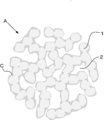
- the metal compound particle group A has a three-dimensional network structure.
- the three-dimensional network structure is a structure in which the primary particles 1 of a metal compound having a nano size are combined and connected in a network form, and a nano size void 2 exists. There is no grain boundary at the bonding interface of the primary particles 1, while many fine pores are present between the primary particles 1.
- the three-dimensional network structure forms an electron path for the negative electrode active material, the voids 2 serve as storage sites for the electrolytic solution, and the pores between the primary particles 1 serve as ion paths.
- the metal compound particles are particles capable of inserting and extracting lithium ions.
- the metal compound particles include FeO, Fe 2 O 3 , Fe 3 O 4 , MnO, MnO 2 , Mn 2 O 3 , Mn 3 O 4 , CoO, Co 3 O 4 , NiO, Ni 2 O 3 , TiO, and TiO 2.
- oxides such as TiO 2 (B), TiNb 2 O 7 , Nb 2 O 5 , CuO, NiO, SnO, SnO 2 , SiO 2 , RuO 2 , WO, WO 2 , WO 3 , MoO 3 , and ZnO, Metals such as Sn, Si, Al, Zn, LiVO 2 , Li 3 VO 4 , Li 4 Ti 5 O 12 , Sc 2 TiO 5 , Fe 2 TiO 5 , Li 2 Na 2 Ti 6 O 14 , Li 2 BaTi 6 O.
- composite oxides such as Li 2 SrTi 6 O 14, nitrides such as Li 2.6 Co 0.4 N, Ge 3 N 4 , Zn 3 N 2 and Cu 3 N, Y 2 Ti 2 O 5 S 2 , MoS 2 .
- the oxide or oxyacid salt containing lithium is represented by Li ⁇ M ⁇ Y ⁇ .
- M Co, Ni, Mn, Ti, Si, Sn, Al, Zn, Mg, Nb, or V
- Y O.
- M Fe, Mn, V, Co, or Ni
- Y PO 4 , SiO 4 , BO 3 , or P 2 O 7 .
- M ′ Fe, Co, Mn, V, Ti, or Ni.
- lithium iron phosphate, lithium titanate, lithium cobalt oxide, lithium vanadium phosphate, lithium iron manganese phosphate can be used.
- lithium titanate Li 4 Ti 5 O 12
- the porosity in the cross section of the three-dimensional network structure is preferably in the range of 7 to 50%.
- the porosity is less than 7%, the area in contact with the electrolytic solution is small, which affects the movement of ions in the electrolytic solution. Further, when the porosity exceeds 50%, the bonds between the primary particles 1 become rough and it becomes difficult to form a three-dimensional network structure.
- the average particle size of the primary particles 1 is in the range of 5 to 300 nm.
- the method of calculating the average particle size is as follows. First, the primary particles 1 are observed using a scanning electron microscope, and an image containing at least 150 primary particles 1 is photographed. The major axis and the minor axis of the elliptical image of the primary particle 1 included in one photographed visual field (image) are measured, and the average value of the major axis and the minor axis is calculated for each primary particle 1. Then, the average value of each primary particle 1 is added, and the added value is divided by the measured number of primary particles 1. This result falls within the range of 5 to 300 nm.
- the metal compound particles acquire many nano-sized pores.
- the area of the metal compound particles in contact with the electrolytic solution increases, and the movement of ions in the electrolytic solution becomes smooth.
- the pores of the metal compound particles were measured, many fine pores were present. In particular, it includes many fine pores of 40 nm or less.
- the differential pore volume was converted from the pore distribution measured by the nitrogen gas adsorption measurement method.
- the differential pore volume in the pore diameter range of 10 to 40 nm has a value of 0.01 cm 3 / g or more, and particularly a value of 0.02 cm 3 / g or more is obtained. Therefore, the larger the area in contact with the electrolytic solution and the larger the area in contact with the electrolytic solution, the better the discharge rate characteristic when used in the negative electrode.
- the coat layer C is formed on a part of the metal compound particle group A.
- the metal compound particles are preferably formed on at least a part of the surface.
- the coat layer C is a layer containing silicon oxide.
- the coat layer C may be formed on the surface of the metal compound particles that define the voids 2 of the metal compound particle group A. That is, the coat layer C may be formed not only on the outer peripheral surface side of the metal compound particle group A but also on the surface of the metal compound particles in the voids 2 in the internal structure of the metal compound particle group A. However, the coat layer C is not formed so as to fill the voids 2, and the voids 2 remain in the metal compound particle group A in which the coat layer C is formed.
- Such a metal compound particle group A has a pore volume change rate of more than 0.008 dV p / dr p for a pore size of 10 nm or less. Further, the metal compound particle group A in which the coating layer C containing silicon oxide is formed has a reduction rate of the integrated intensity of 25 with respect to the metal compound particle group in which the coating layer C containing silicon oxide is not formed. % Or more.
- the coating layer C is preferably formed such that the content of the Si element in the metal compound particle group A is 0.4 or more and 3.0 wt% or less.
- the increase rate of the internal resistance after that can be suitably suppressed. If it exceeds 3.0 wt%, the coating layer is excessive for suppressing the generation of deposits, and it is not possible to expect a further suppression effect of the increase rate of the internal resistance.
- the silicon oxide contained in the coat layer C has low crystallinity. That is, silicon oxide is amorphous and does not have a perfect crystal structure. It is considered that such an amorphous silicon oxide has a good bonding property with the metal compound particles. Therefore, the coat layer C containing the amorphous silicon oxide is not locally formed on the surface of the metal compound particles. That is, the surface of the metal compound particles is formed uniformly and clinging to the metal compound particles. Although the bonding state between silicon oxide and metal compound particles has not been analyzed, it is likely that the surface functional group of the metal compound particle and the silicon oxide are bonded by physical adsorption such as hydrogen adsorption or the surface functional group of the metal compound particle and silicon oxide. It is considered to be a chemical bond with the surface functional group of the product.
- the coat layer C contains about 1% or less of carbon in addition to silicon oxide. Therefore, it is presumed that the coat layer C contains a carbon compound or a component such as SiOC n H 2n + 1 or SiC.
- the metal compound particle group A as described above is used as an electrode material for a power storage device such as a hybrid capacitor or a lithium ion secondary battery.
- a power storage device such as a hybrid capacitor or a lithium ion secondary battery.
- the configuration of the hybrid capacitor using the metal compound particle group A of the present embodiment will be described below as an example.
- a lithium ion secondary battery is an example of a power storage device.
- a positive electrode and a negative electrode are opposed to each other via a separator to form an element, and the element is impregnated with an electrolytic solution.
- the lithium ion secondary battery is charged and discharged according to the direction of occlusion and release of lithium ions in the positive and negative electrodes.
- Each of the positive electrode and the negative electrode is formed by integrating a layer of an active material with a current collector.
- the positive electrode active material and the current collector, and the negative electrode active material and the current collector are bonded to each other via a binder using a pressure bonding method or a doctor blade method.
- the current collector is typically a conductive material such as aluminum, copper, iron, nickel, titanium, steel, or carbon. Particularly, aluminum or copper having high thermal conductivity and electronic conductivity is preferable.
- shape of the current collector any shape such as a film shape, a foil shape, a plate shape, a net shape, an expanded metal shape, and a cylindrical shape can be adopted.
- binder examples include rubbers such as fluorine rubber, diene rubber, and styrene rubber, fluoropolymers such as polytetrafluoroethylene and polyvinylidene fluoride, cellulose such as carboxymethyl cellulose and nitrocellulose, and other polyolefin resins, polyimide Examples thereof include resins, acrylic resins, nitrile resins, polyester resins, phenol resins, polyvinyl acetate resins, polyvinyl alcohol resins, epoxy resins and the like. These binders may be used alone or in combination of two or more.
- the positive electrode active material layer is formed by kneading LMO particles, carbon which is a conductive auxiliary agent, and a binder, and is combined with a current collector.
- the carbon can be used without particular limitation as long as it has conductivity, for example, Ketjen black, acetylene black, carbon black such as channel black, fullerene, carbon nanotubes, carbon nanofibers, amorphous carbon, carbon fibers, Examples thereof include natural graphite, artificial graphite, graphitized Ketjen black, mesoporous carbon, vapor grown carbon fiber and the like.
- binder known binders such as polytetrafluoroethylene, polyvinylidene fluoride (PVDF), tetrafluoroethylene-hexafluoropropylene copolymer, polyvinyl fluoride and carboxymethyl cellulose are used.
- the content of the binder is preferably 1 or more and 30 mass% or less with respect to the total amount of the electrode material.
- positive electrode active material may be added to this positive electrode active material layer.
- Other positive electrode active materials include layered rock salt type LiMO 2 , layered Li 2 MnO 3 -LiMO 2 solid solution, and spinel type LiM 2 O 4 (M in the formula is Fe, Co, Ni, a combination thereof, or a combination thereof. And Mn).
- positive electrode active materials other than the above include sulfur and sulfides such as Li 2 S, TiS 2 , MoS 2 , FeS 2 , VS 2 , Cr 1/2 V 1/2 S 2 , NbSe 3 , VSe 2 , In addition to selenides such as NbSe 3, oxides such as Cr 2 O 5 , Cr 3 O 8 , VO 2 , V 3 O 8 , V 2 O 5 , and V 6 O 13 , LiNi 0.8 Co 0.15 Al.
- sulfur and sulfides such as Li 2 S, TiS 2 , MoS 2 , FeS 2 , VS 2 , Cr 1/2 V 1/2 S 2 , NbSe 3 , VSe 2 .
- selenides such as NbSe 3
- oxides such as Cr 2 O 5 , Cr 3 O 8 , VO 2 , V 3 O 8 , V 2 O 5 , and V 6 O 13 , LiNi 0.8 Co 0.15 Al.
- the negative electrode active material is the above-mentioned metal compound particle group A, which is a metal compound particle group capable of inserting and extracting lithium ions.
- metal compound particle group A which is a metal compound particle group capable of inserting and extracting lithium ions.
- lithium titanate has an energy storage function by inserting / desorbing lithium ions. Since the volume change due to insertion / removal is about 1%, there is little capacity deterioration. Since the charge / discharge potential is about 1.55 V (vs. Li / Li +), side reactions such as decomposition of the electrolytic solution and precipitation of lithium metal due to rapid charge / discharge do not easily occur, and the cycle characteristics are excellent.
- Examples of the base separator include kraft, Manila hemp, esparto, hemp, rayon and other celluloses and their mixed papers, polyethylene terephthalate, polybutylene terephthalate, polyethylene naphthalate, polyester resins such as their derivatives, and polytetrafluoroethylene.
- -Based resin polyvinylidene fluoride-based resin, vinylon-based resin, aliphatic polyamide, semi-aromatic polyamide, polyamide-based resin such as wholly aromatic polyamide, polyimide-based resin, polyethylene resin, polypropylene resin, trimethylpentene resin, polyphenylene sulfide resin,
- a resin such as an acrylic resin may be used alone or in combination.
- the electrolyte of the electrolytic solution is a lithium salt that serves as a lithium ion source.
- the lithium salt include LiPF 6 , LiBF 4 , LiClO 4 , LiN (SO 2 CF 3 ) 2 , LiN (SO 2 C 2 F 5 ) 2 , CF 3 SO 3 Li, LiC (SO 2 CF 3 ) 3 , and LiPF 3 (C 2 F 5 ) 3 or a mixture thereof.
- the concentration of the lithium salt is generally in the range of 0.1 to 2.5 mol / L, preferably 0.5 to 2 mol / L.
- a quaternary ammonium salt may be added in addition to the lithium salt.
- the quaternary ammonium salt is added at a molar concentration of 1.6 M or more, but is not particularly limited, but is added at a molar concentration of 1 M, for example.
- Examples of the quaternary ammonium salt include tetraethylammonium, triethylmethylammonium, diethyldimethylammonium, ethyltrimethylammonium, methylethylpyrrolidinium, spirobipyrrolidinium, spiro- (N, N ′)-bipyrrolidinium and 1-ethyl as a cation.
- Examples thereof include -3-methylimidazolium, 1-ethyl-2,3-dimethylimidazolium, and the like.
- Anions include BF 4 ⁇ , PF 6 ⁇ , ClO 4 ⁇ , AsF 6 ⁇ , SbF 6 ⁇ , AlCl. 4 -, or RfSO 3 -, (RfSO 2) 2 N -, RfCO 2 - (Rf is a fluoroalkyl group having 1 to 8 carbon atoms), and the like.
- the following solvents are used as the electrolyte solvent. These solvents may be used alone or in combination of two or more. Examples thereof include cyclic carbonic acid ester, chain carbonic acid ester, phosphoric acid ester, cyclic ether, chained ether, lactone compound, chained ester, nitrile compound, amide compound, sulfone compound and the like. Examples of the cyclic carbonic acid ester include ethylene carbonate, propylene carbonate, butylene carbonate, 4-fluoro-1,3-dioxolan-2-one and 4- (trifluoromethyl) -1,3-dioxolan-2-one. Of these, ethylene carbonate and propylene carbonate are preferable.
- chain carbonic acid ester examples include dimethyl carbonate, ethyl methyl carbonate, diethyl carbonate, methyl n-propyl carbonate, methyl isopropyl carbonate, n-butyl methyl carbonate, diethyl carbonate, ethyl n-propyl carbonate, ethyl isopropyl carbonate, n-butyl ethyl.
- Carbonate, di-n-propyl carbonate, diisopropyl carbonate, di-n-butyl carbonate, fluoroethyl methyl carbonate, difluoroethyl methyl carbonate, trifluoroethyl methyl carbonate and the like can be mentioned, preferably dimethyl carbonate, ethyl methyl carbonate and diethyl carbonate. is there.
- Phosphonates include trimethyl phosphate, triethyl phosphate, ethyl dimethyl phosphate, diethyl methyl phosphate, etc.
- Examples of the cyclic ether include tetrahydrofuran and 2-methyltetrahydrofuran.
- Examples of the chain ether include dimethoxyethane and the like.
- Examples of the lactone compound include ⁇ -valerolactone and ⁇ -butyrolactone.
- Examples of the chain ester include methyl propionate, methyl acetate, ethyl acetate, methyl formate and the like.
- Examples of the nitrile compound include acetonitrile and the like.
- Examples of the amide compound include dimethylformamide.
- Examples of the sulfone compound include, but are not limited to, sulfolane, methylsulfolane, dimethylsulfone, ethylmethylsulfone, and isopropylsulf
- the method for producing a metal compound particle group according to the present invention has the following steps. (1) Mixing step of mixing the base metal compound particle group and the raw material of silicon oxide (2) Heating step of heating the powder obtained by the mixing step at 300 to 600 ° C.
- the metal compound particle group A of this embodiment is created based on the metal compound particle group serving as a base.
- the metal compound particle group serving as a base has a three-dimensional network structure. However, no coat layer was formed on the surface of the metal compound particle group.
- the metal compound particle group A of the present embodiment is manufactured by performing the treatment described in the above steps (1) and (2) using this metal compound particle group. Hereinafter, each step will be described in detail.
- the metal compound particle group serving as the base and the raw material of silicon oxide are mixed to prepare a mixed solution.
- a silane coupling agent containing a silicon atom can be used as a raw material of silicon oxide.
- a solvent is added to a mixture of the base metal compound particle group and the silane coupling agent to prepare a mixed solution.
- the silane coupling agent is preferably mixed in a ratio of 1 to 20 wt%, and more preferably 3 to 20 wt% with respect to the weight of the base metal compound particle group.
- the mixing amount of the silane coupling agent is less than 1 wt%, deposits are remarkably formed on the negative electrode material in the electricity storage device prepared using the metal compound particle group A. Therefore, the effect of suppressing the internal resistance cannot be obtained. Further, when the mixing amount of the silane coupling agent exceeds 20 wt%, the thickness of the coat layer C formed in the electricity storage device prepared using the metal compound particle group A increases.
- the mixing amount of the silane coupling agent is 3 to 20 wt%, the coating process in which the amount of Si element contained in the metal compound particle group A becomes 0.4 to 3.0 wt% by the heating process.
- the layer C is formed, and the increase rate of the internal resistance after charge / discharge can be suitably suppressed.
- the mixing amount of the silane coupling agent is 3 to 10 wt%, the amount of the Si element contained in the metal compound particle group A becomes 0.4 or more and 1.4 wt% or less through the heating process.
- the coat layer C is formed, the thickness of the coat layer C becomes appropriate, and the increase rate of the internal resistance after charging / discharging can be suitably suppressed, and the initial increase of the internal resistance of the electricity storage device can be suppressed.
- the silane coupling agent is not particularly limited, but a silane coupling agent composed of a compound represented by the following general formula or a salt thereof is typical.
- X 1 is an atomic group having a vinyl group, an amino group, an epoxy group, a chloro group, a mercapto group, a ketimine group, an acryloyl group, a methacroyl group, a styryl group, a phenyl group, an isocyanate group, an alkyl group or an alkoxy group.
- X 2 to X 4 are alkyl groups, alkoxy groups, chloro groups, hydroxyl groups)
- These silane coupling agents include tetraethoxysilane, vinyltrimethoxysilane, N- (2-aminoethyl) 3-aminopropyltrimethoxysilane, 3-aminopropyltriethoxysilane, and 3-glycidoxypropyltrimethoxy.
- Silane 2- (3,4-epoxycyclohexyl) ethyltrimethoxysilane, 3-acryloxypropyltrimethoxysilane, 3-methacryloxypropyltrimethoxysilane, 3-mercaptopropyltrimethoxysilane, N- [2- (vinyl Examples thereof include benzylamino) ethyl] -3-aminopropyltrimethoxysilane / hydrochloride.
- any liquid that does not adversely affect the reaction can be used without particular limitation, and water, methanol, ethanol, isopropyl alcohol, etc. can be preferably used. You may mix and use 2 or more types of solvents.
- the prepared mixed solution is sufficiently stirred using a homogenizer so that the metal compound particle group and the silane coupling agent are dispersed in the mixed solution.
- the silane coupling agent is attached to the surfaces and voids of the metal compound particle group serving as the base.
- the mixed solution after stirring is allowed to stand, the metal compound particle group and the silane coupling agent dispersed in the mixed solution are aggregated, and the mixed powder of the metal compound particle group and the silane coupling agent is recovered.
- an alkaline compound may be further added to the mixed solution.
- an alkaline compound By adding an alkaline compound, the amount of silicon oxide deposited relative to the amount of silicon oxide raw material added during the manufacturing process increases, and with a small amount of silane coupling agent added, the rate of increase in internal resistance after charging and discharging is increased. Can be suppressed more suitably.
- the amount of the raw material of the silicon oxide added in the manufacturing process can be reduced, leading to a reduction in cost.
- the reactivity of the metal compound particle group and the silane coupling agent is improved by the catalytic action of the alkali compound, and the silicon oxide is likely to be attached to the surface of the metal compound particle group. Conceivable. Therefore, the amount of silicon oxide attached to the amount of raw material of silicon oxide added in the manufacturing process increases, and the increase rate of internal resistance after charge and discharge is suppressed as compared with the case where no alkali compound is added. it is conceivable that.
- the amount of the alkali compound added is preferably in the range of 0.05 to 5 mmol with respect to 10 g of the metal compound particle group.
- Alkali metals and alkaline earth metals are, for example, lithium, sodium, potassium and calcium.
- examples of the inorganic alkaline agent include aqueous ammonia.
- examples of the organic alkaline agent include amines such as triethylamine, diethylamine, pyridine, and tetramethylguanidine. These alkaline compounds may be added alone or in combination of two or more.
- an alkaline compound preferable for addition such as a lithium salt
- the same kind as the raw material of the metal compound particle group or the electrolyte in the electrolytic solution which does not become an impurity in the characteristics of the metal compound particle group, or during the manufacturing process
- the metal compound particles are removed by the heat treatment, etc., and do not remain in the metal compound particle group.
- the metal compound particle group may be pretreated with the alkali compound and then the step of mixing with the silane coupling agent may be performed.
- the pretreatment step the alkali compound and the metal compound particle group are mixed with the solvent, and the mixture is filtered and dried. Then, the filtered and dried product is used to proceed to the mixing step. After mixing, the mixture may be left at 30 to 100 ° C. for 1 to 100 hours.
- the metal compound particle group is pretreated with an alkali compound as in this method, the increase rate of the internal resistance after charge and discharge can be suppressed more preferably.
- the solvent and alkali compound used in this method can be the same as those used in the method in which the alkali compound is further added to the mixed solution.
- the mixed powder obtained in the mixing step is subjected to heat treatment.
- the heat treatment may be performed in the temperature range of 300 to 600 ° C. for 1 to 24 hours. It is considered that in this heating step, silicon oxide derived from the silane coupling agent is produced in an amorphous state and is bonded to the metal compound particle group serving as the base.
- the aggregate obtained in the mixing step may be recovered and the aggregate may be dried. Drying is performed by heating, and it is preferable to heat the aggregate to 20 to 180 ° C. to dry it.
- the heating time is preferably 6 to 48 hours.
- the effects of the metal compound particle group A of the present embodiment and the electrode for an electricity storage device including the metal compound particle group A are as follows. (1) A metal compound particle group having a three-dimensional network structure in which metal compound particles are connected, and a coating layer containing a silicon oxide is formed on a part of the metal compound particle group.
- the coat layer C prevents the deposit from being generated on the negative electrode. Therefore, an increase in internal resistance of the electricity storage device can be suppressed.
- the coat layer C containing silicon oxide is formed on at least a part of the surface of the metal compound particles.
- the coat layer C is formed on the surface of the metal compound particles, it is possible to more reliably prevent the generation of deposits on the surface of the negative electrode. Therefore, an increase in internal resistance of the electricity storage device can be suppressed.
- the amount of Si element contained based on silicon oxide is 0.4 or more and 3.0 wt% or less with respect to the entire metal compound particle group A.
- the coat layer C is formed so that the amount of the Si element contained based on the silicon oxide is 0.4 or more and 3.0 wt% or less with respect to the entire metal compound particle group A. Can be provided with an appropriate thickness to suppress the increase rate of the internal resistance of the electricity storage device after charging and discharging.
- the amount of Si element contained based on silicon oxide is 0.4 or more and 1.7 wt% or less with respect to the entire metal compound particle group.
- the coating layer C is formed such that the amount of the Si element contained based on the silicon oxide is 0.4 or more and 1.7 wt% or less with respect to the entire metal compound particle group A.
- a more appropriate thickness can be provided to suppress the increase rate of the internal resistance of the electricity storage device after charging / discharging, and also suppress the increase of the initial internal resistance of the electricity storage device.
- the void 2 exists in the three-dimensional network structure, and the metal compound particles defining the void 2 have the coating layer C containing silicon oxide formed on the surface thereof.
- the coat layer C is formed not only on the outer peripheral surface of the metal compound particle A but also on the surface of the metal compound particle in the void 2 in the internal structure of the metal compound particle group A. By sufficiently forming the coat layer C to reach the void, it is possible to enhance the effect of suppressing the generation of deposits and the increase of internal resistance.
- the silicon oxide contained in the coat layer C is an amorphous silicon oxide.
- the bondability between the coat layer C and the metal compound particles is improved. Therefore, the metal compound particle group A in which the coat layer C is bonded uniformly and clinging to the metal compound particles is obtained.
- the coating layer C will not be dissolved by the electrolytic solution or the like. Therefore, in the electricity storage device, it is possible to reliably suppress the generation of deposits and the increase in internal resistance.
- the metal compound particle group having a pore volume change rate of more than 0.008 dV p / dr p with respect to the pore diameter of 10 nm or less the clogging of voids is eliminated. That is, the coat layer C is not formed so as to fill the voids. Therefore, it is possible to suppress an increase in the initial internal resistance.
- the reduction rate of the integrated intensity is 25% or more with respect to the metal compound particle group in which the coating layer containing silicon oxide is not formed.
- the integrated intensity ratio of the metal compound particle group in which the coat layer C is formed is lower than that of the metal compound particle group in which the coat layer containing silicon oxide is not coated.
- the coat layer C suppresses the generation of deposits on the negative electrode, and thus the increase in internal resistance can be suppressed.
- the components in the electrolytic solution react on the surface of the negative electrode and a fluorine-derived deposit is generated on the negative electrode. Be done. It is speculated that the metal compound particle group A of the present embodiment is particularly effective in suppressing the formation of these fluorine-derived deposits.
- a metal compound particle group serving as a base a mixing step of mixing a silicon oxide raw material, and a heating step of heating the powder obtained by the mixing step at 300 to 600 ° C.
- the coating layer C containing the silicon oxide derived from the raw material of the silicon oxide becomes the metal compound. Formed on the surface of particles.
- the silicon oxide becomes amorphous, and the bond with the metal compound particles is improved.
- the raw material of silicon oxide is mixed in a ratio of 1 to 20 wt% with respect to the weight of the metal compound particle group serving as the base.
- a suitable amount of coat layer C is formed on the metal compound particles. That is, it becomes possible to form the coat layer C capable of suppressing an increase in initial internal resistance and suppressing an increase in internal resistance after charging / discharging.
- the raw material of silicon oxide is mixed in a ratio of 3 to 20 wt% with respect to the weight of the metal compound particle group serving as the base.
- the amount of Si element contained in the metal compound particle group A becomes 0.4 or more and 3.0 wt% or less by heat treatment at 300 to 600 ° C. by mixing 3 to 20 wt% of the silicon oxide raw material.
- the coat layer C having a uniform thickness is formed, and the increase rate of the internal resistance after charge / discharge can be suitably suppressed.
- the raw material of silicon oxide is mixed in a ratio of 3 to 10 wt% with respect to the weight of the metal compound particle group serving as the base.
- the amount of Si element contained in the metal compound particle group A becomes 0.4 or more and 1.7 wt% or less by the heat treatment at 300 to 600 ° C.
- the coat layer C having an appropriate thickness is formed, and the increase rate of the internal resistance after charging / discharging can be suitably suppressed and the initial increase of the internal resistance of the electricity storage device can be suppressed.
- one or more alkaline compounds are further mixed.
- the alkali compound include alkali metal or alkaline earth metal hydroxides, acetates, sulfates, carbonates, nitrates, chlorides, inorganic alkali agents or organic alkali agents.
- the amount of silicon oxide adhered to the amount of the silicon oxide raw material added in the manufacturing process increases, and a small amount of the silane coupling agent is added to the material after charge and discharge.
- the increase rate of the internal resistance can be suppressed more preferably.
- the amount of the raw material of the silicon oxide added in the manufacturing process can be reduced, leading to a reduction in cost.
- the base metal compound particle group is pretreated with an alkali compound.
- Pretreatment of the metal compound particle group with an alkali compound makes it possible to more suitably suppress the increase rate of internal resistance after charge / discharge.
- the silane coupling agent was mixed in 5 wt% with respect to lithium titanate. In the mixing step, the mixture was stirred for 10 minutes at a rotation speed of 15,000 using a homogenizer. The aggregate after standing was collected and vacuum dried at 150 ° C. for 12 hours. Then, the dried powder was heat-treated at 400 ° C. for 3 hours.
- Example 2 In Example 2, 10 wt% of the silane coupling agent was mixed with lithium titanate. Other than that, it produced like Example 1.
- Example 3 the silane coupling agent was mixed in 20 wt% with respect to lithium titanate. Other than that, it produced like Example 1.
- Example 4 the silane coupling agent was mixed with lithium titanate at 3 wt%. Other than that, it produced like Example 1.
- Example 5 3-glycidoxypropyltrimethoxysilane containing an epoxy group as an organic functional group was used as a silane coupling agent, and was mixed at 3 wt% with respect to lithium titanate. Other than that, it produced like Example 1. That is, it differs from Example 4 in that the silane coupling agent is an epoxy type.
- Example 6 3-glycidoxypropyltrimethoxysilane was used as the silane coupling agent, and mixed at 5 wt% with respect to lithium titanate. Other than that, it produced like Example 1. That is, the silane coupling agent is an epoxy type as in Example 5, but the addition amount of the silane coupling agent is different from that in Example 5.
- Example 7 3-glycidoxypropyltrimethoxysilane was used as the silane coupling agent, and was mixed with lithium titanate at 10 wt%. Other than that, it produced like Example 1. That is, the silane coupling agent is an epoxy type as in Example 5, but the addition amount of the silane coupling agent is different from that in Example 5.
- Example 8 3-glycidoxypropyltrimethoxysilane was used as the silane coupling agent and mixed in 20 wt% with respect to lithium titanate. Other than that, it produced like Example 1. That is, the silane coupling agent is an epoxy type as in Example 5, but the addition amount of the silane coupling agent is different from that in Example 5.
- Example 9 3-glycidoxypropyltrimethoxysilane was used as the silane coupling agent, and was mixed at 3 wt% with respect to lithium titanate.
- lithium hydroxide was added as an alkali compound in addition to lithium titanate and a silane coupling agent, and a mixing step was performed.
- Lithium hydroxide was added at a ratio of 0.25 mmol to 10 g of lithium titanate. Other than that, it produced like Example 1. That is, it differs from Example 5 in that an alkaline compound is added.
- Example 10 3-glycidoxypropyltrimethoxysilane was used as the silane coupling agent, and was mixed in 5 wt% with respect to lithium titanate. Other than that, it produced like Example 9. That is, although the alkali compound was added as in Example 9, the addition amount of the silane coupling agent was different from that in Example 9.
- Example 11 3-glycidoxypropyltrimethoxysilane was used as the silane coupling agent and mixed with lithium titanate at 10 wt%. Other than that, it produced like Example 9. That is, although the alkali compound was added as in Example 9, the addition amount of the silane coupling agent was different from that in Example 9.
- Example 12 3-glycidoxypropyltrimethoxysilane was used as the silane coupling agent and mixed in 20 wt% with respect to lithium titanate. Other than that, it produced like Example 9. That is, although the alkali compound was added as in Example 9, the addition amount of the silane coupling agent was different from that in Example 9.
- Example 13 3-glycidoxypropyltrimethoxysilane was used as the silane coupling agent, and was mixed at 3 wt% with respect to lithium titanate.
- lithium hydroxide which is an alkali compound, water which is a solvent, and lithium titanate which is a metal compound particle group serving as a base are mixed and stirred with a stirrer for 30 minutes. After preserving at 60 ° C. for 64 hours, filtration, washing with water, and drying at 30 ° C. for 24 hours were pretreated. Lithium hydroxide was added at a ratio of 2.5 mmol to 10 g of lithium titanate. Other than that, it produced like Example 9. That is, compared with Example 9, the difference is that the metal compound particle group serving as the base is pretreated with an alkali compound.
- Comparative Example 1 In Comparative Example 1, the same treatment as in Example 1 was performed on lithium titanate without mixing the silane coupling agent.
- Comparative example 2 In Comparative Example 2, the silane coupling agent was not mixed. After the mixing step, only vacuum drying was performed, and no heat treatment was performed.
- Comparative example 3 (Comparative example 3)
- the silane coupling agent was mixed with lithium titanate in an amount of 5 wt%. After the mixing step, only vacuum drying was performed and no heat treatment was performed.
- Comparative example 4 In Comparative Example 4, 10 wt% of the silane coupling agent was mixed with lithium titanate. After the mixing step, only vacuum drying was performed and no heat treatment was performed.
- Comparative example 5 (Comparative example 5)
- the silane coupling agent was mixed in 20 wt% with respect to lithium titanate. After the mixing step, only vacuum drying was performed and no heat treatment was performed.
- Comparative example 6 (Comparative example 6)
- the silane coupling agent was mixed with lithium titanate in an amount of 3 wt%. After the mixing step, only vacuum drying was performed and no heat treatment was performed.
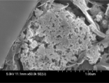
- FIG. 2 is an SEM image ( ⁇ 50.0K) of the lithium titanate particle group of Comparative Example 1.
- the lithium titanate particle group of Comparative Example 1 to which the silane coupling agent was not added has a three-dimensional network structure.
- the coat layer C is not formed on the outer peripheral surface of the lithium titanate particle group and the surface of the void.
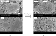
- FIG. 3 is an SEM image of the lithium titanate particle groups of Comparative Example 4 and Example 2.
- FIG. 3A is an SEM image of the lithium titanate particle group of Comparative Example 4, and the magnification is ⁇ 50.0K in the upper stage and ⁇ 100K in the lower stage.
- the silane coupling agent was mixed at 10 wt% and only dried, the outer peripheral surface of the lithium titanate particle group and the surfaces of the voids became the silane coupling agent. It looks like it is covered.
- the silane coupling agent adheres to the lithium titanate particle group so as to fill the voids of the lithium titanate particle group.
- FIG. 3 (b) is a SEM image of the lithium titanate particle group of Example 2, and the magnification is ⁇ 50.0K in the upper stage and ⁇ 100K in the lower stage.
- silane was formed on the outer peripheral surface of the lithium titanate particle group and the surface of the voids.
- a coat layer containing a silicon oxide derived from the coupling agent is formed. The coat layer is formed on the surface of the lithium titanate particles even in the voids of the lithium titanate particle group, but is not in a state of being formed so as to fill the voids.
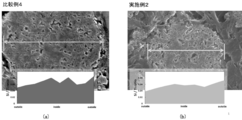
- FIG. 4A shows the analysis result of the lithium titanate particle group of Comparative Example 4
- FIG. 4B shows the analysis result of the lithium titanate particle group of Example 2.
- Elemental analysis was carried out so as to cross the diameter portion of the lithium titanate particle group as indicated by the arrow in the SEM image in each figure.
- the vertical axis plots the Si / Ti ratio to verify the proportion of Si derived from the silane coupling agent.
- a nitrogen gas adsorption measuring method is used as a measuring method. Specifically, nitrogen gas is introduced into the surfaces of the lithium titanate particles and the pores formed inside the lithium titanate particles, and the adsorption amount of the nitrogen gas is determined. Next, the pressure of the introduced nitrogen gas is gradually increased, the adsorption amount of nitrogen gas is plotted against each equilibrium pressure, and an adsorption isotherm curve is obtained. The measurement was performed using a high-precision gas / vapor adsorption amount measuring device BELSORP-max-N (manufactured by Bell Japan Ltd.).
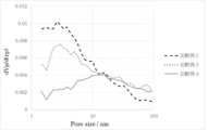
- FIG. 5 and 6 are graphs in which the horizontal axis represents the pore diameter and the vertical axis plots the pore volume change rate dV p / d (r p ).
- FIG. 5 shows pore size distribution data of Comparative Examples 2 to 4 which were not heated.
- Comparative Examples 3 and 4 in which the silane coupling agent was mixed, in comparison with Comparative Example 2 in which the silane coupling agent was not mixed, the voids of 10 nm or less were remarkably reduced. That is, it was found that in Comparative Examples 3 and 4 in which the silane coupling agent was mixed, the voids were filled with the silane coupling agent.
- FIG. 6 shows pore size distribution data of Comparative Example 1, Example 1 and Example 2 which were heated.
- Examples 1 and 2 in which the silane coupling agent was mixed have the same degree of voids as Comparative Example 1 in which the silane coupling agent is not mixed.
- the pore volume change rate of the pore diameter of 10 nm or less has a value exceeding 0.008 dV p / dr p .
- the rate of change in pore volume does not have to be uniformly over 0.008 for pore diameters of 10 nm or less, and may exceed 0.008 for some pores.
- the coating layer containing the silicon oxide derived from the silane coupling agent was formed, so that the clogging of the voids was eliminated. Do you get it.
- a lithium ion secondary battery was manufactured using the lithium titanate particles of Examples 1 to 4 and Comparative Examples 1 to 6. Specifically, 5% by weight of polyvinylidene fluoride and an appropriate amount of N-methylpyrrolidone are added to each particle group and sufficiently kneaded to form a slurry, which is applied onto an aluminum foil and dried to form a negative electrode.
- LMO particles, acetylene black as a conduction aid, and polyvinylidene fluoride (PVDF) as a binder were added to a solvent and stirred by a homogenizer to produce a slurry-like mixed solution.
- the sheet of the positive electrode active material layer obtained by applying this mixed solution to an aluminum current collector foil, drying and pressing was used as a positive electrode.
- An element was formed by interposing a cellulose separator between the positive electrode and the negative electrode, and the element was impregnated with an electrolytic solution.
- the electrolyte used was 1.6 molar LiBF 4 as a solute, and ⁇ -butyrolactone (GBL) was used as a solvent. Then, the element impregnated with the electrolytic solution was heat-sealed using a laminate film to manufacture lithium ion secondary batteries according to Examples 1 to 4 and Comparative Examples 1 to 6.
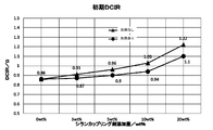
- FIG. 7 shows the results of measuring the initial internal resistance (DCIR) of the lithium ion secondary batteries of Examples 1 to 4 and Comparative Examples 1 to 6 thus created.
- the series connecting the plots with circles is the series that has undergone the heating process, and is the result of Comparative Example 1 and Examples 1 to 4, and the series connecting the plots with the triangles omits the heating process. It is a series of the above, and is composed of the results of Comparative Examples 2 to 6.
- Comparative Examples 3 to 6 in which the silane coupling agent is mixed are Comparative Examples in which the silane coupling agent is not mixed.
- the internal resistance was greatly increased compared to 2. Comparing the series of triangles and the series of circles, it was found that in each mixing ratio, the increase in internal resistance was suppressed in Examples 1 to 4 in which the heat treatment was performed. It is considered that in Comparative Examples 3 to 6 in which the heat treatment is not performed, the silane coupling agent fills the voids, so that the impregnation property of the electrolytic solution is lowered and the initial internal resistance is increased. Be done.
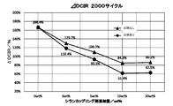
- FIG. 8 shows the rate of increase in internal resistance after 2000 cycles. The increase rate of the internal resistance was calculated from the internal resistance after charge / discharge / the initial internal resistance.
- the series connected with the circles is the series that has undergone the heating step, and is the result of Comparative Example 1 and Examples 1 to 4, and the series connected with the triangles has the heating step omitted. It is a series of the above, and is composed of the results of Comparative Examples 2 to 6.
- Comparative Examples 1 and 2 the rate of increase in internal resistance was 166.4%. In Comparative Examples 1 and 2, since the silane coupling agent was not mixed, deposits were formed on the negative electrode, and the internal resistance was significantly increased. Comparing the heat-treated Comparative Example 1 and Examples 1 to 4 with reference to the circled series, first, in Example 4 in which 3 wt% of the silane coupling agent was mixed, the increase rate was 118.4%. Yes, the rate of increase is suppressed as compared with Comparative Example 1. In addition, in Example 1 in which 5 wt% of the silane coupling agent was mixed, the increase rate was 93.3%, which is suppressed as compared with Comparative Example 1.
- Example 2 in which the silane coupling agent was mixed at 10 wt% was 61.2%, and the effect of suppressing the increase rate was enhanced.
- Example 3 in which 20 wt% of the silane coupling agent was mixed was 62.5%, which was slightly higher than that of Example 2. From this result, it was found that the effect of suppressing the increase rate was flat even when the silane coupling agent was mixed in an amount of 10 wt% or more.
- the silane coupling agent was mixed in excess of 20 wt%, the initial internal resistance was significantly increased. It was also found that when the silane coupling agent was mixed in an amount of 1 wt% or more, the formation of deposits was prevented and the increase in internal resistance after charge / discharge could be suppressed.
- the mixing amount of the silane coupling agent is set to 3 to 10% by weight, it is possible to suppress the increase in the initial internal resistance of the electricity storage device and to appropriately suppress the increase rate of the internal resistance after charging and discharging. It became clear that it was possible.
- Comparative Examples 2 to 6 in which the heat treatment is not performed are examined with reference to the series of triangular marks, Comparative Examples 3 to 6 in which the silane coupling agent is mixed are Comparative Examples in which the silane coupling agent is not mixed. Compared with No. 2, the increase rate of the internal resistance is decreased. Therefore, it was confirmed that the effect of suppressing the increase rate can be obtained by mixing the silane coupling agent.
- a lithium ion secondary battery was manufactured using the lithium titanate particles of Examples 5 to 8 prepared using an epoxy-based silane coupling agent as the negative electrode active material layer.
- the manufacturing method and manufacturing conditions of these lithium ion secondary batteries are the same as those of the lithium ion secondary batteries using the lithium titanate particles of Examples 1 to 4 and Comparative Examples 1 to 6.
- the initial stage of the lithium ion secondary battery using the lithium titanate particle group of Examples 5 to 8 The internal resistance (DCIR) and the increase rate of the internal resistance after 2000 cycles were measured.
- the method of measuring the initial internal resistance and the rate of increase of the internal resistance is the same as in Examples 1 to 4 and Comparative Example 1.
- FIG. 9 is a graph showing the relationship between the amount of silane coupling agent added and the initial internal resistance (DCIR).
- FIG. 10 is a graph showing the relationship between the amount of silane coupling agent added and the rate of increase in internal resistance. As shown in FIGS. 9 and 10, it was confirmed that the initial internal resistance (DCIR) and the increase rate of the internal resistance showed the same tendency as in Examples 1 to 4 even if the type of the silane coupling agent was changed. Was done.
- the silane coupling agent prevents deposit formation if it is mixed in an amount of 1 wt% or more. Then, it was confirmed that if the addition amount of the silane coupling agent was 20 wt% or less, the increase in the internal resistance due to the increase in the silane coupling agent was moderated regardless of the type of the silane coupling agent. Furthermore, by setting the mixing amount of the silane coupling agent to 3 to 10 wt%, the initial increase in the internal resistance of the electricity storage device is suppressed regardless of the type of the silane coupling agent, and the internal resistance after charge and discharge is increased. It has been clarified that the rate of increase can be suitably suppressed.
- a lithium ion secondary battery was manufactured using the lithium titanate particles of Examples 9 to 12 prepared while adding lithium hydroxide as a silane coupling agent and an alkaline compound as an active material layer of the negative electrode.
- the manufacturing method and manufacturing conditions of these lithium ion secondary batteries are the same as those of the lithium ion secondary batteries using the lithium titanate particles of Examples 1 to 8 and Comparative Examples 1 to 5.
- the initial stage of the lithium ion secondary battery using the lithium titanate particle group of Examples 9 to 12 was used.
- the internal resistance (DCIR) and the increase rate of the internal resistance after 2000 cycles were measured.
- the method of measuring the initial internal resistance and the increase rate of the internal resistance is the same as in Examples 1 to 8 and Comparative Example 1.
- FIG. 11 is a graph showing the relationship between the amount of silane coupling agent added and the initial internal resistance (DCIR).
- FIG. 12 is a graph showing the relationship between the amount of silane coupling agent added and the rate of increase in internal resistance.
- the initial internal resistance (DCIR) of the lithium titanate particles was higher than that in the case where the alkali compound was not added. It was confirmed that the value did not change or fell slightly.
- the increase rate of the internal resistance is higher than that in the case where the alkali compound is not added. It was confirmed that it was further suppressed.
- the addition amount of the silane coupling agent was 20 wt%, there was a difference of 6.9% in the increase rate of the internal resistance depending on whether or not the alkali compound was added.
- the increase rate of the internal resistance when the addition amount of the silane coupling agent is 20 wt% is the same as that when the addition amount of the silane coupling agent is not added and the addition amount of the silane coupling agent is 10 wt%.
- the addition amount of the silane coupling agent was 20 wt%.
- lithium hydroxide as an alkali compound
- a pretreatment such as filtration and drying was performed, and then lithium titanate of Example 13 produced using a silane coupling agent.
- the manufacturing method and manufacturing conditions of these lithium ion secondary batteries are the same as those of the lithium ion secondary batteries using the lithium titanate particles of Examples 1 to 8 and Comparative Examples 1 to 5.
- the initial internal resistance (DCIR) and the increase rate of the internal resistance after 2000 cycles were measured.
- the method of measuring the initial internal resistance and the increase rate of the internal resistance is the same as in Examples 1 to 8 and Comparative Example 1.
- Example 13 the results of the lithium ion secondary battery in which the lithium titanate particles of Example 9 are used as the active material layer of the negative electrode are also shown.
- Example 13 the lithium titanate particle group was pretreated with an alkali compound and then moved to the mixing step of the silane coupling agent, whereas in Example 9, the lithium titanate particle group, the alkali compound and the silane coupling agent were mixed.
- Example 9 and Example 13 differ in that the agent was mixed.
- Example 13 As shown in Table 1, almost no difference was found between Examples 9 and 13 in the initial internal resistance. However, in Example 13, the rate of increase in internal resistance after 2000 cycles was even better. That is, it was confirmed that the pretreatment of the metal compound particle group with the alkali compound further enhances the effect of suppressing the increase rate of the internal resistance.
- a mixed solvent was prepared by adding lithium titanate particles and a silane coupling agent (10 wt%) to isopropyl alcohol.
- the mixed solvent was stirred using a homogenizer, and the obtained aggregate was dried at 150 ° C. for 12 hours. No heat treatment was performed.
- the dried powder was washed 3 times with isopropyl alcohol. The washed powder was dried at 150 ° C. for 12 hours.
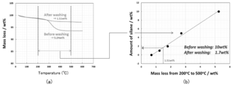
- Fig. 13 (a) shows the result of thermogravimetric measurement of the dried powder and the washed and dried powder. From FIG. 13A, in the powder before cleaning, the weight of 5.24 wt% is lost due to heating. On the other hand, in the powder dried after washing, the weight lost by heating was 1.51 wt%. When the loss amount of 1.51 wt% was converted into the amount of the silane coupling agent, it was 1.7 wt% as shown in FIG. 13 (b). That is, it was clarified that the silane coupling agent contained 10 wt% before the cleaning was reduced to 1.7 wt% after the cleaning. As described above, in Comparative Examples 3 to 6 in which the heat treatment was not performed, the silane coupling agent was dissolved in the solvent, so that it was found that the effect of suppressing the increase in internal resistance was low as described above.
- the amount of the silane coupling agent is 1.7 wt% with respect to the total amount of lithium titanate particles, the content of Si element contained in the lithium titanate particles will be 0.3 wt% by conversion. Therefore, from the results shown in FIG. 13, by adding 10 wt% of a silane coupling agent, a lithium titanate particle group containing Si element at a ratio of 0.3 wt% was produced when heat treatment was not performed. It can be said that it was done.
- the amount of Si element remaining in the lithium titanate particle groups of Examples 1 to 4 and Comparative Example 1 was measured.
- the alkali melting method was used as the method for quantifying the Si element. That is, the lithium titanate particles of Examples 1 to 4 and Comparative Example 1 and a flux were placed in a platinum crucible and melted by heating, and an acid was further added to the titanium of Examples 1 to 4 and Comparative Example 1. The lithium acid particle group was dissolved. Then, the amount of Si was quantified by ICP-AES (high frequency inductively coupled plasma optical emission spectroscopy). The result is shown in FIG.
- FIG. 14 is a graph showing the relationship between the amount of silane coupling agent added and the amount of Si element contained in the lithium titanate particle group.
- the silane coupling agent is added at 3 wt% or more and 20 wt% and heat treatment is performed after the mixing step as in Examples 1 to 4.
- a lithium titanate particle group having a Si element content of 0.4 wt% or more and 3.0 wt% or less can be produced, and it has been confirmed that this lithium titanate particle group can effectively suppress an increase in internal resistance.
- a silane coupling agent is added at 3 wt% or more and 10 wt% and heat treatment is performed after the mixing step as in Examples 1, 2, and 4.
- a lithium titanate particle group having a Si element content of 0.4 wt% or more and 1.4 wt% or less can be produced, and the initial internal resistance can also be suppressed by the lithium titanate particle group. ..
- FIG. 15A is a graph showing the carbon concentration (wt%) of the silane coupling agent at each heating temperature.
- FIG. 15B is a graph showing the silicon concentration (wt%) of the silane coupling agent at each heating temperature.
- FIG. 15C is a graph showing the carbon / silicon ratio at each heating temperature.
- the carbon content of the silane coupling agent decreased as the heating temperature increased.
- the heating temperature was 300 ° C.
- the carbon content was remarkably reduced and almost disappeared at 400 ° C.
- the silicon content of the silane coupling agent showed a substantially constant value regardless of the heating temperature.
- the heating step causes the carbon of the silane coupling agent to disappear, resulting in a structure very close to that of silicon oxide. It was speculated that That is, it was considered that when the silane coupling agent was heated at 300 to 600 ° C., it became a silicon oxide, not a silane coupling agent, and a coat layer was formed on the surface of the metal compound particle group.
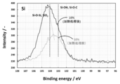
- FIG. 16 is a graph showing the results of measuring the lithium titanate particle group before the heat treatment and the lithium titanate particle group after the heat treatment.
- the binding energy of 103 eV indicates that Si—OH and Si—O—C are constituent functional groups.
- the binding energy of 104 eV indicates that Si—O—Si and SiO 2 are constituent functional groups.
- the spectrum of the lithium titanate particle group before heat treatment has a peak at an intermediate point between 103 eV and 104 eV.
- the peak shifts around 104 eV. That is, although it is considered that the lithium titanate particle group after the heat treatment also contains SiO and Si, it was found that the particles had a peak very close to that of SiO 2 .
- FIG. 17 shows the result of X-ray diffraction analysis performed on the lithium titanate particles after the heat treatment.
- SiO 2 has a peak near 24 degrees.
- the peak indicating SiO 2 did not appear. This is because the peak of SiO 2 detected at around 24 degrees by X-ray diffraction analysis is due to crystalline silicon oxide. That is, although a peak very close to SiO 2 was confirmed by X-ray photoelectron spectroscopy analysis, a peak indicating SiO 2 was not confirmed by X-ray diffraction analysis, so that the silicon oxide contained in the coat layer was amorphous. It turned out.
- FIG. 18 (a) shows solid-state 1 H-NMR data measured for the obtained lithium titanate particle groups of Example 2 and Comparative Example 1. The measurement was performed using a nuclear magnetic resonance analyzer (JNM-ECA600 manufactured by JEOL Ltd.). The peak existing at 5 to 8 ppm indicates the surface hydroxyl group (Bridge OH) of the lithium titanate particle group.
- Fig. 13 (b) shows the result of calculating the integrated intensity of the peak existing at 5 to 8 ppm in Fig. 18 (a) using the waveform separation software.
- FIG. 18B it is found that the integrated strength of the lithium titanate particle group of Example 2 is reduced by about 44% as compared with the integrated strength of the lithium titanate particle group of Comparative Example 1. It was That is, it is shown that the peak of the hydroxyl group (Bridge OH) existing on the surface of the lithium titanate particle group of Example 2 is reduced by the adhesion of the silicon compound. In other words, in Example 2, it is considered that about 44% of the surface of the lithium titanate particle group of Comparative Example 1 not coated with silicon oxide is coated with silicon oxide.
- FIG. 19 shows an increase rate of the internal resistance value after 2000 cycles of the lithium ion secondary batteries using the lithium titanate particle groups of Example 1, Example 2 and Comparative Example 1.
- Example 1 in which the reduction rate of integrated intensity is 29%
- Example 2 in which the reduction rate of integrated intensity is 44%
- the internal resistance after 2000 cycles is higher than that of the lithium ion secondary battery of Comparative Example 1.
- the rate of increase in value was suppressed, and good results were obtained. This is considered to be because the coating of the surface of the lithium titanate particles with the silicon oxide resulted in the suppression of deposit formation on the negative electrode.
- a reduction rate of the integrated strength of the lithium titanate particles of 25% or more is desirable from the viewpoint of suppressing the increase in internal resistance.
Landscapes
- Chemical & Material Sciences (AREA)
- Engineering & Computer Science (AREA)
- Electrochemistry (AREA)
- Chemical Kinetics & Catalysis (AREA)
- General Chemical & Material Sciences (AREA)
- Power Engineering (AREA)
- Materials Engineering (AREA)
- Composite Materials (AREA)
- Manufacturing & Machinery (AREA)
- Microelectronics & Electronic Packaging (AREA)
- Inorganic Chemistry (AREA)
- Battery Electrode And Active Subsutance (AREA)
- Electric Double-Layer Capacitors Or The Like (AREA)
- Inorganic Compounds Of Heavy Metals (AREA)
- Secondary Cells (AREA)
Abstract
L'invention concerne : un groupe de particules de composé métallique capable de supprimer une augmentation de la résistance interne d'un dispositif de stockage d'énergie ; une électrode contenant un groupe de particules de composé métallique pour un dispositif de stockage d'énergie ; et une méthode de production d'un groupe de particules de composé métallique. Le groupe de particules de composé métallique a une structure de réseau tridimensionnel dans laquelle des particules de composé métallique sont connectées les unes aux autres, une couche de revêtement C contenant de l'oxyde de silicium étant formée sur une partie du groupe de particules de composé métallique. La couche de revêtement C contenant de l'oxyde de silicium est formée sur au moins une partie de la surface des particules de composé métallique. Des vides 2 sont présents dans la structure de réseau tridimensionnel, et la couche de revêtement C contenant de l'oxyde de silicium est formée sur la surface de particules de composé métallique définissant les vides 2. L'oxyde de silicium contenu dans la couche de revêtement C est un oxyde de silicium amorphe.
Priority Applications (4)
| Application Number | Priority Date | Filing Date | Title |
|---|---|---|---|
| EP19887429.9A EP3885316A4 (fr) | 2018-11-22 | 2019-11-18 | Groupe de particules de composé métallique, électrode pour dispositif de stockage d'énergie, dispositif de stockage d'énergie et méthode de production d'un groupe de particules de composé métallique |
| CN201980076658.1A CN113165898A (zh) | 2018-11-22 | 2019-11-18 | 金属化合物粒子群、蓄电装置用电极、蓄电装置、及金属化合物粒子群的制造方法 |
| US17/294,413 US20220077463A1 (en) | 2018-11-22 | 2019-11-18 | Metal compound particle group, electrode for power storage device, power storage device, and method for producing metal compound particle group |
| JP2020558398A JP7640265B2 (ja) | 2018-11-22 | 2019-11-18 | 蓄電デバイス、および金属化合物粒子群の製造方法 |
Applications Claiming Priority (2)
| Application Number | Priority Date | Filing Date | Title |
|---|---|---|---|
| JP2018218931 | 2018-11-22 | ||
| JP2018-218931 | 2018-11-22 |
Publications (1)
| Publication Number | Publication Date |
|---|---|
| WO2020105603A1 true WO2020105603A1 (fr) | 2020-05-28 |
Family
ID=70773283
Family Applications (1)
| Application Number | Title | Priority Date | Filing Date |
|---|---|---|---|
| PCT/JP2019/045151 Ceased WO2020105603A1 (fr) | 2018-11-22 | 2019-11-18 | Groupe de particules de composé métallique, électrode pour dispositif de stockage d'énergie, dispositif de stockage d'énergie et méthode de production d'un groupe de particules de composé métallique |
Country Status (5)
| Country | Link |
|---|---|
| US (1) | US20220077463A1 (fr) |
| EP (1) | EP3885316A4 (fr) |
| JP (1) | JP7640265B2 (fr) |
| CN (1) | CN113165898A (fr) |
| WO (1) | WO2020105603A1 (fr) |
Cited By (5)
| Publication number | Priority date | Publication date | Assignee | Title |
|---|---|---|---|---|
| CN114079051A (zh) * | 2020-08-18 | 2022-02-22 | 财团法人工业技术研究院 | 负极活性材料、负极以及电池 |
| JP2023549271A (ja) * | 2020-12-09 | 2023-11-22 | 横店集団東磁股▲ふん▼有限公司 | 軟磁性粉末、およびその調製方法及び使用 |
| WO2023233692A1 (fr) * | 2022-05-30 | 2023-12-07 | 株式会社 東芝 | Électrode, batterie secondaire et bloc-batterie |
| JP2024037659A (ja) * | 2022-09-07 | 2024-03-19 | 株式会社東芝 | ニオブチタン系酸化物、電極、二次電池、電池パック、車両、及び定置用電源 |
| JP2024043858A (ja) * | 2022-09-20 | 2024-04-02 | 株式会社東芝 | 二次電池、電池パック、車両及び定置用電源 |
Families Citing this family (1)
| Publication number | Priority date | Publication date | Assignee | Title |
|---|---|---|---|---|
| CN116072875B (zh) * | 2023-03-07 | 2023-06-16 | 宁德新能源科技有限公司 | 正极片、二次电池和电子设备 |
Citations (6)
| Publication number | Priority date | Publication date | Assignee | Title |
|---|---|---|---|---|
| JP2012199101A (ja) * | 2011-03-22 | 2012-10-18 | Dowa Holdings Co Ltd | リチウム−遷移金属複合酸化物粉末及びその製造方法並びに該粉末を用いた全固体リチウム電池用正極活物質 |
| WO2015072359A1 (fr) * | 2013-11-15 | 2015-05-21 | 住友金属鉱山株式会社 | Procédé de production de particules d'oxyde traitées en surface et particules d'oxyde produites par ledit procédé de production |
| JP2015185337A (ja) * | 2014-03-24 | 2015-10-22 | 日本碍子株式会社 | 全固体電池 |
| JP2015185237A (ja) * | 2014-03-20 | 2015-10-22 | パナソニックIpマネジメント株式会社 | 全固体リチウム二次電池用正極及びそれを用いた全固体リチウム二次電池 |
| JP2015189608A (ja) | 2014-03-27 | 2015-11-02 | 東ソー株式会社 | マンガン酸リチウム製造用二酸化マンガン及びその製造方法 |
| US20180287156A1 (en) * | 2015-10-07 | 2018-10-04 | GM Global Technology Operations LLC | Modification of lithium titanate electrode particles to eliminate gas formation in cell operation |
Family Cites Families (7)
| Publication number | Priority date | Publication date | Assignee | Title |
|---|---|---|---|---|
| JP2008016446A (ja) * | 2006-06-09 | 2008-01-24 | Canon Inc | 粉末材料、粉末材料を用いた電極構造体及び該電極構造体を有する蓄電デバイス、並びに粉末材料の製造方法 |
| JP2009164104A (ja) * | 2007-09-06 | 2009-07-23 | Canon Inc | 負極用電極材料、その製造方法ならびに該材料を用いた電極構造体及び蓄電デバイス |
| JP5659696B2 (ja) * | 2009-12-24 | 2015-01-28 | ソニー株式会社 | リチウムイオン二次電池、リチウムイオン二次電池用負極、電動工具、電気自動車および電力貯蔵システム |
| US10490316B2 (en) * | 2015-03-31 | 2019-11-26 | Nippon Chemi-Con Corporation | Titanium oxide particles, titanium oxide particle production method, power storage device electrode including titanium oxide particles, and power storage device provided with electrode including titanium oxide particles |
| JP6834187B2 (ja) * | 2016-06-22 | 2021-02-24 | 日本ケミコン株式会社 | ハイブリッドキャパシタ及びその製造方法 |
| JP6873614B2 (ja) * | 2016-06-22 | 2021-05-19 | 日本ケミコン株式会社 | リチウムイオン二次電池及びその製造方法 |
| CN106129465B (zh) * | 2016-08-10 | 2019-09-20 | 中国科学院西安光学精密机械研究所 | 一种掺氟锂离子固体电解质及其制备方法 |
-
2019
- 2019-11-18 WO PCT/JP2019/045151 patent/WO2020105603A1/fr not_active Ceased
- 2019-11-18 US US17/294,413 patent/US20220077463A1/en not_active Abandoned
- 2019-11-18 CN CN201980076658.1A patent/CN113165898A/zh active Pending
- 2019-11-18 JP JP2020558398A patent/JP7640265B2/ja active Active
- 2019-11-18 EP EP19887429.9A patent/EP3885316A4/fr active Pending
Patent Citations (6)
| Publication number | Priority date | Publication date | Assignee | Title |
|---|---|---|---|---|
| JP2012199101A (ja) * | 2011-03-22 | 2012-10-18 | Dowa Holdings Co Ltd | リチウム−遷移金属複合酸化物粉末及びその製造方法並びに該粉末を用いた全固体リチウム電池用正極活物質 |
| WO2015072359A1 (fr) * | 2013-11-15 | 2015-05-21 | 住友金属鉱山株式会社 | Procédé de production de particules d'oxyde traitées en surface et particules d'oxyde produites par ledit procédé de production |
| JP2015185237A (ja) * | 2014-03-20 | 2015-10-22 | パナソニックIpマネジメント株式会社 | 全固体リチウム二次電池用正極及びそれを用いた全固体リチウム二次電池 |
| JP2015185337A (ja) * | 2014-03-24 | 2015-10-22 | 日本碍子株式会社 | 全固体電池 |
| JP2015189608A (ja) | 2014-03-27 | 2015-11-02 | 東ソー株式会社 | マンガン酸リチウム製造用二酸化マンガン及びその製造方法 |
| US20180287156A1 (en) * | 2015-10-07 | 2018-10-04 | GM Global Technology Operations LLC | Modification of lithium titanate electrode particles to eliminate gas formation in cell operation |
Non-Patent Citations (1)
| Title |
|---|
| See also references of EP3885316A4 |
Cited By (10)
| Publication number | Priority date | Publication date | Assignee | Title |
|---|---|---|---|---|
| CN114079051A (zh) * | 2020-08-18 | 2022-02-22 | 财团法人工业技术研究院 | 负极活性材料、负极以及电池 |
| US20220059811A1 (en) * | 2020-08-18 | 2022-02-24 | Industrial Technology Research Institute | Negative electrode active material, negative electrode and battery |
| JP2022034555A (ja) * | 2020-08-18 | 2022-03-03 | 財團法人工業技術研究院 | 負極活物質、負極および電池 |
| CN114079051B (zh) * | 2020-08-18 | 2024-12-27 | 财团法人工业技术研究院 | 负极活性材料、负极以及电池 |
| JP2023549271A (ja) * | 2020-12-09 | 2023-11-22 | 横店集団東磁股▲ふん▼有限公司 | 軟磁性粉末、およびその調製方法及び使用 |
| JP7603811B2 (ja) | 2020-12-09 | 2024-12-20 | 横店集団東磁股▲ふん▼有限公司 | 軟磁性粉末、およびその調製方法及び使用 |
| WO2023233692A1 (fr) * | 2022-05-30 | 2023-12-07 | 株式会社 東芝 | Électrode, batterie secondaire et bloc-batterie |
| JPWO2023233692A1 (fr) * | 2022-05-30 | 2023-12-07 | ||
| JP2024037659A (ja) * | 2022-09-07 | 2024-03-19 | 株式会社東芝 | ニオブチタン系酸化物、電極、二次電池、電池パック、車両、及び定置用電源 |
| JP2024043858A (ja) * | 2022-09-20 | 2024-04-02 | 株式会社東芝 | 二次電池、電池パック、車両及び定置用電源 |
Also Published As
| Publication number | Publication date |
|---|---|
| JP7640265B2 (ja) | 2025-03-05 |
| EP3885316A1 (fr) | 2021-09-29 |
| US20220077463A1 (en) | 2022-03-10 |
| CN113165898A (zh) | 2021-07-23 |
| EP3885316A4 (fr) | 2022-05-04 |
| JPWO2020105603A1 (ja) | 2021-10-21 |
Similar Documents
| Publication | Publication Date | Title |
|---|---|---|
| KR102633418B1 (ko) | 비수전해질 이차 전지용 부극 활물질 및 비수전해질 이차 전지, 그리고 비수전해질 이차 전지용 부극재의 제조 방법 | |
| JP7640265B2 (ja) | 蓄電デバイス、および金属化合物粒子群の製造方法 | |
| US10593992B2 (en) | Negative electrode for potassium ion secondary batteries, negative electrode for potassium ion capacitors, potassium ion secondary battery, potassium ion capacitor, and binder for negative electrodes of potassium ion secondary batteries or negative electrodes of potassium ion capacitors | |
| KR102719294B1 (ko) | 부극 활물질, 혼합 부극 활물질 재료, 비수 전해질 이차 전지용 부극, 리튬 이온 이차 전지, 부극 활물질의 제조 방법 및 리튬 이온 이차 전지의 제조 방법 | |
| JP6112858B2 (ja) | 非水電解質二次電池 | |
| JP6253411B2 (ja) | リチウム二次電池 | |
| JP6873614B2 (ja) | リチウムイオン二次電池及びその製造方法 | |
| JP6903260B2 (ja) | リチウムイオン二次電池用負極及びリチウムイオン二次電池 | |
| US20140234704A1 (en) | Lithium secondary battery | |
| JP2010050079A (ja) | 非水電解質二次電池 | |
| KR20120129926A (ko) | 정극 재료, 그 제조 방법, 비수 이차 전지용 정극 및 비수 이차 전지 | |
| KR102759833B1 (ko) | 부극 활물질, 혼합 부극 활물질 재료, 비수 전해질 이차 전지용 부극, 리튬 이온 이차 전지, 부극 활물질의 제조 방법 및 리튬 이온 이차 전지의 제조 방법 | |
| WO2022270539A1 (fr) | Particules de carbone composites et leur utilisation | |
| JP2009245940A (ja) | 非水電解質二次電池 | |
| JP2016024879A (ja) | 非水電解質二次電池用正極、非水電解質二次電池およびそのシステム | |
| JP7262419B2 (ja) | 非水系電解質二次電池用正極活物質、および非水系電解質二次電池 | |
| WO2014010476A1 (fr) | Électrode destinée à une batterie rechargeable au lithium, son procédé de fabrication, batterie rechargeable au lithium et son procédé de fabrication | |
| JP6443416B2 (ja) | 非水電解液二次電池の製造方法、および非水電解液二次電池 | |
| WO2020026486A1 (fr) | Matériau d'électrode positive et batterie secondaire | |
| WO2013128559A1 (fr) | Batterie rechargeable lithium-ion | |
| JP6163920B2 (ja) | 電池の製造方法 | |
| WO2026001073A1 (fr) | Matériau composite à base de silicium, batterie secondaire et dispositif électronique | |
| JP6508049B2 (ja) | リチウムイオン二次電池用負極、リチウムイオン二次電池及びその製造方法 | |
| JP5472952B1 (ja) | 非水二次電池 | |
| WO2022215126A1 (fr) | Matériau d'électrode négative pour batterie secondaire au lithium-ion, électrode négative pour batterie secondaire au lithium-ion et batterie secondaire au lithium-ion |
Legal Events
| Date | Code | Title | Description |
|---|---|---|---|
| 121 | Ep: the epo has been informed by wipo that ep was designated in this application |
Ref document number: 19887429 Country of ref document: EP Kind code of ref document: A1 |
|
| ENP | Entry into the national phase |
Ref document number: 2020558398 Country of ref document: JP Kind code of ref document: A |
|
| NENP | Non-entry into the national phase |
Ref country code: DE |
|
| ENP | Entry into the national phase |
Ref document number: 2019887429 Country of ref document: EP Effective date: 20210622 |