WO2020110264A1 - 質量分析装置 - Google Patents
質量分析装置 Download PDFInfo
- Publication number
- WO2020110264A1 WO2020110264A1 PCT/JP2018/044042 JP2018044042W WO2020110264A1 WO 2020110264 A1 WO2020110264 A1 WO 2020110264A1 JP 2018044042 W JP2018044042 W JP 2018044042W WO 2020110264 A1 WO2020110264 A1 WO 2020110264A1
- Authority
- WO
- WIPO (PCT)
- Prior art keywords
- ion
- mass spectrometer
- vacuum chamber
- opening
- intermediate vacuum
- Prior art date
- Legal status (The legal status is an assumption and is not a legal conclusion. Google has not performed a legal analysis and makes no representation as to the accuracy of the status listed.)
- Ceased
Links
Images


Classifications
-
- H—ELECTRICITY
- H01—ELECTRIC ELEMENTS
- H01J—ELECTRIC DISCHARGE TUBES OR DISCHARGE LAMPS
- H01J49/00—Particle spectrometers or separator tubes
- H01J49/02—Details
- H01J49/06—Electron- or ion-optical arrangements
- H01J49/067—Ion lenses, apertures, skimmers
-
- H—ELECTRICITY
- H01—ELECTRIC ELEMENTS
- H01J—ELECTRIC DISCHARGE TUBES OR DISCHARGE LAMPS
- H01J49/00—Particle spectrometers or separator tubes
- H01J49/02—Details
- H01J49/04—Arrangements for introducing or extracting samples to be analysed, e.g. vacuum locks; Arrangements for external adjustment of electron- or ion-optical components
- H01J49/0431—Arrangements for introducing or extracting samples to be analysed, e.g. vacuum locks; Arrangements for external adjustment of electron- or ion-optical components for liquid samples
-
- H—ELECTRICITY
- H01—ELECTRIC ELEMENTS
- H01J—ELECTRIC DISCHARGE TUBES OR DISCHARGE LAMPS
- H01J49/00—Particle spectrometers or separator tubes
- H01J49/02—Details
- H01J49/06—Electron- or ion-optical arrangements
- H01J49/062—Ion guides
- H01J49/063—Multipole ion guides, e.g. quadrupoles, hexapoles
-
- H—ELECTRICITY
- H01—ELECTRIC ELEMENTS
- H01J—ELECTRIC DISCHARGE TUBES OR DISCHARGE LAMPS
- H01J49/00—Particle spectrometers or separator tubes
- H01J49/02—Details
- H01J49/10—Ion sources; Ion guns
- H01J49/16—Ion sources; Ion guns using surface ionisation, e.g. field-, thermionic- or photo-emission
- H01J49/165—Electrospray ionisation
-
- H—ELECTRICITY
- H01—ELECTRIC ELEMENTS
- H01J—ELECTRIC DISCHARGE TUBES OR DISCHARGE LAMPS
- H01J49/00—Particle spectrometers or separator tubes
- H01J49/02—Details
- H01J49/24—Vacuum systems, e.g. maintaining desired pressures
Definitions
- the present invention relates to a mass spectrometer, and more particularly to a mass spectrometer in which an ion source is an atmospheric pressure ion source and a mass separator is a quadrupole mass filter.
- the mass spectrometer according to the present invention is particularly suitable for a liquid chromatograph mass spectrometer (LC-MS) in which a mass spectrometer is connected to an outlet of a column of a liquid chromatograph (LC).
- LC-MS liquid chromatograph mass spectrometer
- a mass spectrometer used as a detector of a liquid chromatograph (LC) generally uses an electrospray ionization (ESI) method, an atmospheric pressure chemical ionization (APCI) method, and an atmospheric pressure light in order to ionize components in a liquid sample.
- An atmospheric pressure ion source according to an ionization method such as an ionization (APPI) method is provided.
- a mass spectrometer it is necessary to transport ions generated under an atmospheric pressure atmosphere to an analysis chamber in which a mass separator such as a quadrupole mass filter is arranged, and keep the analysis chamber in a high vacuum atmosphere.
- a configuration of a multistage differential evacuation system in which a plurality of intermediate vacuum chambers are provided between the ionization chamber and the analysis chamber is adopted.
- a plurality of compartments with different pressures are connected in series, so the ion path from the ion source to the ion detector is long, and the size of the instrument is large. Tends to grow.
- miniaturization of a mass spectrometer is realized by miniaturizing some of the elements constituting the mass spectrometer and appropriately changing control parameters such as applied voltage according to the miniaturization.
- the ion injection of the ion detector from the opening (atmospheric pressure orifice) for taking in ions from the ionization chamber in the atmospheric pressure atmosphere to the first intermediate vacuum chamber at the next stage.
- the length of the ion path to the surface is 400 mm or less, and the inner diameter of the atmospheric pressure orifice is 0.3 mm ⁇ or less.
- the internal volumes of the intermediate vacuum chambers and the analysis chambers are also appropriately determined.
- Patent Documents 1 and 2 have the following problems.
- the capacity of the rotary pump can be reduced as described above, but from the ionization chamber to the first intermediate vacuum chamber. It is more likely that the ions will be less likely to be introduced and will disappear during the process. Therefore, the amount of ions used for analysis decreases, which may lead to a decrease in detection sensitivity. Further, in the atmospheric pressure ion source, even small sample droplets try to pass through the ion introduction opening, but the smaller the diameter of the ion introduction opening, the easier it is to clog, which makes it more difficult for the ions to pass and decreases the detection sensitivity. The detection output may become unstable. In addition, it is necessary to increase the frequency of maintenance such as cleaning in order to eliminate clogging of the ion introduction opening, which not only increases the maintenance cost of the device but also lengthens the period during which the device cannot be used.
- the conventional small-sized mass spectrometer is designed to be downsized while sacrificing detection sensitivity and maintainability to some extent.
- the present invention has been made to solve these problems, and an object thereof is to provide a vacuum pump while maintaining performance and maintainability comparable to or close to those of a conventional mass spectrometer of a general size.
- An object of the present invention is to provide a compact mass spectrometer that can reduce the size and installation area of the device including
- the present inventor repeated the experiment and investigated under what conditions the ionic strength was increased. As a result, it was found that when the area of the ion introduction opening is large, the ion intensity becomes higher when the pressure in the first intermediate vacuum chamber is made lower than when it is small. It was found that the ion intensity can be maximized or close to that for ion introduction openings having various opening areas by setting the product of the pressure inside the room to fall within a predetermined range. In addition, the ability (evacuation speed) of the vacuum pump to maintain the pressure (vacuum degree) determined according to such conditions is sufficiently lower than the vacuum pump used in the conventional general mass spectrometer. I also confirmed that it would be enough. The present inventor has arrived at the present invention based on these findings and verifications.
- the mass spectrometer made to solve the above problems,
- An atmospheric pressure ion source for ionizing components in a liquid sample A first intermediate vacuum chamber that is arranged next to the atmospheric pressure ion source and that is evacuated by a first vacuum pump;
- An ion guide disposed inside the first intermediate vacuum chamber for transporting ions while converging by the action of a high frequency electric field;
- a high-vacuum analysis chamber that is disposed further downstream of the first intermediate vacuum chamber and is evacuated by a second vacuum pump or by both the second vacuum pump and the first vacuum pump;
- a mass separator disposed inside the analysis chamber for separating ions according to a mass-to-charge ratio;
- An ion detector disposed inside the analysis chamber, for detecting ions separated by the mass separator, Equipped with The opening area of the first opening is 0.071 mm 2 or more, and the product of the opening area of the first opening
- the pressure in the first intermediate vacuum chamber is generally set so that the ion intensity detected by the ion detector is as high as possible. If you want to reduce the size of the pump by suppressing its capacity, you can allow the ionic strength to fall slightly below its maximum value, that is, if the ionic strength is within the allowable threshold, 1 It is desirable to keep the pressure in the intermediate vacuum chamber high.
- An atmospheric pressure ion source for ionizing components in a liquid sample A first intermediate vacuum chamber that is arranged next to the atmospheric pressure ion source and that is evacuated by a first vacuum pump; An ion guide disposed inside the first intermediate vacuum chamber for transporting ions while converging by the action of a high frequency electric field; A first opening for introducing ions generated by the atmospheric pressure ion source into the first intermediate vacuum chamber; A high-vacuum analysis chamber that is disposed further downstream of the first intermediate vacuum chamber and is evacuated by a second vacuum pump or by both the second vacuum pump and the first vacuum pump; A mass separator disposed inside the analysis chamber for separating ions according to a mass-to-charge ratio; An ion detector disposed inside the analysis chamber, for detecting ions separated by the mass separator, And the opening area of the first opening is 0.071 mm 2 or more,
- the first vacuum pump for forming the first-stage vacuum region is a rotary pump
- the second vacuum pump for forming subsequent vacuum regions has an ultimate pressure by vacuum exhaust. It is a lower turbo molecular pump.
- the rotary pump is connected to the mass spectrometer main body via piping such as a hose, the rotary pump main body is often installed at a position away from the space where the mass spectrometer main body is installed.
- the turbo molecular pump is directly connected to and integrated with the mass spectrometer main body, a large size of the turbo molecular pump occupies a large space for installing the mass spectrometer. Therefore, in order to reduce the space for installing the mass spectrometer, it is desirable to reduce the size of the turbo molecular pump as much as possible.
- An atmospheric pressure ion source for ionizing components in a liquid sample A first intermediate vacuum chamber that is arranged at the next stage of the atmospheric pressure ion source and is evacuated by a first vacuum pump through a pipe; A second intermediate vacuum chamber that is arranged at a stage next to the first intermediate vacuum chamber and is evacuated by the turbo molecular pump through a first port of the turbo molecular pump; An analysis chamber which is arranged further downstream of the second intermediate vacuum chamber and which is evacuated by the turbo molecular pump through a second port of the turbo molecular pump; A mass separator disposed inside the analysis chamber for separating ions according to a mass-to-charge ratio; An ion detector disposed inside the analysis chamber, for detecting ions separated by the mass separator, A first opening for introducing ions generated by the atmospheric pressure ion source into the first intermediate vacuum chamber; A second opening for introducing ions
- the atmospheric pressure ion source in the present invention is an ion source that uses an ionization method such as an electrospray ionization method, an atmospheric pressure chemical ionization method, or an atmospheric pressure photoionization method.
- an ionization method such as an electrospray ionization method, an atmospheric pressure chemical ionization method, or an atmospheric pressure photoionization method.
- the first opening in the present invention is an opening of a thin tube called a desolvation tube or a heating capillary, or an orifice formed at the top of a sampling cone having a substantially conical shape.
- the opening area of the first opening is the area of the portion having the smallest cross-sectional area in the opening cross section in the longitudinal direction of the thin tube (that is, the most when the ion passes through). The area of the narrow part).
- the openings are on the ionization chamber side.
- one or two intermediate vacuum chambers are usually provided between the first intermediate vacuum chamber and the analysis chamber, and in the third aspect of the present invention, Two or more intermediate vacuum chambers are usually provided between one intermediate vacuum chamber and the analysis chamber. Then, in the intermediate vacuum chambers, as in the first intermediate vacuum chamber, an ion guide for transporting while converging the ions by the action of the high frequency electric field is arranged.
- the diameter of the opening is larger than the diameter (maximum 0.3 mm ⁇ ) of the ion introduction opening in the conventional small-sized mass spectrometer described above.
- the pressure in the first intermediate vacuum chamber is appropriately set so that high ion intensity can be obtained even under the condition that the opening area of the first opening is relatively large.
- the diameter of the circular first opening is 0.4 mm ⁇ (opening area: 0.126 mm 2 ), and the product of the opening area of the first opening and the pressure in the first intermediate vacuum chamber is
- the first vacuum pump having the ability to maintain the pressure in the first intermediate vacuum chamber at 239 Pa may be used.
- the capacity of the first vacuum pump depends on the volume of the first intermediate vacuum chamber, for example, the intermediate vacuum is adjusted so that the length of the ion path from the first opening to the ion incident surface of the ion detector is 400 mm or less. In a mass spectrometer in which the size of the chamber and analysis chamber is determined, it is sufficient to use a small rotary pump with an exhaust speed of about 12 m 3 /Hr.
- the area of the first opening for introducing ions from the ionization chamber to the first intermediate vacuum chamber is made relatively large so that the ion intensity at the ion detector is high. It is possible to reduce the size of the first intermediate vacuum chamber while suppressing the ability of the vacuum pump to evacuate the first intermediate vacuum chamber.
- the exhaust performance of the vacuum pump can be as low as possible. As a result, it is possible to realize the downsizing of the mass spectrometer including the vacuum pump while ensuring sufficient performance as the mass spectrometer.
- the larger the opening area of the first opening the easier the ions enter the first intermediate vacuum chamber through the opening, and the higher the introduction efficiency. Also, the risk of liquid sample sticking and clogging is reduced.
- the area of the first opening for introducing ions from the ionization chamber to the first intermediate vacuum chamber is further increased, the area of the ions entering the first intermediate vacuum chamber is increased. The introduction efficiency can be improved and the maintainability can be improved.
- the opening areas of the second opening and the third opening located in the subsequent stage are made small, it is possible to suppress unnecessary gas inflow into the second intermediate vacuum chamber and thereafter.
- the mass spectrometer according to the third aspect of the present invention, it is possible to reduce the size of the analysis chamber while suppressing the ability of the turbo molecular pump to evacuate the analysis chamber while ensuring a high detection sensitivity in the ion detector. ..
- the opening area of the first opening is 0.125 mm 2 or more.
- the larger the opening area of the first opening the lower the pressure in the first intermediate vacuum chamber needs to be, and the first vacuum pump or the second vacuum pump having a high exhaust speed is required.
- the upper limit of the opening diameter of the first opening is 0.8 to 1.0 mm ⁇ (opening area: 0.5 to 0.79 mm 2 ) which is used in the conventional general mass spectrometer even at the maximum. Can be restricted to a smaller value depending on the pumping speed of the first vacuum pump and the second vacuum pump.
- the ion guide forms an ion passage space in which ions advance by a plurality of electrodes arranged so as to surround the ion optical axis, and a cross section orthogonal to the ion optical axis in the ion passage space. Is smaller as the ions advance, and the opening area of the second opening for sending out the ions from the first intermediate vacuum chamber to the next stage is preferably 0.8 mm 2 or less.
- the second intermediate vacuum chamber of the next stage is passed through the second opening of the small diameter. You can send efficiently.
- the opening area of the second opening is set to 0.8 mm 2 or less, the amount of gas flowing from the first intermediate vacuum chamber to the second intermediate vacuum chamber of the next stage is reduced, and the second intermediate vacuum chamber is reduced. It is possible to reduce the load on the second vacuum pump (or both the first vacuum pump and the second vacuum pump) that evacuates the air. As a result, the second vacuum pump can be downsized.
- the ion guide includes a plurality of rod-shaped electrodes arranged so as to surround the ion optical axis, or a plurality of virtual rods each of which is composed of electrodes separated into a plurality in the extending direction of the ion optical axis. It can be configured as a rectangular electrode.
- the ion guide it is possible to use an ion funnel having a structure in which a large number of disk-shaped electrodes having a circular opening in the center are arranged in the extending direction of the ion optical axis.
- a second intermediate vacuum chamber is provided between the first intermediate vacuum chamber and the analysis chamber, and the second intermediate vacuum chamber is provided.
- a multipole type ion guide for converging and transporting ions by the action of a high-frequency electric field is arranged inside the chamber, and the opening area of the third opening between the second intermediate vacuum chamber and the analysis chamber is arranged. May be 0.8 mm 2 or less.
- the multipole ion guide As the multipole ion guide, a quadrupole ion guide having a high ion focusing effect may be used. As a result, the ions can be well focused in the second intermediate vacuum chamber and can be efficiently sent to the next stage, for example, the analysis chamber, through the third opening having a small diameter. On the other hand, by setting the opening area of the third opening to 0.8 mm 2 or less, the amount of gas flowing from the second intermediate vacuum chamber to the next-stage analysis chamber is reduced, and the inside of the analysis chamber is evacuated. The load on the vacuum pump (or both the first vacuum pump and the second vacuum pump) can be reduced. As a result, the second vacuum pump can be downsized.
- the area of the ion introduction opening for introducing ions from the atmospheric pressure ion source to the first intermediate vacuum chamber is made larger than that of the conventional small-sized mass spectrometer, and the ion intensity is sufficiently high. It is possible to reduce the size of the device while maintaining the high maintainability. As a result, it is possible to save space when installing the device. As a result, for example, when the mass spectrometer according to the present invention is used as a detector for LC-MS, it is possible to easily replace the detector of another system with the detector by the mass spectrometer according to the present invention. ..
- the schematic block diagram of the mass spectrometer which is one Example of the present invention.
- the graph which shows the actual measurement result of the relationship between the pressure in a 1st intermediate
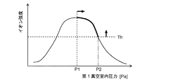
- the figure which shows the range of the pressure in a 1st intermediate
- FIG. 1 is a schematic configuration diagram centering on the ion path of the mass spectrometer of the present embodiment. Note that, as a matter of course, since FIG. 1 is a schematic configuration diagram, the size of each component in the figure, the distance between different components, the distance, and the like do not necessarily reflect the actual device.
- the mass spectrometer mass-separates an ionization chamber 2 inside a chamber 1 for ionizing a component (compound) in a liquid sample under a substantially atmospheric pressure atmosphere and ions derived from the sample component.
- a first intermediate vacuum chamber 3 and a second intermediate chamber 3 which have an analysis chamber 5 that is maintained in a high vacuum atmosphere for detection, and the degree of vacuum gradually increases between the ionization chamber 2 and the analysis chamber 5. It has a vacuum chamber 4.
- the first intermediate vacuum chamber 3 is connected to a rotary pump (RP) 18 via a pipe 6 such as a polyvinyl chloride (PVC) hose having a length of about 1 m, and is evacuated by the rotary pump 18.
- RP rotary pump
- the second intermediate vacuum chamber 4 and the analysis chamber 5 are directly connected to the first port 7 and the second port 8 of the turbo molecular pump (TMP) 19, respectively, and the rotary pump 18 and the turbo molecular pump (TMP) 19 are connected. Both are evacuated. That is, this mass spectrometer has a multi-stage differential evacuation system configuration, so that the inside of the analysis chamber 5, which is the final stage, is maintained at a high degree of vacuum.
- an electrospray ionization (ESI) probe 10 that ionizes the components in the sample by electrostatically spraying the sample is arranged.
- the ionization chamber 2 and the first intermediate vacuum chamber 3 communicate with each other through a desolvation pipe 11 which is a capillary pipe that is heated to an appropriate temperature.
- a desolvation pipe 11 which is a capillary pipe that is heated to an appropriate temperature.
- the Q-array type ion guide 12 that transports ions while converging them by the action of a high frequency electric field.
- the Q array type ion guide 12 has a configuration in which four virtual rod-shaped electrodes are arranged so as to surround the ion optical axis C, and one virtual rod-shaped electrode extends the ion optical axis C. It consists of a plurality of electrodes divided in the direction. Further, in the Q array type ion guide 12, the space surrounded by the virtual rod-shaped electrode is gradually narrowed in the ion advancing direction.
- the first intermediate vacuum chamber 3 and the second intermediate vacuum chamber 4 communicate with each other through a minute ion passage hole (orifice) 13a formed on the top of the skimmer 13 having a substantially conical shape.
- a quadrupole ion guide 14 is arranged to transport ions while converging them by the action of a high frequency electric field.
- the quadrupole ion guide 14 is composed of four rod electrodes arranged so as to surround the ion optical axis and are parallel to the ion optical axis.
- the second intermediate vacuum chamber 4 and the analysis chamber 5 are communicated with each other through a minute ion passage hole 15a formed in the plate-shaped aperture electrode 15.
- a quadrupole mass filter 16 as a mass separator and an ion detector 17 are arranged in the analysis room 5.
- the quadrupole mass filter 16 has a configuration in which four rod electrodes extending parallel to the ion optical axis C are arranged around the ion optical axis C.
- a prefilter composed of four rod electrodes shorter than the rod electrodes forming the quadrupole mass filter 16 is arranged.
- the ion detector 17 is composed of, for example, a conversion dynode and a secondary electron multiplier.
- the Q array type ion guide 12, the skimmer 13, the quadrupole type ion guide 14, the aperture electrode 15, the quadrupole mass filter 16 and the ion detector 17 which are arranged along the ion optical axis C.
- a DC voltage or a voltage obtained by adding a high frequency voltage and a DC voltage is applied to each of the power supplies (not shown).
- a predetermined DC voltage is also applied to the ESI probe 10.
- a general analysis operation in the mass spectrometer of the present embodiment will be briefly described.
- a liquid sample eluted from an LC column (not shown) is introduced into the ESI probe 10
- a charge is applied to the liquid sample at the tip of the probe 10 and is sprayed into the ionization chamber 2 as minute charged droplets.
- the charged droplets come into contact with the surrounding air to be atomized and the solvent in the droplets evaporates.
- the sample components in the liquid droplets are ejected with an electric charge, and ions derived from the sample components are generated.
- Ions that have entered the first intermediate vacuum chamber 3 along with the gas flow are appropriately cooled by coming into contact with the residual gas, and progress while being captured by the high frequency electric field formed by the Q array type ion guide 12.
- the ions are converged near the ion passage hole 13a at the top of the skimmer 13 and sent to the second intermediate vacuum chamber 4 through the ion passage hole 13a.
- the ions that have entered the second intermediate vacuum chamber 4 are captured by the high-frequency electric field formed by the quadrupole ion guide 14 and travel while being converged near the ion optical axis C. Then, the ions are sent to the analysis chamber 5 through the ion passage holes 15 a formed in the aperture electrode 15.
- the ions are introduced into the quadrupole mass filter 16 through the prefilter.
- the pre-filter corrects the disturbance of the electric field formed in the vicinity of the front edge of the rod electrode of the quadrupole mass filter 16, whereby ions are smoothly and efficiently introduced into the quadrupole mass filter 16. ..
- a voltage obtained by superposing a high frequency voltage on a DC voltage is applied to each rod electrode of the quadrupole mass filter 16, and only ions having a specific mass-to-charge ratio corresponding to the voltage are applied to the quadrupole mass filter 16. It passes through and reaches the ion detector 17.
- the ion detector 17 generates an ion intensity signal having a magnitude corresponding to the amount of ions that have arrived, and sends this signal to a data processing unit (not shown).
- the mass-to-charge ratio of ions that can pass through the quadrupole mass filter 16 changes.
- a mass-to-charge ratio scan over a predetermined mass-to-charge ratio range can be performed, and a mass spectrum (profile spectrum) showing a change in the ion intensity signal over the mass-to-charge ratio range can be obtained.
- the mass spectrometer of the present embodiment is smaller than the conventional general quadrupole mass spectrometer, and various measures have been taken to realize the miniaturization while ensuring sufficient performance.
- the ions to be measured which are derived from the sample components generated in the ionization chamber 2, finally reach the ion detector 17 from the desolvation tube 11 via each component. Therefore, in order to downsize the device, a linear space between the opening in the desolvation tube 11 facing the ionization chamber 2 (that is, the ion inlet opening) and the ion incident surface of the ion detector 17 is used. It is necessary to make the length of a certain ion path L1 as short as possible. For that purpose, it is necessary to shorten the length of the Q array type ion guide 12, the quadrupole type ion guide 14, and the quadrupole mass filter 16.
- the length of the rod electrode of the quadrupole mass filter 16 is 200 mm or more, while the Q array type ion guide which is an ion guide located upstream thereof.
- the length of 12 and the quadrupole ion guide 14 is 100 mm or less, which is relatively short originally. Therefore, even if the lengths of the Q array type ion guide 12 and the quadrupole type ion guide 14 are further shortened, the effect on downsizing of the device is small, and the device sensitivity may be unacceptable.
- the length of each component forming the ion path L1 is made as short as possible, and in particular, the quadrupole mass filter whose ratio to the length of the ion path L1 is relatively large.
- the length L2 of the 16 rod electrodes is significantly shorter than that of a general quadrupole mass spectrometer.
- the length L2 of the rod electrode of the quadrupole mass filter 16 is 200 mm or more in the conventional general quadrupole mass spectrometer, but when the length L1 of the ion path is 400 mm or less.
- the length L2 of the rod electrode is 150 mm or less, more preferably 120 mm or less. In the mass spectrometer of this embodiment, the length L2 of the rod electrode is 100 mm.
- the ions introduced into the quadrupole mass filter 16 progress while oscillating in the radial direction by the action of the high-frequency electric field while passing through the space surrounded by the four rod electrodes, but the mass separation performance depends on the number of oscillations. To do.
- the mass separation performance deteriorates.
- the voltage applied to the rod electrodes specifically, the DC bias voltage commonly applied to the four rod electrodes forming the quadrupole mass filter 16 is properly adjusted.
- the number of vibrations of the ions is kept to the same level as that of the conventional apparatus, and sufficient mass separation performance is maintained.
- the cross-sectional opening shape of the desolvation tube 11 is circular, and its inner diameter d is constant and 0.4 mm ⁇ regardless of the position in the ion passage direction. That is, the inner diameter d of the first opening in the present invention is 0.4 mm ⁇ and the opening area is 0.126 mm 2 . This is larger than the inner diameter of the atmospheric pressure orifice in the conventional small-sized mass spectrometer disclosed in Patent Documents 1 and 2.
- the ions derived from the sample component generated in the ionization chamber 2 are not converged by the high frequency electric field and taken into the desolvation pipe 11, but taken into the desolvation pipe 11 by the gas flow formed by the pressure difference as described above. Be done.
- the flow rate of the gas flowing from the desolvation pipe 11 is proportional to the fourth power of the radius of the opening when the desolvation pipe 11 has a circular opening. Therefore, a slight difference in inner diameter appears as a large difference in gas flow rate. For example, when the inner diameter of the opening of the desolvation pipe 11 is 0.4 mm ⁇ , the gas flow rate is about three times as large as when the inner diameter is 0.3 mm ⁇ . An increase in gas flow rate leads to an increase in ion introduction amount.
- the inner diameter (that is, the inner diameter of the first opening) d of the desolvation tube 11 or the opening area thereof affects the efficiency of introducing ions from the ionization chamber 2 to the first intermediate vacuum chamber 3 and increases the amount of introduced ions.
- the larger the inner diameter d the better. Further, the larger the inner diameter d, the less likely the sample droplets are clogged, and the higher the maintainability.
- the gas inflow amount from the ionization chamber 2 to the first intermediate vacuum chamber 3 is also increased. Therefore, in order to make the pressure in the first intermediate vacuum chamber 3 the same as when the inner diameter d is small, It is necessary to enhance the capacity of the rotary pump 18.
- FIG. 2 is a graph showing actual measurement results of changes in ionic strength when the pressure in the first intermediate vacuum chamber is changed.
- the relationship between the pressure and the ionic strength has a convex peak shape at any inner diameter d, but the larger the inner diameter d, the lower the pressure range in which the peak of ionic strength appears (that is, the higher the degree of vacuum is. ) Understand. That is, the optimum pressure is higher when the inner diameter of the desolvation pipe 11 is smaller than when it is larger. From this result, by setting the pressure so that the inner diameter of the first opening, that is, the product of the opening area and the pressure in the first intermediate vacuum chamber falls within a predetermined range, the inner diameter of the first opening is changed. It can be concluded that a sufficient ionic strength can be obtained.
- the pressure in the first intermediate vacuum chamber 3 should be set within the range of 155 Pa to 290 Pa. It is possible to obtain an ionic strength at a level of (here, an intensity of 60% or more of the peak intensity). In this case, the opening area ⁇ pressure is in the range of 19.5 to 36.4 mm 2 ⁇ Pa.
- a desired level of ionic strength can be obtained by setting the pressure in the first intermediate vacuum chamber 3 within the range of 235 Pa to 455 Pa.
- the opening area ⁇ pressure is in the range of 16.6-32.1 mm 2 ⁇ Pa.
- an ionic strength at a level of about half or more of the peak intensity is obtained, so even if it is desired to make the opening area larger than the opening area of the first opening used in the conventional small mass spectrometer,
- the product of the opening area and the pressure in the first intermediate vacuum chamber may be set within the range of about 15 to 40 mm 2 ⁇ Pa.
- the pressure in the first intermediate vacuum chamber 3 changes, The ionic strength may change. Therefore, it is desirable to set the product of the opening area of the first opening and the pressure in the first intermediate vacuum chamber 3 so that the change in ionic strength when the pressure changes is small. According to the results of FIG. 2, when the inner diameter d of the desolvation tube 11 is 0.4 mm ⁇ , the pressure in the first intermediate vacuum chamber 3 is within the pressure range around 215 Pa at which the ionic strength shows a maximum, for example, 175 to 265 Pa.
- the product of the opening area of the first opening and the pressure in the first intermediate vacuum chamber 3 may be set within the range of 20 to 35 mm 2 ⁇ Pa.
- the opening area ⁇ pressure is within the above range of 30 mm 2
- a rotary pump having the ability to maintain the pressure in the first intermediate vacuum chamber 3 at 239 Pa is required.
- the capacity of the rotary pump actually required depends on the internal volume of the first intermediate vacuum chamber 3, but in the mass spectrometer of the present embodiment, the ion path is short as described above, and the conventional general mass spectrometer is used.
- the above pressure can be realized by using a relatively small rotary pump having an exhaust speed of about 12 m 3 /Hr.
- a conventional general mass spectrometer requires a rotary pump having an evacuation speed of about 25 to 30 m 3 /Hr.
- the rotary pump 18 whose pumping speed is about half or less may be used, so the rotary pump 18 can be made quite small.
- the allowable level of the ion intensity is set to 50% or 60% of the peak intensity
- the range of the pressure in the first intermediate vacuum chamber 3 that can realize this is considerably wide, but the rotary pump 18 is as small as possible. From the viewpoint of using a material, it is advisable to keep the pressure within a range higher than P1 and lower than P2 shown in FIG. This makes it possible to suppress the exhaust speed of the rotary pump 18 to a lower level even if the ionic strength is at the same level, which is advantageous for downsizing the rotary pump 18.
- the virtual rod-shaped electrode forming the Q array type ion guide 12 is tapered so that it approaches the optical axis C of the ion as the ions proceed.
- the radius of the substantially circular ion outlet region at the rearmost end of the Q array type ion guide 12 is 2.0 mm ⁇ or less.
- the inner diameter of the circular ion passage hole 13a formed in the skimmer 13 is 0.8 mm ⁇ (opening area: 0.5 mm 2 ) and is 1.0 mm ⁇ (opening area: 0.79 mm 2 ) or less. It has a small diameter.
- the ions trapped by the high frequency electric field can be focused on a small area on the ion optical axis C, thereby reducing the inner diameter of the ion passage hole 13a. Also, ions can be efficiently passed through the ion passage hole 13a. Further, since the inner diameter of the ion passage hole 13a is small, that is, the opening area is small, the amount of gas flowing from the first intermediate vacuum chamber 3 to the second intermediate vacuum chamber 4 can be reduced, and the second intermediate vacuum chamber can be reduced. It is possible to reduce the load on the turbo molecular pump 19 that evacuates the vacuum chamber 4 and the analysis chamber 5.
- the ion guide arranged in the first intermediate vacuum chamber 3 is not limited to the Q array type ion guide, but may be a multipole type RF ion guide which is similarly tapered.
- an ion funnel type ion guide in which a large number of disk-shaped electrodes having circular openings in the center are arranged along the ion optical axis C at narrow intervals and the central opening area of each electrode gradually decreases toward the outlet may be used. ..
- an ion funnel type ion guide in which a large number of disk-shaped electrodes having circular openings in the center are arranged along the ion optical axis C at narrow intervals and the central opening area of each electrode gradually decreases toward the outlet may be used. ..
- the distance between adjacent electrodes is very close to about 1 mm, there is a high possibility that neutral particles or ions will collide with the electrodes.
- the mass spectrometer of the present embodiment since the area of the opening of the desolvation tube 11 corresponding to the first opening of the present invention is larger than that of the conventional small mass spectrometer, the risk of clogging of the first opening is reduced. However, there is a relatively high possibility that the ion guide located on the downstream side will be contaminated. Regarding such a risk, it can be said that, for the above-mentioned reason, it is more preferable to employ the Q array type ion guide or the multipole type RF ion guide having high durability against contamination as the ion guide of the first intermediate vacuum chamber.
- the inner diameter of the ion passage hole 15a formed in the aperture electrode 15 is as small as 1.0 mm ⁇ (opening area: 0.79 mm 2 ).
- the quadrupole ion guide 14 has a higher ion focusing effect than a multipole ion guide having a larger number of poles, such as an octopole ion guide.
- the ions captured by the high-frequency electric field can be focused on a small area on the ion optical axis C, so that the ions can efficiently pass through the ion passage hole 15a even if the inner diameter of the ion passage hole 15a is reduced.
- the inner diameter of the ion passage hole 15a is small, that is, the opening area is small, the amount of gas flowing from the second intermediate vacuum chamber 4 into the analysis chamber 5 can be reduced.
- the load on the vacuum pump (turbo molecular pump 19) that evacuates the analysis chamber 5 can be reduced, and the pressure in the analysis chamber 5 in which the quadrupole mass filter 16 is arranged can be further reduced.
- the ion transmittance and mass resolution of the quadrupole mass filter 16 can be improved.
- the exhaust speed of the turbo molecular pump 19 can be suppressed to 100 L/sec or less by reducing the opening areas of the two ion passage holes 13a and 15a as described above.
- the exhaust speed of the turbo molecular pump is about 200 to 300 L/sec.
- the exhaust speed of the turbo molecular pump can be reduced to about half or less, so a small turbo molecular pump can be used, and when the turbo molecular pump is integrated with the main body of the device.
- the device can be stored compactly.
- the rotary pump 18 is connected to the first intermediate vacuum chamber 3 via the pipe 6 having a length of about 1 m. Therefore, when the mass spectrometer main body is installed on the laboratory bench, the rotary pump 18 can be housed in a space under the laboratory bench, for example, and the size of the rotary pump does not matter to the user. There are many.
- the turbo molecular pump is directly connected to the vacuum chamber forming the analysis chamber, it is substantially integrated with the main body of the mass spectrometer and installed on the bench. This becomes a factor of increasing the volume of the device body.
- the mass spectrometer of the present embodiment it is possible to reduce the size of the device including the rotary pump 18 and the turbo molecular pump 19 while maintaining high detection sensitivity and good maintenance.
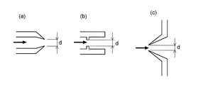
- the desolvation tube 11 had a constant inner diameter in the axial direction, but the desolvation tube 11 has an ion introduction opening for introducing ions from the ionization chamber 2 to the first intermediate vacuum chamber 3.
- the first opening in the present invention is a part that restricts the amount of ions when introducing ions from the ionization chamber 2 to the first intermediate vacuum chamber 3, so the inner diameter or opening area of the first opening is You can define it like this.
- the inner diameter or the opening area of the most advanced opening is formed. Corresponds to the inner diameter or opening area of the first opening.
- the inner diameter or the opening area of the cross-sectional opening in the narrowed portion is the inner diameter of the first opening. Or, it corresponds to the opening area.
- FIG. 4C when the ionization chamber and the first intermediate vacuum chamber communicate with each other through an orifice provided at the top of the sampling cone (for example, the sampling cone may have two stages). The inner diameter or opening area of the orifice corresponds to the inner diameter or opening area of the first opening.
- the atmospheric pressure ion source uses the ESI method, but an atmospheric pressure ion source using the APCI method, the APPI method or the like may be used.
Landscapes
- Chemical & Material Sciences (AREA)
- Analytical Chemistry (AREA)
- Physics & Mathematics (AREA)
- Engineering & Computer Science (AREA)
- Plasma & Fusion (AREA)
- Other Investigation Or Analysis Of Materials By Electrical Means (AREA)
- Electron Tubes For Measurement (AREA)
Priority Applications (5)
| Application Number | Priority Date | Filing Date | Title |
|---|---|---|---|
| US17/291,824 US11721536B2 (en) | 2018-11-29 | 2018-11-29 | Mass spectrometer |
| CN201880098947.7A CN112912991B (zh) | 2018-11-29 | 2018-11-29 | 质量分析装置 |
| EP18941205.9A EP3889997A4 (de) | 2018-11-29 | 2018-11-29 | Massenspektrometer |
| JP2020557485A JP7047936B2 (ja) | 2018-11-29 | 2018-11-29 | 質量分析装置 |
| PCT/JP2018/044042 WO2020110264A1 (ja) | 2018-11-29 | 2018-11-29 | 質量分析装置 |
Applications Claiming Priority (1)
| Application Number | Priority Date | Filing Date | Title |
|---|---|---|---|
| PCT/JP2018/044042 WO2020110264A1 (ja) | 2018-11-29 | 2018-11-29 | 質量分析装置 |
Publications (1)
| Publication Number | Publication Date |
|---|---|
| WO2020110264A1 true WO2020110264A1 (ja) | 2020-06-04 |
Family
ID=70854196
Family Applications (1)
| Application Number | Title | Priority Date | Filing Date |
|---|---|---|---|
| PCT/JP2018/044042 Ceased WO2020110264A1 (ja) | 2018-11-29 | 2018-11-29 | 質量分析装置 |
Country Status (5)
| Country | Link |
|---|---|
| US (1) | US11721536B2 (de) |
| EP (1) | EP3889997A4 (de) |
| JP (1) | JP7047936B2 (de) |
| CN (1) | CN112912991B (de) |
| WO (1) | WO2020110264A1 (de) |
Cited By (2)
| Publication number | Priority date | Publication date | Assignee | Title |
|---|---|---|---|---|
| JP2022048479A (ja) * | 2020-09-15 | 2022-03-28 | 株式会社島津製作所 | 質量分析装置 |
| JP2023100094A (ja) * | 2022-01-05 | 2023-07-18 | 株式会社島津製作所 | 質量分析装置 |
Families Citing this family (5)
| Publication number | Priority date | Publication date | Assignee | Title |
|---|---|---|---|---|
| GB2541301B (en) | 2012-03-15 | 2017-07-12 | Fisher & Paykel Healthcare Ltd | Respiratory gas humidification system |
| GB2577634B (en) | 2012-04-27 | 2020-09-30 | Fisher & Paykel Healthcare Ltd | Respiratory humidification apparatus |
| GB2583046B8 (en) | 2013-09-13 | 2021-04-28 | Fisher & Paykel Healthcare Ltd | Resilient probe mount for a humidification system |
| US10449319B2 (en) | 2014-02-07 | 2019-10-22 | Fisher & Paykel Healthcare Limited | Respiratory humidification system |
| SG10202106016TA (en) | 2016-12-07 | 2021-07-29 | Fisher and paykel healthcare ltd | Sensing arrangements for medical devices |
Citations (4)
| Publication number | Priority date | Publication date | Assignee | Title |
|---|---|---|---|---|
| JPH0574409A (ja) * | 1991-09-12 | 1993-03-26 | Hitachi Ltd | 質量分析の方法および装置 |
| JP2000067805A (ja) * | 1998-08-24 | 2000-03-03 | Hitachi Ltd | 質量分析装置 |
| US20160093480A1 (en) | 2013-05-31 | 2016-03-31 | Micromass Uk Limited | Compact Mass Spectrometer |
| US20160111266A1 (en) | 2013-05-31 | 2016-04-21 | Micromass Uk Limited | Compact Mass Spectrometer |
Family Cites Families (15)
| Publication number | Priority date | Publication date | Assignee | Title |
|---|---|---|---|---|
| JPH07142025A (ja) * | 1993-11-19 | 1995-06-02 | Shimadzu Corp | イオン質量分析装置 |
| JP4581184B2 (ja) | 2000-06-07 | 2010-11-17 | 株式会社島津製作所 | 質量分析装置 |
| GB0907619D0 (en) * | 2009-05-01 | 2009-06-10 | Shimadzu Res Lab Europe Ltd | Ion analysis apparatus and method of use |
| US8242440B2 (en) * | 2009-05-01 | 2012-08-14 | Thermo Finnigan Llc | Method and apparatus for an ion transfer tube and mass spectrometer system using same |
| JP5234019B2 (ja) | 2010-01-29 | 2013-07-10 | 株式会社島津製作所 | 質量分析装置 |
| CN102971826B (zh) * | 2010-06-24 | 2015-07-22 | 株式会社岛津制作所 | 大气压电离质谱仪 |
| US8309916B2 (en) * | 2010-08-18 | 2012-11-13 | Thermo Finnigan Llc | Ion transfer tube having single or multiple elongate bore segments and mass spectrometer system |
| GB2483314B (en) * | 2010-12-07 | 2013-03-06 | Microsaic Systems Plc | Miniature mass spectrometer system |
| JP5722125B2 (ja) * | 2011-06-03 | 2015-05-20 | 株式会社日立ハイテクノロジーズ | 質量分析装置 |
| JP5673848B2 (ja) * | 2011-10-20 | 2015-02-18 | 株式会社島津製作所 | 質量分析装置 |
| JP6269666B2 (ja) * | 2013-06-17 | 2018-01-31 | 株式会社島津製作所 | イオン輸送装置及び該装置を用いた質量分析装置 |
| JP6202103B2 (ja) * | 2013-12-17 | 2017-09-27 | 株式会社島津製作所 | 質量分析装置及び質量分析方法 |
| JP6295150B2 (ja) * | 2014-07-07 | 2018-03-14 | 株式会社日立ハイテクノロジーズ | 質量分析装置 |
| CN107706082B (zh) * | 2016-08-08 | 2019-11-26 | 株式会社岛津制作所 | 用于质谱仪的限流离子引入接口装置 |
| US10103014B2 (en) * | 2016-09-05 | 2018-10-16 | Agilent Technologies, Inc. | Ion transfer device for mass spectrometry |
-
2018
- 2018-11-29 EP EP18941205.9A patent/EP3889997A4/de active Pending
- 2018-11-29 CN CN201880098947.7A patent/CN112912991B/zh active Active
- 2018-11-29 US US17/291,824 patent/US11721536B2/en active Active
- 2018-11-29 WO PCT/JP2018/044042 patent/WO2020110264A1/ja not_active Ceased
- 2018-11-29 JP JP2020557485A patent/JP7047936B2/ja active Active
Patent Citations (4)
| Publication number | Priority date | Publication date | Assignee | Title |
|---|---|---|---|---|
| JPH0574409A (ja) * | 1991-09-12 | 1993-03-26 | Hitachi Ltd | 質量分析の方法および装置 |
| JP2000067805A (ja) * | 1998-08-24 | 2000-03-03 | Hitachi Ltd | 質量分析装置 |
| US20160093480A1 (en) | 2013-05-31 | 2016-03-31 | Micromass Uk Limited | Compact Mass Spectrometer |
| US20160111266A1 (en) | 2013-05-31 | 2016-04-21 | Micromass Uk Limited | Compact Mass Spectrometer |
Non-Patent Citations (2)
| Title |
|---|
| NIHON WATERS K. K, ACQUITY QDA MASS DETECTOR, 8 August 2018 (2018-08-08), Retrieved from the Internet <URL:http://www.waters.com/waters/ja_JP/ACQUITY-QDa-Mass-Detector-for-Chromatographic-Analysis/nav.htm?1ocale=ja_JP&cid=134761404>> |
| See also references of EP3889997A4 |
Cited By (5)
| Publication number | Priority date | Publication date | Assignee | Title |
|---|---|---|---|---|
| JP2022048479A (ja) * | 2020-09-15 | 2022-03-28 | 株式会社島津製作所 | 質量分析装置 |
| JP7396237B2 (ja) | 2020-09-15 | 2023-12-12 | 株式会社島津製作所 | 質量分析装置 |
| JP2023100094A (ja) * | 2022-01-05 | 2023-07-18 | 株式会社島津製作所 | 質量分析装置 |
| JP7729210B2 (ja) | 2022-01-05 | 2025-08-26 | 株式会社島津製作所 | 質量分析装置 |
| US12482645B2 (en) | 2022-01-05 | 2025-11-25 | Shimadzu Corporation | Mass spectrometer |
Also Published As
| Publication number | Publication date |
|---|---|
| US20210391164A1 (en) | 2021-12-16 |
| EP3889997A4 (de) | 2022-04-20 |
| JP7047936B2 (ja) | 2022-04-05 |
| EP3889997A1 (de) | 2021-10-06 |
| CN112912991A (zh) | 2021-06-04 |
| CN112912991B (zh) | 2025-01-24 |
| JPWO2020110264A1 (ja) | 2021-09-27 |
| US11721536B2 (en) | 2023-08-08 |
Similar Documents
| Publication | Publication Date | Title |
|---|---|---|
| JP7047936B2 (ja) | 質量分析装置 | |
| US6803565B2 (en) | Ionization source utilizing a multi-capillary inlet and method of operation | |
| CN110637352B (zh) | 从电子电离源的离子传输 | |
| CN102971826B (zh) | 大气压电离质谱仪 | |
| US6583408B2 (en) | Ionization source utilizing a jet disturber in combination with an ion funnel and method of operation | |
| JP5234019B2 (ja) | 質量分析装置 | |
| US8324565B2 (en) | Ion funnel for mass spectrometry | |
| US11270877B2 (en) | Multipole ion guide | |
| US9177775B2 (en) | Mass spectrometer | |
| CN110277299A (zh) | 电感耦合等离子体质谱分析的串联碰撞/反应池 | |
| KR102746344B1 (ko) | 견고한 이온공급원 | |
| JP2016009562A (ja) | イオン輸送装置及び質量分析装置 | |
| JP4193734B2 (ja) | 質量分析装置 | |
| WO2017013609A1 (zh) | 一种用于质谱仪离子化以及离子引入装置 | |
| US10410849B2 (en) | Multipole ion guide | |
| US20160233069A1 (en) | Gas diffuser ion inlet | |
| CN103650101A (zh) | 三重四极型质量分析装置 | |
| WO2020121252A1 (en) | Mass spectrometer components including programmable elements and devices and systems using them | |
| JP2024506256A (ja) | 質量分析計の真空チャンバにおける圧力制御 | |
| WO2020054013A1 (ja) | 質量分析装置 | |
| US6518581B1 (en) | Apparatus for control of gas flow into a mass spectrometer using a series of small orifices | |
| JP4811361B2 (ja) | 大気圧化学イオン化質量分析装置 | |
| CN113178380A (zh) | 一种大气压电离质谱仪 |
Legal Events
| Date | Code | Title | Description |
|---|---|---|---|
| 121 | Ep: the epo has been informed by wipo that ep was designated in this application |
Ref document number: 18941205 Country of ref document: EP Kind code of ref document: A1 |
|
| ENP | Entry into the national phase |
Ref document number: 2020557485 Country of ref document: JP Kind code of ref document: A |
|
| NENP | Non-entry into the national phase |
Ref country code: DE |
|
| ENP | Entry into the national phase |
Ref document number: 2018941205 Country of ref document: EP Effective date: 20210629 |
|
| WWG | Wipo information: grant in national office |
Ref document number: 201880098947.7 Country of ref document: CN |