WO2020110331A1 - Contenant d'évacuation - Google Patents
Contenant d'évacuation Download PDFInfo
- Publication number
- WO2020110331A1 WO2020110331A1 PCT/JP2019/008460 JP2019008460W WO2020110331A1 WO 2020110331 A1 WO2020110331 A1 WO 2020110331A1 JP 2019008460 W JP2019008460 W JP 2019008460W WO 2020110331 A1 WO2020110331 A1 WO 2020110331A1
- Authority
- WO
- WIPO (PCT)
- Prior art keywords
- opening
- tubular portion
- discharge
- ejection head
- porous
- Prior art date
- Legal status (The legal status is an assumption and is not a legal conclusion. Google has not performed a legal analysis and makes no representation as to the accuracy of the status listed.)
- Ceased
Links
Images


Classifications
-
- A—HUMAN NECESSITIES
- A47—FURNITURE; DOMESTIC ARTICLES OR APPLIANCES; COFFEE MILLS; SPICE MILLS; SUCTION CLEANERS IN GENERAL
- A47K—SANITARY EQUIPMENT; ACCESSORIES THEREFOR, e.g. TOILET ACCESSORIES
- A47K5/00—Holders or dispensers for soap, toothpaste or the like
- A47K5/14—Foam or lather making devices
-
- A—HUMAN NECESSITIES
- A45—HAND OR TRAVELLING ARTICLES
- A45D—HAIRDRESSING OR SHAVING EQUIPMENT; EQUIPMENT FOR COSMETICS OR COSMETIC TREATMENTS, e.g. FOR MANICURING OR PEDICURING
- A45D27/00—Shaving accessories
- A45D27/02—Lathering the body; Producing lather
-
- A—HUMAN NECESSITIES
- A45—HAND OR TRAVELLING ARTICLES
- A45D—HAIRDRESSING OR SHAVING EQUIPMENT; EQUIPMENT FOR COSMETICS OR COSMETIC TREATMENTS, e.g. FOR MANICURING OR PEDICURING
- A45D34/00—Containers or accessories specially adapted for handling liquid toiletry or cosmetic substances, e.g. perfumes
-
- B—PERFORMING OPERATIONS; TRANSPORTING
- B05—SPRAYING OR ATOMISING IN GENERAL; APPLYING FLUENT MATERIALS TO SURFACES, IN GENERAL
- B05B—SPRAYING APPARATUS; ATOMISING APPARATUS; NOZZLES
- B05B7/00—Spraying apparatus for discharge of liquids or other fluent materials from two or more sources, e.g. of liquid and air, of powder and gas
- B05B7/0018—Spraying apparatus for discharge of liquids or other fluent materials from two or more sources, e.g. of liquid and air, of powder and gas with devices for making foam
- B05B7/0025—Spraying apparatus for discharge of liquids or other fluent materials from two or more sources, e.g. of liquid and air, of powder and gas with devices for making foam with a compressed gas supply
- B05B7/0031—Spraying apparatus for discharge of liquids or other fluent materials from two or more sources, e.g. of liquid and air, of powder and gas with devices for making foam with a compressed gas supply with disturbing means promoting mixing, e.g. balls, crowns
- B05B7/0037—Spraying apparatus for discharge of liquids or other fluent materials from two or more sources, e.g. of liquid and air, of powder and gas with devices for making foam with a compressed gas supply with disturbing means promoting mixing, e.g. balls, crowns including sieves, porous members or the like
-
- B—PERFORMING OPERATIONS; TRANSPORTING
- B65—CONVEYING; PACKING; STORING; HANDLING THIN OR FILAMENTARY MATERIAL
- B65D—CONTAINERS FOR STORAGE OR TRANSPORT OF ARTICLES OR MATERIALS, e.g. BAGS, BARRELS, BOTTLES, BOXES, CANS, CARTONS, CRATES, DRUMS, JARS, TANKS, HOPPERS, FORWARDING CONTAINERS; ACCESSORIES, CLOSURES, OR FITTINGS THEREFOR; PACKAGING ELEMENTS; PACKAGES
- B65D47/00—Closures with filling and discharging, or with discharging, devices
- B65D47/04—Closures with discharging devices other than pumps
- B65D47/06—Closures with discharging devices other than pumps with pouring spouts or tubes; with discharge nozzles or passages
-
- B—PERFORMING OPERATIONS; TRANSPORTING
- B05—SPRAYING OR ATOMISING IN GENERAL; APPLYING FLUENT MATERIALS TO SURFACES, IN GENERAL
- B05B—SPRAYING APPARATUS; ATOMISING APPARATUS; NOZZLES
- B05B11/00—Single-unit hand-held apparatus in which flow of contents is produced by the muscular force of the operator at the moment of use
- B05B11/01—Single-unit hand-held apparatus in which flow of contents is produced by the muscular force of the operator at the moment of use characterised by the means producing the flow
- B05B11/10—Pump arrangements for transferring the contents from the container to a pump chamber by a sucking effect and forcing the contents out through the dispensing nozzle
- B05B11/1087—Combination of liquid and air pumps
Definitions
- the present invention relates to a discharge container.
- discharge containers that discharge liquid such as body wash as bubbles have been widely used.
- the liquid contained in the discharge container is mixed with a gas such as air to generate bubbles, and the bubbles thus generated are discharged from the discharge port formed in the discharge head of the discharge container. It is supposed to be done.
- Patent Document 1 discloses a technique of attaching an attachment to a discharge head and devising the shape of the attachment to improve the appearance of bubbles discharged from a discharge container.
- Patent Document 1 cannot sufficiently secure the shape retention of the foam, and there is room for improvement in improving the appearance of the foam.
- the present invention relates to effectively improving the appearance of bubbles discharged by a discharge container.
- an aspect of the present invention is a discharge container including a discharge head having a discharge port through which bubbles are discharged, and a discharge head attachment attached to the discharge head, wherein the discharge head attachment Includes a tubular portion connected to the discharge port on one side and having a first opening on the other side, and a porous portion provided on one side of the tubular portion. , The second opening is formed, and the peripheral portion of the first opening is at least partially extended along the circumferential direction of the tubular portion.
- the appearance of bubbles discharged from the discharge container can be effectively improved.
- FIG. 3 is a perspective view showing the ejection head attachment according to the same embodiment. It is a side surface partial sectional view showing the attachment for ejection heads concerning the embodiment. It is a figure which partially shows the porous part provided in the attachment for ejection heads which concerns on the same embodiment. It is a figure which shows typically the foam formed using the attachment for ejection heads which concerns on the same embodiment.
- FIG. 6 is a perspective view showing an ejection head attachment according to another embodiment different from the ejection head attachment shown in FIGS. 2 and 3. It is a side surface partial sectional view showing the attachment for ejection heads concerning the embodiment.
- the embodiment of the present invention relates to a discharge container.
- the discharge container 1 according to the embodiment of the present invention is a discharge container that generates bubbles by mixing a liquid with air and discharges the bubbles from the discharge port of the discharge head.
- the discharge container 1 which is a pump-type discharge container that discharges bubbles from the discharge port of the discharge nozzle by operating the pump mechanism in conjunction with the discharge nozzle being pushed down will be described.
- the discharge container may be one that discharges bubbles from the discharge port of the discharge nozzle, and may be, for example, a squeeze-type discharge container that discharges bubbles from the discharge port of the discharge nozzle by squeezing the container body. Good.
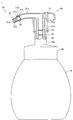
- FIG. 1 is a partial side sectional view showing the discharge container 1.
- the direction from the container body 10 to the dispenser 20 to be described later is referred to as an upward direction for easy understanding.
- the discharge container 1 can assume various postures when used by the user, the direction from the container body 10 to the dispenser 20 does not necessarily mean the vertically upward direction.
- the discharge container 1 includes a discharge head 21 having a discharge port 21d through which bubbles are discharged, and a discharge head attachment 30 attached to the discharge head 21.
- the ejection container 1 includes a container body 10 in which a liquid is stored, a dispenser 20 including an ejection head 21, and an ejection head attachment 30.
- the container body 10 is a hollow member having a mouth at the upper end, and the dispenser 20 is attached to the mouth.
- the liquid forming the foam discharged by the discharge container 1 is contained inside the container body 10.
- Various liquids are applied as the liquid stored in the container body 10, and are not particularly limited, but for example, liquid wash such as body wash, hand wash, face wash, hair cosmetics (for example, A hair styling agent, a fixing agent, a hair-growth agent and the like), skin cosmetics (for example, lotion, milky lotion or beauty essence), shaving foam, dishwashing detergent and the like are applied.
- the viscosity of the liquid is also not particularly limited, but at 25° C., for example, preferably 1 mPa ⁇ s or more, more preferably 2 mPa ⁇ s or more, even more preferably 1000 mPa ⁇ s or less, and 500 mPa ⁇ s. -S or less is more preferable, and 100 mPa-s or less is even more preferable.
- the viscosity of the liquid can be measured using, for example, a B-type viscometer.
- a measurement condition for measuring the viscosity a rotor type, a rotation speed, and a rotation time determined based on the viscosity level in each viscometer can be appropriately selected.
- the container body 10 is made of resin, for example.
- the dispenser 20 discharges the liquid contained in the container body 10 as bubbles.
- the dispenser 20 is made of resin, for example.
- the dispenser 20 includes a discharge head 21 and a cap 22.
- the dispenser 20 is attached to the container body 10 by screwing the cap 22 into the mouth of the container body 10.
- the dispenser 20 includes a pump mechanism (not shown) that generates bubbles by mixing the liquid contained in the container body 10 with air and sends the bubbles to the ejection head 21.
- the pump mechanism includes a liquid piston that can slide vertically in the liquid cylinder, an air piston that can slide vertically in the air cylinder, and a pump mechanism that is arranged inside the mouth of the container body 10. It has a stem that can move in the vertical direction in conjunction with the liquid piston and the air piston, and a spring that urges the stem upward.
- a mixing chamber 29 in which the liquid supplied from the liquid piston and the air supplied from the air cylinder are mixed is formed below the discharge head 21.
- the ejection head 21 is pushed down, the liquid piston and the air piston are pushed down together with the stem, the liquid contained in the container body 10 is supplied to the mixing chamber 29 from the liquid piston, and the mixing chamber 29 is supplied from the air cylinder. Is supplied with air. Thereby, in the mixing chamber 29, the liquid is mixed with the air to generate bubbles.
- the ejection head 21 includes a first cylindrical portion 21a that extends through the inside of a tubular portion 22a protruding upward from the radial center side of the cap 22 and extends in the vertical direction, and an outer peripheral portion of the tubular portion 22a of the cap 22. And a nozzle portion 21c extending from the upper portion of the first cylindrical portion 21a in the radial direction of the first cylindrical portion 21a.
- the internal flow passage of the first cylindrical portion 21a communicates with the internal flow passage of the nozzle portion 21c, and a discharge port 21d is formed at the tip of the nozzle portion 21c.
- the above-mentioned mixing chamber 29 is formed in the lower portion of the internal flow passage of the first cylindrical portion 21a, and the mixing chamber 29 in the internal flow passage of the first cylindrical portion 21a is downstream (that is, upper side) in order from the bottom.
- a first porous body 23 and a second porous body 24 are provided. Therefore, after the bubbles formed in the mixing chamber 29 become finer by passing through the first porous body 23 and the second porous body 24, they pass through the internal flow passage of the first cylindrical portion 21a and the inside of the nozzle portion 21c. Sent to the flow path. Thereafter, the bubbles are discharged from the discharge port 21d at the tip of the nozzle portion 21c.
- the ejection head attachment 30 is attached to the ejection port 21 d of the ejection head 21. Therefore, the bubbles generated by the dispenser 20 pass through the ejection head 21 and are sent from the ejection port 21d to the ejection head attachment 30, and pass through the ejection head attachment 30 and are ejected to the outside of the ejection container 1.
- the ejection head attachment 30 is a member for improving the appearance of bubbles ejected from the ejection container 1.
- the foam generated by the dispenser 20 passes through the inside of the discharge head attachment 30 and flows out of the discharge container 1, so that the foam having a desired shape according to the shape of the discharge head attachment 30 is generated. It becomes possible to discharge.
- the discharge head attachment 30 since the discharge head attachment 30 is provided with the porous portion as described later, the shape retention of bubbles can be improved. Therefore, the appearance of bubbles discharged from the discharge container 1 can be effectively improved.
- the ejection head attachment 30 will be described in detail later.
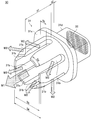
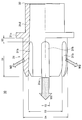
- FIGS. 2 and 3 are a perspective view and a side partial sectional view showing the attachment 30 for the ejection head, respectively.
- the ejection head attachment 30 includes a tubular portion 31 that is connected to the ejection port 21d of the ejection head 21 on one side and has a first opening 31a on the other side, and a tubular portion. 31 and a porous portion 32 provided on one side of 31. Further, a second opening 31b is formed on a side portion of the tubular portion 31, and a peripheral edge portion of the first opening 31a extends at least partially along the circumferential direction of the tubular portion 31. ..
- the ejection head attachment 30 is formed of a resin such as polyethylene, polypropylene, polyethylene terephthalate, or ABS resin.
- the ejection head attachment 30 is manufactured by, for example, injection molding, and in this case, the tubular portion 31 and the porous portion 32 are integrally formed.
- the tubular portion 31 is a tubular portion having openings at both ends, and specifically has a substantially cylindrical shape.
- a flange portion 31c protruding outward in the circumferential direction of the tubular portion 31 is formed in the tubular portion 31 on the center side in the axial direction of the tubular portion 31.
- the fitting portion 31d corresponding to a portion of the tubular portion 31 on one side (that is, the side opposite to the first opening 31a side) with respect to the flange portion 31c is provided from the ejection port 21d of the ejection head 21 to the inner periphery of the nozzle portion 21c. It is inserted and fitted in the section. Therefore, the cross-sectional shape of the fitting portion 31d is a shape corresponding to the cross-sectional shape of the nozzle portion 21c.
- the ejection head attachment 30 is positioned with respect to the ejection head 21 by the flange portion 31c hitting the tip of the nozzle portion 21c. In this way, the ejection head attachment 30 can be connected to the ejection port 21d of the ejection head 21 on one side.
- the ejection head attachment 30 is connected to the ejection port 21d of the ejection head 21 such that the axial direction of the tubular portion 31 is laterally or obliquely downward. That is, it is preferable that the flow path of the ejection head attachment 30b faces sideways or obliquely downward.
- a second opening 31b is formed on a side portion of the tubular portion 31 on the other side (that is, the first opening 31a side) with respect to the flange portion 31c.
- the plurality of second openings 31b are formed at intervals in the circumferential direction of the tubular portion 31, and each second opening 31b is continuous with the first opening 31a and extends in the axial direction of the tubular portion 31. Is formed to extend. Therefore, as shown in FIGS. 2 and 3, the peripheral portion of the first opening 31a extends along the circumferential direction of the tubular portion 31 between the adjacent second openings 31b.
- FIG. 2 shows an example in which the six second openings 31b are arranged at equal intervals in the circumferential direction of the tubular portion 31.
- the porous portion 32 is a film-shaped portion having a plurality of through holes formed therein, and is provided on one side of the tubular portion 31 (that is, on the opposite side of the first opening 31a side). Specifically, the porous portion 32 is provided at the one end of the tubular portion 31.
- the bubbles sent from the ejection head 21 to the ejection head attachment 30 become finer by passing through the porous portion 32. In this way, the porous portion 32 has a function of reducing the bubble diameter, which is the diameter of the bubbles discharged from the discharge container 1.
- FIG. 4 is a diagram partially showing the porous portion 32.
- the porous portion 32 has a mesh shape as shown in FIG. Specifically, the porous portion 32 has a plurality of thread-shaped portions 32a spaced apart from each other and extending in the first direction, and a plurality of thread-shaped portions 32b spaced apart from each other and extending in a second direction orthogonal to the first direction. And the plurality of thread portions 32a and the plurality of thread portions 32b define a plurality of substantially rectangular hole portions 32c.
- the plurality of thread-shaped portions 32a and the plurality of thread-shaped portions 32b are arranged at equal intervals, and the distance between the adjacent thread-shaped portions 32a and the distance between the adjacent thread-shaped portions 32b are substantially equal to each other. There is. Therefore, each hole 32c has a substantially square shape with the same size.
- the opening L1 [ ⁇ m] of the porous portion 32 corresponds to the length of one side of the hole 32c (that is, the distance between the adjacent thread-like portions). Further, the wire diameter D1 [ ⁇ m] of the thread-like portion in the porous portion 32 is substantially the same between the thread-like portions, and the opening ratio R1 [%] is represented by the following formula (1).
- the bubbles sent from the discharge head 21 to the discharge head attachment 30 pass through the porous portion 32, so that the bubble diameter of the bubbles can be reduced.
- the present inventor has found through the results of the test described below that the shape retention of the foam can be improved by reducing the diameter of the foam discharged from the discharge container 1. .. Further, the present inventor has obtained, through the results of the above-described test, knowledge regarding the size of the porous portion 32 that is preferable from the viewpoint of more effectively improving the shape retention of the foam discharged from the discharge container 1.
- the opening L1 of the porous portion 32 is defined as the size of the foam sent from the discharge head 21 to the discharge head attachment 30. It has been found that it is preferable that it is smaller than the average bubble diameter.
- the opening ratio R1 of the porous portion 32 is preferably larger than 10%.
- the opening ratio R1 of the porous portion 32 is the same as the opening ratio of the porous body (specifically, the first porous body 23 and the second porous body 24) provided in the internal flow path of the ejection head 21. Or, it is preferably smaller than the opening ratio of the porous body.
- nylon, polyester or the like can be used as the material of the porous portion 32.
- the second opening 31b is formed on the side portion of the tubular portion 31 of the ejection head attachment 30 mounted on the ejection head 21 of the ejection container 1.
- the peripheral portion of the first opening 31 a extends at least partially along the circumferential direction of the tubular portion 31.
- the flow of bubbles discharged from the first opening 31a is shown by an arrow M1
- the flow of bubbles discharged from each second opening 31b is shown by an arrow M2.
- the flow of bubbles passing through the first opening 31a indicated by the arrow M1 and the flow of bubbles passing through each second opening 31b indicated by the arrow M2 are formed, so that a bubble having a desired shape is formed. It becomes possible to discharge.
- the ratio S3/S1 of the inner diameter S3 of the tubular portion 31 to the axial length S1 of the tubular portion 31 in the second opening 31b is preferably 0.3 or more, and 0.5 or more. It is more preferable that it is, and it is preferably 3.5 or less, and more preferably 3.0 or less. This is because by setting the ratio S3/S1 to a value within an appropriate range that is not excessively small and is not excessively large, the flow of bubbles through each of the second openings 31b is appropriately formed, and the discharge head Since the edge portion (for example, the edge portion 9a of the foam body 9 in FIG.
- the shape of the first opening 31a is other than circular, as the value of the inner diameter S3 of the tubular portion 31, for example, the diameter of a circle having the same area as the opening area of the first opening 31a may be used. it can.
- the axial length S1 of the tubular portion 31 in the second opening 31b is preferably longer than the length S6 of the peripheral portion of the first opening 31a extending between the adjacent second openings 31b. Further, the axial length S1 of the tubular portion 31 in the second opening 31b is preferably longer than the circumferential length S5 of the tubular portion 31 in the second opening 31b.
- FIG. 5 is a diagram schematically showing the foam body 9 formed by using the ejection head attachment 30.
- the foam body 9 is a molded article of foam formed on the foam receiver by discharging the foam from the discharge container 1 to the foam receiver (for example, the palm of the hand) which is the object to receive the foam.
- the foam body 9 formed by using the ejection head attachment 30 has six edge portions 9a formed radially from the central portion toward the outside. These edge portions 9a are formed in the foam body 9 by forming a flow of bubbles through the respective second openings 31b of the ejection head attachment 30 when ejecting bubbles from the ejection container 1.
- the above-described ejection head attachment 30 it is possible to obtain a desired shape of the foam body 9.
- the circumferential length S5 is preferably 1 mm or more, more preferably 1.2 mm or more, preferably 2 mm or less, and more preferably 1.8 mm or less. This is because it becomes easy to obtain a desired shape as the shape of the bubble to be discharged by setting the length S5 above a certain level, and when the length S5 is excessively long, the flange portion 31c of the tubular portion 31 is formed. On the other hand, the strength on the side of the first opening 31a is reduced.
- the axial length S1 is preferably 4 mm or more, more preferably 5 mm or more, preferably 8 mm or less, and more preferably 7 mm or less. This is because it becomes easier to obtain a desired shape as the shape of the bubble to be discharged by setting the length S1 to a certain level or more, and when the length S1 is excessively long, the flange portion 31c of the tubular portion 31 is formed. On the other hand, the strength on the side of the first opening 31a is reduced.
- the axial interval S2 of the tubular portion 31 between the second opening 31b and the flange portion 31c is 0.5 mm or more. It is preferably 1 mm or more, and more preferably 1 mm or more. This is because it is possible to suppress the bubbles passing through the second opening 31b from coming into contact with the flange portion 31c by setting the interval S2 to a certain degree or more, so that the edge portion 9a formed on the foam body 9 is desired. This is because it is possible to prevent the shape from becoming thicker.
- the outer diameter S4 of the tubular portion 31 on the first opening 31a side with respect to the flange portion 31c is preferably 5 mm or more, and 7 mm or more. It is more preferable that the thickness is 15 mm or less, more preferably 10 mm or less. This is because it is easy to obtain a desired shape as the shape of the bubble to be ejected, by making the outer diameter S4 not too small and within a suitable range not too large.
- the inner diameter S3 of the tubular portion 31 is preferably 4 mm or more, more preferably 5 mm or more, and 13 mm or less. Is preferable and 10 mm or less is more preferable. This is because it becomes easy to obtain a desired shape as the shape of the bubble to be discharged, by making the inside diameter S3 not excessively small and within a proper range not excessively large.
- the porous portion 32 is provided on one side of the tubular portion 31 of the attachment 30 for the discharge head.
- the bubbles sent from the ejection head 21 to the ejection head attachment 30 can be ejected to the outside of the ejection container 1 after passing through the porous portion 32. Therefore, the bubble diameter of the bubbles discharged from the discharge container 1 can be reduced. Thereby, the shape retention of the foam discharged from the discharge container 1 can be improved. Therefore, the appearance of bubbles discharged from the discharge container 1 can be effectively improved.
- the pressure of the bubbles sent from the ejection head 21 to the ejection head attachment 30 increases when passing through the porous portion 32. Therefore, since the porous portion 32 is provided in the ejection head attachment 30, the ejection is performed toward the radially outer side of the tubular portion 31 through the second opening 31b, as compared with the case where the porous portion 32 is not provided. The force of the flow of bubbles can be increased. Thereby, it is possible to more easily obtain a desired shape of the foam discharged from the discharge container 1.
- the ejection head attachment 30 is described as the ejection head attachment mounted on the ejection head 21 of the ejection container 1.
- the shape of the ejection head attachment mounted on the ejection head 21 is the same as the shape described above. It is not particularly limited.
- the ejection head attachment 130 is different from the above-described ejection head attachment 30 mainly in the shape and number of the second openings formed in the tubular portion.
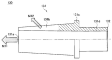
- 6 and 7 are a perspective view and a side partial cross-sectional view showing the ejection head attachment 130, respectively.
- the ejection head attachment 130 includes a tubular portion 131 and a porous portion 132. Similar to the ejection head attachment 30 described above, the tubular portion 131 is connected to the ejection port 21d of the ejection head 21 on one side and has the first opening 131a on the other side.
- the porous portion 132 is a film-shaped portion in which a plurality of through holes are formed, and is provided on one side of the tubular portion 131 (that is, on the side opposite to the first opening 131a side).
- the ejection head attachment 130 is manufactured by, for example, injection molding.
- a flange portion 131c protruding outward in the circumferential direction of the tubular portion 131 is formed on the axial center side of the tubular portion 131 in the tubular portion 131.
- the fitting portion 131d on one side (that is, the side opposite to the first opening 131a side) of the flange portion 131c of the tubular portion 131 is inserted from the discharge port 21d of the discharge head 21 into the inner peripheral portion of the nozzle portion 21c.
- the ejection head attachment 130 is positioned with respect to the ejection head 21 by being fitted and the flange portion 131c abutting against the tip of the nozzle portion 21c.
- one substantially V-shaped second opening 131b is connected to the first opening 131a on the other side of the flange 131c of the tubular portion 131 (that is, on the side of the first opening 131a).
- the width of the cylindrical portion 131 in the second opening 131b in the circumferential direction becomes smaller as it goes to one side (that is, the side opposite to the first opening 131a side).
- the peripheral portion of the first opening 131a extends along the circumferential direction of the tubular portion 131 except for the portion connected to the second opening 131b.
- the porous portion 132 is provided on one side of the second opening 131b of the tubular portion 131 (that is, on the opposite side of the first opening 131a side).
- the second opening 131b is formed in the side portion of the tubular portion 131, similarly to the ejection head attachment 30 described above. Further, the peripheral portion of the first opening 131 a extends at least partially along the circumferential direction of the tubular portion 131. Thereby, the bubbles sent from the ejection head 21 to the ejection head attachment 130 are ejected in the axial direction of the tubular portion 131 from the first opening 131a, and pass through the second opening 131b to the radially outer side of the tubular portion 131. Can be discharged toward.
- the flow of bubbles discharged from the first opening 131a is shown by an arrow M11
- the flow of bubbles discharged from the second opening 131b is shown by an arrow M12.
- the flow of bubbles passing through the first opening 131a indicated by the arrow M11 and the flow of bubbles passing through the second opening 131b indicated by the arrow M12 are formed, thereby ejecting bubbles having a desired shape. It becomes possible to do.
- the porous portion 132 is provided on one side of the tubular portion 131, similarly to the ejection head attachment 30 described above.
- the bubbles sent from the ejection head 21 to the ejection head attachment 130 can be ejected to the outside of the ejection container 1 after passing through the porous portion 132. Therefore, the bubble diameter of the bubbles discharged from the discharge container 1 can be reduced. Thereby, the shape retention of the foam discharged from the discharge container 1 can be improved. Therefore, the appearance of bubbles discharged from the discharge container 1 can be effectively improved.
- the shape of the ejection head attachment mounted on the ejection head 21 of the ejection container 1 is not particularly limited.
- the shape of the portion on the other side (that is, the side of the first opening 31a) with respect to the flange portion 31c in the ejection head attachment 30 is a substantially cylindrical shape
- FIG. 7 the shape of the portion on the other side (that is, the first opening 131a side) of the flange portion 131c of the ejection head attachment 130 is a substantially rounded rectangular tube shape.
- the inner diameters of the tubular portions 31, 131 are smaller than those of the porous portions 32, 132.
- the opening portions 31a, 131a become smaller toward the porous portions 32, 132.
- bubbles are discharged using the discharge container 1 including the above-described discharge head attachment 30 under conditions in which the dimensions of the porous portion 32 are variously changed, and thus the average bubble diameter at the time of discharge for each condition. Also, the shape retention of the discharged foam was evaluated. The average bubble diameter at the time of ejection is the average value of the bubble diameters of the bubbles after passing through the porous portion 32 of the ejection head attachment 30. Further, in this test, the pressing force, which is an index showing the degree of the force of pressing down the ejection head 21, was evaluated under each condition.
- bubbles were discharged from the discharge container 1 into the glass cylinder, and the average bubble diameter at the time when about 1 second elapsed from the time when the bubbles were discharged was measured by using a bubble diameter measuring device. It was measured.
- a bubble diameter measuring device a device that obtains various kinds of information such as the bubble diameter by roughly performing image processing on the image showing the captured bubble was used.
- the maximum stress when the ejection head 21 was pushed down to the bottom dead center at a speed of about 30 mm/s was measured as a pushing force by using a stress measuring machine.
- a stress measuring device a device for measuring the stress generated in the ejection head 21 by detecting the force applied to the ejection head 21 using a load cell was used.
- the wire diameter was 50 ⁇ m, the opening ratio was 37%, and the thickness was 83 ⁇ m.
- the opening ratio R1 of the porous portion 32 is preferably the same as the opening ratio of the porous body (37% in this test) or smaller than the opening ratio of the porous body.
- Tables 1 to 3 show the results when liquids having viscosities of 8.5 mPa ⁇ s, 5.8 mPa ⁇ s and 2.0 mPa ⁇ s were used as the liquid contained in the container body 10, respectively.
- the evaluation result of the shape retention of the foam is represented by each symbol of “ ⁇ ”, “ ⁇ ”, “ ⁇ ” and “ ⁇ ”, and “ ⁇ ”, “ ⁇ ”, “ ⁇ ”, “ ⁇ ”, “ ⁇ indicates that the shape retention of the bubbles becomes higher (that is, becomes better).
- the average bubble diameter of the bubbles sent from the ejection head 21 to the ejection head attachment 30 was investigated. Specifically, the average bubble diameter at the time of ejection was measured in a state where the ejection head attachment in which the porous portion 32 was omitted from the configuration of the ejection head attachment 30 was attached to the ejection head 21. As a result, the average bubble diameter of the bubbles sent from the ejection head 21 to the ejection head attachment 30 is such that the viscosity of the liquid contained in the container body 10 is 8.5 mPa ⁇ s, 5.8 mPa ⁇ s, 2.0 mPa ⁇ s. It was found that the values are approximately 105 ⁇ m, approximately 125 ⁇ m, and approximately 153 ⁇ m, respectively.
- the opening L1 of the porous portion 32 causes the average bubble diameter of the bubbles sent from the ejection head 21 to the ejection head attachment 30 (approximately). It can be seen that the shape retention is further improved under the conditions 2 to 4 in which the opening L1 is smaller than the average bubble diameter as compared with the condition 1 larger than 105 ⁇ m). Further, referring to Table 1, as compared with the condition 5 in which the opening ratio R1 of the porous portion 32 is smaller than 10% although the opening L1 is smaller than the average bubble diameter, the opening ratio R1 of the porous portion 32 is 10%. Under the larger conditions 2 to 4, the shape retention is further improved.
- the opening L1 of the porous portion 32 is the average bubble diameter of bubbles sent from the ejection head 21 to the ejection head attachment 30. It can be seen that the shape retention is further improved under the conditions 7 to 9 in which the opening L1 is smaller than the average bubble diameter as compared with the condition 6 larger than (approximately 125 ⁇ m). Further, referring to Table 2, as compared with the condition 10 in which the opening ratio R1 of the porous portion 32 is smaller than 10% even though the opening L1 is smaller than the average bubble diameter, the opening ratio R1 of the porous portion 32 is 10%. It can be seen that the shape retention is further improved under the larger conditions 7 to 9.
- the average opening diameter L1 of the porous portion 32 is the average bubble diameter of the bubbles sent from the ejection head 21 to the ejection head attachment 30. It can be seen that the shape retention property is further improved under the conditions 12 to 14 in which the opening L1 is smaller than the average bubble diameter as compared with the condition 11 larger than (approximately 153 ⁇ m). Furthermore, referring to Table 3, as compared with the condition 15 in which the opening ratio R1 of the porous portion 32 is smaller than 10% even though the opening L1 is smaller than the average bubble diameter, the opening ratio R1 of the porous portion 32 is 10%. It can be seen that the shape retention is further improved under the larger conditions 12 to 14.
- the shape retention of the foam discharged by the discharge container 1 is further improved by making the opening L1 of the porous portion 32 smaller than the average bubble diameter of the bubbles sent from the discharge head 21 to the discharge head attachment 30. It turns out that it can be improved effectively.
- the opening L1 is equal to or larger than the average bubble diameter of the bubbles sent to the ejection head attachment 30, the coarse bubbles contained in the bubbles sent to the ejection head attachment 30 can be reduced. Therefore, even if the average bubble diameter does not change significantly before and after passing through the porous portion 32, the shape retention of the bubbles can be improved.
- the shape retention of the foam discharged from the discharge container 1 can be more effectively improved by making the opening ratio R1 of the porous portion 32 larger than 10%.
- the opening ratio R1 since the pressure applied to the bubbles passing through the porous portion 32 increases as the opening ratio R1 decreases, it is conceivable that the bubbles are likely to break or coalesce after passing through the porous portion 32. Therefore, by setting the opening ratio R1 to be larger than 10%, it is possible to suppress the occurrence of bubble breakage and coalescence, and it is possible to suppress the generation of coarse pores. It is thought that it can be effectively improved.
- the opening ratio R1 is set such that the pressing force becomes small enough to improve the operability of the discharge container 1.
- the shape retention of the foam was evaluated by the same method as above.
- the evaluation result of the shape retention of the foam discharged from the above-mentioned discharge container in which the porous portion 32 was not provided in the discharge head attachment was “x”. Therefore, it was confirmed that the shape retention of the foam can be improved by providing the porous portion 32 in the attachment for the ejection head.
- the second openings 31b and 131b formed in the side portions of the tubular portion 131 of the ejection head attachments 30 and 130 are formed to be continuous with the first openings 31a and 131a has been described.
- the second opening according to the present invention does not have to be continuous with the first opening. That is, the second opening does not have to extend to the peripheral portion of the first opening and be connected to the peripheral portion.
- the shape and number of the second openings in the ejection head attachment according to the present invention are not particularly limited, and may be different from the ejection head attachments 30 and 130 described above.
- a portion between the second openings 31b adjacent to each other in the ejection head attachment 30 (that is, a portion projecting from the flange portion 31c to the first opening 31a side) has a rounded shape (for example, a spherical shape). You may have.
- a rounded shape for example, a spherical shape
- the ejection head attachments 30 and 130 may be manufactured by another processing method.
- the tubular portions 31, 131 and the porous portions 32, 132 may be formed as separate members.
- the tubular portions 31 and 131 may be composed of a plurality of members, and the porous portions 32 and 132 may be composed of a plurality of members.
- the first opening 31a, 131a side portion and the porous portions 32, 132 side portion may be formed as separate members.
- the ejection head attachments 30, 130 may be configured by two members, a member on the side of the first openings 31a, 131a and a member on the side of the porous portions 32, 132.
- the ejection head attachments 30, 130 may be further provided with a cover for covering the first openings 31a, 131a.
- a cover for covering the first openings 31a, 131a.
- the example in which the two porous bodies (specifically, the first porous body 23 and the second porous body 24) are provided in the dispenser 20 has been described, but it is provided in the dispenser 20.
- the number of porous bodies is not particularly limited to the above example, and three porous bodies may be provided in the dispenser 20, for example.
- the present invention further discloses the following attachments for a discharge container and a discharge head.
- a discharge container comprising a discharge head having a discharge port for discharging bubbles and a discharge head attachment attached to the discharge head, wherein the discharge head attachment is connected to the discharge port on one side.
- a tubular portion having a first opening on the other side and a porous portion provided on the one side of the tubular portion, and a second opening is formed on the side portion of the tubular portion. The peripheral portion of the first opening extends at least partially along the circumferential direction of the tubular portion.
- ⁇ 2> The discharge container according to ⁇ 1>, wherein the aperture of the porous portion is smaller than the average bubble diameter of the bubbles sent from the discharge head to the discharge head attachment.
- ⁇ 3> The discharge container according to ⁇ 1> or ⁇ 2>, wherein the opening ratio of the porous portion is greater than 10%.
- ⁇ 4> The discharge according to any one of ⁇ 1> to ⁇ 3>, wherein the inner diameter of the tubular portion is smaller on the first opening side than the porous portion as it approaches the porous portion.
- container. ⁇ 5> A container body in which a liquid is stored, and a dispenser including the ejection head are provided, and the dispenser generates bubbles by mixing the liquid stored in the container body with air.
- the discharge container according to any one of ⁇ 1> to ⁇ 4> which includes a pump mechanism that sends bubbles to the discharge head.
- the discharge container according to ⁇ 5> further including a liquid contained in the container body.
- the viscosity of the liquid contained in the container body at 25° C. is preferably 1 mPa ⁇ s or more, more preferably 2 mPa ⁇ s or more, 1000 mPa ⁇ s or less, and 500 mPa ⁇ s or less.
- the discharge container according to ⁇ 5> or ⁇ 6> wherein 100 mPa ⁇ s or less is more preferable.
- ⁇ 8> The discharge container according to any one of ⁇ 1> to ⁇ 7>, wherein a porous body is provided in an internal flow path of the discharge head.
- ⁇ 9> The discharge container according to ⁇ 8>, wherein a plurality of the porous bodies are provided.
- ⁇ 10> The discharge container according to ⁇ 8> or ⁇ 9>, wherein the opening ratio of the porous portion is the same as the opening ratio of the porous body or smaller than the opening ratio of the porous body.
- a flange portion is formed on a central side in the axial direction of the tubular portion so as to project outward in the circumferential direction of the tubular portion. Discharge container described.
- ⁇ 12> The discharge container according to any one of ⁇ 1> to ⁇ 11>, wherein the plurality of second openings are formed at intervals in the circumferential direction of the tubular portion.
- ⁇ 13> The discharge container according to ⁇ 12>, wherein the peripheral portion of the first opening extends along the circumferential direction of the tubular portion between the adjacent second openings.
- ⁇ 14> The length of the tubular portion in the second opening in the axial direction is longer than the length of the peripheral edge portion of the first opening extending between the adjacent second openings.
- ⁇ 15> The discharge container according to any one of ⁇ 1> to ⁇ 14>, wherein the second opening is continuous with the first opening and extends in the axial direction of the tubular portion.
- the ratio of the inner diameter of the tubular portion to the axial length of the tubular portion in the second opening is preferably 0.3 or more, more preferably 0.5 or more, Further, the discharge container according to any one of the above items ⁇ 1> to ⁇ 15>, which is preferably 3.5 or less, and more preferably 3.0 or less.
- ⁇ 18> The discharge container according to any one of ⁇ 1> to ⁇ 17>, wherein a circumferential width of the tubular portion at the second opening is reduced toward the one side.
- ⁇ 19> The discharge container according to any one of ⁇ 1> to ⁇ 18>, wherein the porous portion has a mesh shape.
- the tubular portion is connected to the ejection port such that an axial direction of the tubular portion faces sideways or obliquely downward. Discharge container described.
- An attachment for an ejection head which is attached to an ejection head having an ejection port through which foam is ejected, which has a cylindrical portion that can be connected to the ejection port on one side and has a first opening on the other side.
- a porous portion provided on the one side of the tubular portion, a second opening is formed in a side portion of the tubular portion, and a peripheral portion of the first opening is at least partially formed.
- An ejection head attachment which extends along the circumferential direction of the tubular portion.
- ⁇ 22> The attachment for an ejection head according to ⁇ 21>, wherein the opening of the porous portion is smaller than the average bubble diameter of the bubbles sent from the ejection head to the attachment for the ejection head.
- ⁇ 23> The ejection head attachment according to ⁇ 21> or ⁇ 22>, wherein the opening ratio of the porous portion is larger than 10%.
- ⁇ 24> The discharge according to any one of ⁇ 21> to ⁇ 23>, wherein the inner diameter of the tubular portion is smaller on the first opening side than the porous portion as it approaches the porous portion. Attachment for head.
- a flange portion is formed on an axial center side of the tubular portion, the flange portion projecting outward in the circumferential direction of the tubular portion. Attachment for the ejection head described.
- ⁇ 26> The attachment for a discharge head according to any one of ⁇ 21> to ⁇ 25>, wherein the plurality of second openings are formed at intervals in the circumferential direction of the tubular portion.
- ⁇ 27> The ejection head attachment according to ⁇ 26>, wherein the peripheral edge portion of the first opening extends along the circumferential direction of the tubular portion between the adjacent second openings.
- the second opening is formed so as to extend in the axial direction of the tubular portion so as to be continuous with the first opening. attachment.
- the ratio of the inner diameter of the tubular portion to the axial length of the tubular portion in the second opening is preferably 0.3 or more, more preferably 0.5 or more, Further, the ejection head attachment according to any one of ⁇ 21> to ⁇ 29>, which is preferably 3.5 or less, and more preferably 3.0 or less.
- ⁇ 32> The ejection head attachment according to any one of ⁇ 21> to ⁇ 31>, in which a circumferential width of the tubular portion in the second opening is reduced toward the one side. .. ⁇ 33>
- Discharge container 9 Foam 9a Edge part 10
- Container body 20 Dispenser 21
- Discharge head 21a 1st cylinder part 21b 2nd cylinder part 21c
- Nozzle part 21d Discharge port 22
- Cap 22a Tubular part 23 1st porous body 24
- 2nd porous body 29
- Mixing Chamber 30,130 Ejection head attachment 31,131 Cylindrical portion 31a,131a First opening 31b,131b Second opening 31c,131c Flange portion 31d,131d Fitting portion 32,132 Porous portion 32a,32b Thread portion 32c Hole portion
Landscapes
- Engineering & Computer Science (AREA)
- Mechanical Engineering (AREA)
- Health & Medical Sciences (AREA)
- Public Health (AREA)
- Closures For Containers (AREA)
- Containers And Packaging Bodies Having A Special Means To Remove Contents (AREA)
Abstract
Priority Applications (4)
| Application Number | Priority Date | Filing Date | Title |
|---|---|---|---|
| EP19888695.4A EP3889065B1 (fr) | 2018-11-29 | 2019-03-04 | Contenant d'évacuation |
| CN201980074176.2A CN112996732A (zh) | 2018-11-29 | 2019-03-04 | 喷出容器 |
| JP2020557537A JP7264914B2 (ja) | 2018-11-29 | 2019-03-04 | 吐出容器 |
| US17/295,550 US20220008943A1 (en) | 2018-11-29 | 2019-03-04 | Discharge container |
Applications Claiming Priority (2)
| Application Number | Priority Date | Filing Date | Title |
|---|---|---|---|
| JP2018223743 | 2018-11-29 | ||
| JP2018-223743 | 2018-11-29 |
Publications (1)
| Publication Number | Publication Date |
|---|---|
| WO2020110331A1 true WO2020110331A1 (fr) | 2020-06-04 |
Family
ID=70851943
Family Applications (1)
| Application Number | Title | Priority Date | Filing Date |
|---|---|---|---|
| PCT/JP2019/008460 Ceased WO2020110331A1 (fr) | 2018-11-29 | 2019-03-04 | Contenant d'évacuation |
Country Status (6)
| Country | Link |
|---|---|
| US (1) | US20220008943A1 (fr) |
| EP (1) | EP3889065B1 (fr) |
| JP (1) | JP7264914B2 (fr) |
| CN (1) | CN112996732A (fr) |
| TW (1) | TWI832844B (fr) |
| WO (1) | WO2020110331A1 (fr) |
Families Citing this family (3)
| Publication number | Priority date | Publication date | Assignee | Title |
|---|---|---|---|---|
| IT202300006747A1 (it) * | 2023-04-06 | 2024-10-06 | Rieke Packaging Systems Ltd | Componente a rete modulare per erogatori di schiuma e utensili e metodi per la fabbricazione degli stessi |
| WO2025123279A1 (fr) | 2023-12-14 | 2025-06-19 | The Procter & Gamble Company | Distributeur à pompe de mousse et son ensemble pompe à mousse |
| CN221931863U (zh) * | 2023-12-19 | 2024-11-01 | 深圳市益时尚科技有限公司 | 洗手液装置 |
Citations (11)
| Publication number | Priority date | Publication date | Assignee | Title |
|---|---|---|---|---|
| JPH0177866U (fr) * | 1987-11-06 | 1989-05-25 | ||
| JP2003253297A (ja) * | 2002-02-28 | 2003-09-10 | Lion Corp | 洗浄剤及び洗浄剤製品 |
| JP2008259932A (ja) * | 2007-04-10 | 2008-10-30 | Kao Corp | 泡吐出器 |
| JP3163646U (ja) * | 2010-01-22 | 2010-10-28 | ユニプラス株式会社 | 泡噴出器における噴出装置 |
| JP2014201316A (ja) * | 2013-04-01 | 2014-10-27 | 大和製罐株式会社 | ポンプ容器 |
| JP1520288S (fr) * | 2014-04-10 | 2015-03-30 | ||
| KR20160098115A (ko) * | 2016-07-28 | 2016-08-18 | 주식회사 아폴로산업 | 포밍펌프 디스펜서용 푸시헤드 |
| JP2017214147A (ja) * | 2016-05-30 | 2017-12-07 | 株式会社ダイゾー | 発泡性内容物の吐出部材およびエアゾール製品 |
| JP2017213486A (ja) * | 2016-05-30 | 2017-12-07 | 株式会社丸一 | エアゾール容器用吐出具 |
| WO2018062236A1 (fr) * | 2016-09-29 | 2018-04-05 | 花王株式会社 | Récipient de distribution de mousse |
| JP2018052610A (ja) | 2016-09-30 | 2018-04-05 | 株式会社吉野工業所 | 吐出器用アタッチメント及び吐出器 |
Family Cites Families (8)
| Publication number | Priority date | Publication date | Assignee | Title |
|---|---|---|---|---|
| US2612293A (en) * | 1949-01-21 | 1952-09-30 | Michel Daniel | Container closure member having a dispensing valve therein |
| JP2589642Y2 (ja) * | 1993-06-25 | 1999-02-03 | 釜屋化学工業株式会社 | 泡噴出容器 |
| JP4489568B2 (ja) * | 2004-11-30 | 2010-06-23 | 株式会社吉野工業所 | フォーマーディスペンサー |
| WO2009038452A1 (fr) * | 2007-09-17 | 2009-03-26 | Rexam Airspray N.V. | Us088574 ensemble distributeur de mousse |
| JP6228364B2 (ja) * | 2013-01-31 | 2017-11-08 | 日本クロージャー株式会社 | 泡出しキャップ |
| GB2510400A (en) * | 2013-02-01 | 2014-08-06 | Cambridge Consultants | Foam Dispenser |
| JP6359289B2 (ja) | 2014-02-28 | 2018-07-18 | 花王株式会社 | 泡吐出容器 |
| KR101514811B1 (ko) * | 2014-06-02 | 2015-04-23 | 주식회사 아폴로산업 | 압착용기용 거품발생기 |
-
2019
- 2019-03-04 EP EP19888695.4A patent/EP3889065B1/fr active Active
- 2019-03-04 US US17/295,550 patent/US20220008943A1/en not_active Abandoned
- 2019-03-04 CN CN201980074176.2A patent/CN112996732A/zh active Pending
- 2019-03-04 WO PCT/JP2019/008460 patent/WO2020110331A1/fr not_active Ceased
- 2019-03-04 JP JP2020557537A patent/JP7264914B2/ja active Active
- 2019-03-05 TW TW108107275A patent/TWI832844B/zh active
Patent Citations (11)
| Publication number | Priority date | Publication date | Assignee | Title |
|---|---|---|---|---|
| JPH0177866U (fr) * | 1987-11-06 | 1989-05-25 | ||
| JP2003253297A (ja) * | 2002-02-28 | 2003-09-10 | Lion Corp | 洗浄剤及び洗浄剤製品 |
| JP2008259932A (ja) * | 2007-04-10 | 2008-10-30 | Kao Corp | 泡吐出器 |
| JP3163646U (ja) * | 2010-01-22 | 2010-10-28 | ユニプラス株式会社 | 泡噴出器における噴出装置 |
| JP2014201316A (ja) * | 2013-04-01 | 2014-10-27 | 大和製罐株式会社 | ポンプ容器 |
| JP1520288S (fr) * | 2014-04-10 | 2015-03-30 | ||
| JP2017214147A (ja) * | 2016-05-30 | 2017-12-07 | 株式会社ダイゾー | 発泡性内容物の吐出部材およびエアゾール製品 |
| JP2017213486A (ja) * | 2016-05-30 | 2017-12-07 | 株式会社丸一 | エアゾール容器用吐出具 |
| KR20160098115A (ko) * | 2016-07-28 | 2016-08-18 | 주식회사 아폴로산업 | 포밍펌프 디스펜서용 푸시헤드 |
| WO2018062236A1 (fr) * | 2016-09-29 | 2018-04-05 | 花王株式会社 | Récipient de distribution de mousse |
| JP2018052610A (ja) | 2016-09-30 | 2018-04-05 | 株式会社吉野工業所 | 吐出器用アタッチメント及び吐出器 |
Non-Patent Citations (1)
| Title |
|---|
| See also references of EP3889065A4 |
Also Published As
| Publication number | Publication date |
|---|---|
| TWI832844B (zh) | 2024-02-21 |
| US20220008943A1 (en) | 2022-01-13 |
| JPWO2020110331A1 (ja) | 2021-09-27 |
| EP3889065B1 (fr) | 2026-04-15 |
| JP7264914B2 (ja) | 2023-04-25 |
| EP3889065A4 (fr) | 2022-10-05 |
| CN112996732A (zh) | 2021-06-18 |
| TW202019561A (zh) | 2020-06-01 |
| EP3889065A1 (fr) | 2021-10-06 |
Similar Documents
| Publication | Publication Date | Title |
|---|---|---|
| JP7264914B2 (ja) | 吐出容器 | |
| US8104650B2 (en) | Anti drip device for liquid dispensers | |
| JP6636843B2 (ja) | 泡噴出容器 | |
| JP6535313B2 (ja) | 泡吐出装置 | |
| JP5141880B2 (ja) | 二重容器 | |
| JP7057158B2 (ja) | 泡吐出器 | |
| WO2017179684A1 (fr) | Dispositif de décharge de mousse | |
| TWI608970B (zh) | 內塞和具備該內塞的液體收容容器、以及注口的前端構造和具備該構造的液體收容容器 | |
| EP3444198B1 (fr) | Dispositif de décharge de mousse | |
| CN103079709B (zh) | 包括喷雾头的流体产品分配装置 | |
| JP5617013B1 (ja) | ハンドスプレーガン及び洗浄剤組成物の吐出方法 | |
| JP7189737B2 (ja) | 泡吐出器 | |
| JP7223643B2 (ja) | 泡吐出器 | |
| JP2022523578A (ja) | 摩耗インジケータを有する取出しノズルを含むワイプディスペンサー | |
| US10897986B2 (en) | Brush device that dispenses cleaning fluid | |
| JP6621367B2 (ja) | 泡吐出容器 | |
| JP5781404B2 (ja) | 泡噴出容器 | |
| JP6622246B2 (ja) | 泡吐出装置 | |
| JP5680908B2 (ja) | ノズル付き押出容器 | |
| JP5829009B2 (ja) | 噴霧ノズル | |
| JP5710402B2 (ja) | 泡噴出容器 | |
| JP2025021845A (ja) | 泡吐出容器、装着キャップ及びノズル | |
| JP2017148772A (ja) | 気液混合体噴射装置 | |
| JP2020186005A (ja) | 泡吐出具及び泡吐出容器 | |
| JP2025115860A (ja) | ポンプ式吐出器 |
Legal Events
| Date | Code | Title | Description |
|---|---|---|---|
| 121 | Ep: the epo has been informed by wipo that ep was designated in this application |
Ref document number: 19888695 Country of ref document: EP Kind code of ref document: A1 |
|
| ENP | Entry into the national phase |
Ref document number: 2020557537 Country of ref document: JP Kind code of ref document: A |
|
| WWE | Wipo information: entry into national phase |
Ref document number: 2101003037 Country of ref document: TH |
|
| NENP | Non-entry into the national phase |
Ref country code: DE |
|
| ENP | Entry into the national phase |
Ref document number: 2019888695 Country of ref document: EP Effective date: 20210629 |
|
| WWG | Wipo information: grant in national office |
Ref document number: 2019888695 Country of ref document: EP |