WO2020111024A1 - Récipient à capuchon, procédé d'examen de fuite pour récipient double, récipient de libération de lamination, et son procédé de fabrication - Google Patents
Récipient à capuchon, procédé d'examen de fuite pour récipient double, récipient de libération de lamination, et son procédé de fabrication Download PDFInfo
- Publication number
- WO2020111024A1 WO2020111024A1 PCT/JP2019/046063 JP2019046063W WO2020111024A1 WO 2020111024 A1 WO2020111024 A1 WO 2020111024A1 JP 2019046063 W JP2019046063 W JP 2019046063W WO 2020111024 A1 WO2020111024 A1 WO 2020111024A1
- Authority
- WO
- WIPO (PCT)
- Prior art keywords
- container
- inner bag
- cap
- laminated
- outer shell
- Prior art date
- Legal status (The legal status is an assumption and is not a legal conclusion. Google has not performed a legal analysis and makes no representation as to the accuracy of the status listed.)
- Ceased
Links
Images


Classifications
-
- B—PERFORMING OPERATIONS; TRANSPORTING
- B65—CONVEYING; PACKING; STORING; HANDLING THIN OR FILAMENTARY MATERIAL
- B65D—CONTAINERS FOR STORAGE OR TRANSPORT OF ARTICLES OR MATERIALS, e.g. BAGS, BARRELS, BOTTLES, BOXES, CANS, CARTONS, CRATES, DRUMS, JARS, TANKS, HOPPERS, FORWARDING CONTAINERS; ACCESSORIES, CLOSURES, OR FITTINGS THEREFOR; PACKAGING ELEMENTS; PACKAGES
- B65D1/00—Rigid or semi-rigid containers having bodies formed in one piece, e.g. by casting metallic material, by moulding plastics, by blowing vitreous material, by throwing ceramic material, by moulding pulped fibrous material or by deep-drawing operations performed on sheet material
- B65D1/02—Bottles or similar containers with necks or like restricted apertures, designed for pouring contents
-
- B—PERFORMING OPERATIONS; TRANSPORTING
- B65—CONVEYING; PACKING; STORING; HANDLING THIN OR FILAMENTARY MATERIAL
- B65D—CONTAINERS FOR STORAGE OR TRANSPORT OF ARTICLES OR MATERIALS, e.g. BAGS, BARRELS, BOTTLES, BOXES, CANS, CARTONS, CRATES, DRUMS, JARS, TANKS, HOPPERS, FORWARDING CONTAINERS; ACCESSORIES, CLOSURES, OR FITTINGS THEREFOR; PACKAGING ELEMENTS; PACKAGES
- B65D41/00—Caps, e.g. crown caps or crown seals, i.e. members having parts arranged for engagement with the external periphery of a neck or wall defining a pouring opening or discharge aperture; Protective cap-like covers for closure members, e.g. decorative covers of metal foil or paper
- B65D41/02—Caps or cap-like covers without lines of weakness, tearing strips, tags, or like opening or removal devices
- B65D41/04—Threaded or like caps or cap-like covers secured by rotation
Definitions
- the present invention relates to a container with a cap, a leak inspection method for a double container, a laminated peeling container, and a manufacturing method thereof.
- Patent Literature 1 discloses a cap provided with a riding portion (projection) at the terminal end portion of the thread of the male screw portion as a loosening stopper when the cap is tightened by screwing. With this configuration, it is possible to grasp the end point at the time of tightening by the click feeling when the projection provided on the lower surface of the cap exceeds the riding portion.
- Patent Document 2 air is supplied into the inner bag, and the presence or absence of perforation in the inner bag is inspected based on whether or not the pressure in the inner bag reaches a predetermined value after a lapse of a predetermined time.
- the present invention has been made in view of such circumstances and provides a container with a cap capable of preventing overrun of the cap.
- the present invention has been made in view of such circumstances, and provides a leak inspection method capable of detecting whether or not there is a pinhole in the inner bag of a double container.
- a pinch-off part (seal part) when one end of the laminated parison is welded is provided at the bottom of the laminated peeling container as shown in Patent Document 3, but the inner bag is detached from the bottom at this pinch-off part. There is. If the inner bag is detached from the bottom with the contents remaining in the inner bag, the contraction of the inner bag cannot be regulated, which may block the flow path or lead to pinholes. There is.
- the welding layers in the pinch-off portion are adhered to each other by a plurality of biting portions so as to be engaged with each other.
- the mold structure becomes complicated. , Leading to an increase in production costs. Further, in such a configuration, there is also a problem that the pinch-off portion cannot be provided with an outside air introduction portion for introducing outside air between the outer shell and the inner bag.
- the present invention has been made in view of such circumstances, and provides a laminated peeling container in which the detachment of the inner bag from the bottom is limited.
- a cap-equipped container having a container body and a cap, wherein the cap has a female screw portion, and the container body has a male screw portion that is screwed into the female screw portion at its mouth.
- the cap includes a protrusion at a position closer to the container body than the female screw portion, and the container body engages with the protrusion to restrict a loosening of the cap, and a screw is tightened more than the riding part.
- a container with a cap which is provided on the side of the direction and has a stopper portion for restricting the overrun of the cap.
- the container body is provided with the stopper portion on the screw fastening direction side with respect to the riding portion, it is possible to prevent the overrun of the cap.
- At least one of the height of the stopper portion and the radial width of the stopper portion is made larger than that of the riding portion.
- the protrusions are provided at two locations facing each other in the circumferential direction, and the riding portion and the stopper portion are also provided at two locations facing each other in the circumferential direction.
- the height of the stopper part that regulates the overrun of one protrusion is approximately the maximum height that does not interfere with the other protrusion.
- the stopper portion has a tapered surface on the fastening direction side of the screw in the circumferential direction to prevent interference with the other protrusion.
- the container body has an outer shell and an inner bag and is configured such that the inner bag shrinks as the content decreases.
- an air introducing hole is formed in the outer shell, and the riding portion and the stopper portion are provided at substantially the same position in the circumferential direction as the air introducing hole or at a position facing each other in the circumferential direction.
- a double-container leak inspection method wherein the double-container has an outer shell and an inner bag, and is configured such that the inner bag shrinks as the content decreases.
- the method is provided with the step of determining whether or not there is a pinhole in the inner bag based on data obtained when decompressing the inside of the inner bag.
- Data such as the flow rate of air sucked out from the inside of the inner bag when depressurizing the inner bag and the pressure of depressurization differ depending on whether there are pinholes in the inner bag. Based on this difference, it can be determined whether or not there is a pinhole in the inner bag.
- the method is the method described above, wherein the determination is performed based on a flow rate of air sucked from the inner bag during the depressurization.
- the depressurization is performed in a state where a rod-shaped portion is inserted into the inner bag from the mouth of the double container.
- it is a method of pre-peeling a double container, wherein the double container has an outer shell and an inner bag, and is configured such that the inner bag shrinks as the content decreases.
- the method comprises a step of peeling the inner bag from the outer shell by depressurizing the inside of the inner bag with the rod-shaped portion inserted into the inner bag from the mouth of the double container. is there.
- L/H is 0. .40 or more.
- D1 and the circumscribed circle diameter of the rod-shaped portion are D2 and D2/D1 are 0.30 or more. , Is the way.
- the method described above is the method in which the depressurization is performed through a suction port provided in the rod-shaped portion.
- it is the method described above, wherein the suction port is provided at the tip of the rod-shaped portion.
- a laminated peeling container having an outer shell and an inner bag and in which the inner bag shrinks as the content decreases, a container for containing the content, and a bottom of the container.
- a pinch-off portion formed in, the end portion in the longitudinal direction of the pinch-off portion, an engaging portion for engaging the outer shell and the inner bag, the inner bag, in the engaging portion, A protrusion protruding outward in the longitudinal direction is provided, and the outer shell is provided with a recess that engages with the protrusion in the engaging portion, and the protrusion amount of the protrusion in the longitudinal direction is the bottom portion.
- a laminated peeling container having a length in the longitudinal direction from the center of 0.1 to 0.15 times or more the length in the longitudinal direction.
- the engagement portion is provided at the longitudinal end portion of the pinch-off portion, and the protrusion portion of the inner bag and the recess portion of the outer shell are engaged with each other at the engagement portion, thereby limiting the detachment of the inner bag. It is possible to do.
- the tip of the convex portion projects to a position substantially the same as the edge of the bottom surface of the inner bag in the radial direction, or projects outward from the edge of the bottom surface of the inner bag.
- the pinch-off portion is provided with an outside air introduction hole for introducing outside air into the space between the outer shell and the inner bag.
- a method for producing a laminated peeling container which has an outer shell and an inner bag, and in which the inner bag shrinks as the content decreases, a blow using a cylindrical laminated parison.
- a molding step is provided, and the mold has a compression part near the biting part that molds the pinch-off part of the laminated peeling container, and a compression part that compresses the laminated parison before mold clamping to cause the laminated parison to flow in the container inward direction.
- the compression section includes a first compression area formed at a position near both ends in the longitudinal direction of the bite cut section, and a second compression area formed at a position between the first compression areas.
- a method for manufacturing a laminated peeling container wherein a width of the first compression region during mold clamping is narrower than a width of the second compression region during mold clamping.
- the diameter of the die for extruding the laminated parison is not more than 2/ ⁇ times the inner diameter of the portion forming the bottom of the inner diameter of the mold.
- the width of the first compression region at the time of mold clamping is not more than the wall thickness of the laminated parison, and the width of the second compression region at the time of mold clamping is not more than twice the wall thickness of the laminated parison. is there.
- the second compression region has a width of 5 mm or less when the mold is clamped.
- FIG. 4A is an enlarged plan view of an essential part of the container body 2 of FIG. 1
- FIG. 6B is an enlarged front view of an essential part of the container body 2 of FIG.
- FIG. 9 is an exploded perspective view showing the configuration of the head 103 of FIG. 8.
- FIG. 10 is a cross-sectional view showing a state in which the head 103 of FIG. 9 is brought into contact with the end surface of the mouth 109 of the double container 101.
- FIG. 11 is a cross-sectional view showing a state after the inner bag 114 is decompressed from the state of FIG. 10 to shrink the inner bag 114.
- 7 is a graph showing the relationship between time and flow rate, which is measured during depressurization inside the inner bag 114.
- FIG. 14 is a cross-sectional view showing a state in which the head 103 of FIG. 13 is brought into contact with the end surface of the mouth 109 of the double container 101. It is sectional drawing which shows the state after decompressing the inside of the inner bag 114 from the state of FIG. 14, and making the inner bag 114 shrink.
- FIG. 12 is a cross-sectional view corresponding to FIG. 11 when the inner bag 114 is unevenly peeled.
- FIG. 18A is a perspective view of a laminate peeling container 201 according to an embodiment of the third aspect of the present invention
- FIG. 18B is a perspective view showing a bottom portion 232 of the laminate peeling container 201 of FIG. 18A.
- FIG. 22A is an enlarged view of the bottom portion 232 in the cross-sectional view of FIG. 19, and FIG. 22B is an enlarged view of the bottom portion 232 in the cross-sectional view of FIG.
- FIG. 23A is an enlarged perspective view of the bottom portion of the inner bag as viewed from the outside
- FIG. 23B is an enlarged perspective view of the bottom portion of the outer shell as viewed from the inside.
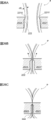
- FIG. 24A is a schematic end view of the blow molding die 202 used in the manufacturing process of the laminated release container 201 of FIG. 18 when cut in a direction perpendicular to the division surface
- FIG. 24B is a division die 202X, It is a schematic diagram of the divided surface of 202Y.
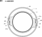
- 25A is a sectional view taken along the line AA in FIGS. 24A and 24B, and
- FIG. 25B is an enlarged view of a region R of FIG. 25A.
- FIGS. 26A to 26C are explanatory views showing a state in which the pair of split molds 202X and 202Y are gradually closed and the laminated parison P is clamped.
- FIG. 27A shows a first modification of the split molds 202X and 202Y shown in FIG. 25B
- FIG. 27B shows a second modification of the split molds 202X and 202Y.
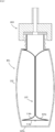
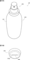
- a laminated peeling container 1 as a container with a cap includes a substantially bottomed cylindrical container body 2 shown in FIGS. 1 to 3, a valve member 3 shown in FIG. And a cap 4 of the formula.
- the container body 2 is provided with a storage portion 5 for storing the content, a mouth portion 6 for discharging the content from the storage portion 5, and a shoulder portion 7.
- the diameter of the mouth portion 6 is smaller than the diameter of the housing portion 5, and the shoulder portion 7 connects the housing portion 5 and the mouth portion 6.
- the container body 2 has a multi-layered structure including an outer shell 12 and an inner bag 14 in the accommodation portion 5, the mouth portion 6 and the shoulder portion 7. 14 contracts away from the shell 12. Further, an air introduction hole 8 is provided only on the outer shell 12 of the side surface of the housing portion 5. A male screw portion 6a is provided on the outer peripheral surface of the mouth portion 6.
- the container body 2 of the present embodiment is provided with a riding portion 21 and a stopper portion 22 at the boundary between the mouth portion 6 and the shoulder portion 7.
- the stopper portion 22 is provided on the screw fastening direction side of the male screw portion 6 a (clockwise direction in FIGS. 1 and 2) with respect to the riding portion 21.
- the riding portion 21 is engaged with a protrusion 44f of the cap 4 which will be described later and restricts looseness of the cap 4. Further, the stopper portion 22 regulates the movement of the protrusion 44f to regulate the overrun of the cap 4.
- a concave portion 23 is formed between the riding portion 21 and the stopper portion 22, and when the cap 4 is screwed into the mouth portion 6, the protrusion 44f is positioned in the concave portion 23.
- a pair of the riding portion 21 and the stopper portion 22 are provided at positions facing each other in the circumferential direction, as shown in FIG.
- the valve member 3 is inserted into the air introduction hole 8 as shown in FIG.
- the valve member 3 is for adjusting the inflow/outflow of air between the space G between the outer shell 12 and the inner bag 14 and the outside.
- the gap between the edge of the air introduction hole 8 and the valve member 3 is opened and closed by the movement of the valve member 3, so that the valve member 3 opens and closes the air introduction hole 8 (Fig. 3)) or a valve that can be opened/closed is provided in the valve member 3 itself, and the air introduction hole 8 can be opened/closed by opening/closing the through hole by the function of this valve.
- valve member 3 is not provided, and a filter is attached to the air introduction hole 8 to adjust the inflow and outflow of air, or the air introduction hole 8 is simply blocked by a finger or the like when the contents are discharged. It can also be configured to perform. In any of the above configurations, the valve member 3 closes the air introduction hole 8 when the outer shell 12 is compressed to make the inner bag 14 compressible, and releases the compressive force to the outer shell 12. Then, the outside air is introduced into the space G.
- the accommodation part 5 is covered with a shrink film after the valve member 3 is attached.
- the valve member mounting recess 5a is formed in the housing portion 5 so that the valve member 3 does not interfere with the shrink film.
- an air circulation groove 5b extending from the valve member mounting recess 5a toward the shoulder 7 is provided so that the valve member mounting recess 5a is not sealed by the shrink film (see FIG. 1).
- valve member mounting recess 5a and the air circulation groove 5b are provided at substantially the same position in the circumferential direction as the pair of riding portions 21 and the stopper portion 22 or at positions facing each other in the circumferential direction. Due to such a positional relationship, in the vicinity of the riding portion 21 and the stopper portion 22, the inner bag 14 and the outer shell 12 are preliminarily separated from the outer shell 12 in the vicinity of the air introduction hole 8 when the valve member 3 is mounted. It becomes difficult to adhere to each other, and the inner bag 14 is easily peeled off when the contents are discharged.
- the valve member mounting recess 5a and the air circulation groove 5b around the air introduction hole 8 are formed. Both of them can be molded at a position deviated from the parting line by 90 degrees. Accordingly, it is possible to prevent an undercut from occurring in the molding of the valve member mounting recess 5a, the air circulation groove 5b, the riding portion 21 and the stopper portion 22.
- the cap 4 includes a cap body 41 and a cap cover 43 connected to the cap body 41 by a hinge 42.
- the cap body 41 includes three members: a main cap member 44, a check valve 45, and a discharge member 46.
- the main cap member 44 is composed of an outer tubular portion 44a, an inner tubular portion 44b, and an annular portion 44c that connects the upper ends thereof.
- a female screw portion 44d that is screwed with the male screw portion 6a of the mouth portion 6 of the container body 2 is formed.
- the end of the outer tubular portion 44a at a position lower than the female screw portion 44d (on the container body 2 side) is an enlarged diameter portion 44e having a larger diameter. ing.
- protrusions 44f protruding inward in the radial direction are formed at two locations facing each other in the circumferential direction (see FIGS. 4A, 4B and 5).
- the protrusion 44f is configured to engage with the riding portion 21 and the stopper portion 22 of the container body 2.
- the relationship between the protrusion 44f and the riding portion 21 and the stopper portion 22 will be described later.
- a valve seat 44g that supports the check valve 45 is formed inside the inner tubular portion 44b.
- the check valve 45 includes a valve body 45a and an elastic piece 45b.
- the check valve 45 is fixed in the inner cylindrical portion 44b of the main cap member 44 by the discharge member 46 engaging with the annular portion 44c of the cap body 41. Then, the check valve 45 is configured such that the valve body 45 a of the check valve 45 is pushed up from the valve seat 44 g of the main cap member 44 when the pressure inside the housing portion 5 (inside the inner bag 14) rises. As a result, by squeezing the container 5 of the container body 2, the contents in the container 5 can be discharged from the discharge port 46a of the discharge member 46.
- the check valve 45 is closed by the urging force of the elastic piece 45b of the check valve 45 that supports the valve body 45a.
- the male screw portion 6a of the mouth portion 6 and the female screw portion 44d of the cap 4 are screwed together, as described above.
- the pair of opposed projections 44f of the cap 4 ride on the corresponding riding portion 21 of the mouth portion 6 and fit into the recess 23, as shown in FIG.
- the surface of the riding portion 21 on the side opposite to the fastening direction is the inclined portion 21a inclined toward the fastening direction side as it goes radially outward, it is possible to easily get over the protrusion 44f. Has become.
- the riding portion 21 functions as a loosening prevention (return prevention), whereby the loosening of the cap 4 can be prevented.
- the mouth portion 6 of the present embodiment has the stopper portion 22 on the screw fastening direction side of the riding portion 21. This makes it possible to prevent the cap 4 from overrunning (overtightening) beyond a predetermined fastening position where the projection 44f and the recess 23 are fitted together.
- the laminated peeling container 1 of the present embodiment can easily grasp the end point of fastening by the click feeling due to the ride of the protrusion 44f, and further, the protrusion 44f and the stopper portion 22 can be separated from each other. The engagement enables the cap 4 to be positioned at an appropriate tightening position.
- the container body 2 since the container body 2 is divided into the outer shell 12 and the inner bag 14, each layer becomes thin and the strength of the stopper portion 22 and the like is limited. Further, in the case of the laminated peeling container 1, it is difficult to locally thicken the inner bag 14 to be peeled by the parison control, because it is necessary to form the inner bag 14 thinly. Therefore, depending on the tightening operation of the cap 4, the stopper portion 22 may be crushed or overrun beyond the stopper portion 22 due to insufficient strength of the stopper portion 22.
- the radial projection width T2 of the stopper portion 22 is set to be larger than the radial projection width T1 of the riding portion 21.
- the circumferential width W2 of the stopper portion 22 is set to be larger than the circumferential width W1 of the riding portion 21.
- the height H2 of the stopper portion 22 is also set to be larger than the height H1 of the riding portion 21.
- the riding portion 21 and the stopper portion 22 are provided at the boundary between the mouth portion 6 and the shoulder portion 7 so as to extend over both the mouth portion 6 and the shoulder portion 7. Even with such a configuration, the container body 2 of the present embodiment has the strength of the riding portion 21 and the stopper portion 22 as compared with the case where the riding portion 21 and the stopper portion 22 project from only the mouth portion 6 or only the shoulder portion 7. I am raising.
- the height H2 of the stopper portion 22 is set to be high, there is a risk that it will interfere with the other protrusion 44f approximately half the circumference before the end point of the fastening of the cap 4.
- the height H2 of the stopper portion 22 is set to a substantially maximum height that does not interfere with the other projection 44f, and the upper surface of the stopper portion 22 is tapered face 22f whose height decreases in the fastening direction. (See FIG. 6B). This makes it possible to prevent the attachment operation of the cap 4 from being hindered while maintaining the strength of the stopper portion 22.
- the stopper portion 22 also has a tapered surface 22g on the fastening direction side, the height of which decreases toward the fastening direction. Since the height H1 of the riding portion 21 is smaller than the height H2 of the stopper portion 22, it is not difficult for the protrusion 44f of the cap 4 to ride up.
- both the height H2 of the stopper portion 22 and the radial projection width T2 are larger than the height H1 of the riding portion 21 and the radial projection width T1.
- the height and the protrusion width of the riding portion 21 and the stopper portion 22 are not changed, and the width W2 of the stopper portion 22 in the circumferential direction is set to be larger than the width W1 of the riding portion 21 in the circumferential direction.
- the strength of the stopper portion 22 can be improved by making at least one of the height, the protrusion width, and the circumferential width of the stopper portion 22 larger than that of the riding portion 21.
- the projection 44f of the cap 4 is configured to project radially inward from the expanded diameter portion 44e.
- the protrusion 44f may be configured to extend downward from the end portion of the outer tubular portion 44a of the cap 4.
- a pair of the riding portion 21 and the stopper portion 22 of the container body 2 are provided at positions facing each other in the circumferential direction, but it is also possible to provide only one riding portion 21 and one stopper portion 22 each. It is possible.
- the container with a cap was the example which is the lamination peeling container 1, the container with a cap does not need to be the lamination peeling container 1. Even in the case of a normal container that does not peel off, the container body 2 is provided with the stopper portion 22 on the screw fastening direction side with respect to the riding portion 21 so that overrun of the cap 4 can be prevented.
- the double container 101 is a so-called laminated peeling container having an outer shell 112 and an inner bag 114, and the inner bag 114 shrinks as the contents decrease.
- the inner bag 114 separates from the outer shell 112 as the contents decrease, the inner bag 114 separates from the outer shell 112 and contracts. In such a container, it is difficult for outside air to enter the inner bag 114, so that deterioration of the contents is suppressed.
- the outer shell 112 is made of, for example, low-density polyethylene, linear low-density polyethylene, high-density polyethylene, polypropylene, ethylene-propylene copolymer and a mixture thereof.
- the outer shell 112 may have a multi-layer structure.
- the inner bag 114 is preferably composed of a plurality of layers.
- an EVOH layer made of an ethylene-vinyl alcohol copolymer (EVOH) resin is used for the layer in contact with the outer shell 112, and a low-density polyethylene, a linear low-density polyethylene, or a high-density polyethylene is used for the layer in contact with the contents.
- EVOH ethylene-vinyl alcohol copolymer
- An inner surface layer made of polyolefin such as density polyethylene, polypropylene, ethylene-propylene copolymer and a mixture thereof can be used. Then, it is preferable to use an adhesive layer between the EVOH layer and the inner surface layer.
- the double container 101 has a cylindrical shape with a bottom, and includes a storage section 107 for storing the content, and a mouth section 109 for discharging the content from the storage section 107.
- the housing portion 107 includes a body portion 107a and a bottom portion 107b.
- the mouth portion 109 is provided with an engaging portion (male screw portion) 109d so that a cap or a pump can be attached.
- the double container 101 When the double container 101 is formed by direct blow molding, the double container 101 has a cutout 107d formed by crushing a parison with a pair of split molds.
- the cut-out portion 107d is provided on the bottom portion 107b of the double container 101, and the opposite surfaces of the parison are welded to each other at the cut-out portion 107d, whereby the bottom of the double container 101 is closed.
- the biting portion 107d closes the bottom of each of the outer shell 112 and the inner bag 114.
- the outside air introducing portion 115 can be formed by opening the biting portion 107d.
- the outside air can be introduced between the outer shell 112 and the inner bag 114 through the outside air introduction unit 115.
- the outside air introducing portion 115 is formed in the cut-out portion 107d, the bottom portion of the inner bag 114 is hardly fixed to the bottom portion 107b of the double container 101. Therefore, the bottom portion 114a of the inner bag 114 easily separates from the bottom portion 107b of the double container 101 and floats up.
- the outside air introducing portion 115 may be formed by punching the outer shell 112.
- the outside air introducing section 115 may be provided in the housing section 107 or the mouth section 109.
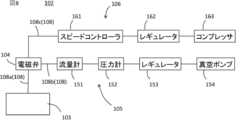
- the leak inspection device 102 includes a head 103, a solenoid valve 104, a pressure reducing system 105, a pressurizing system 106, and a pipe 108.
- the pipe 108 includes a pipe 108 a that connects the head 103 and the solenoid valve 104, a pipe 108 b that connects the decompression system 105 and the solenoid valve 104, and a pipe 108 c that connects the pressurization system 106 and the solenoid valve 104.
- the solenoid valve 104 By controlling the solenoid valve 104, it is possible to switch which of the pressure reducing system 105 and the pressurizing system 106 is connected to the head 103.
- the depressurization system 105 allows air to be sucked in through the head 103, and the pressurization system 106 allows air to be blown in through the head 103.
- the decompression system 105 includes a flow meter 151, a pressure gauge 152, a regulator 153, and a vacuum pump 154 in order from the solenoid valve 104 side.
- the vacuum pump 154 discharges the air in the pipe 108b to reduce the pressure in the pipe 108b.
- the regulator 153 controls the flow rate of the air flowing through the pipe 108b or the pressure of the air inside the pipe 108b.
- the pressure gauge 152 measures the pressure of air in the pipe 108b.
- the flowmeter 151 measures the flow rate of air flowing through the pipe 108b.
- the components included in the decompression system 105 may be changed in order or omitted as appropriate.
- the pressurization system 106 includes a speed controller 161, a regulator 162, and a compressor 163 in order from the solenoid valve 104 side.
- the compressor 163 supplies compressed air into the pipe 108c.
- the regulator 162 controls the pressure of air in the pipe 108c.
- the speed controller 161 controls the flow rate of air flowing in the pipe 108c. Note that the pressurization system 106 can be omitted if unnecessary, and in that case, the solenoid valve 104 can also be omitted.
- the head 103 includes a head base 131 and a packing 132.
- the head base 131 and the packing 132 are provided with through holes 131a and 132a, respectively, which communicate with the inside of the pipe 108a.
- the packing 132 is arranged in the accommodation recess 131 b of the head base 131.
- the packing 132 is made of a material such as an elastomer that can enhance airtightness.
- a leak inspection method for the double container 101 of this embodiment will be described. This method includes a step of determining whether or not there is a pinhole in the inner bag 114 based on the data obtained when the inside of the inner bag 114 is depressurized.
- This step can be performed by connecting the head 103 to the decompression system 105 and operating the vacuum pump 154 with the head 103 pressed against the end surface of the mouth 109.
- the air inside the inner bag 114 is sucked out to reduce the pressure inside the inner bag 114, and the inner bag 114 contracts as shown in FIG.
- the flow rate of air measured by the flow meter 151 rapidly increases, but the flow rate gradually decreases as the inner bag 114 contracts.
- the flow rate of the air becomes a very small value (nearly 0) when the inner bag 114 is deflated.
- the inner bag 114 is determined based on the flow rate of the air sucked from the inner bag 114 (more specifically, by checking whether or not this flow rate exceeds the threshold Th). It can be determined whether there is a pinhole in the.
- the degree of airtightness inside the inner bag 114 is low, and thus the degree of pressure reduction inside the inner bag 114 is less likely to increase. Therefore, with the set pressure of the vacuum pump 154 set to the reference value, it is determined whether or not there is a pinhole in the inner bag 114 based on the pressure detected by the pressure gauge 152 after a predetermined time has elapsed. You can Further, in addition to the flow rate and the pressure, it is also possible to determine the presence or absence of a pinhole based on data such as the contraction mode and contraction time of the inner bag 114. However, the determination based on the flow rate is preferable from the viewpoint of accuracy.
- the pinhole is inspected while depressurizing the inside of the inner bag 114, so it is difficult to miss the pinhole.
- the leak inspection method according to the present embodiment may be performed after performing a preliminary peeling step of peeling the inner bag 114 from the outer shell 112 in advance. It may be peeled from 112. In that case, preliminary peeling and leak inspection can be performed simultaneously, which is efficient.
- the inspection method according to the present embodiment has a significant technical significance in leak inspection in a colored double container.
- the solenoid valve 104 is operated to connect the head 103 to the pressurizing system 106, and the compressor 163 is operated in that state, whereby air is sent into the inner bag 114 and the inner bag 114 is closed. Inflate. This facilitates the step of filling the inner bag 114 with the contents.
- Second Embodiment of Second Aspect This embodiment is similar to the first embodiment, and the main difference is the configuration of the head 103. The difference will be mainly described below.
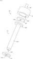
- the head 103 further includes an insertion member 133 and a packing 134.
- the insertion member 133 includes a rod portion 133a and a flange portion 133b protruding in the radial direction at the base end of the rod portion 133a.
- the packing 134 is provided with a through hole 134a, and the rod portion 133a is inserted into the through hole 134a.
- the material of the packing 134 is the same as that of the packing 132.
- the rod-shaped portion 133a is a rod-shaped portion.
- the insertion member 133 is provided with a through hole 133c, and the rod portion 133a is provided with a suction port 133d communicating with the through hole 133c.
- the suction port 133d is provided at the tip 133a1 of the rod-shaped portion 133a. Since the tip 133a1 is less likely to be covered by the inner bag 114 when the inner bag 114 contracts, the suction port 133d is provided to the tip 133a1 so that the suction port 133d is less likely to be blocked by the inner bag 114.
- the rod-shaped portion 133a is a portion to be inserted into the inner bag 114, it is preferable that the side surface and the edge of the tip of the rod-shaped portion 133a are curved so that the rod-shaped portion 133a does not damage the inner bag 114.
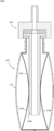
- the head base 131 when the head base 131 is pressed toward the end surface of the mouth portion 109, the head base 131, the flange portion 133b, and the end surface of the mouth portion 109 cause the packings 132 and 134 to be removed.
- the inner bag 114 is in close contact with the inner bag 114 through the through holes 131a, 132a, 133c, and the inside of the inner bag 114 can be depressurized or pressurized by the depressurization system 105 or the pressurization system 106. ..
- the inner bag 114 is decompressed while the rod-shaped portion 133a is inserted into the inner bag 114 from the mouth 109, and the inner bag 114 is contracted as shown in FIG. Then, the presence or absence of a pinhole in the inner bag 114 is confirmed. According to such a method, the following effects are exhibited.
- the inner bag 114 has a pair of opposing portions 114b and 114c that face each other with the biting portion 107d interposed therebetween.
- the inner bag 114 may be unevenly peeled and contracted so that the peeling progresses only in the portion 114b and the peeling does not progress in the portion 114c. If the inner bag 114 contracts in this way, it is a problem because the leak inspection cannot be effectively performed at the portion 114c.
- FIG. 16 As shown in FIG.
- L/H is 0.40 or more. Preferably. This is because in this case, the above two effects are effectively exhibited.
- L/H is, for example, 0.40 to 0.99, and specifically, for example, 0.40, 0.50, 0.60, 0.70, 0.80, 0.90, 0.95, 0.99, and may be in a range between any two of the numerical values exemplified here.
- D2/D1 is preferably 0.30 or more. This is because in this case, the above two effects are effectively exhibited.
- D2/D1 is, for example, 0.30 to 0.99, and specifically, for example, 0.30, 0.40, 0.50, 0.60, 0.70, 0.80, 0.90, 0.95 and 0.99, and may be in the range between any two of the numerical values exemplified here.
- L/D2 is preferably 3 or more, for example, 3 to 50, and specifically, for example, 3, 4, 5, 6, 7, 8, 9, 10, 20, 30, 40. , 50, and may be within a range between any two of the numerical values exemplified here.
- the present embodiment has excellent effects as a leak inspection method, but from the viewpoint of having the above-described two effects, it also has excellent effects as a preliminary peeling method for the double container 101. Therefore, from this viewpoint, the leak inspection is not essential.
- the suction port 133d may be provided at a portion other than the tip of the rod-shaped portion 133a.
- the suction port 133d is provided on the peripheral surface of the rod-shaped portion 133a, it is preferable that the inner bag 114 is provided at a position where it is difficult for the inner bag 114 to close the suction port 133d (eg, near the root of the rod-shaped portion 133a).
- the number of suction ports 133d may be two or more.
- the through hole 133c may be provided in the flange portion 133b. In this case, the packings 132 and 134 are provided with through holes that communicate with the through holes 133c.
- the rod-shaped portion 133a may also be provided with a through-hole 133c so as to reduce the pressure inside the inner bag 114 through both the rod-shaped portion 133a and the flange portion 133b.
- the inside of the inner bag 114 may be decompressed only from the flange 133b without providing the 133c.
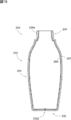
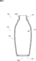
- a laminated peeling container 201 according to an embodiment of the third aspect of the present invention includes a substantially bottomed cylindrical container body 203 and a pump 204.
- the container body 203 has a bottomed tubular shape, and includes a housing portion 233 having a body portion 231 and a bottom portion 232, and a mouth portion 234 for discharging the contents from the housing portion 233. ..
- a male screw portion 234a is provided on the outer surface of the mouth portion 234.
- the container main body 203 of the present embodiment is provided with the inner bag 206 and the outer shell 207 in the accommodation portion 233 and the mouth portion 234, and the inner bag 206 is separated from the outer shell 207 as the content decreases.
- Inner bag 206 is configured to contract away from outer shell 207.
- the inner bag 206 includes an EVOH layer provided on the outer surface side of the container, an inner surface layer provided on the inner surface side of the EVOH layer, and an adhesive layer provided between the EVOH layer and the inner surface layer.
- the adhesive layer may be omitted.
- the outer shell 207 is composed of, for example, low-density polyethylene, linear low-density polyethylene, high-density polyethylene, polypropylene, ethylene-propylene copolymer and a mixture thereof.
- the pump 204 is configured to discharge the contents from the container body 203 without introducing outside air into the container body 203.
- the pump 204 includes a main body 241, a piston 242, a nozzle 243, and a tube 244.
- the main body portion 241 includes a cylinder portion 241a and a cylinder portion 241b.
- a female screw portion (not shown) to be screwed into the male screw portion 234a of the mouth portion 234 of the container body 203 is provided on the inner surface of the cylindrical portion 241a.
- the lower portion of the cylinder portion 241b is inserted into the mouth portion 234.
- the outer diameter of the cylinder portion 241b is substantially equal to the inner diameter of the mouth portion 234.
- the cylinder portion 241b has a tubular shape, and the piston portion 242 is slidable inside the cylinder portion 241b.
- the internal space of the cylinder portion 241b is in communication with the nozzle 243 and the tube 244.
- a pump mechanism including an elastic member and a valve is built in the internal space of the cylinder portion 241b.
- the bottom portion 232 of the present embodiment is provided with a pinch-off portion 232p at its central portion, as shown in FIGS. 22A, 22B and 18B, 19 and the like.
- the pinch-off portion 232p has a strip-like structure formed by sandwiching the lower end of a laminated parison P described later between the cut-off portions 221X and 221Y (see FIG. 24A) of the split molds 202X and 202Y and crushing it.
- the bottom portion 232 has a double structure of the inner bag 206 and the outer shell 207 as described above, and is configured by fitting the inner bag bottom portion 260 shown in FIG. 23A and the outer shell bottom portion 270 shown in FIG. 23B. It
- the inner bag bottom portion 260 has an inner bag protruding portion 261 that protrudes outward at the pinch-off portion 232p.
- the outer shell bottom portion 270 has a holding portion 271 that holds the inner bag protruding portion 261 in the pinch-off portion 232p.
- An outside air introduction hole 208 is provided between the inner bag protruding portion 261 and the sandwiching portion 271 (see FIGS. 22A, 23B and 18B).
- the inner bag projecting portion 261 and the sandwiching portion 271 do not project from the bottom portion 232, but may be configured to project from the bottom portion 232.
- the inner bag protruding portion 261 and the sandwiching portion 271 are attached to each other, and the outside air introduction hole 208 is not provided.
- the inner bag protruding portion 261 and the sandwiching portion 271 are easily separated, the inner bag protruding portion 261 and the sandwiching portion 261 are separated by applying an impact or a twisting force so that the inner bag protruding portion 261 and the sandwiching portion 271 are separated.
- the outside air introduction hole 208 can be formed by separating 271. Since the container body 203 has the outside air introduction hole 208, it is possible to introduce the outside air between the outer shell 207 and the inner bag 206 as the content decreases and to shrink only the inner bag 206. Is becoming
- the container body 203 of the present embodiment serves as an engaging portion that engages the inner bag 206 and the outer shell 207 with the longitudinal end portion of the pinch-off portion 232p.
- a meat reservoir 209 is formed.
- the inner bag 206 inner bag bottom portion 260
- the outer shell 207 outer shell bottom portion 270
- the outer shell 207 includes a pair of concave portions 272 that engage with the convex portions 262, as shown in FIGS. 22B and 23B.
- the convex portion 262 of the inner bag 206 and the concave portion 272 of the outer shell 207 are engaged with each other in the meat reservoir 209 in this manner, so that the inner bag 206 is reduced as the content decreases. Even when contracted, the inner bag 206 is not easily detached from the bottom portion 232.
- the convex portion 262 and the concave portion 272 of the present embodiment are integrally formed by blow molding described later, and the convex portion 262 and the concave portion 272 have a shape in which they are closely fitted to each other.
- the protrusion 262 is formed such that the protrusion amount d1 in the longitudinal direction is 0.15 times or more the length d2 in the longitudinal direction from the center X of the bottom portion 232 to the tip of the protrusion 262. It
- the ratio of d1/d2 is preferably 0.18 or more, more preferably 0.20 or more.
- the ratio of d1/d2 is, for example, 0.15 to 0.30, and more preferably 0.20 to 0.25.
- the protrusion amount d1 in the longitudinal direction of the convex portion 262 is defined as the protrusion amount from the most constricted position of the inner bag bottom portion 260 in the cross section of the inner bag bottom portion 260 at the pinch-off portion 232p, as shown in FIG. 22B. To be done.
- the length of the protrusion amount d1 is specifically formed to be 1.5 mm or more.
- the protrusion amount d1 is preferably 2.0 mm or more. Further, the protrusion amount d1 is preferably 2.0 mm to 6.0 mm, more preferably 2.5 mm to 5.5 mm, and further preferably 3.5 mm to 4.5 mm.
- the specific value of the protrusion amount d1 is, for example, 2.0, 2.1, 2.2, 2.3, 2.4, 2.5, 2.6, 2.7, 2.8, 2. .9, 3.0, 3.1, 3.2, 3.3, 3.4, 3.5, 3.6, 3.7, 3.8, 3.9, 4.0, 4.1.
- the tip of the convex portion 262 of the present embodiment projects to a position substantially the same as the edge of the bottom surface of the inner bag 206 in the radial direction.
- the tip of the convex portion 262 may remain at a position inside the edge of the bottom surface of the inner bag 206 as long as the protrusion amount dl of the convex portion 262 can be sufficiently secured.
- the container body 203 is formed by blow molding a cylindrical laminated parison P extruded from the extruder 205, as shown in FIGS. 24A and 24B.
- the laminated parison P is extruded from a die 205a (die head) in a molten state, and this is clamped by a pair of split molds 202X and 202Y of the blow molding mold 202.
- the split molds 202X and 202Y have a cavity shape such that various shapes of the container body 203 such as the body portion 231, the bottom portion 232, and the mouth portion 234 are formed into a blow-molded product.
- the die diameter of the die 205a for extruding the laminated parison is the diameter of the portion forming the bottom of the inner diameter of the split mold 202X, 202Y.
- the inner diameter that is, 2/ ⁇ times or less of the diameter d4 of the bottom portion 232 (bottom surface).
- the fold diameter that is the width of the crushed laminated parison P (the width of the pinch-off portion 232p after molding and Is approximately smaller than the inner diameter d4 of the portion forming the bottom portion 232 of the container body 203.
- the ratio of d3/d4 is, for example, 0.1 to 0.63, and more preferably 0.19 to 0.42.
- the ratio of d3/d4 is specifically, for example, 0.19, 0.20, 0.21, 0.22, 0.23, 0.24, 0.25, 0.26, 0.27, 0. .28, 0.29, 0.30, 0.31, 0.32, 0.33, 0.34, 0.35, 0.36, 0.37, 0.38, 0.39, 0.40 , 0.41, 0.42, and may be in the range between any two of the numerical values exemplified here.
- the diameter d3 of the laminated parison P is, as shown in FIG. 24B, slightly smaller than the inner diameter d5 of the portion forming the mouth 234 of the container main body 203 in the inner diameter of the blow molding die 202.
- the ratio of d3/d5 is, for example, 0.6 to 0.9, and more preferably 0.7 to 0.8.
- the ratio of d3/d5 is specifically, for example, 0.70, 0.71, 0.72, 0.73, 0.74, 0.75, 0.76, 0.77, 0.78. , 0.79, 0.80, and may be in a range between any two of the numerical values exemplified here.
- the diameter d3 of the laminated parison P is too large with respect to the inner diameter d5 of the portion forming the mouth portion 234, burr biting or the like may occur during mold clamping, and if the diameter d3 of the laminated parison P is too thin, blown.
- the ratio becomes too large and molding becomes difficult.
- the mouth portion 234 can be suitably formed.
- the split molds 202X and 202Y of the blow molding mold 202 are provided with cut-off portions 221X and 221Y, respectively.
- the blow molding die 202 includes a compression portion 222 below the bite cutting portions 221X and 221Y.
- the compression part 222 is formed by the split molds 202X and 202Y and compresses the laminated parison P during mold clamping.
- the compression part 222 includes a first compression region 222a and a first compression region 222a, which are formed at positions near both ends in the longitudinal direction of the bite cutting parts 221X and 221Y. And a second compression region 222b arranged at a position between them.
- the width d6 of the first compression region 222a when the mold is clamped is narrower than the width d7 of the second compression region 222a when the mold is clamped.
- the width d6 of the first compression region 222a at the time of mold clamping is preferably set to be equal to or less than the thickness d8 (see FIG. 26A) of the laminated parison P.
- the width d6 of the first compression region 222a when the mold is clamped is preferably 1 mm or less, and more preferably 0.2 mm or less. Further, the width d6 is preferably such that the dies do not come into complete contact with each other, and is preferably 0.01 mm or more.
- the value of the width d6 is, for example, 0.01 mm to 1.00 mm, preferably 0.05 mm to 0.20 mm. Specifically, for example, 0.05, 0.06, 0.07, 0.08, 0.09, 0.10, 0.11, 0.12, 0.13, 0.14, 0.15. It is 0.16, 0.17, 0.18, 0.19, 0.20 mm, and may be in a range between any two of the numerical values exemplified here.
- the width d7 of the second compression region 222b when the mold is clamped is equal to or less than twice the thickness d8 of the laminated parison P.
- the width d7 is preferably 10 mm or less, and more preferably 8 mm or less.
- the value of the width d7 is, for example, 1.0 mm to 6.0 mm, more preferably 2.0 mm to 5.0 mm, and further preferably 3.0 mm to 4.0 mm.
- FIGS. 26A to 26C show a state in which the laminated parison P is hung on the blow molding die 202 having the above-described configuration, and the pair of split dies 202X and 202Y are gradually closed. It is a thing.
- the split molds 202X and 202Y are closed from the state before clamping in FIG. 26A, the cylindrical laminated parison P is pressed inward by the cut-off portions 221X and 221Y of the split molds 202X and 202Y, and FIG. As shown, first, the inner surfaces (layers forming the inner bag 206) of the laminated parison P contact each other.
- the laminated parison P is compressed by the bite cutting portions 221X and 221Y and the compression portion 222. Then, as shown in FIG. 26C, when the mold is completely closed, the laminated parison P is separated into two by the cut-off portions 221X and 221Y, and the pinch-off portion 232p is formed on the container side.
- the laminated parison P is gradually compressed.
- the laminated parison P is positioned below (above the container) above (the inside of the container) the bite parts 221X and 221Y. More compressed. Therefore, the crushed laminated parison P is likely to flow in the container inner direction (see the arrow in FIG. 26B) having a large space.
- the compression part 222 of the present embodiment includes the first compression region 222a and the second compression region 222b, and the width d6 of the first compression region 222a near both ends in the longitudinal direction of the bite parts 221X and 221Y is the first. It is configured to be narrower than the width d7 of the two compression regions 222b.
- the laminated parison P crushed by the compression portion 222 is prevented from spreading in the lateral direction (longitudinal direction of the cut-off portions 221X and 221Y, the left-right direction in FIG. 24B). Therefore, the laminated parison P moves in the vertical direction and is pushed back into the cavity, so that the laminated parison P is more likely to flow in the container inward direction.
- the protrusion amount d1 of the convex portion 262 of the inner bag 206 can be increased, the fitting with the concave portion 272 of the outer shell 207 can be strengthened, and the detachment of the inner bag 206 from the bottom portion 232 can be suppressed. It is possible.
- the laminated parison P was compressed by the compression part 222.
- the width of the compression portion 222 is constant, the protrusion amount d1 of the convex portion 262 of the inner bag 206 cannot be sufficiently obtained.
- the compression portion 222 is composed of the above-described first compression region 222a and second compression region 222b, the protrusion amount d1 can be increased.
- the ratio d1/d2 of the protrusion amount d1 in the longitudinal direction of the convex portion 262 and the length d2 in the longitudinal direction from the center X of the bottom portion 232 to the tip of the convex portion 262 can also be increased as described above. Has become. (See Figure 22B).
- the convex portion 262 of the inner bag 206 is engaged with the concave portion 272 of the outer shell 207 in the meat reservoir 209, so that the inner bag 206 moves from the bottom portion 232.
- it is difficult to remove the inner bag 206 it does not mean that the inner bag 206 is not removed at all. That is, since the convex portion 262 of the inner bag 206 is only engaged with the concave portion 272 of the outer shell 207, the remaining amount of the contents in the laminated peeling container 201 is small, and the shrinkage amount of the inner bag 206 is small.
- the convex portion 262 and the concave portion 272 are disengaged due to the deformation of the inner bag 206.
- the inner bag 206 can be more freely deformed, and it is possible to collect the contents at the end of the tube 244 by suction of the pump 204 and discharge the contents to the end.
- the invention of the third aspect can also be implemented in the following modes.
- the pair of split molds 202X and 202Y of the blow molding mold 202 are configured to completely abut at the outer position of the first compression region 222a.
- the blow molding die 202 of the present invention is not limited to such a configuration. That is, as shown in FIG. 27A, the first compression region 222a may be continuous to the end of the mold. Further, as shown in FIG.
- the gap between the pair of split molds 202X and 202Y is the first compression region.
- the width d6 of the 222a may be larger than the width d6.
- the laminated peeling container 201 is configured to discharge the contents by the pump 204, but it is also possible to squeeze the container body 203 to discharge the contents.
- the outside air introduction hole 208 is provided in the bottom portion 232, but it may be provided in the body portion 231. Further, in this case, it is also preferable to provide a valve member in the outside air introduction hole 208.
- D2 length from the center of the bottom portion to the tip of the convex portion
- d3 diameter of the laminated parison P
- d4 diameter of the bottom portion
- d5 inner diameter of the portion forming the mouth portion
- d6 width of the first compression region
- d7 width of second compression region
- d8 thickness of laminated parison P
Landscapes
- Engineering & Computer Science (AREA)
- Mechanical Engineering (AREA)
- Ceramic Engineering (AREA)
- Containers And Packaging Bodies Having A Special Means To Remove Contents (AREA)
- Containers Having Bodies Formed In One Piece (AREA)
- Packages (AREA)
- Closures For Containers (AREA)
Abstract
L'invention concerne un récipient à capuchon capable d'empêcher un débordement d'un capuchon. L'invention concerne un récipient à capuchon comprenant un corps de récipient et un capuchon. Le capuchon comprend une partie de vis femelle. Le corps de récipient comprend une partie de vis mâle qui vient en prise par filetage avec la partie de vis femelle au niveau d'une partie d'embouchure. Le capuchon comprend une saillie au niveau d'une position plus près d'un côté du corps de récipient que la partie de vis femelle. Le corps de récipient comprend une partie de mise en marche qui vient en prise avec la saillie pour limiter le relâchement du capuchon, et une partie de butée qui est positionnée plus près d'un côté d'une direction de fixation de vis que la partie de mise en marche et limite un débordement du capuchon.
Priority Applications (1)
| Application Number | Priority Date | Filing Date | Title |
|---|---|---|---|
| CN201980064280.3A CN112770978B (zh) | 2018-11-30 | 2019-11-26 | 带盖容器 |
Applications Claiming Priority (6)
| Application Number | Priority Date | Filing Date | Title |
|---|---|---|---|
| JP2018-224637 | 2018-11-30 | ||
| JP2018224637A JP7212250B2 (ja) | 2018-11-30 | 2018-11-30 | キャップ付き容器 |
| JP2019-007950 | 2019-01-21 | ||
| JP2019007950A JP7137075B2 (ja) | 2019-01-21 | 2019-01-21 | 積層剥離容器 |
| JP2019020958A JP7323765B2 (ja) | 2019-02-07 | 2019-02-07 | 二重容器のリーク検査方法及び予備剥離方法 |
| JP2019-020958 | 2019-02-07 |
Publications (1)
| Publication Number | Publication Date |
|---|---|
| WO2020111024A1 true WO2020111024A1 (fr) | 2020-06-04 |
Family
ID=70853487
Family Applications (1)
| Application Number | Title | Priority Date | Filing Date |
|---|---|---|---|
| PCT/JP2019/046063 Ceased WO2020111024A1 (fr) | 2018-11-30 | 2019-11-26 | Récipient à capuchon, procédé d'examen de fuite pour récipient double, récipient de libération de lamination, et son procédé de fabrication |
Country Status (3)
| Country | Link |
|---|---|
| CN (1) | CN112770978B (fr) |
| TW (1) | TWI827742B (fr) |
| WO (1) | WO2020111024A1 (fr) |
Families Citing this family (1)
| Publication number | Priority date | Publication date | Assignee | Title |
|---|---|---|---|---|
| JP7013610B1 (ja) * | 2021-05-17 | 2022-01-31 | 株式会社アイセロ | 容器及び容器組立体 |
Citations (8)
| Publication number | Priority date | Publication date | Assignee | Title |
|---|---|---|---|---|
| JPH0731640U (ja) * | 1993-11-19 | 1995-06-13 | 吉田工業株式会社 | 位置合せ容器 |
| JPH08151061A (ja) * | 1994-11-30 | 1996-06-11 | Yoshino Kogyosho Co Ltd | キャップ付き容器 |
| JP3303234B2 (ja) * | 1997-09-17 | 2002-07-15 | 株式会社吉野工業所 | 二重ブロー成形壜体の内容器リーク検査方法 |
| US20030146183A1 (en) * | 2002-02-04 | 2003-08-07 | Rexam Medical Packaging Inc. | Rotary seal for closure with on-stop |
| JP2006306460A (ja) * | 2005-04-28 | 2006-11-09 | Kyoraku Co Ltd | 密封容器の首部の緩衝構造 |
| JP2013199296A (ja) * | 2012-03-23 | 2013-10-03 | Daiwa Can Co Ltd | 樹脂容器 |
| JP2016159935A (ja) * | 2015-02-27 | 2016-09-05 | 株式会社吉野工業所 | 二重容器 |
| JP2017057009A (ja) * | 2015-09-15 | 2017-03-23 | 天龍化学工業株式会社 | ねじ蓋式容器 |
Family Cites Families (11)
| Publication number | Priority date | Publication date | Assignee | Title |
|---|---|---|---|---|
| JP2007176543A (ja) * | 2005-12-27 | 2007-07-12 | Kao Corp | キャップ付き容器 |
| KR101210435B1 (ko) * | 2010-11-11 | 2012-12-10 | (주)연우 | 안전캡 |
| ES2535320T3 (es) * | 2010-12-23 | 2015-05-08 | Obrist Closures Switzerland Gmbh | Cierre para un envase |
| KR20150143815A (ko) * | 2013-07-12 | 2015-12-23 | 도칸 고교 가부시키가이샤 | 캡 조립체 및 그 타전 방법 |
| TWI642600B (zh) * | 2014-02-12 | 2018-12-01 | 日商京洛股份有限公司 | 積層剝離容器,其針孔檢查方法,及其加工方法 |
| JP6761159B2 (ja) * | 2014-11-19 | 2020-09-23 | キョーラク株式会社 | 積層剥離容器 |
| KR101995407B1 (ko) * | 2014-12-19 | 2019-07-02 | 교라꾸 가부시끼가이샤 | 적층박리용기 및 적층박리용기로의 캡의 장착 방법 |
| JP6675069B2 (ja) * | 2015-05-28 | 2020-04-01 | キョーラク株式会社 | 二重容器 |
| CN107614387B (zh) * | 2015-05-28 | 2019-11-15 | 京洛株式会社 | 双层容器 |
| US11248945B2 (en) * | 2015-09-01 | 2022-02-15 | Franklin Fueling Systems, Inc. | Tank maintenance access chamber |
| CN206590291U (zh) * | 2017-02-23 | 2017-10-27 | 东莞市鑫宇制罐有限公司 | 一种螺旋铁罐 |
-
2019
- 2019-11-26 WO PCT/JP2019/046063 patent/WO2020111024A1/fr not_active Ceased
- 2019-11-26 CN CN201980064280.3A patent/CN112770978B/zh active Active
- 2019-11-28 TW TW108143356A patent/TWI827742B/zh active
Patent Citations (8)
| Publication number | Priority date | Publication date | Assignee | Title |
|---|---|---|---|---|
| JPH0731640U (ja) * | 1993-11-19 | 1995-06-13 | 吉田工業株式会社 | 位置合せ容器 |
| JPH08151061A (ja) * | 1994-11-30 | 1996-06-11 | Yoshino Kogyosho Co Ltd | キャップ付き容器 |
| JP3303234B2 (ja) * | 1997-09-17 | 2002-07-15 | 株式会社吉野工業所 | 二重ブロー成形壜体の内容器リーク検査方法 |
| US20030146183A1 (en) * | 2002-02-04 | 2003-08-07 | Rexam Medical Packaging Inc. | Rotary seal for closure with on-stop |
| JP2006306460A (ja) * | 2005-04-28 | 2006-11-09 | Kyoraku Co Ltd | 密封容器の首部の緩衝構造 |
| JP2013199296A (ja) * | 2012-03-23 | 2013-10-03 | Daiwa Can Co Ltd | 樹脂容器 |
| JP2016159935A (ja) * | 2015-02-27 | 2016-09-05 | 株式会社吉野工業所 | 二重容器 |
| JP2017057009A (ja) * | 2015-09-15 | 2017-03-23 | 天龍化学工業株式会社 | ねじ蓋式容器 |
Also Published As
| Publication number | Publication date |
|---|---|
| TW202030462A (zh) | 2020-08-16 |
| CN112770978B (zh) | 2022-12-16 |
| CN112770978A (zh) | 2021-05-07 |
| TWI827742B (zh) | 2024-01-01 |
Similar Documents
| Publication | Publication Date | Title |
|---|---|---|
| EP1422160B1 (fr) | Recipient verseur | |
| US10822135B2 (en) | Delaminatable container | |
| KR101493534B1 (ko) | 다이렉트 블로우 성형방법에 의한 합성수지제 이중 용기 | |
| KR100338994B1 (ko) | 적층박리용기와 그 관련기술 | |
| JP6112385B2 (ja) | ブロー成形容器及びその製造方法 | |
| US7832594B2 (en) | Liquid storage container with bottom filter | |
| TW201917065A (zh) | 層疊剝離容器 | |
| AU2015326365A1 (en) | Delamination container | |
| US20170283115A1 (en) | Double container assembly and manufacturing method therefor | |
| WO2020111024A1 (fr) | Récipient à capuchon, procédé d'examen de fuite pour récipient double, récipient de libération de lamination, et son procédé de fabrication | |
| JP4405775B2 (ja) | フィルター付き吐出容器 | |
| KR102227322B1 (ko) | 이중 용기 및 그 제조 방법 | |
| JP2020023352A (ja) | 二重容器 | |
| JP2019210003A (ja) | 積層剥離容器 | |
| JP2006335398A (ja) | 内側層が剥離可能な積層容器その成形方法 | |
| JP2014091531A (ja) | ブロー成形容器 | |
| JP2019081591A (ja) | 二重容器用キャップ | |
| CN209939383U (zh) | 一种新型打气盖 | |
| CN112849725A (zh) | 一种低成本的双层瓶 | |
| JP7137075B2 (ja) | 積層剥離容器 | |
| JP2026014160A (ja) | 二重容器、及びその製造方法 | |
| JP2006062715A (ja) | シーリング剤の保管・注入容器 | |
| JPH0632339Y2 (ja) | 多層ブロー成形機におけるパリソンヘッド | |
| HK1262191B (en) | Double-layered container and method for production of same | |
| JP2021053972A (ja) | プリフォーム組立体、積層剥離容器、及び積層剥離容器の製造方法 |
Legal Events
| Date | Code | Title | Description |
|---|---|---|---|
| 121 | Ep: the epo has been informed by wipo that ep was designated in this application |
Ref document number: 19891528 Country of ref document: EP Kind code of ref document: A1 |
|
| NENP | Non-entry into the national phase |
Ref country code: DE |
|
| 122 | Ep: pct application non-entry in european phase |
Ref document number: 19891528 Country of ref document: EP Kind code of ref document: A1 |