WO2020111259A1 - Plaque originale d'impression planographique, procédé de production de plaque d'impression planographique, et procédé d'impression planographique - Google Patents
Plaque originale d'impression planographique, procédé de production de plaque d'impression planographique, et procédé d'impression planographique Download PDFInfo
- Publication number
- WO2020111259A1 WO2020111259A1 PCT/JP2019/046871 JP2019046871W WO2020111259A1 WO 2020111259 A1 WO2020111259 A1 WO 2020111259A1 JP 2019046871 W JP2019046871 W JP 2019046871W WO 2020111259 A1 WO2020111259 A1 WO 2020111259A1
- Authority
- WO
- WIPO (PCT)
- Prior art keywords
- group
- printing plate
- lithographic printing
- compound
- plate precursor
- Prior art date
- Legal status (The legal status is an assumption and is not a legal conclusion. Google has not performed a legal analysis and makes no representation as to the accuracy of the status listed.)
- Ceased
Links
Images






Classifications
-
- B—PERFORMING OPERATIONS; TRANSPORTING
- B41—PRINTING; LINING MACHINES; TYPEWRITERS; STAMPS
- B41C—PROCESSES FOR THE MANUFACTURE OR REPRODUCTION OF PRINTING SURFACES
- B41C1/00—Forme preparation
- B41C1/10—Forme preparation for lithographic printing; Master sheets for transferring a lithographic image to the forme
- B41C1/1008—Forme preparation for lithographic printing; Master sheets for transferring a lithographic image to the forme by removal or destruction of lithographic material on the lithographic support, e.g. by laser or spark ablation; by the use of materials rendered soluble or insoluble by heat exposure, e.g. by heat produced from a light to heat transforming system; by on-the-press exposure or on-the-press development, e.g. by the fountain of photolithographic materials
-
- B—PERFORMING OPERATIONS; TRANSPORTING
- B41—PRINTING; LINING MACHINES; TYPEWRITERS; STAMPS
- B41N—PRINTING PLATES OR FOILS; MATERIALS FOR SURFACES USED IN PRINTING MACHINES FOR PRINTING, INKING, DAMPING, OR THE LIKE; PREPARING SUCH SURFACES FOR USE AND CONSERVING THEM
- B41N1/00—Printing plates or foils; Materials therefor
- B41N1/12—Printing plates or foils; Materials therefor non-metallic other than stone, e.g. printing plates or foils comprising inorganic materials in an organic matrix
- B41N1/14—Lithographic printing foils
-
- G—PHYSICS
- G03—PHOTOGRAPHY; CINEMATOGRAPHY; ANALOGOUS TECHNIQUES USING WAVES OTHER THAN OPTICAL WAVES; ELECTROGRAPHY; HOLOGRAPHY
- G03F—PHOTOMECHANICAL PRODUCTION OF TEXTURED OR PATTERNED SURFACES, e.g. FOR PRINTING, FOR PROCESSING OF SEMICONDUCTOR DEVICES; MATERIALS THEREFOR; ORIGINALS THEREFOR; APPARATUS SPECIALLY ADAPTED THEREFOR
- G03F7/00—Photomechanical, e.g. photolithographic, production of textured or patterned surfaces, e.g. printing surfaces; Materials therefor, e.g. comprising photoresists; Apparatus specially adapted therefor
-
- G—PHYSICS
- G03—PHOTOGRAPHY; CINEMATOGRAPHY; ANALOGOUS TECHNIQUES USING WAVES OTHER THAN OPTICAL WAVES; ELECTROGRAPHY; HOLOGRAPHY
- G03F—PHOTOMECHANICAL PRODUCTION OF TEXTURED OR PATTERNED SURFACES, e.g. FOR PRINTING, FOR PROCESSING OF SEMICONDUCTOR DEVICES; MATERIALS THEREFOR; ORIGINALS THEREFOR; APPARATUS SPECIALLY ADAPTED THEREFOR
- G03F7/00—Photomechanical, e.g. photolithographic, production of textured or patterned surfaces, e.g. printing surfaces; Materials therefor, e.g. comprising photoresists; Apparatus specially adapted therefor
- G03F7/004—Photosensitive materials
-
- G—PHYSICS
- G03—PHOTOGRAPHY; CINEMATOGRAPHY; ANALOGOUS TECHNIQUES USING WAVES OTHER THAN OPTICAL WAVES; ELECTROGRAPHY; HOLOGRAPHY
- G03F—PHOTOMECHANICAL PRODUCTION OF TEXTURED OR PATTERNED SURFACES, e.g. FOR PRINTING, FOR PROCESSING OF SEMICONDUCTOR DEVICES; MATERIALS THEREFOR; ORIGINALS THEREFOR; APPARATUS SPECIALLY ADAPTED THEREFOR
- G03F7/00—Photomechanical, e.g. photolithographic, production of textured or patterned surfaces, e.g. printing surfaces; Materials therefor, e.g. comprising photoresists; Apparatus specially adapted therefor
- G03F7/004—Photosensitive materials
- G03F7/027—Non-macromolecular photopolymerisable compounds having carbon-to-carbon double bonds, e.g. ethylenic compounds
- G03F7/028—Non-macromolecular photopolymerisable compounds having carbon-to-carbon double bonds, e.g. ethylenic compounds with photosensitivity-increasing substances, e.g. photoinitiators
-
- G—PHYSICS
- G03—PHOTOGRAPHY; CINEMATOGRAPHY; ANALOGOUS TECHNIQUES USING WAVES OTHER THAN OPTICAL WAVES; ELECTROGRAPHY; HOLOGRAPHY
- G03F—PHOTOMECHANICAL PRODUCTION OF TEXTURED OR PATTERNED SURFACES, e.g. FOR PRINTING, FOR PROCESSING OF SEMICONDUCTOR DEVICES; MATERIALS THEREFOR; ORIGINALS THEREFOR; APPARATUS SPECIALLY ADAPTED THEREFOR
- G03F7/00—Photomechanical, e.g. photolithographic, production of textured or patterned surfaces, e.g. printing surfaces; Materials therefor, e.g. comprising photoresists; Apparatus specially adapted therefor
- G03F7/004—Photosensitive materials
- G03F7/09—Photosensitive materials characterised by structural details, e.g. supports, auxiliary layers
Definitions
- the present disclosure relates to a lithographic printing plate precursor, a method for producing a lithographic printing plate, and a lithographic printing method.
- a lithographic printing plate comprises a lipophilic image area that receives ink during the printing process and a hydrophilic non-image area that receives fountain solution.
- the lipophilic image part of the lithographic printing plate is used as the ink receiving part and the hydrophilic non-image part is dampening water receiving part (ink non-receiving part) by utilizing the property that water and oil-based ink repel each other.
- a difference in ink adhesion is caused on the surface of the lithographic printing plate, the ink is applied only to the image portion, and then the ink is transferred to a printing medium such as paper for printing.
- a lithographic printing plate precursor in which a lipophilic photosensitive resin layer (image recording layer) is provided on a hydrophilic support has been widely used.
- the lithographic printing plate precursor is exposed through an original image such as a lith film, and then a portion which becomes an image portion of the image recording layer is left, and the other unnecessary image recording layer is treated with an alkaline developer or an organic solvent.
- a lithographic printing plate is obtained by carrying out plate making by a method of dissolving and removing with a solvent and exposing the hydrophilic support surface to form a non-image area.
- Patent Document 1 discloses a support having a hydrophilic surface or a support provided with a hydrophilic layer and a coating provided on the support, which includes hydrophobic thermoplastic polymer particles, a binder and an infrared absorbing dye.
- a coating including an image recording layer; the hydrophobic thermoplastic polymer particles have an average particle diameter measured by photon correlation spectroscopy of 10 nm or more and less than 40 nm, and the amount of the IR dye does not consider any counter ion.
- 0.80 mg/m 2 of the total surface area of the thermoplastic polymer particles as determined by hydrodynamic fractionation, and the amount of the hydrophobic thermoplastic polymer particles based on the total weight of the components of the imaging layer is at least 60%.
- a heat-sensitive negative lithographic printing plate precursor is described.
- Patent Document 2 discloses a lithographic substrate; and a) a radical-polymerizable component; b) an initiator system capable of generating sufficient radicals to initiate a polymerization reaction when exposed to image-forming radiation; And c) a structural unit having a hydrophobic backbone and i) a pendant cyano group directly attached to the hydrophobic backbone, and ii) a pendant group comprising a hydrophilic poly(alkylene oxide) segment.
- An imageable element is described that comprises a polymeric binder that includes both of the constituent units having
- Patent Document 1 European Patent Application Publication No. 1,859,935
- Patent Document 2 Japanese Patent Publication No. 2008-503365
- planographic printing plate a planographic printing plate excellent in the number of printable plates (hereinafter, also referred to as “printing durability”) is required.
- an ink for printing an ink that is cured by irradiation with ultraviolet rays (UV) (also referred to as “ultraviolet curable ink or UV ink”) may be used.
- UV ink has high productivity because it can be dried instantly, generally has a low content of solvent, or it is easy to reduce environmental pollution because it is solvent-free. Do not dry with heat, or dry with heat. Since an image can be formed in a short time, it has an advantage that the range of applications such as printing targets is expanded.
- a lithographic printing plate precursor capable of providing a lithographic printing plate excellent in printing durability even when using a UV ink is considered to be very useful industrially.
- the present inventor found that the lithographic printing plate precursor described in Patent Document 1 or Patent Document 2 had insufficient printing durability, particularly when UV ink was used as the ink. I found that there is.
- the problem to be solved by one embodiment of the present disclosure is to provide a lithographic printing plate precursor having excellent printing durability even when UV ink is used in the obtained lithographic printing plate.
- a problem to be solved by another embodiment of the present disclosure is to provide a method for producing a planographic printing plate using the planographic printing plate precursor, or a planographic printing method.
- Means for solving the above problems include the following aspects.
- a lithographic printing plate precursor which has an image recording layer on a support, and the image recording layer contains an infrared absorber, a polymerization initiator, a polymerizable compound, and thermoplastic resin particles.
- thermoplastic resin contained in the thermoplastic resin particles contains a structural unit formed of an aromatic vinyl compound, and a resin A having a structural unit having a cyano group
- ⁇ 4> The lithographic printing plate precursor as described in any one of ⁇ 1> to ⁇ 3>, in which the thermoplastic resin contained in the thermoplastic resin particles has a hydrophilic group.
- thermoplastic resin contained in the thermoplastic resin particles has a polyalkylene oxide structure as the hydrophilic group.
- thermoplastic resin particles have an arithmetic average particle diameter of 1 nm or more and less than 80 nm.
- ⁇ 8> The lithographic printing plate precursor as described in any one of ⁇ 1> to ⁇ 7> above, wherein the polymerization initiator contains an electron-accepting polymerization initiator.
- the electron accepting polymerization initiator has a LUMO of ⁇ 3.0 eV or less.
- the difference between the LUMO of the electron-accepting polymerization initiator and the LUMO of the infrared absorber is 0.70 eV or less.
- ⁇ 11> The lithographic printing plate precursor as described in any one of ⁇ 1> to ⁇ 10>, in which the polymerization initiator further contains an electron donating polymerization initiator.
- ⁇ 12> The lithographic printing plate precursor as described in ⁇ 11>, in which the difference between the HOMO of the infrared absorber and the HOMO of the electron-donating polymerization initiator is 0.70 eV or less.
- ⁇ 13> The lithographic printing plate precursor as described in any one of ⁇ 1> to ⁇ 12>, wherein the infrared absorber is a cationic polymethine dye having an oxygen atom or a nitrogen atom at a meso position.
- ⁇ 14> The lithographic printing plate precursor as described in any one of ⁇ 1> to ⁇ 13>, wherein the infrared absorber is a decomposable infrared absorber that decomposes due to heat caused by infrared exposure and electron transfer. . ⁇ 15> The lithographic printing plate precursor as described in ⁇ 14>, wherein the decomposable infrared absorbent is an infrared absorbent represented by the following formula 1-1.
- R 1 represents a group represented by Formula 2 below, and R 11 to R 18 each independently represent a hydrogen atom, a halogen atom, —R a , —OR b , —SR c or —NR.
- R e , R a to R e each independently represents a hydrocarbon group, and A 1 , A 2 and a plurality of R 11 to R 18 may combine to form a monocyclic or polycyclic ring.
- a 1 and A 2 each independently represent an oxygen atom, a sulfur atom or a nitrogen atom
- n 11 and n 12 each independently represent an integer of 0 to 5, provided that the sum of n 11 and n 12 is 2 or more
- n 13 and n 14 each independently represent 0 or 1
- L represents an oxygen atom, a sulfur atom or —NR 10 —
- R 10 represents a hydrogen atom, an alkyl group or an aryl group
- Za represents a counter ion that neutralizes the charge.
- R Z represents an alkyl group
- the wavy line represents the bonding site with the group represented by L in Formula 1-1.
- ⁇ 16> The planographic printing plate according to any one of ⁇ 1> to ⁇ 15>, in which the content of the infrared absorbent is 0.1% by mass to 10% by mass based on the total mass of the image recording layer.
- ⁇ 17> The lithographic printing plate precursor as described in any one of ⁇ 1> to ⁇ 16>, wherein the polymerizable compound has an ethylenically unsaturated bond equivalent of 200 g/mol or less.
- ⁇ 18> The lithographic printing plate precursor as described in any one of ⁇ 1> to ⁇ 17>, wherein the polymerizable compound has a weight average molecular weight of 1,500 or less.
- ⁇ 19> The lithographic printing plate precursor as described in any one of ⁇ 1> to ⁇ 18>, wherein the polymerizable compound contains a trifunctional or higher functional polymerizable compound.
- ⁇ 20> The lithographic printing plate precursor as described in any one of ⁇ 1> to ⁇ 18>, in which the polymerizable compound has a 7-functional or higher-functional polymerizable group.
- ⁇ 21> The lithographic printing plate precursor as described in any one of ⁇ 1> to ⁇ 18>, in which the polymerizable compound has a 10- or more-functional polymerizable group.
- ⁇ 22> The lithographic printing plate precursor as described in any one of ⁇ 1> to ⁇ 21>, in which the image recording layer contains two or more polymerizable compounds.
- ⁇ 23> The lithographic printing plate precursor as described in any one of ⁇ 1> to ⁇ 22>, wherein the image recording layer further contains an acid color developing agent.
- ⁇ 24> The lithographic printing plate precursor as described in any one of ⁇ 1> to ⁇ 23>, wherein the image recording layer further contains a development accelerator.
- ⁇ 25> The lithographic printing plate precursor as described in any one of ⁇ 1> to ⁇ 24>, wherein the image recording layer further contains an oil sensitizer.
- the support has micropores on the image recording layer side surface, The lithographic printing plate precursor as described in any one of ⁇ 1> to ⁇ 25>, wherein the average diameter of the micropores on the surface is more than 13 nm and 100 nm or less.
- the support has an anodic oxide coating on the surface on the image recording layer side,
- the anodized film has the micropores extending in the depth direction from the surface of the anodized film on the image recording layer side,
- the micropores have large-diameter pores extending from the surface of the anodized film to a depth of 10 nm to 1,000 nm.
- a small-diameter hole communicating with the bottom of the large-diameter hole and extending from the communicating position to a depth of 20 nm to 2,000 nm.
- the average diameter of the large-diameter holes is more than 13 nm and 100 nm or less
- a step of exposing the lithographic printing plate precursor according to any one of ⁇ 1> to ⁇ 26> in an imagewise manner A method for producing a lithographic printing plate, comprising the step of supplying at least one selected from the group consisting of printing ink and fountain solution on a printing machine to remove the image recording layer in the non-image area.
- a lithographic printing plate precursor having excellent printing durability even when UV ink is used in the obtained lithographic printing plate. Further, according to another embodiment of the present disclosure, it is possible to provide a method for producing a planographic printing plate using the planographic printing plate precursor or a method for printing a planographic printing plate.
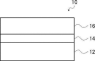
- FIG. 1 is a schematic cross-sectional view of an embodiment of a lithographic printing plate precursor according to the present disclosure.
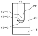
- FIG. 3 is a schematic cross-sectional view of one embodiment of an aluminum support having an anodized film. It is the schematic sectional drawing which expanded one of the micropores in FIG. 2A.
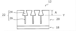
- FIG. 6 is a schematic cross-sectional view of another embodiment of an aluminum support having an anodized film.
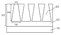
- FIG. 6 is a schematic cross-sectional view of another embodiment of an aluminum support having an anodized film.
- FIG. 6 is a schematic cross-sectional view of another embodiment of an aluminum support having an anodized film.
- FIG. 6 is a schematic cross-sectional view of another embodiment of an aluminum support having an anodized film.
- FIG. 6 is a schematic cross-sectional view of another embodiment of an aluminum support having an anodized film.
- FIG. 3 is a schematic cross-sectional view of an aluminum support having an anodic oxide coating, which shows a process sequence from a first anodizing process to a second anodizing process. It is a graph which shows an example of the alternating waveform current waveform diagram used for the electrochemical graining treatment in the manufacturing method of the aluminum support body which has an anodized film. It is a side view which shows an example of the radial type cell in the electrochemical graining treatment using alternating current in the manufacturing method of the aluminum support body which has an anodized film. It is a side view which shows the concept of the process of brush graining used for the mechanical roughening process in the manufacturing method of the aluminum support which has an anodized film.
- FIG. 3 is a schematic view of an anodizing apparatus used for anodizing in the method for producing an aluminum support having an anodized film.
- the “alkyl group” includes not only an alkyl group having no substituent (unsubstituted alkyl group) but also an alkyl group having a substituent (substituted alkyl group).
- (meth)acrylic is a term used as a concept including both acryl and methacryl
- (meth)acryloyl is a term used as a concept including both acryloyl and methacryloyl.
- the term “process” in the present specification refers to not only an independent process but also the case where it cannot be clearly distinguished from other processes as long as the intended purpose of the process is achieved. included.
- each component in the composition or each structural unit in the polymer may be contained alone or in combination of two or more.
- the amount of each component in the composition or each constituent unit in the polymer is such that there are a plurality of substances or constituent units corresponding to each component in the composition or each constituent unit in the polymer. In this case, unless otherwise specified, it means the total amount of the corresponding substances present in the composition or the respective constituent units present in the polymer.
- a combination of two or more preferable aspects is a more preferable aspect.
- the weight average molecular weight (Mw) and the number average molecular weight (Mn) in the present disclosure are columns of TSKgel GMHxL, TSKgel G4000HxL, and TSKgel G2000HxL (both manufactured by Tosoh Corp.) unless otherwise specified.
- the gel permeation chromatography (GPC) analyzer was used to detect the solvent THF (tetrahydrofuran) with a differential refractometer, and the molecular weight was calculated using polystyrene as a standard substance.
- the term “lithographic printing plate precursor” includes not only the lithographic printing plate precursor but also the discarded plate precursor.
- the term "lithographic printing plate” includes not only a lithographic printing plate precursor prepared through an operation such as exposure and development, but also a discarding plate, if necessary. In the case of a waste original plate, the operations of exposure and development are not always necessary.
- the waste plate is a lithographic printing plate precursor to be attached to a plate cylinder that is not used, for example, when printing a part of the paper surface in monochrome or two colors in color newspaper printing.
- “*” in the chemical structural formula represents a bonding position with another structure.
- the lithographic printing plate precursor according to the present disclosure has an image recording layer on a support, and the image recording layer contains an infrared absorber, a polymerization initiator, a polymerizable compound, and thermoplastic resin particles.
- the lithographic printing plate precursor according to the present disclosure is preferably a negative lithographic printing plate precursor.
- the lithographic printing plate precursor according to the present disclosure is preferably an on-press development type lithographic printing plate precursor.
- an infrared absorber In the image recording layer of the lithographic printing plate precursor according to the present disclosure, an infrared absorber, a polymerization initiator, a polymerizable compound, and a thermoplastic resin particles in combination, by thermal fusion between the thermoplastic resin particles.
- the polymerizable compound is polymerized while being mixed with the thermal fusion product of the thermoplastic resin particles, so that a stronger film is formed and the printing durability is excellent even when the UV ink is used.
- the fact that the number of plates that can be printed is large is said to be “excellent in printing durability.”
- printing durability when using UV ink is also referred to as “UV printing durability”.
- thermoplastic resin particles in the image-recording layer improves the hydrophobicity of the image area, in addition to heat fusion between the thermoplastic resin particles, the polymerizable resin particles are polymerized while being mixed with the heat fusion product of the thermoplastic resin particles. It is presumed that this is due to a synergistic effect of UV printing durability due to the formation of a stronger film by compound polymerization.
- the image recording layer of the lithographic printing plate precursor according to the present disclosure by combining the infrared absorber, the polymerization initiator, the polymerizable compound, and the thermoplastic resin particles, since a strong film is formed, It is presumed that it is also excellent in chemical properties. Further, for the same reason, it is presumed that the on-press developability (hereinafter, also referred to as “temporal on-press developability”) is likely to be excellent even after storage with time.
- the on-press developability hereinafter, also referred to as “temporal on-press developability”
- the lithographic printing plate precursor according to the present disclosure has an image recording layer formed on a support.
- the image recording layer in the present disclosure contains an infrared absorber, a polymerization initiator, a polymerizable compound, and thermoplastic resin particles.
- the image recording layer used in the present disclosure is preferably a negative image recording layer, and more preferably a water-soluble or water-dispersible negative image recording layer.
- the unexposed portion of the image recording layer can be removed with at least one of dampening water and printing ink.
- the image recording layer used in the present disclosure contains thermoplastic resin particles.
- the thermoplastic resin contained in the thermoplastic resin particles is not particularly limited, and examples thereof include polyethylene, polystyrene, polyvinyl chloride, polyvinylidene chloride, poly(meth)acrylic acid methyl, poly(meth)acrylic acid ethyl, and poly(meth)acrylic acid. ) Butyl acrylate, polyacrylonitrile, polyvinyl acetate, and their copolymers.
- the thermoplastic resin may be in a latex state.
- the thermoplastic resin according to the present disclosure is a resin that forms part or all of the hydrophobic film forming the recording layer by melting or softening the thermoplastic resin by the heat generated in the exposure step described below. Preferably.
- the thermoplastic resin includes a resin A having a structural unit formed of an aromatic vinyl compound and a structural unit having a cyano group.
- the resin A included in the thermoplastic resin preferably has a structural unit formed of an aromatic vinyl compound.
- the aromatic vinyl compound may be a compound having a structure in which a vinyl group is bound to an aromatic ring, and examples thereof include a styrene compound and a vinylnaphthalene compound, and a styrene compound is preferable, and styrene is more preferable.
- styrene compound examples include styrene, p-methylstyrene, p-methoxystyrene, ⁇ -methylstyrene, p-methyl- ⁇ -methylstyrene, ⁇ -methylstyrene and p-methoxy- ⁇ -methylstyrene.
- Styrene is preferred.
- vinylnaphthalene compound examples include 1-vinylnaphthalene, methyl-1-vinylnaphthalene, ⁇ -methyl-1-vinylnaphthalene, 4-methyl-1-vinylnaphthalene and 4-methoxy-1-vinylnaphthalene. -Vinylnaphthalene is preferred.
- constitutional unit formed by the aromatic vinyl compound is preferably a constitutional unit represented by the following formula A1.
- R A1 and R A2 each independently represent a hydrogen atom or an alkyl group
- Ar represents an aromatic ring group
- R A3 represents a substituent
- n represents an integer of 0 or more and the maximum number of substituents of Ar or less.
- R A1 and R A2 are each independently preferably a hydrogen atom or an alkyl group having 1 to 4 carbon atoms, more preferably a hydrogen atom or a methyl group, and both are hydrogen atoms. Is more preferable.
- Ar is preferably a benzene ring or a naphthalene ring, and more preferably a benzene ring.
- R A3 is preferably an alkyl group or an alkoxy group, more preferably an alkyl group having 1 to 4 carbon atoms or an alkoxy group having 1 to 4 carbon atoms, and a methyl group or a methoxy group. Is more preferable. In the formula A1, when the R A3 there are a plurality, plural of R A3 may be the same or may be different. In formula A1, n is preferably an integer of 0 to 2, more preferably 0 or 1, and further preferably 0.
- the content of the constituent unit formed by the aromatic vinyl compound is preferably larger than the content of the constituent unit having a cyano group described later from the viewpoint of ink receptivity. It is more preferably 15% by mass to 85% by mass, and further preferably 30% by mass to 70% by mass, based on the total mass of the thermoplastic resin.
- the resin A contained in the thermoplastic resin particles preferably contains a constitutional unit having a cyano group.
- the cyano group is usually preferably introduced into the resin A as a constitutional unit containing a cyano group, using a compound (monomer) having a cyano group.
- Examples of the compound having a cyano group include acrylonitrile compounds, and (meth)acrylonitrile is preferable.
- the structural unit having a cyano group is preferably a structural unit formed by an acrylonitrile compound, and more preferably a structural unit formed by (meth)acrylonitrile.
- a structural unit formed by the compound having a cyano group a structural unit represented by the following formula B1 is preferably exemplified.
- R B1 represents a hydrogen atom or an alkyl group.
- R B1 is preferably a hydrogen atom or an alkyl group having 1 to 4 carbon atoms, more preferably a hydrogen atom or a methyl group, and further preferably a hydrogen atom.
- the content of the structural unit having a cyano group in the resin A is preferably smaller than that formed by the above aromatic vinyl compound from the viewpoint of ink receptivity, and is 55% by mass to the total mass of the resin A. It is more preferably 90% by mass, and further preferably 60% by mass to 85% by mass.
- the constitutional unit of the aromatic vinyl compound and the constitutional unit having a cyano group contains a constitutional unit formed of an aromatic vinyl compound and a constitutional unit having a cyano group, the constitutional unit of the aromatic vinyl compound and the constitutional unit having a cyano group having a cyano group
- the content ratio is preferably 5:5 to 9:1 on a mass basis, and more preferably 6:4 to 8 : 2.
- the resin A contained in the thermoplastic resin particles preferably further has a structural unit formed of an N-vinyl heterocyclic compound from the viewpoint of UV printing durability and chemical resistance.
- N-vinyl heterocyclic compound examples include N-vinylpyrrolidone, N-vinylcarbazole, N-vinylpyrrole, N-vinylphenothiazine, N-vinylsuccinimide, N-vinylphthalimide, N-vinylcaprolactam, and N- Examples thereof include vinylimidazole, and N-vinylpyrrolidone is preferable.
- a structural unit formed by the N-vinyl heterocyclic compound a structural unit represented by the following formula C1 is preferably exemplified.
- Ar N represents a heterocyclic structure containing a nitrogen atom, a nitrogen atom in Ar N is bonded to the carbon atoms indicated by *.
- the heterocyclic structure represented by Ar N is preferably a pyrrolidone ring, a carbazole ring, a pyrrole ring, a phenothiazine ring, a succinimide ring, a phthalimide ring, a caprolactam ring, and an imidazole ring, and a pyrrolidone ring Is more preferable.
- the heterocyclic structure represented by Ar N may have a known substituent.
- the content of the structural unit formed by the N-vinyl heterocyclic compound in the resin A is preferably 5% by mass to 50% by mass, and 10% by mass to 40% by mass with respect to the total mass of the resin A. More preferably.
- the resin A contained in the thermoplastic resin particles may contain a structural unit having an acidic group, but from the viewpoint of on-press developability and ink receptivity, the resin A may not contain a structural unit having an acidic group.
- the content of the constituent unit having an acidic group in the thermoplastic resin is preferably 20% by mass or less, more preferably 10% by mass or less, and further preferably 5% by mass or less. preferable.
- the lower limit of the content is not particularly limited and may be 0% by mass.
- the acid value of the thermoplastic resin is preferably 160 mgKOH/g or less, more preferably 80 mgKOH/g or less, and further preferably 40 mgKOH/g or less.
- the lower limit of the acid value is not particularly limited and may be 0 mgKOH/g.
- the acid value is determined by the measuring method according to JIS K0070:1992.
- the resin A contained in the thermoplastic resin particles may contain a structural unit containing a hydrophobic group from the viewpoint of ink receptivity.
- the hydrophobic group include an alkyl group, an aryl group and an aralkyl group.
- the structural unit containing a hydrophobic group a structural unit formed by an alkyl(meth)acrylate compound, an aryl(meth)acrylate compound or an aralkyl(meth)acrylate compound is preferable, and a structural unit formed by an alkyl(meth)acrylate compound is preferable. Are more preferred.
- the alkyl group in the above alkyl (meth)acrylate compound preferably has 1 to 10 carbon atoms.
- the alkyl group may be linear or branched, and may have a cyclic structure.
- Examples of the alkyl (meth)acrylate compound include methyl (meth)acrylate, ethyl (meth)acrylate, propyl (meth)acrylate, cyclohexyl (meth)acrylate, 2-ethylhexyl (meth)acrylate and dicyclopentanyl (meth)acrylate. Is mentioned.
- the aryl group in the aryl (meth)acrylate compound preferably has 6 to 20 carbon atoms, and more preferably a phenyl group.
- the aryl group may have a known substituent.
- the aryl (meth)acrylate compound include phenyl (meth)acrylate.
- the carbon number of the alkyl group in the aralkyl (meth)acrylate compound is preferably 1-10.
- the alkyl group may be linear or branched, and may have a cyclic structure.
- the aryl group in the aralkyl(meth)acrylate compound preferably has 6 to 20 carbon atoms, and more preferably a phenyl group.
- Preferred examples of the aralkyl (meth)acrylate compound include benzyl (meth)acrylate.
- the content of the structural unit having a hydrophobic group in the resin A contained in the thermoplastic resin particles is preferably 5% by mass to 50% by mass, and 10% by mass to 30% by mass with respect to the total mass of the resin A. % Is more preferable.
- the thermoplastic resin contained in the thermoplastic resin particles preferably has a hydrophilic group from the viewpoint of UV printing durability and on-press development property.
- the hydrophilic group is not particularly limited as long as it has a hydrophilic structure, and examples thereof include an acid group such as a carboxy group, a hydroxy group, an amino group, a cyano group, and a polyalkylene oxide structure.
- the hydrophilic group is preferably a group having a polyalkylene oxide structure, a group having a polyester structure, or a sulfonic acid group, and has a polyalkylene oxide structure. It is more preferable that it is a group having or a sulfonic acid group, and it is further preferable that it is a group having a polyalkylene oxide structure.
- the polyalkylene oxide structure is preferably a polyethylene oxide structure, a polypropylene oxide structure, or a poly(ethylene oxide/propylene oxide) structure.
- the hydrophilic group preferably has a polypropylene oxide structure as a polyalkylene oxide structure, and more preferably has a polyethylene oxide structure and a polypropylene oxide structure.
- the number of alkylene oxide structures in the polyalkylene oxide structure is preferably 2 or more, more preferably 5 or more, further preferably 5 to 200, and 8 to 8 from the viewpoint of on-press developability. Particularly preferred is 150.
- the hydrophilic group is preferably a group represented by the following formula Z, and more preferably a group represented by the following formula Z.
- -Q-W-Y formula Z In formula Z, Q represents a divalent linking group, W represents a divalent group having a hydrophilic structure or a divalent group having a hydrophobic structure, and Y represents a monovalent group having a hydrophilic structure or Represents a monovalent group having a hydrophobic structure, provided that either W or Y has a hydrophilic structure.
- Q is preferably a divalent linking group having 1 to 20 carbon atoms, and more preferably a divalent linking group having 1 to 10 carbon atoms. Further, Q is preferably an alkylene group, an arylene group, an ester bond, an amide bond, or a group in which two or more thereof are combined, and more preferably a phenylene group, an ester bond, or an amide bond.
- the divalent group having a hydrophilic structure in W is preferably a polyalkyleneoxy group or a group in which —CH 2 CH 2 NR W — is bonded to one end of the polyalkyleneoxy group.
- R W represents a hydrogen atom or an alkyl group.
- the divalent group having a hydrophobic structure in W is —R WA —, —O—R WA —O—, —R W N—R WA —NR W —, —OOC—R WA —O—, or It is preferably —OOC—R WA —O—.
- Each R WA independently represents a linear, branched or cyclic alkylene group having 6 to 120 carbon atoms, a haloalkylene group having 6 to 120 carbon atoms, an arylene group having 6 to 120 carbon atoms, and an alcarylene having 6 to 120 carbon atoms.
- the monovalent group having a hydrophilic structure in Y of the above formula Z is OH, COOH, a polyalkyleneoxy group whose terminal is a hydrogen atom or an alkyl group, or a polyalkyleneoxy group whose terminal is a hydrogen atom or an alkyl group. It is preferably a group in which —CH 2 CH 2 N(R W )— is bonded to the other end of.
- the monovalent group having a hydrophobic structure in Y of the above formula Z is a linear, branched or cyclic alkyl group having 6 to 120 carbon atoms, a haloalkyl group having 6 to 120 carbon atoms, an aryl group having 6 to 120 carbon atoms, An alkaryl group having 6 to 120 carbon atoms (alkylaryl group), an aralkyl group having 6 to 120 carbon atoms, OR WB , COOR WB , or OOCR WB is preferable. Note that R WB represents an alkyl group having 6 to 20 carbon atoms.
- W is more preferably a divalent group having a hydrophilic structure
- Q is a phenylene group or an ester bond.
- W is a polyalkyleneoxy group
- Y is more preferably a polyalkyleneoxy group whose terminal is a hydrogen atom or an alkyl group.
- the resin A contained in the thermoplastic resin particles preferably contains a structural unit having a hydrophilic group from the viewpoint of improving UV printing durability, chemical resistance and on-press developability.
- the hydrophilic group include —OH, —CN, —CONR 1 R 2 , and —NR 2 COR 1 (R 1 and R 2 each independently represent a hydrogen atom, an alkyl group, an alkenyl group, or an aryl group. R 1 and R 2 may combine with each other to form a ring.) —NR 3 R 4 , —N + R 3 R 4 R 5 X — (R 3 to R 5 are each independently a carbon atom.
- a group represented by the following formula PO hydrophilic group such as a thermoplastic resin contained in the thermoplastic resin particles have preferably the like .
- hydrophilic groups a group represented by —CONR 1 R 2 or formula PO is preferable, and a group represented by formula PO is more preferable.
- L P each independently represents an alkylene group
- R P represents a hydrogen atom or an alkyl group
- n represents an integer of 1 to 100.
- L P is preferably each independently an ethylene group, a 1-methylethylene group or a 2-methylethylene group, and more preferably an ethylene group.
- R P is preferably a hydrogen atom or an alkyl group having 1 to 18 carbon atoms, more preferably a hydrogen atom or an alkyl group having 1 to 10 carbon atoms, and a hydrogen atom or 1 to 4 carbon atoms. Is more preferable, and a hydrogen atom or a methyl group is particularly preferable.
- n is preferably an integer of 1 to 10, more preferably an integer of 1 to 4.
- the content of the structural unit having a hydrophilic group in the resin A is preferably 5% by mass to 60% by mass, more preferably 10% by mass to 30% by mass, based on the total mass of the resin A. ..
- the resin A contained in the thermoplastic resin particles may further contain other constitutional units.
- a structural unit other than the above structural units can be contained without particular limitation, and examples thereof include structural units formed of an acrylamide compound, a vinyl ether compound, and the like.
- the acrylamide compound include (meth)acrylamide, N-methyl(meth)acrylamide, N-ethyl(meth)acrylamide, N-propyl(meth)acrylamide, N-butyl(meth)acrylamide, N,N′-dimethyl.
- Examples thereof include (meth)acrylamide, N,N′-diethyl(meth)acrylamide, N-hydroxyethyl(meth)acrylamide, N-hydroxypropyl(meth)acrylamide, N-hydroxybutyl(meth)acrylamide and the like.
- the vinyl ether compound include methyl vinyl ether, ethyl vinyl ether, propyl vinyl ether, n-butyl vinyl ether, tert-butyl vinyl ether, 2-ethylhexyl vinyl ether, n-nonyl vinyl ether, lauryl vinyl ether, cyclohexyl vinyl ether, cyclohexyl methyl vinyl ether, 4-methylcyclohexyl vinyl ether.
- the content of the other structural units in the thermoplastic resin is preferably 5% by mass to 50% by mass, more preferably 10% by mass to 30% by mass, based on the total mass of the thermoplastic resin.
- thermoplastic resin contained in thermoplastic resin particles The glass transition temperature (Tg) of the thermoplastic resin is preferably 60° C. to 150° C., more preferably 80° C. to 140° C., and more preferably 90° C. from the viewpoint of UV printing durability and ink receptivity. More preferably, the temperature is up to 130°C.
- Tg glass transition temperature
- the thermoplastic resin particles contain two or more types of thermoplastic resins, the value obtained by the FOX equation described later is called the glass transition temperature of the thermoplastic resin.
- the glass transition temperature of a resin can be measured using differential scanning calorimetry (DSC).
- DSC differential scanning calorimetry
- the specific measurement method is performed according to the method described in JIS K 7121 (1987) or JIS K 6240 (2011).
- Tig extrapolated glass transition start temperature
- the method for measuring the glass transition temperature will be described more specifically.
- the temperature is kept at about 50° C. lower than the expected Tg of the resin until the apparatus becomes stable, and then the heating rate is 20° C./min, and the temperature is about 30° C. lower than the temperature at which the glass transition is completed. Heat to high temperature and make a differential thermal analysis (DTA) or DSC curve.
- DTA differential thermal analysis
- the extrapolated glass transition onset temperature (Tig) that is, the glass transition temperature Tg in the present specification, is defined by a straight line obtained by extending a low temperature side baseline in the DTA curve or the DSC curve to a high temperature side and a stepwise change portion of the glass transition. It is calculated as the temperature at the intersection with the tangent line drawn at the point where the slope of the curve is maximum.
- the Tg of the thermoplastic resin contained in the thermoplastic resin particles is calculated as follows.
- the Tg of the first thermoplastic resin is Tg1(K)
- the mass fraction of the first thermoplastic resin to the total mass of the thermoplastic resin components in the thermoplastic resin particles is W1
- the second Tg is Tg2. (K) and when the mass fraction of the second resin with respect to the total mass of the thermoplastic resin components in the thermoplastic resin particles is W2, Tg0(K) of the thermoplastic resin particles is expressed by the following FOX equation. Therefore, it can be estimated.
- FOX formula: 1/Tg0 (W1/Tg1)+(W2/Tg2)
- Tg of the thermoplastic resin particles is n.
- Tgn(K) and the mass fraction of the n-th resin with respect to the total mass of the resin components in the thermoplastic resin particles is Wn, the estimation is performed according to the following equation, similarly to the above. Is possible.
- FOX formula: 1/Tg0 (W1/Tg1)+(W2/Tg2)+(W3/Tg3)...+(Wn/Tgn)
- Tg is a value measured by a differential scanning calorimetry (DSC).
- DSC differential scanning calorimeter
- EXSTAR 6220 manufactured by SII Nanotechnology Inc. can be used as the differential scanning calorimeter (DSC).
- thermoplastic resin particles The arithmetic average particle diameter of the thermoplastic resin particles is preferably 1 nm or more and 200 nm or less, more preferably 3 nm or more and less than 80 nm, and further preferably 10 nm or more and 49 nm or less from the viewpoint of UV printing durability. ..
- the arithmetic average particle diameter of the thermoplastic resin particles in the present disclosure refers to a value measured by a dynamic light scattering method (DLS) unless otherwise specified.
- the measurement of the arithmetic average particle diameter of the thermoplastic resin particles by DLS is performed using a Brookhaven BI-90 (manufactured by Brookhaven Instrument Company) according to the manual of the above equipment.
- the weight average molecular weight of the thermoplastic resin contained in the thermoplastic resin particles is preferably 3,000 to 300,000, and more preferably 5,000 to 100,000.
- thermoplastic resin contained in thermoplastic resin particles The method for producing the thermoplastic resin contained in the thermoplastic resin particles is not particularly limited and can be produced by a known method.
- a styrene compound, an acrylonitrile compound, and optionally the N-vinyl heterocyclic compound, the compound used for forming the structural unit having the ethylenically unsaturated group, and the compound used for forming the structural unit having the acidic group Known compound, at least one compound selected from the group consisting of the compound used for forming the structural unit having the hydrophobic group, and the compound used for forming the other structural unit. It is obtained by polymerizing.
- thermoplastic resin contained in the thermoplastic resin particles are shown in the table below, but the thermoplastic resin used in the present disclosure is not limited thereto.
- the content ratio of each structural unit can be appropriately changed according to the preferable range of the content of each structural unit described above.
- the weight average molecular weight of each compound shown in the above specific examples can be appropriately changed according to the preferable range of the weight average molecular weight of the thermoplastic resin.
- the image recording layer may contain one type of thermoplastic resin particles alone, or may use two or more types in combination.
- the content of the thermoplastic resin particles with respect to the total mass of the image recording layer is preferably 5% by mass or more and 90% by mass or less, more preferably 10% by mass or more and 80% by mass or less, from the viewpoint of UV printing durability. It is more preferably 10% by mass or more and 60% by mass or less.
- the image recording layer in the present disclosure contains a polymerizable compound.
- the polymerizable compound means a compound having a polymerizable group.
- the thermoplastic resin contained in the above-mentioned thermoplastic resin particles, the polymer particles described below, and the compound corresponding to the binder polymer other than the thermoplastic resin described below are polymerized. It does not correspond to a sex compound.
- the polymerizable group is not particularly limited as long as it is a known polymerizable group, but is preferably an ethylenically unsaturated group.
- the polymerizable group may be a radical polymerizable group or a cation polymerizable group, but is preferably a radical polymerizable group.
- the radically polymerizable group include a (meth)acryloyl group, an allyl group, a vinylphenyl group and a vinyl group, and a (meth)acryloyl group is preferable from the viewpoint of reactivity.
- the molecular weight (weight average molecular weight in the case of having a molecular weight distribution) of the polymerizable compound is preferably 50 or more and less than 2,500, and more preferably 50 or more and 2,000 or less.
- the molecular weight of the polymerizable compound is preferably 1,500 or less from the viewpoints of UV printing durability, ink receptivity, chemical resistance, and on-machine development of non-image area over time.
- the mass per 1 mol of ethylenically unsaturated bond in the polymerizable compound is 200 g/mol or less. Is preferred, 50 g/mol or more and 200 g/mol or less is more preferred, 80 g/mol or more and 180 g/mol or less is more preferred, and 100 g/mol or more and 150 g/mol or less is particularly preferred.
- the ethylenically unsaturated bond equivalent of the polymerizable compound can be specifically calculated as follows, for example.
- the polymerizable compound used in the present disclosure may be, for example, a radically polymerizable compound or a cationically polymerizable compound, but the addition polymerizable compound having at least one ethylenically unsaturated bond (ethylenic Unsaturated compounds) are preferred.
- the ethylenically unsaturated compound is preferably a compound having at least one terminal ethylenically unsaturated bond, and more preferably a compound having two or more terminal ethylenically unsaturated bonds.
- the polymerizable compound has a chemical form such as a monomer, a prepolymer, that is, a dimer, a trimer or an oligomer, or a mixture thereof.
- the polymerizable compound preferably contains a trifunctional or higher functional polymerizable compound from the viewpoint of UV printing durability, more preferably a 7-functional or higher functional polymerizable group, and a 10-functional or higher functional polymerizable compound. It is more preferable to include a group.
- the polymerizable compound preferably contains a trifunctional or higher functional ethylenically unsaturated compound (preferably 7 or higher functional, more preferably 10 or higher functional) from the viewpoint of UV printing durability of the lithographic printing plate obtained. It is further preferable to include a (meth)acrylate compound having a functionality of 3 or more (preferably 7 or more, more preferably 10 or more).
- the polymerizable compound contained in the image recording layer preferably contains an oligomer.
- an oligomer represents a polymerizable compound having a molecular weight (weight average molecular weight in the case of having a molecular weight distribution) of 600 or more and 10,000 or less and including at least one polymerizable group.
- the molecular weight of the oligomer is preferably 1,000 or more and 5,000 or less from the viewpoint of excellent chemical resistance, UV printing resistance, and suppression of on-press development residue.
- the number of polymerizable groups in one molecule of the oligomer is preferably 2 or more, more preferably 3 or more, and further preferably 6 or more. It is preferably 10 or more, and particularly preferably 10.
- the upper limit of the number of polymerizable groups in the oligomer is not particularly limited, but the number of polymerizable groups is preferably 20 or less.
- the oligomer has 7 or more polymerizable groups and a molecular weight of 1,000 or more and 10,000 or less. More preferably, the number of polymerizable groups is 7 or more and 20 or less, and the molecular weight is 1,000 or more and 5,000 or less.
- the oligomer preferably has at least one selected from the group consisting of a compound having a urethane bond, a compound having an ester bond and a compound having an epoxy residue. It is preferred to have compounds that have a bond.
- an epoxy residue refers to a structure formed by an epoxy group, and means, for example, a structure similar to the structure obtained by reacting an acid group (carboxylic acid group or the like) with an epoxy group.
- the compound having a urethane bond is not particularly limited, and examples thereof include a compound obtained by reacting a polyisocyanate compound with a compound having a hydroxy group and a polymerizable group.
- polyisocyanate compound examples include bifunctional to pentafunctional polyisocyanate compounds, and bifunctional or trifunctional polyisocyanate compounds are preferable.
- polyisocyanate compound examples include 1,3-bis(isocyanatomethyl)cyclohexane, isophorone diisocyanate, trimethylene diisocyanate, tetramethylene diisocyanate, pentamethylene diisocyanate, hexamethylene diisocyanate, 1,3-cyclopentane diisocyanate, 9H-fluorene- 2,7-diisocyanate, 9H-fluoren-9-one-2,7-diisocyanate, 4,4'-diphenylmethane diisocyanate, 1,3-phenylene diisocyanate, tolylene-2,4-diisocyanate, tolylene -2,6-diisocyanate, 1,3-bis(isocyanatomethyl)cyclohexane, 2,2-bis(4-bis
- the compound having a hydroxy group and a polymerizable group a compound having one hydroxy group and one or more polymerizable groups is preferable, and a compound having one hydroxy group and two or more polymerizable groups is more preferable.
- the compound having a hydroxy group and a polymerizable group include hydroxyethyl (meth)acrylate, glycerin di(meth)acrylate, trimethylolpropane di(meth)acrylate, pentaerythritol tri(meth)acrylate, dipentaerythritol penta(meth). Acrylate etc. are mentioned.
- the compound having a urethane bond is preferably, for example, a compound having at least a group represented by the following formula (Ac-1) or formula (Ac-2), and represented by the following formula (Ac-1).
- a compound having at least a group is more preferable.
- L 1 to L 4 each independently represent a divalent hydrocarbon group having 2 to 20 carbon atoms, and the wavy line portion represents a bonding position with another structure.
- L 1 to L 4 are each independently preferably an alkylene group having 2 to 20 carbon atoms, more preferably an alkylene group having 2 to 10 carbon atoms, and an alkylene group having 4 to 8 carbon atoms. More preferably, The alkylene group may have a branched or ring structure, but is preferably a straight chain alkylene group.
- the wavy line portion in the formula (Ac-1) or the formula (Ac-2) is preferably independently and directly bonded to the wavy line portion in the group represented by the following formula (Ae-1) or the formula (Ae-2). ..
- R's each independently represent an acryloyloxy group or a methacryloyloxy group
- the wavy line portion represents the wavy line portion in the formula (Ac-1) and the formula (Ac-2). Represents the binding position with.
- a compound obtained by introducing a polymerizable group into a polyurethane obtained by the reaction of a polyisocyanate compound and a polyol compound by a polymer reaction may be used.
- a compound having a urethane bond may be obtained by reacting a polyurethane oligomer obtained by reacting a polyisocyanate compound with a polyol compound having an acid group with a compound having an epoxy group and a polymerizable group.
- the number of polymerizable groups in the compound having an ester bond is preferably 3 or more, more preferably 6 or more.
- a compound containing a hydroxy group in the compound is preferable. Further, the number of polymerizable groups in the compound having an epoxy residue is preferably 2 to 6, and more preferably 2 to 3.
- the compound having an epoxy residue can be obtained, for example, by reacting a compound having an epoxy group with acrylic acid.
- the content of the oligomer in the image recording layer is 30% by mass to 100% by mass with respect to the total mass of the polymerizable compound. It is preferable that the amount is 50% by mass to 100% by mass, further preferably 80% by mass to 100% by mass.
- the polymerizable compound may further contain a polymerizable compound other than the oligomer.
- the polymerizable compound other than the oligomer may be, for example, a radically polymerizable compound or a cationically polymerizable compound, but an addition polymerizable compound having at least one ethylenically unsaturated group (ethylenically unsaturated compound ) Is preferable.
- the ethylenically unsaturated compound is preferably a compound having at least one ethylenically unsaturated group at the terminal, and more preferably a compound having at least two ethylenically unsaturated groups at the terminal.
- the polymerizable compound other than the oligomer is preferably a low molecular weight polymerizable compound from the viewpoint of chemical resistance.
- the low molecular weight polymerizable compound may be in a chemical form such as a monomer, a dimer, a trimer or a mixture thereof.
- the low molecular weight polymerizable compound refers to a polymerizable compound having a molecular weight (weight average molecular weight in the case of having a molecular weight distribution) of 50 or more and less than 600.
- the molecular weight of the low molecular weight polymerizable compound is preferably 100 or more and less than 600, and more preferably 300 or more and less than 600 from the viewpoint of excellent chemical resistance, UV printing durability, and suppression of on-press development dust. It is more preferably 400 or more and less than 600.
- the ratio of the oligomer to the low molecular weight polymerizable compound is preferably from 10/1 to 1/10 on a mass basis. It is more preferably 1 to 3/7, further preferably 10/1 to 7/3.
- Examples of the polymerizable compound include unsaturated carboxylic acids (for example, acrylic acid, methacrylic acid, itaconic acid, crotonic acid, isocrotonic acid, maleic acid, etc.) and their esters and amides. Esters of saturated carboxylic acids and polyhydric alcohol compounds, and amides of unsaturated carboxylic acids and polyhydric amine compounds are used.
- unsaturated carboxylic acids for example, acrylic acid, methacrylic acid, itaconic acid, crotonic acid, isocrotonic acid, maleic acid, etc.
- Esters of saturated carboxylic acids and polyhydric alcohol compounds, and amides of unsaturated carboxylic acids and polyhydric amine compounds are used.
- a dehydration condensation reaction product with a polyfunctional carboxylic acid is also preferably used.
- a substitution reaction product of an unsaturated carboxylic acid ester or amide having a leaving substituent such as a tosyloxy group and a monofunctional or polyfunctional alcohol, amine, or thiol is also suitable.
- JP-A-2006-508380 JP-A-2002-287344, JP-A-2008-256850, JP-A-2001-342222, JP-A-9-179296, and JP-A-9-179297.
- JP-A-9-179298 JP-A-2004-294935, JP-A-2006-243493, JP-A-2002-275129, JP-A-2003-64130, JP-A-2003-280187, and It is described in, for example, Kaihei 10-333321.
- the monomer of the ester of a polyhydric alcohol compound and an unsaturated carboxylic acid include acrylic acid esters such as ethylene glycol diacrylate, 1,3-butanediol diacrylate, tetramethylene glycol diacrylate, propylene glycol diacrylate, There are trimethylolpropane triacrylate, hexanediol diacrylate, tetraethylene glycol diacrylate, pentaerythritol tetraacrylate, sorbitol triacrylate, isocyanuric acid ethylene oxide (EO) modified triacrylate, polyester acrylate oligomer and the like.
- acrylic acid esters such as ethylene glycol diacrylate, 1,3-butanediol diacrylate, tetramethylene glycol diacrylate, propylene glycol diacrylate,
- EO isocyanuric acid ethylene oxide
- methacrylic acid ester As methacrylic acid ester, tetramethylene glycol dimethacrylate, neopentyl glycol dimethacrylate, trimethylolpropane trimethacrylate, ethylene glycol dimethacrylate, pentaerythritol trimethacrylate, bis[p-(3-methacryloxy-2-hydroxypropoxy)phenyl] Examples include dimethyl methane and bis[p-(methacryloxyethoxy)phenyl]dimethyl methane.
- amide monomer of a polyvalent amine compound and an unsaturated carboxylic acid examples include methylenebisacrylamide, methylenebismethacrylamide, 1,6-hexamethylenebisacrylamide, 1,6-hexamethylenebismethacrylamide, Examples include diethylenetriamine tris acrylamide, xylylene bis acrylamide, and xylylene bis methacrylamide.
- urethane-based addition-polymerizable compounds produced by addition reaction of isocyanate and hydroxy group are also suitable, and specific examples thereof include, for example, 2 molecules per molecule described in JP-B-48-41708.
- Vinyl urethane compound containing two or more polymerizable vinyl groups in one molecule obtained by adding a vinyl monomer containing a hydroxy group represented by the following formula (M) to a polyisocyanate compound having two or more isocyanate groups Etc.
- CH 2 C(R M4 )COOCH 2 CH(R M5 )OH (M)
- R M4 and R M5 each independently represent a hydrogen atom or a methyl group.
- oligomer As the oligomer, a commercially available product may be used, such as UA510H, UA-306H, UA-306I, UA-306T (all manufactured by Kyoeisha Chemical Co., Ltd.), UV-1700B, UV-6300B, UV7620EA (all manufactured by Japan Chemical Industry Co., Ltd.), U-15HA (Shin-Nakamura Chemical Industry Co., Ltd.), EBECRYL450, EBECRYL657, EBECRYL885, EBECRYL800, EBECRYL3416, EBECRYL860 (all manufactured by Daicel Ornex Co., Ltd.) and the like. It is not limited to this.
- the image recording layer preferably contains two or more kinds of polymerizable compounds from the viewpoint of UV printing durability.
- the content of the polymerizable compound (when two or more polymerizable compounds are contained, the total content of the polymerizable compounds) is preferably 5% by mass to 75% by mass with respect to the total mass of the image recording layer. It is more preferably 10% by mass to 70% by mass, and further preferably 15% by mass to 60% by mass.
- the content of the thermoplastic resin contained in the thermoplastic resin particles with respect to the total mass of the polymerizable compound in the image recording layer is preferably more than 0 mass% and 400 mass% or less, and 25 mass% to 300 mass%. It is more preferably mass%, and even more preferably 50 mass% to 200 mass%.
- the thermoplastic resin contained in the thermoplastic resin particles and the polymerizable compound preferably have a sea-island structure.
- the image recording layer used in the present disclosure contains a polymerization initiator.
- the polymerizable initiator is not particularly limited, and examples thereof include an electron accepting polymerization initiator and an electron donating polymerization initiator.
- the image recording layer preferably contains an electron-accepting polymerization initiator.
- the electron-accepting polymerization initiator used in the present disclosure is a compound that generates a polymerization initiation species such as a radical or a cation by the energy of light, heat or both, and is a known thermal polymerization initiator and has a small bond dissociation energy. A compound having a bond, a photopolymerization initiator and the like can be appropriately selected and used.
- the electron-accepting polymerization initiator is preferably a radical polymerization initiator, more preferably an onium compound. Further, the electron-accepting polymerization initiator is preferably an infrared-sensitive polymerization initiator.
- the electron-accepting polymerization initiators may be used alone or in combination of two or more.
- the radical polymerization initiator for example, (a) organic halide, (b) carbonyl compound, (c) azo compound, (d) organic peroxide, (e) metallocene compound, (f) azide compound, (g) ) Hexaarylbiimidazole compounds, (i) disulfone compounds, (j) oxime ester compounds, and (k) onium compounds.
- organic halide (a) for example, compounds described in paragraphs 0022 to 0023 of JP-A-2008-195018 are preferable.
- (b) carbonyl compound for example, compounds described in paragraph [0024] of JP-A-2008-195018 are preferable.
- the azo compound (c) for example, the azo compounds described in JP-A-8-108621 can be used.
- the organic peroxide (d) for example, compounds described in paragraph [0025] of JP-A-2008-195018 are preferable.
- (e) metallocene compound for example, the compounds described in JP-A-2008-195018, paragraph 0026 are preferable.
- Examples of the (f) azide compound include compounds such as 2,6-bis(4-azidobenzylidene)-4-methylcyclohexanone.
- Examples of the (g) hexaarylbiimidazole compound for example, the compounds described in paragraph 0027 of JP-A-2008-195018 are preferable.
- Examples of the (i) disulfone compound include compounds described in JP-A Nos. 61-166544 and 2002-328465.
- As the oxime ester compound (j) for example, compounds described in paragraphs 0028 to 0030 of JP-A-2008-195018 are preferable.
- oxime ester compounds and onium compounds are preferable from the viewpoint of curability.
- an iodonium salt compound, a sulfonium salt compound or an azinium salt compound is preferable, an iodonium salt compound or a sulfonium salt compound is more preferable, and an iodonium salt compound is still more preferable.
- Specific examples of these compounds are shown below, but the present disclosure is not limited thereto.
- a diaryliodonium salt compound is preferable, and a diphenyliodonium salt compound substituted with an electron-donating group, for example, an alkyl group or an alkoxyl group is more preferable, and an asymmetric diphenyliodonium salt compound is preferable. ..
- diphenyliodonium hexafluorophosphate
- 4-methoxyphenyl-4-(2-methylpropyl)phenyliodonium hexafluorophosphate
- 4-(2-methylpropyl)phenyl-p-tolyliodonium hexa Fluorophosphate
- 4-hexyloxyphenyl-2,4,6-trimethoxyphenyliodonium hexafluorophosphate
- 4-hexyloxyphenyl-2,4-diethoxyphenyliodonium tetrafluoroborate
- 4-octyloxy Phenyl-2,4,6-trimethoxyphenyliodonium 1-perfluorobutanesulfonate
- 4-octyloxyphenyl-2,4,6-trimethoxyphenyliodonium hexafluorophosphate
- Iodonium hexafluorophosphat
- a triarylsulfonium salt compound is preferable, and particularly an electron-withdrawing group, for example, a triarylsulfonium salt compound in which at least a part of the group on the aromatic ring is substituted with a halogen atom is preferable, and an aromatic compound.
- bis(4-chlorophenyl)phenylsulfonium benzoyl formate
- bis(4-chlorophenyl)-4-methylphenylsulfonium tetrafluoro Borate
- tris(4-chlorophenyl)sulfonium 3,5-bis(methoxycarbonyl)benzenesulfonate
- tris(4-chlorophenyl)sulfonium hexafluorophosphate
- a sulfonamide anion or a sulfonimide anion is preferable, and a sulfonimide anion is more preferable.
- the sulfonamide anion is preferably an aryl sulfonamide anion.
- a bisarylsulfonimide anion is preferable. Specific examples of the sulfonamide anion or sulfonimide anion are shown below, but the present disclosure is not limited thereto. In the following specific examples, Ph represents a phenyl group, Me represents a methyl group, and Et represents an ethyl group.
- the electron-accepting polymerization initiator is a compound represented by the following formula (I) from the viewpoints of color developability, color developability after exposure, developability, and UV printing durability of the resulting lithographic printing plate precursor. Can be preferably used.
- X represents a halogen atom, and specific examples thereof include a fluorine atom, a chlorine atom, a bromine atom and an iodine atom. Of these, a chlorine atom or a bromine atom is preferable because of its excellent sensitivity, and a bromine atom is particularly preferable.
- A represents a divalent linking group selected from the group consisting of —CO—, —SO—, —SO 2 —, —PO— and —PO 2 —. Of these, —CO—, —SO— and —SO 2 — are more preferred, and —CO— and —SO 2 — are particularly preferred.
- R X1 and R X2 each independently represent a hydrogen atom or a monovalent hydrocarbon group having 1 to 20 carbon atoms.
- Examples of the hydrocarbon that constitutes the hydrocarbon group include the hydrocarbons described in paragraphs 0013 to 0014 of JP-A-2002-162741, and specifically, the hydrocarbons include methane and ethane.
- substituents examples include a monovalent non-metal atomic group other than hydrogen, a halogen atom (-F, -Br, -Cl, -I), a hydroxyl group, an alkoxy group, an aryloxy group, a mercapto group, an alkylthio group.
- arylthio group alkyldithio group, aryldithio group, amino group, N-alkylamino group, N,N-dialkylamino group, N-arylamino group, N,N-diarylamino group, N-alkyl-N- Arylamino group, acyloxy group, carbamoyloxy group, N-alkylcarbamoyloxy group, N-arylcarbamoyloxy group, N,N-dialkylcarbamoyloxy group, N,N-diarylcarbamoyloxy group, N-alkyl-N-aryl Rucarbamoyloxy group, alkylsulfoxy group, arylsulfoxy group, acylthio group, acylamino group, N-alkylacylamino group, N-arylacylamino group, ureido group, N'-alkylureido group, N',N,N
- substituents may combine with each other or with the hydrocarbon group which is substituting to form a ring, and the substituent may be further substituted.
- Preferred substituents include a halogen atom, an alkoxy group, an aryloxy group, an alkyl group, an alkenyl group, an alkynyl group and an aryl group.
- the compounds represented by the following formulas (II) and (III) are preferable because they are excellent in visibility.
- X has the same meaning as in formula (I), and R 3 , R 4 and R 5 are each independently a monovalent hydrocarbon having 1 to 20 carbon atoms. Represents a group.
- R 3 , R 4 and R 5 are preferably aryl groups, and those in which the aryl group is substituted with an amide group are more preferable because of excellent balance between sensitivity and storage stability.
- the compound represented by the formula (IV) is particularly preferable.
- R 4 and R 5 each independently represent a hydrogen atom or a monovalent hydrocarbon group having 1 to 20 carbon atoms.
- Specific examples of the electron-accepting polymerization initiator represented by the above formula (I) include compounds represented by the following formulas, but the present disclosure is not limited thereto.
- the lowest unoccupied molecular orbit (LUMO) of the electron-accepting polymerization initiator is preferably ⁇ 3.00 eV or less, and more preferably ⁇ 3.02 eV or less, from the viewpoint of chemical resistance and UV printing durability. Further, the lower limit is preferably ⁇ 3.80 eV or more, and more preferably ⁇ 3.60 eV or more.
- the content of the electron accepting polymerization initiator is preferably 0.1% by mass to 50% by mass, more preferably 0.5% by mass to 30% by mass, based on the total mass of the image recording layer. It is particularly preferably 0.8% by mass to 20% by mass.
- the polymerization initiator preferably further contains an electron donating polymerization initiator from the viewpoint of contributing to improvement in chemical resistance in the lithographic printing plate and UV printing durability, and the electron donating polymerization initiator and the electron donating agent described above. It is more preferable to include both type polymerization initiators.
- Examples of the electron-donating polymerization initiator include the following 5 types.
- (Ii) Aminoacetic acid compound It is considered that the C—X bond on the carbon adjacent to the nitrogen is cleaved by oxidation to generate an active radical.
- X is preferably a hydrogen atom, a carboxy group, a trimethylsilyl group or a benzyl group. Specific examples thereof include N-phenylglycines (which may have a substituent on the phenyl group), N-phenyliminodiacetic acid (which may have a substituent on the phenyl group), and the like. Be done.
- Sulfur-containing compound A compound in which the nitrogen atom of the above-mentioned aminoacetic acid compound is replaced by a sulfur atom can generate an active radical by the same action.
- Tin-containing compound A compound in which the nitrogen atom of the above-mentioned aminoacetic acid compound is replaced with a tin atom can generate an active radical by the same action.
- Sulfinates An active radical can be generated by oxidation. Specific examples include sodium arylsulfinate and the like.
- the image recording layer preferably contains a borate compound.
- a borate compound a tetraarylborate compound or a monoalkyltriarylborate compound is preferable, a tetraarylborate compound is more preferable, and a tetraphenylborate compound is particularly preferable, from the viewpoint of the stability of the compound.
- the counter cation contained in the borate compound is not particularly limited, but is preferably an alkali metal ion or a tetraalkylammonium ion, and more preferably a sodium ion, a potassium ion or a tetrabutylammonium ion.
- sodium tetraphenylborate is preferably mentioned as a borate compound.
- the highest occupied molecular orbital (HOMO) of the electron-donating polymerization initiator used in the present disclosure is preferably ⁇ 6.00 eV or more from the viewpoint of chemical resistance and UV printing durability, and ⁇ 5.95 eV. More preferably, it is more preferably ⁇ 5.93 eV or more.
- the upper limit is preferably ⁇ 5.00 eV or less, more preferably ⁇ 5.40 eV or less.
- the highest occupied orbit (HOMO) and the lowest unoccupied orbit (LUMO) are calculated by the following method.
- Quantum chemical calculation software Gaussian09 is used, and structural optimization is performed by DFT(B3L YP/6-31G(d)).
- the MO energy Ebare (unit: hartree) obtained by the MO energy calculation is converted into Escaled (unit: eV) used as the values of HOMO and LUMO in the present disclosure by the following formula.
- Escaled 0.823168 ⁇ 27.2114 ⁇ Ebare ⁇ 1.07634 Note that 27.2114 is a coefficient for simply converting heartree into eV, 0.823168 and -1.07634 are adjustment coefficients, and HOMO and LUMO of the compound to be calculated are calculated values. To suit.
- the electron donative polymerization initiator examples include B-1 to B-8 and other compounds, but needless to say, the present invention is not limited to these.
- Bu represents an n-butyl group and Z represents a counter cation.
- the counter cation represented by Z + include Na + , K + , N + (Bu) 4, and the like.
- the above Bu represents an n-butyl group.
- an onium ion in the electron-accepting type polymerization initiator is also suitably exemplified.
- the content of the electron-donating polymerization initiator is preferably 0.01% by mass to 30% by mass, more preferably 0.05% by mass to 25% by mass, and 0.1% by mass with respect to the total mass of the image recording layer. More preferably, it is from about 20% by mass.
- one of the preferable embodiments in the present disclosure is an embodiment in which the electron accepting polymerization initiator and the electron donating polymerization initiator form a salt.
- the onium compound is a salt of an onium ion and an anion (for example, tetraphenylborate anion) in the electron donating polymerization initiator can be mentioned.
- an iodonium borate compound in which an iodonium cation (for example, di-p-tolyl iodonium cation) in the iodonium salt compound and a borate anion in the electron donating polymerization initiator form a salt Specific examples of the mode in which the electron accepting polymerization initiator and the electron donating polymerization initiator form a salt are shown below, but the present disclosure is not limited thereto.
- the image recording layer when the image recording layer contains an onium ion and the anion in the above-mentioned electron donating polymerization initiator, the image recording layer shall contain an electron accepting polymerization initiator and the above electron donating polymerization initiator. ..
- the image recording layer contains an infrared absorber.
- the infrared absorber is not particularly limited, and examples thereof include pigments and dyes.
- the dye used as the infrared absorbing agent a commercially available dye and known dyes described in documents such as "Dye Handbook” (edited by Organic Synthetic Chemistry Society, published in 1970) can be used.
- azo dyes metal complex salt azo dyes, pyrazolone azo dyes, naphthoquinone dyes, anthraquinone dyes, phthalocyanine dyes, carbonium dyes, quinone imine dyes, methine dyes, cyanine dyes, squarylium dyes, pyrylium salts, metal thiolate complex dyes, etc. Is mentioned.
- cyanine dyes particularly preferred among these dyes are cyanine dyes, squarylium dyes, pyrylium salts, nickel thiolate complexes, and indolenine cyanine dyes. Furthermore, cyanine dyes and indolenine cyanine dyes can be mentioned. Of these, cyanine dyes are particularly preferable.
- the above-mentioned infrared absorber is preferably a cationic polymethine dye having an oxygen or nitrogen atom at the meso position.
- Preferred examples of the cationic polymethine dye include a cyanine dye, a pyrylium dye, a thiopyrylium dye, and an azurenium dye, and the cyanine dye is preferred from the viewpoints of easy availability and solvent solubility during the introduction reaction.
- cyanine dye examples include compounds described in paragraphs 0017 to 0019 of JP 2001-133969 A, paragraphs 0016 to 0021 of JP 2002-023360 A, and paragraphs 0012 to 0037 of JP 2002-040638 A.
- the compounds described in paragraphs 0008 to 0009 of JP-A-5-5005 and paragraphs 0022 to 0025 of JP-A 2001-222101 can also be preferably used.
- the compounds described in paragraphs 0072 to 0076 of JP-A-2008-195018 are preferable.
- the infrared absorbent is preferably a decomposable infrared absorbent.
- a decomposable infrared absorbent dye as the infrared absorbent, the infrared absorbent or a decomposition product thereof accelerates polymerization, and by using the thermoplastic resin, a highly polar film can be obtained.
- the UV printing durability is excellent due to the interaction between the decomposition product of the infrared absorbent and the polymerizable compound.
- the decomposable infrared absorbing agent is preferably an infrared absorbing agent having a function of absorbing infrared rays by being exposed to infrared rays, decomposing, and developing a color.
- coloring means that there is almost no absorption in the visible light region (wavelength region of 400 nm or more and less than 750 nm) before infrared exposure, but absorption occurs in the visible light region by infrared exposure. It also includes absorption in the lower wavelength region having a longer wavelength in the visible light region.
- the compound that is formed by the decomposable infrared absorber absorbing infrared rays by infrared exposure and decomposed to form a color is also referred to as a "coloring substance of the decomposable infrared absorber".
- the decomposable infrared absorbent has a function of absorbing infrared rays by infrared exposure and converting the absorbed infrared rays into heat.
- the decomposable infrared absorbing agent may be one that absorbs and decomposes at least part of light in the infrared wavelength range (wavelength 750 nm to 1 mm), but infrared rays having a maximum absorption in the wavelength range 750 nm to 1400 nm. It is preferably an absorbent.
- the decomposable infrared absorbing agent is preferably an infrared absorbing agent that decomposes due to heat due to infrared exposure, electron transfer or both, and more preferably an infrared absorbing agent that decomposes due to electron transfer due to infrared exposure.
- “decomposes by electron transfer” means that an electron excited by HOMO (highest occupied molecular orbital) of a decomposable infrared absorbent to LUMO (lowest unoccupied molecular orbital) by infrared exposure is an electron accepting group (LUMO) in the molecule. And a group close to the electric potential), which means that intramolecular electron transfer occurs and decomposition occurs accordingly.
- the decomposable infrared absorber a cyanine dye that decomposes by infrared exposure is preferable from the viewpoint of color developability and UV printing durability of the lithographic printing plate obtained.
- the infrared absorber is preferably a compound represented by the following formula 1-1.
- R 1 represents a group in which the R 1 -L bond is cleaved by infrared exposure
- R 11 to R 18 are each independently a hydrogen atom, a halogen atom, —Ra, —ORb, —SRc or — represents NRdRe
- Ra ⁇ Re each independently represent a hydrocarbon group
- a 1 and A 2 each independently represents an oxygen atom, a sulfur atom or a nitrogen atom
- n 11 and n 12 each independently represent an integer of 0 to 5, provided that the total of n 11 and n 12 is 2 or more.
- N 13 and n 14 each independently represent 0 or 1
- L represents an oxygen atom, a sulfur atom or —NR 10 —
- R 10 represents a hydrogen atom, an alkyl group or an aryl group
- Za represents a charge. Represents a counterion that neutralizes.
- the cyanine dye represented by Formula 1-1 When the cyanine dye represented by Formula 1-1 is exposed to infrared rays, the R 1 -L bond is cleaved, and L becomes ⁇ O, ⁇ S, or ⁇ NR 10 to give a decomposable infrared absorber. A chromophore is formed. R 1 leaves to form a radical body or an ionic body. These contribute to the polymerization of the polymerizable compound contained in the image recording layer.
- R 11 to R 18 are preferably each independently a hydrogen atom, —Ra, —ORb, —SRc or —NRdRe.
- the hydrocarbon group in Ra to Re is preferably a hydrocarbon group having 1 to 30 carbon atoms, more preferably a hydrocarbon group having 1 to 15 carbon atoms, and further preferably a hydrocarbon group having 1 to 10 carbon atoms.
- the hydrocarbon group may have a straight chain structure, a branched structure, or a ring structure.
- R 11 to R 14 in Formula 1-1 are each independently preferably a hydrogen atom or a hydrocarbon group, more preferably a hydrogen atom or an alkyl group, and further preferably a hydrogen atom.
- R 11 and R 13 which are bonded to the carbon atom to which L is bonded are preferably an alkyl group, and it is more preferred that both are bonded to form a ring.
- the formed ring is preferably a 5-membered ring or a 6-membered ring, more preferably a 5-membered ring.
- R 12 bound to the carbon atom to which A 1 + is bound and R 14 bound to the carbon atom to which A 2 is bound are preferably linked to R 15 and R 17 , respectively, to form a ring.
- R 15 in Formula 1-1 is preferably a hydrocarbon group. Further, it is preferable that R 15 and R 12 bonded to the carbon atom to which A 1 + is bonded are linked to each other to form a ring.
- the ring formed is preferably an indolium ring, a pyrylium ring, a thiopyrylium ring, a benzoxazoline ring or a benzimidazoline ring, and more preferably an indolium ring from the viewpoint of color development.
- R 17 in Formula 1-1 is preferably a hydrocarbon group. Further, it is preferable that R 17 and R 14 bonded to the carbon atom to which A 2 is bonded are linked to each other to form a ring.
- the ring formed is preferably an indole ring, a pyran ring, a thiopyran ring, a benzoxazole ring, or a benzimidazole ring, and more preferably an indole ring from the viewpoint of color development.
- R 15 and R 17 in Formula 1-1 are preferably the same group, and when they form a ring, they preferably form the same ring.
- R 16 and R 18 in formula 1-1 are preferably the same group. Further, from the viewpoint of improving the water solubility of the compound represented by formula 1-1, R 16 and R 18 are each independently preferably a alkyl group having a (poly)oxyalkylene group or an alkyl group having an anion structure, An alkyl group having an alkoxyalkyl group, a carboxylate group or a sulfonate group is more preferable, and an alkyl group having a sulfonate group at the terminal is further preferable. As the alkyl group, an alkyl group having 1 to 10 carbon atoms is preferable, and an alkyl group having 1 to 4 carbon atoms is more preferable.
- the counter cation having the above anion structure may be a cation that may be contained in R 1 -L in Formula 1-1 or A 1 + , or may be an alkali metal cation or an alkaline earth metal cation.
- the counter cation of the sulfonate group may be a cation or A 1 + that may be contained in R 1 -L in formula 1-1, or may be an alkali metal cation or an alkaline earth metal cation.
- R 16 and R 18 are each independently an alkyl group or an aromatic group from the viewpoint of increasing the maximum absorption wavelength of the compound represented by Formula 1-1 to a longer wavelength, and from the viewpoint of color developability and printing durability in a lithographic printing plate.
- An alkyl group having a ring is preferable.
- an alkyl group having 1 to 10 carbon atoms is preferable, an alkyl group having 1 to 4 carbon atoms is more preferable, and a methyl group or an ethyl group is further preferable.
- an alkyl group having an aromatic ring an alkyl group having an aromatic ring at the terminal is preferable, and a 2-phenylethyl group, a 2-naphthalenylethyl group or a 2-(9-anthracenyl)ethyl group is more preferable.
- n 11 and n 12 are preferably the same integer of 0 to 5, more preferably 1 to 3, further preferably 1 or 2, and particularly preferably 2.
- a 1 and A 2 in Formula 1-1 each independently represent an oxygen atom, a sulfur atom or a nitrogen atom, and a nitrogen atom is preferable.
- a 1 and A 2 in Formula 1-1 are preferably the same atom.
- Za in Formula 1-1 represents a counter ion that neutralizes charge.
- sulfonate ion, carboxylate ion, tetrafluoroborate ion, hexafluorophosphate ion, p-toluenesulfonate ion, perchlorate ion and the like can be mentioned, and hexafluorophosphate ion is preferable.
- an alkali metal ion, an alkaline earth metal ion, an ammonium ion, a pyridinium ion, a sulfonium ion and the like can be mentioned, and a sodium ion, a potassium ion, an ammonium ion, a pyridinium ion or a sulfonium ion is preferable, and a sodium ion, More preferred are potassium ions or ammonium ions.
- R 11 to R 18 and R 1 -L may have an anion structure or a cation structure, and if all of R 11 to R 18 and R 1 -L are charge neutral groups, Za Is a monovalent counter anion, but if it has two or more anionic structures in R 11 to R 18 and R 1 -L, Za can also be a counter cation. If the cyanine dye represented by Formula 1-1 has a charge-neutral structure in the entire compound, Za does not exist.
- a cyanine dye represented by the following formula 1-A is more preferable from the viewpoints of color developability and UV printing durability of the lithographic printing plate obtained.
- R 1 represents a group in which the R 1 -L bond is cleaved by infrared exposure
- R 2 and R 3 each independently represent a hydrogen atom or an alkyl group
- R 2 and R 3 are linked to each other.
- Ar 1 and Ar 2 each independently represent a group that forms a benzene ring or a naphthalene ring
- Y 1 and Y 2 each independently represent an oxygen atom, a sulfur atom, or —NR 0 -or a dialkylmethylene group
- R 0 represents a hydrogen atom, an alkyl group or an aryl group
- R 4 and R 5 each independently represent an alkyl group, a —CO 2 M group or a —PO 3 M 2 group.
- M represents a hydrogen atom, Na atom, K atom or onium group
- R 6 to R 9 each independently represents a hydrogen atom or an alkyl group
- L represents an oxygen atom, a sulfur atom or —NR 10 —
- R 10 represents a hydrogen atom, an alkyl group or an aryl group
- Za represents a counter ion that neutralizes the charge.
- the alkyl group for R 2 to R 9 and R 0 is preferably an alkyl group having 1 to 30 carbon atoms, more preferably an alkyl group having 1 to 15 carbon atoms, and an alkyl group having 1 to 10 carbon atoms. Is more preferable.
- the alkyl group may have a straight chain structure, a branched structure, or a ring structure.
- eicosyl group isopropyl group, isobutyl group, s-butyl group, tert-butyl group, isopentyl group, neopentyl group, 1-methylbutyl group, isohexyl group, 2-ethylhexyl group, 2-methylhexyl group, cyclohexyl group, cyclopentyl group And a 2-norbornyl group.
- alkyl groups a methyl group, an ethyl group, a propyl group or a butyl group is preferable.
- the above alkyl group may have a substituent.
- substituents include an alkoxy group, aryloxy group, amino group, alkylthio group, arylthio group, halogen atom, carboxy group, carboxylate group, sulfo group, sulfonate group, alkyloxycarbonyl group, aryloxycarbonyl group, and The group etc. which combined these are mentioned.
- the aryl group for R 0 is preferably an aryl group having 6 to 30 carbon atoms, more preferably an aryl group having 6 to 20 carbon atoms, and further preferably an aryl group having 6 to 12 carbon atoms.
- the aryl group may have a substituent. Examples of the substituent include an alkyl group, an alkoxy group, an aryloxy group, an amino group, an alkylthio group, an arylthio group, a halogen atom, a carboxy group, a carboxylate group, a sulfo group, a sulfonate group, an alkyloxycarbonyl group and an aryloxycarbonyl group. , And groups combining these.
- aryl groups a phenyl group, a p-methoxyphenyl group, a p-dimethylaminophenyl group or a naphthyl group is preferable.
- R 2 and R 3 are preferably linked to each other to form a ring.
- R 2 and R 3 are linked to form a ring, a 5-membered ring or a 6-membered ring is preferable, and a 5-membered ring is particularly preferable.
- Y 1 and Y 2 each independently represent an oxygen atom, a sulfur atom, —NR 0 — or a dialkylmethylene group, preferably —NR 0 — or a dialkylmethylene group, and more preferably a dialkylmethylene group.
- R 0 represents a hydrogen atom, an alkyl group or an aryl group, and an alkyl group is preferable.
- the alkyl group represented by R 4 or R 5 may be substituted alkyl.
- Examples of the substituted alkyl group represented by R 4 or R 5 include groups represented by any of the following formulas (a1) to (a4).
- R W0 represents an alkylene group having 2 to 6 carbon atoms
- W represents a single bond or an oxygen atom
- n W1 represents an integer of 1 to 45
- R W1 represents carbon.
- R W5 represents an alkyl group having 1 to 12 carbons
- R W2 to R W4 each independently represents a single bond or 1 carbon
- M represents a hydrogen atom, a Na atom, a K atom or an onium group.
- alkylene group represented by R W0 in the formula (a1) examples include an ethylene group, an n-propylene group, an isopropylene group, an n-butylene group, an isobutylene group, an n-pentylene group, an isopentylene group, and an n- Examples thereof include a hexyl group and an isohexyl group, with an ethylene group, an n-propylene group, an isopropylene group and an n-butylene group being preferred, and an n-propylene group being particularly preferred.
- n W1 is preferably 1 to 10, more preferably 1 to 5, and particularly preferably 1 to 3.
- alkyl group represented by R W1 examples include methyl group, ethyl group, n-propyl group, isopropyl group, n-butyl group, isobutyl group, tert-butyl group, n-pentyl group, isopentyl group, neopentyl group.
- Methyl group, ethyl group, n-propyl group, isopropyl group, n-butyl group, tert-butyl group are preferable, and methyl group, An ethyl group is more preferable, and a methyl group is particularly preferable.
- the alkyl group represented by R W5 is the same as the alkyl group represented by R W1 and the preferred embodiments are also the same as the preferred embodiments of the alkyl group represented by R W1 .
- alkylene group represented by R W2 to R W4 examples include methylene group, ethylene group, n-propylene group, isopropylene group, n-butylene group, isobutylene group. , N-pentylene group, isopentylene group, n-hexyl group, isohexyl group, n-octylene group, n-dodecylene group and the like, ethylene group, n-propylene group, isopropylene group, n-butylene group are preferable, An ethylene group and an n-propylene group are particularly preferable.
- two existing Ms may be the same or different.
- examples of the onium group represented by M include an ammonium group, an iodonium group, a phosphonium group and a sulfonium group.
- R 4 and R 5 are preferably each an unsubstituted alkyl group. R 4 and R 5 are preferably the same group.
- R 6 to R 9 each independently represent a hydrogen atom or an alkyl group, and preferably a hydrogen atom.
- Ar 1 and Ar 2 each independently represent a group forming a benzene ring or a naphthalene ring. The benzene ring and naphthalene ring may have a substituent.
- substituent examples thereof include groups, phosphonic acid groups, and groups in which these are combined.
- the substituent is preferably an alkyl group.
- Ar 1 and Ar 2 are each independently a naphthalene ring. , Or, preferably a group forming a benzene ring having an alkyl group or an alkoxy group as a substituent, more preferably a naphthalene ring, or a group forming a benzene ring having an alkoxy group as a substituent, a naphthalene ring, or methoxy.
- a group forming a benzene ring having a group as a substituent is particularly preferable.
- Ar 1 or Ar 2 is preferably a group forming a group represented by the following formula (b1).
- R 19 represents an alkyl group having 1 to 12 carbon atoms.
- n3 represents an integer of 1 to 4. * Represents a binding site.
- Za represents a counter ion for neutralizing the electric charge.
- Za represents an anionic species, examples thereof include a sulfonate ion, a carboxylate ion, a tetrafluoroborate ion, a hexafluorophosphate ion, a p-toluenesulfonate ion, and a perchlorate ion, and a hexafluorophosphate ion is preferable.
- Za represents a cationic species
- examples thereof include an alkali metal ion, an alkaline earth metal ion, an ammonium ion, a pyridinium ion or a sulfonium ion, and a sodium ion
- a potassium ion, an ammonium ion, a pyridinium ion or a sulfonium ion is preferable, and sodium is used.
- Ions, potassium ions or ammonium ions are more preferred.
- R 1 to R 9 , R 0 , Ar 1 , Ar 2 , Y 1 and Y 2 may have an anion structure or a cation structure, and R 1 to R 9 , R 0 , Ar 1 , Ar 2 and When Y 1 and Y 2 are all charge-neutral groups, Za is a monovalent counter anion, and for example, R 1 to R 9 , R 0 , Ar 1 , Ar 2 , Y 1 and When Y 2 has two or more anionic structures, Za can also be a counter cation.
- R 1 -L bond is described below based on the cleaved by infrared exposure represented by R 1.
- R 1 is a group represented by any one of the following formulas (1-1) to (1-7) from the viewpoint of color developability. Are preferred, and groups represented by any of the following formulas (1-1) to (1-3) are more preferred.
- ⁇ represents a bonding site with the oxygen atom represented by L in formula 1-1 or formula 1-A
- R 20 independently represents hydrogen.
- each R 21 independently represents a hydrogen atom, an alkyl group or an aryl group
- R 22 is an aryl group.
- R 23 represents an aryl group, an alkenyl group, an alkoxy group or Represents an onium group
- R 24 to R 27 each independently represents a hydrogen atom, an alkyl group or an aryl group
- R 28 represents an alkyl group, an aryl group, —OR 24 , —NR 25 R 26 or —SR 27 .
- Z 1 represents a counter ion for neutralizing the charge.
- R 20 , R 21 and R 24 to R 28 are alkyl groups are the same as the preferred embodiments of the alkyl groups in R 2 to R 9 and R 0 .
- the carbon number of the alkenyl group in R 20 and R 23 is preferably 1 to 30, more preferably 1 to 15, and further preferably 1 to 10.
- the preferred embodiment when R 20 to R 28 are aryl groups is the same as the preferred embodiment of the aryl group for R 0 .
- R 20 in formula (1-1) is preferably an alkyl group, an alkenyl group, an aryl group, —OR 24 , —NR 25 R 26 or —SR 27 , and an alkyl group, —OR 24 , — NR 25 R 26 or —SR 27 is more preferable, an alkyl group or —OR 24 is further preferable, and —OR 24 is particularly preferable.
- the alkyl group may be an alkyl group having an arylthio group, an alkyloxycarbonyl group, or an arylsulfonyl group at the ⁇ -position.
- R 20 in the formula (1-1) is —OR 24
- R 24 is preferably an alkyl group, more preferably an alkyl group having 1 to 8 carbon atoms, further preferably an isopropyl group or a tert-butyl group, and t -Butyl group is particularly preferred.
- R 20 in formula (1-1) is an alkenyl group
- the alkenyl group may be an aryl group or an alkenyl group having a hydroxyaryl group.
- R 21 in formula (1-2) is preferably a hydrogen atom.
- R 22 in formula (1-2) is preferably —C( ⁇ O)OR 24 , —OC( ⁇ O)OR 24 or a halogen atom, and —C( ⁇ O)OR 24. Or, —OC( ⁇ O)OR 24 is more preferable.
- R 24 is preferably an alkyl group.
- each R 21 in formula (1-3) is independently preferably a hydrogen atom or an alkyl group, and at least one R 21 in formula (1-3) is more preferably an alkyl group.
- the alkyl group for R 21 is preferably an alkyl group having 1 to 10 carbon atoms, and more preferably an alkyl group having 3 to 10 carbon atoms.
- the alkyl group for R 21 is preferably an alkyl group having a branched or cyclic structure, more preferably an isopropyl group, a cyclopentyl group, a cyclohexyl group, or a tert-butyl group.
- the alkyl group for R 21 is preferably a secondary or tertiary alkyl group.
- R 23 in formula (1-3) is preferably an aryl group, an alkoxy group or an onium group, more preferably a p-dimethylaminophenyl group or a pyridinium group, and even more preferably a pyridinium group.
- Examples of the onium group for R 23 include a pyridinium group, an ammonium group and a sulfonium group.
- the onium group may have a substituent.
- alkyl groups, aryl groups, and groups in which these are combined include alkyl groups, aryl groups, and groups in which these are combined.
- a pyridinium group is preferred, and an N-alkyl-3-pyridinium group, an N-benzyl-3-pyridinium group, an N-(alkoxypolyalkyleneoxyalkyl)-3-pyridinium group, an N-alkoxycarbonylmethyl-3-pyridinium group.
- N-alkyl-4-pyridinium group, N-benzyl-4-pyridinium group, N-(alkoxypolyalkyleneoxyalkyl)-4-pyridinium group, N-alkoxycarbonylmethyl-4-pyridinium group, or N-alkyl -3,5-dimethyl-4-pyridinium group is more preferable, N-alkyl-3-pyridinium group or N-alkyl-4-pyridinium group is further preferable, N-methyl-3-pyridinium group, N-octyl group A -3-pyridinium group, an N-methyl-4-pyridinium group or an N-octyl-4-pyridinium group is particularly preferable, and an N-octyl-3-pyridinium group or an N-octyl-4-pyridinium group is the most preferable.
- examples of the counter anion include a sulfonate ion, a carboxylate ion, a tetrafluoroborate ion, a hexafluorophosphate ion, a p-toluenesulfonate ion, and a perchlorate ion.
- -Toluenesulfonate ion or hexafluorophosphate ion are preferred.
- R 20 in formula (1-4) is preferably an alkyl group or an aryl group, and more preferably one of the two R 20 is an alkyl group and the other is an aryl group.
- the two R 20 s may be linked to each other to form a ring.
- R 20 in formula (1-5) is preferably an alkyl group or an aryl group, more preferably an aryl group, and further preferably a p-methylphenyl group.
- each R 20 in formula (1-6) is preferably an alkyl group or an aryl group, more preferably a methyl group or a phenyl group.
- Z 1 in formula (1-7) may be a counter ion for neutralizing charge, and the compound as a whole may be contained in Za.
- Z 1 is preferably a sulfonate ion, a carboxylate ion, a tetrafluoroborate ion, a hexafluorophosphate ion, a p-toluenesulfonate ion or a perchlorate ion, and a p-toluenesulfonate ion or a hexafluorophosphate ion is preferable. More preferable.
- R 1 is more preferably a group represented by the following formula (5), from the viewpoint of color developability.
- R 15 and R 16 each independently represent a hydrogen atom, an alkyl group or an aryl group
- E represents an onium group
- * represents L in formula 1-1 or formula 1-A. Represents the binding site with the oxygen atom.
- the alkyl group represented by R 15 or R 16 is the same as the alkyl group in R 2 to R 9 and R 0 , and the preferred embodiment is also the same as the preferred embodiment of the alkyl group in R 2 to R 9 and R 0 . ..
- the aryl group represented by R 15 or R 16 is the same as the aryl group for R 0 , and the preferred embodiments are also the same as the preferred embodiments for the aryl group for R 0 .
- the onium group represented by E is the same as the onium group for R 23 , and the preferred embodiment is also the same as the preferred embodiment of the onium group for R 23 .
- the onium group represented by E is preferably a pyridinium group represented by the following formula (6).
- R 17 represents a halogen atom, an alkyl group, an aryl group, hydroxy group or alkoxy group, if R 17 there are a plurality, the plurality of R 17 may be the same or different, or a plurality of R 17 may combine to form a ring.
- n2 represents an integer of 0 to 4.
- R 18 represents an alkyl group or an aryl group.
- Z b represents a counter ion for neutralizing the electric charge.
- the alkyl group or aryl group represented by R 17 or R 18 is the same as the alkyl group in R 2 to R 9 and R 0 or the aryl group in R 0 , and a preferable embodiment is also in R 2 to R 9 and R 0 . It is the same as the preferable embodiment of the alkyl group or the aryl group for R 0 .
- the alkoxy group represented by R 17 is preferably an alkoxy group having 1 to 10 carbon atoms, and includes a methoxy group, an ethoxy group, an n-propoxy group, an isopropoxy group, an n-butoxy group, an isobutoxy group and a tert-butoxy group. Can be mentioned.
- n2 is preferably 0.
- the counter ion for neutralizing the charge represented by Z b is the same as Z 1 in formula (1-7), and the preferred embodiment is also the same as the preferred embodiment of Z 1 in formula (1-7). ..
- TsO ⁇ represents a tosylate anion
- ⁇ represents a bonding site with the oxygen atom represented by L in formula 1-1 or formula 1-A.
- R 1 is an oxygen atom and R 1 is an aryl group or a linear alkyl group, cleavage of the R 1 —O bond due to infrared exposure does not occur.
- R 1 is preferably a group represented by the following formula (2-1).
- ⁇ represents a binding site to the sulfur atom represented by L in formula 1-1 or formula 1-A
- R 21's each independently represent a hydrogen atom, an alkyl group or aryl. It represents a group
- R 22 represents an aryl group, an alkenyl group, an alkoxy group or an onium group.
- R 1 bonded to N is preferably a group represented by Formula (3-1) below.
- ⁇ represents a bonding site with the nitrogen atom contained in L in formula 1-1 or formula 1-A, and X 1 and X 2 are each independently an oxygen atom or a sulfur atom.
- Y represents a group represented by the above formula (2-1).
- the alkyl group, aryl group, alkenyl group, alkoxy group and onium group represented by R 21 and R 22 are represented by the above formula (1-1) to formula (1-7).
- the description regarding the alkyl group, the aryl group, the alkenyl group, the alkoxy group, and the onium group described above can be incorporated.
- L represents a sulfur atom or —NR 10 — and R 10 represents a hydrogen atom, an alkyl group or an aryl group, from the viewpoint of improving printing durability.
- R 1 in Formula 1-1 and Formula 1-A is preferably a group represented by Formula 2 below. Further, the group represented by the above formula 2 is preferably a group in which the R Z —O bond in the formula 2 is cleaved by infrared exposure.
- R Z represents an alkyl group
- the wavy line portion represents a binding site to the group represented by L in Formula 1-1 or Formula 1-A.
- the alkyl group represented by R Z is the same as the preferred embodiments of the alkyl group for R 2 to R 9 and R 0 described above. From the viewpoint of color developability and UV printing durability of the resulting lithographic printing plate, the alkyl group is preferably a secondary alkyl group or a tertiary alkyl group, and a tertiary alkyl group. Is preferred.
- the alkyl group is preferably an alkyl group having 1 to 8 carbon atoms, and a branched alkyl group having 3 to 10 carbon atoms.
- An alkyl group is more preferable, a branched chain alkyl group having 3 to 6 carbon atoms is further preferable, an isopropyl group or a tert-butyl group is particularly preferable, and a t-butyl group is most preferable.
- ⁇ represents a binding site to L in formula 1-1 or formula 1-A.
- infrared absorbers that decompose by infrared exposure will be given below, but the present disclosure is not limited thereto.
- infrared absorbing agent which decomposes by infrared exposure
- those described in Japanese Patent Publication No. 2008-544322 or International Publication No. 2016/027886 can be preferably used.
- the content of the infrared absorbent in the image recording layer is preferably 0.1% by mass to 10.0% by mass, more preferably 0.5% by mass to 5.0% by mass, based on the total mass of the image recording layer. preferable.
- the image recording layer in the present disclosure contains the electron-donating polymerization initiator, the electron-accepting polymerization initiator, and the infrared absorber, and the electron-donating polymerization initiator has a HOMO of ⁇ 6.0 eV or more.
- the LUMO of the electron-accepting polymerization initiator is preferably ⁇ 3.0 eV or less. More preferable embodiments of the HOMO of the electron donating polymerization initiator and the LUMO of the electron accepting polymerization initiator are as described above.
- the electron donating polymerization initiator, the infrared absorbing agent, and the electron accepting polymerization initiator for example, transfer energy as described in the following chemical formula. Guessed. Therefore, if the HOMO of the electron-donating polymerization initiator is ⁇ 6.0 eV or more and the LUMO of the electron-accepting polymerization initiator is ⁇ 3.0 eV or less, the radical generation efficiency is improved, It is considered that it is more likely to have excellent chemical resistance and UV printing durability.
- the difference between the HOMO of the electron-donating polymerization initiator and the HOMO of the infrared absorber is preferably 1.00 eV or less, and 0.700 eV or less. Is more preferable. From the same viewpoint, the difference between the HOMO of the electron-donating polymerization initiator and the HOMO of the infrared absorber is preferably ⁇ 0.200 eV or more, and more preferably ⁇ 0.100 eV or more. preferable.
- the difference between the HOMO of the electron-donating polymerization initiator and the HOMO of the infrared absorber is preferably 1.00 eV to ⁇ 0.200 eV, and 0.700 eV to ⁇ 0. More preferably, it is 100 eV.
- a negative value means that the HOMO of the electron-donating polymerization initiator is higher than the HOMO of the infrared absorber.
- the difference between the LUMO of the infrared absorber and the LUMO of the electron-accepting polymerization initiator is preferably 1.00 eV or less, and 0.700 eV or less. Is more preferable.
- the difference between the LUMO of the infrared absorber and the LUMO of the electron-accepting polymerization initiator is preferably ⁇ 0.200 eV or more, and more preferably ⁇ 0.100 eV or more. preferable.
- the difference between the LUMO of the infrared absorber and the LUMO of the electron-accepting polymerization initiator is preferably 1.00 eV to ⁇ 0.200 eV, and 0.700 eV to ⁇ 0. More preferably, it is 100 eV.
- a negative value means that the LUMO of the infrared absorber is higher than the LUMO of the electron-accepting polymerization initiator.
- the image recording layer may contain polymer particles other than the thermoplastic resin particles.
- the image recording layer preferably contains polymer particles having a hydrophilic group from the viewpoint of UV printing durability and on-press development property.
- the hydrophilic group is not particularly limited as long as it has a hydrophilic structure, and examples thereof include an acid group such as a carboxy group, a hydroxy group, an amino group, a cyano group, and a polyalkylene oxide structure.
- the hydrophilic group is preferably a group having a polyalkylene oxide structure, a group having a polyester structure, or a sulfonic acid group, and has a polyalkylene oxide structure. It is more preferable that it is a group having or a sulfonic acid group, and it is further preferable that it is a group having a polyalkylene oxide structure.
- the polyalkylene oxide structure is preferably a polyethylene oxide structure, a polypropylene oxide structure, or a poly(ethylene oxide/propylene oxide) structure.
- the hydrophilic group preferably has a polypropylene oxide structure as a polyalkylene oxide structure, and more preferably has a polyethylene oxide structure and a polypropylene oxide structure.
- the number of alkylene oxide structures in the polyalkylene oxide structure is preferably 2 or more, more preferably 5 or more, further preferably 5 to 200, and 8 to 8 from the viewpoint of on-press developability. Particularly preferred is 150.
- the polymer particles are preferably selected from the group consisting of heat-reactive polymer particles, polymer particles having a polymerizable group, microcapsules containing a hydrophobic compound, and microgel (crosslinked polymer particles). Of these, polymer particles or microgels having a polymerizable group are preferable. In a particularly preferred embodiment, the polymer particles contain at least one ethylenically unsaturated polymerizable group. The presence of such polymer particles has the effect of enhancing the UV printing durability of the exposed area and the on-press developability of the unexposed area.
- the heat-reactive polymer particles include polymer particles having a heat-reactive group.
- the heat-reactive polymer particles form a hydrophobized region due to cross-linking due to heat reaction and a change in functional group at that time.
- the heat-reactive group in the polymer particles having a heat-reactive group may be a functional group that carries out any reaction as long as a chemical bond is formed, but it is preferably a polymerizable group.
- Ethylenically unsaturated group eg, acryloyl group, methacryloyl group, vinyl group, allyl group, etc.
- cationically polymerizable group eg, vinyl group, vinyloxy group, epoxy group, oxetanyl group, etc.
- the microcapsule for example, as described in JP 2001-277740 A and JP 2001-277742 A, at least a part of the components of the image recording layer is encapsulated in a microcapsule.
- the constituent components of the image recording layer may be contained outside the microcapsules.
- a preferred embodiment of the image recording layer containing microcapsules has a structure in which a hydrophobic constituent component is encapsulated in the microcapsule and a hydrophilic constituent component is contained outside the microcapsule.
- the microgel (crosslinked polymer particles) can contain a part of the components of the image recording layer on at least one of the surface and the inside thereof.
- a reactive microgel having a radically polymerizable group on its surface is preferable from the viewpoint of image forming sensitivity and UV printing durability.
- a publicly known method can be applied to microencapsulate or microgel the constituent components of the image recording layer.
- a polyvalent isocyanate which is an adduct of a polyphenol compound having two or more hydroxy groups in the molecule and isophorone diisocyanate. Those obtained by the reaction of the compound and the compound having active hydrogen are preferable.
- the polyhydric phenol compound is preferably a compound having a plurality of benzene rings having a phenolic hydroxy group.
- the compound having active hydrogen is preferably a polyol compound or a polyamine compound, more preferably a polyol compound, and further preferably at least one compound selected from the group consisting of propylene glycol, glycerin and trimethylolpropane.
- particles of a resin obtained by reacting a polyhydric isocyanate compound, which is an adduct of a polyhydric phenol compound having two or more hydroxy groups in the molecule, with isophorone diisocyanate, and a compound having active hydrogen there are disclosed in JP-A-2012-2012.
- Polymer particles described in paragraphs 0032 to 0095 of JP-A-206495 are preferable.
- the polymer particle has a hydrophobic main chain from the viewpoint of UV printing resistance and solvent resistance, and i) a constituent unit having a pendant cyano group directly bonded to the hydrophobic main chain, and , Ii) It is preferable to include both of the constituent units having a pendant group containing a hydrophilic polyalkylene oxide segment.
- Preferred examples of the hydrophobic main chain include acrylic resin chains.
- Preferred examples of the pendant cyano group include -[CH 2 CH(C ⁇ N)-] or -[CH 2 C(CH 3 )(C ⁇ N)-].
- the constituent unit having the pendant cyano group can be easily derived from an ethylenically unsaturated monomer such as acrylonitrile or methacrylonitrile, or a combination thereof.
- the alkylene oxide in the hydrophilic polyalkylene oxide segment is preferably ethylene oxide or propylene oxide, more preferably ethylene oxide.
- the number of repeating alkylene oxide structures in the hydrophilic polyalkylene oxide segment is preferably 10 to 100, more preferably 25 to 75, and even more preferably 40 to 50.
- the resin-containing particles include those described in paragraphs 0039 to 0068 of JP-A-2008-503365.
- the average particle size of the polymer particles is preferably 0.01 ⁇ m to 3.0 ⁇ m, more preferably 0.03 ⁇ m to 2.0 ⁇ m, still more preferably 0.10 ⁇ m to 1.0 ⁇ m. In this range, good resolution and stability over time can be obtained.
- the average primary particle diameter of each of the particles in the present disclosure is measured by a light scattering method, or an electron micrograph of the particles is taken, and the particle diameters of the particles are measured in total of 5,000 particles, and the average value is obtained. The value shall be calculated.
- the particle size is the particle size of spherical particles having the same particle area as that on the photograph.
- the average particle diameter in the present disclosure is a volume average particle diameter unless otherwise specified.
- the content of the polymer particles is preferably 5% by mass to 90% by mass with respect to the total mass of the image recording layer.
- the image recording layer used in the present disclosure preferably further contains an acid color former.
- the “acid color former” used in the present disclosure means a compound having a property of developing a color by heating while receiving an electron-accepting compound (for example, a proton of an acid or the like).
- the acid colorant has a partial skeleton such as lactone, lactam, sultone, spiropyran, ester, amide, etc., and is a colorless ring which rapidly opens or cleaves these partial skeletons when contacted with an electron accepting compound. Compounds are preferred.
- Such an acid color former examples include 3,3-bis(4-dimethylaminophenyl)-6-dimethylaminophthalide (referred to as "crystal violet lactone") and 3,3-bis(4- Dimethylaminophenyl)phthalide, 3-(4-dimethylaminophenyl)-3-(4-diethylamino-2-methylphenyl)-6-dimethylaminophthalide, 3-(4-dimethylaminophenyl)-3-(1 ,2-Dimethylindol-3-yl)phthalide, 3-(4-dimethylaminophenyl)-3-(2-methylindol-3-yl)phthalide, 3,3-bis(1,2-dimethylindole-3) -Yl)-5-dimethylaminophthalide, 3,3-bis(1,2-dimethylindol-3-yl)-6-dimethylaminophthalide, 3,3-bis(9-ethylcarbazol-3-
- the acid color former used in the present disclosure may be at least one compound selected from the group consisting of spiropyran compounds, spirooxazine compounds, spirolactone compounds, and spirolactam compounds, from the viewpoint of color developability.
- the hue of the dye after color development is preferably green, blue or black from the viewpoint of visibility.
- the acid color developing agent such as ETAC, RED500, RED520, CVL, S-205, BLACK305, BLACK400, BLACK100, BLACK500, H-7001, GREEN300, NIRBLACK78, BLUE220, H. -3035, BLUE203, ATP, H-1046, H-2114 (all manufactured by Fukui Yamada Chemical Co., Ltd.), ORANGE-DCF, Vermilion-DCF, PINK-DCF, RED-DCF, BLMB, CVL, GREEN-DCF.
- ETAC RED500, RED520, CVL
- S-205 BLACK305, BLACK400, BLACK100, BLACK500, H-7001, GREEN300, NIRBLACK78, BLUE220, H. -3035, BLUE203, ATP, H-1046, H-2114 (all manufactured by Fukui Yamada Chemical Co., Ltd.)
- ORANGE-DCF Vermilion-DCF
- PINK-DCF PINK-D
- TH-107 above, Hodogaya Chemical Co., Ltd.
- Examples include -118, Red-40, Red-8 (all manufactured by Yamamoto Kasei Co., Ltd.), and crystal violet lactone (manufactured by Tokyo Chemical Industry Co., Ltd.).
- ETAC, S-205, BLACK305, BLACK400, BLACK100, BLACK500, H-7001, GREEN300, NIRBLACK78, H-3035, ATP, H-1046, H-2114, GREEN-DCF, Blue-63. , GN-169, and crystal violet lactone are preferable because the film formed has good visible light absorption.
- the acid color formers may be used alone or in combination of two or more kinds.
- the content of the acid color former is preferably 0.5% by mass to 10% by mass, more preferably 1% by mass to 5% by mass, based on the total mass of the image recording layer.
- the image recording layer may contain a binder polymer other than the thermoplastic resin particles (hereinafter, also referred to as “other binder polymer”).
- the thermoplastic resin particles and the polymer particles do not correspond to the other binder polymer. That is, the other binder polymer is a polymer that is not in particle form.
- the other binder polymer a (meth)acrylic resin, a polyvinyl acetal resin, or a polyurethane resin is preferable.
- binder polymer known binder polymers used in the image recording layer of the lithographic printing plate precursor can be preferably used.
- the binder polymer used in the on-press development type lithographic printing plate precursor (hereinafter, also referred to as binder polymer for on-press development) will be described in detail.
- the binder polymer for on-press development is preferably a binder polymer having an alkylene oxide chain.
- the binder polymer having an alkylene oxide chain may have a poly(alkylene oxide) moiety in the main chain or in a side chain.
- graft polymer having a poly(alkylene oxide) in the side chain may be a block copolymer of a block composed of a poly(alkylene oxide)-containing repeating unit and a block composed of a (alkylene oxide)-free repeating unit.
- a polyurethane resin is preferred when it has a poly(alkylene oxide) moiety in the main chain.
- the main chain polymer having a poly(alkylene oxide) moiety in the side chain includes (meth)acrylic resin, polyvinyl acetal resin, polyurethane resin, polyurea resin, polyimide resin, polyamide resin, epoxy resin, polystyrene resin, and novolak type. Phenolic resins, polyester resins, synthetic rubbers and natural rubbers are mentioned, and (meth)acrylic resins are particularly preferable.
- a polyfunctional thiol having a functionality of 6 or more and a functionality of 10 or less is used as a nucleus, and the nucleus has a polymer chain bonded to the nucleus by a sulfide bond, and the polymer chain has a polymerizable group.
- examples thereof include a polymer compound (hereinafter, also referred to as a star polymer compound).
- a star polymer compound for example, the compounds described in JP 2012-148555 A can be preferably used.
- the star-shaped polymer compound has a polymerizable group such as an ethylenically unsaturated bond for improving the film strength of the image portion as described in JP-A-2008-195018, which is a main chain or a side chain, preferably a side chain. Those that are included in the chain are mentioned.
- the polymerizable groups form crosslinks between polymer molecules and accelerate curing.
- the polymerizable group is preferably an ethylenically unsaturated group such as a (meth)acrylic group, a vinyl group, an allyl group, a vinylphenyl group (styryl group) or an epoxy group, and a (meth)acrylic group, a vinyl group or a vinylphenyl group.
- a group (styryl group) is more preferable from the viewpoint of polymerization reactivity, and a (meth)acrylic group is particularly preferable.
- These groups can be introduced into the polymer by polymer reaction or copolymerization. For example, a reaction between a polymer having a carboxy group in its side chain and glycidyl methacrylate, or a reaction between a polymer having an epoxy group and an ethylenically unsaturated group-containing carboxylic acid such as methacrylic acid can be used. You may use these groups together.
- the weight average molecular weight (Mw) as a polystyrene-converted value by the GPC method is preferably 2,000 or more, more preferably 5,000 or more, and 10,000 to 300, It is more preferably 000.
- hydrophilic polymers such as polyacrylic acid and polyvinyl alcohol described in JP-A-2008-195018 can be used in combination. Also, a lipophilic polymer and a hydrophilic polymer can be used in combination.
- other binder polymers may be used alone or in combination of two or more.
- the other binder polymer may be contained in the image recording layer in an arbitrary amount, but the content of the binder polymer is 1% by mass to 90% by mass with respect to the total mass of the image recording layer. It is more preferably 5% by mass to 80% by mass.
- the content of the other binder polymer relative to the total mass of the thermoplastic resin particles and the other binder polymer is more than 0% by mass and 99% by mass or less. Is preferred, 20% by mass to 95% by mass is more preferred, and 40% by mass to 90% by mass is even more preferred.
- the image recording layer used in the present disclosure may contain a chain transfer agent.
- the chain transfer agent contributes to the improvement of UV printing durability in the planographic printing plate.
- a thiol compound is preferable, a thiol compound having 7 or more carbon atoms is more preferable from the viewpoint of boiling point (difficult to volatilize), and a compound having a mercapto group on the aromatic ring (aromatic thiol compound) is further preferable. ..
- the thiol compound is preferably a monofunctional thiol compound.
- chain transfer agents include the following compounds.
- the chain transfer agent may be added alone or in combination of two or more kinds.
- the content of the chain transfer agent is preferably 0.01% by mass to 50% by mass, more preferably 0.05% by mass to 40% by mass, and 0.1% by mass to 30% by mass with respect to the total mass of the image recording layer. % Is more preferable.
- the image recording layer preferably further contains an oil sensitizer in order to improve ink receptivity.
- the SP value of the oil sensitizer is preferably less than 18.0, more preferably 14 to less than 18, more preferably 15 to 17, and particularly 16 to 16.9. preferable.
- the oil sensitizer may be a compound having a molecular weight (weight average molecular weight when there is a molecular weight distribution) of 2,000 or more, or a compound having a molecular weight of less than 2,000.
- the Hansen solubility parameter is used.
- the Hansen solubility parameter is obtained by dividing the solubility parameter introduced by Hildebrand into three components of a dispersion term ⁇ d, a polar term ⁇ p, and a hydrogen bond term ⁇ h, and expressing them in a three-dimensional space.
- the SP value is represented by ⁇ (unit: (MPa) 1/2 ) and the value calculated using the following formula is used.
- ⁇ (MPa) 1/2 ( ⁇ d 2 + ⁇ p 2 + ⁇ h 2 ) 1/2
- the dispersion term ⁇ d, the polar term ⁇ p, and the hydrogen bond term ⁇ h are required by Hansen and its successors in many studies, and are described in detail in Polymer Handbook (fourth edition), VII-698 to 711. There is. Further, in the present disclosure, the SP value of a polymer is calculated from the molecular structure of the polymer by the Hoy method described in Polymer Handbook fourth edition.
- oil sensitizer examples include onium compounds, nitrogen-containing low molecular weight compounds, ammonium compounds such as ammonium group-containing polymers, and the like.
- these compounds function as a surface coating agent for the inorganic layered compound, and can prevent a decrease in inking property during printing due to the inorganic layered compound.
- the oil sensitizer is preferably an onium compound from the viewpoint of inking property.
- the onium compound include phosphonium compounds, ammonium compounds, sulfonium compounds, and the like. From the above viewpoints, the onium compound is preferably at least one selected from the group consisting of phosphonium compounds and ammonium compounds.
- the onium compound in the development accelerator or the electron-accepting type polymerization initiator described later is a compound having an SP value of more than 18, and is not included in the oil sensitizer.
- ammonium compound examples include nitrogen-containing low molecular weight compounds and ammonium group-containing polymers.
- nitrogen-containing low molecular weight compounds examples include amine salts and quaternary ammonium salts. Further, imidazolinium salts, benzimidazolinium salts, pyridinium salts, and quinolinium salts are also included. Of these, quaternary ammonium salts and pyridinium salts are preferable.
- tetramethylammonium hexafluorophosphate
- tetrabutylammonium hexafluorophosphate
- dodecyltrimethylammonium p-toluenesulfonate
- benzyltriethylammonium hexafluorophosphate
- benzyldimethyloctylammonium hexafluorophosphate.
- the ammonium group-containing polymer may have an ammonium group in its structure, and a polymer containing 5 mol% to 80 mol% of a (meth)acrylate having an ammonium group in its side chain as a copolymerization component is preferable. Specific examples thereof include the polymers described in paragraphs 0089 to 0105 of JP2009-208458A.
- the ammonium salt-containing polymer preferably has a reduced specific viscosity (unit: ml/g) in the range of 5 to 120, which is determined by the measuring method described in JP-A-2009-208458, and preferably in the range of 10 to 110. Those having a range of 15 to 100 are particularly preferable.
- Mw weight average molecular weight
- the content of the oil sensitizer is preferably 1% by mass to 40.0% by mass, more preferably 2% by mass to 25.0% by mass, and further preferably 3% by mass to 20% by mass based on the total mass of the image recording layer. 0 mass% is more preferable.
- the image recording layer may contain one type of oil sensitizer alone, or may use two or more types in combination.
- One of the preferable embodiments of the image recording layer used in the present disclosure is an embodiment containing two or more compounds as an oil sensitizer.
- the image recording layer used in the present disclosure contains a phosphonium compound, a nitrogen-containing low-molecular compound, and an ammonium group as an oil-sensitizing agent from the viewpoint of achieving both on-press developability and inking property. It is preferable to use a polymer in combination, and it is more preferable to use a phosphonium compound, a quaternary ammonium salt, and an ammonium group-containing polymer in combination.
- the image recording layer used in the present disclosure preferably further contains a development accelerator.
- the value of the polar term of the SP value of the development accelerator is preferably 6.0 to 26.0, more preferably 6.2 to 24.0, and 6.3 to 23.5. Is more preferable and 6.4 to 22.0 is particularly preferable.
- the value of the polar term of the SP value (solubility parameter, unit: (cal/cm 3 ) 1/2 ) in the present disclosure
- the value of the polar term ⁇ p in the Hansen solubility parameter is used.
- the Hansen solubility parameter is obtained by dividing the solubility parameter introduced by Hildebrand into three components of a dispersion term ⁇ d, a polar term ⁇ p, and a hydrogen bond term ⁇ h, and expressing them in a three-dimensional space.
- the polar term ⁇ p is used.
- ⁇ p[cal/cm 3 ] is Hansen solubility parameter interdipole force term
- V[cal/cm 3 ] is molar volume
- ⁇ [D] dipole moment.
- ⁇ p the following formula simplified by Hansen and Beerbower is generally used.
- the development accelerator is preferably a hydrophilic polymer compound or a hydrophilic low molecular weight compound.
- hydrophilic means that the value of the polar term of the SP value is 6.0 to 26.0
- the hydrophilic polymer compound has a molecular weight (in the case of having a molecular weight distribution) a weight average molecular weight.
- a compound having a molecular weight of 3,000 or more, and a hydrophilic low-molecular compound means a compound having a molecular weight (weight average molecular weight in the case of having a molecular weight distribution) of less than 3,000.
- hydrophilic polymer compound examples include a cellulose compound and the like, and a cellulose compound is preferable.
- examples of the cellulose compound include cellulose or a compound in which at least a part of cellulose is modified (modified cellulose compound), and a modified cellulose compound is preferable.
- modified cellulose compound a compound in which at least a part of the hydroxy group of cellulose is substituted with at least one group selected from the group consisting of an alkyl group and a hydroxyalkyl group is preferable.
- the substitution degree of the compound in which at least a part of the hydroxy groups of the above-mentioned cellulose is substituted with at least one group selected from the group consisting of an alkyl group and a hydroxyalkyl group is preferably 0.1 to 6.0. It is more preferably 1 to 4.
- an alkyl cellulose compound or a hydroxyalkyl cellulose compound is preferable, and a hydroxyalkyl cellulose compound is more preferable.
- Preferred examples of the alkyl cellulose compound include methyl cellulose.
- the hydroxyalkyl cellulose compound is preferably hydroxypropyl cellulose.
- the molecular weight of the hydrophilic polymer compound (weight average molecular weight when it has a molecular weight distribution) is preferably 3,000 to 5,000,000, and more preferably 5,000 to 200,000.
- hydrophilic low molecular weight compound examples include glycol compounds, polyol compounds, organic amine compounds, organic sulfonic acid compounds, organic sulfamine compounds, organic sulfuric acid compounds, organic phosphonic acid compounds, organic carboxylic acid compounds, betaine compounds, and the like, and polyol compounds.
- organic sulfonic acid compounds and betaine compounds are preferred.
- glycol compound examples include glycols such as ethylene glycol, diethylene glycol, triethylene glycol, propylene glycol, dipropylene glycol and tripropylene glycol, and ether or ester derivatives of these compounds.
- examples of the polyol compound include glycerin, pentaerythritol, tris(2-hydroxyethyl)isocyanurate and the like.
- examples of the organic amine compound include triethanolamine, diethanolamine, monoethanolamine and the like and salts thereof.
- Examples of the organic sulfonic acid compound include alkyl sulfonic acid, toluene sulfonic acid, benzene sulfonic acid and the like, and salts thereof, with preference given to alkyl sulfonic acids having an alkyl group having 1 to 10 carbon atoms.
- Examples of the organic sulfamine compound include alkylsulfamic acid and salts thereof.
- Examples of the organic sulfuric acid compound include alkyl sulfuric acid, alkyl ether sulfuric acid and the like and salts thereof.
- Examples of the organic phosphonic acid compound include phenylphosphonic acid and the like and salts thereof.
- organic carboxylic acid compound examples include tartaric acid, oxalic acid, citric acid, malic acid, lactic acid, gluconic acid and the like and salts thereof.
- betaine compounds include phosphobetaine compounds, sulfobetaine compounds, and carboxybetaine compounds, with trimethylglycine being preferred.
- the hydrophilic low molecular weight compound has a molecular weight (weight average molecular weight in the case of having a molecular weight distribution) of preferably 100 or more and less than 3,000, more preferably 300 to 2,500.
- the development accelerator is preferably a compound having a cyclic structure.
- the cyclic structure is not particularly limited, but at least a part of the hydroxy group may be substituted with a glucose ring, an isocyanuric ring, an aromatic ring that may have a hetero atom, or a hetero atom that may have a hetero atom. Examples thereof include an aliphatic ring and the like, and a glucose ring or an isocyanuric ring is preferable.
- Examples of the compound having a glucose ring include the above-mentioned cellulose compounds.
- Examples of the compound having an isocyanuric ring include the above-mentioned tris(2-hydroxyethyl)isocyanurate.
- Examples of the compound having an aromatic ring include the above-mentioned toluenesulfonic acid and benzenesulfonic acid.
- Examples of the compound having an aliphatic ring include the above-mentioned alkylsulfuric acid, in which the alkyl group has a ring structure.
- the compound having the above cyclic structure preferably has a hydroxy group.
- the above-mentioned cellulose compound and the above-mentioned tris(2-hydroxyethyl)isocyanurate are preferably exemplified.
- the development accelerator is preferably an onium compound.
- onium compounds include ammonium compounds and sulfonium compounds, and ammonium compounds are preferred.
- Examples of the development accelerator that is an onium compound include trimethylglycine.
- the onium compound in the electron-accepting polymerization initiator is a compound having a SP value of a polar term which is not 6.0 to 26.0 and is not included in the development accelerator.
- the image recording layer may contain one type of development accelerator alone, or may use two or more types in combination.
- One of the preferable embodiments of the image recording layer used in the present disclosure is an embodiment containing two or more compounds as a development accelerator.
- the image recording layer used in the present disclosure from the viewpoint of on-press developability and inking property, as the development accelerator, the polyol compound and the betaine compound, the betaine compound and the organic sulfonic acid compound, Alternatively, it preferably contains the polyol compound and the organic sulfonic acid compound.
- the content of the development accelerator with respect to the total mass of the image recording layer is preferably 0.1% by mass or more and 20% by mass or less, more preferably 0.5% by mass or more and 15% by mass or less, and 1% by mass or more and 10% by mass or more. It is more preferably not more than mass %.
- the image recording layer may contain, as other components, a surfactant, a polymerization inhibitor, a higher fatty acid derivative, a plasticizer, inorganic particles, an inorganic layered compound, and the like. Specifically, the description in paragraphs 0114 to 0159 of JP 2008-284817 A can be referred to.
- the image recording layer in the lithographic printing plate precursor according to the present disclosure is prepared by dispersing or dissolving each of the necessary components described above in a known solvent as described in paragraphs 0142 to 0143 of JP-A-2008-195018. It can be formed by preparing a coating liquid, coating the coating liquid on a support by a known method such as bar coater coating, and drying.
- the coating amount (solid content) of the image recording layer after coating and drying varies depending on the use, but is preferably 0.3 g/m 2 to 3.0 g/m 2 . Within this range, good sensitivity and good film characteristics of the image recording layer can be obtained.
- a known solvent can be used as the solvent.
- the solvent may be used alone or in combination of two or more.
- the solid content concentration in the coating liquid is preferably 1% by mass to 50% by mass.
- the coating amount (solid content) of the image recording layer after coating and drying varies depending on the application, but is 0.3 g/m 2 to 3.0 g/m 2 from the viewpoint of obtaining good sensitivity and good film characteristics of the image recording layer. m 2 is preferred.
- the thickness of the image recording layer in the lithographic printing plate precursor according to the present disclosure is preferably 0.1 ⁇ m to 3.0 ⁇ m, and more preferably 0.3 ⁇ m to 2.0 ⁇ m.
- a section cut in a direction perpendicular to the surface of the lithographic printing plate precursor is prepared, and the cross section of the section is observed by a scanning microscope (SEM). Confirmed by.
- the lithographic printing plate precursor according to the present disclosure may have an overcoat layer (also referred to as “protective layer”) on the surface of the image recording layer opposite to the support side.
- the thickness of the overcoat layer is preferably larger than that of the image recording layer.
- the overcoat layer has a function of suppressing an image formation inhibiting reaction by blocking oxygen, and a function of preventing scratches in the image recording layer and ablation during exposure to a high-illuminance laser.
- the overcoat layer having such characteristics is described, for example, in US Pat. No. 3,458,311 and JP-B-55-49729.
- a water-soluble polymer or a water-insoluble polymer can be appropriately selected and used, and two or more types can be mixed and used as necessary.
- the water-soluble polymer means that a solution of 1 g or more dissolved in 100 g of pure water at 70° C. and 1 g of polymer dissolved in 100 g of pure water at 70° C. is cooled to 25° C.
- the water-soluble polymer used in the overcoat layer include polyvinyl alcohol, modified polyvinyl alcohol, polyvinylpyrrolidone, water-soluble cellulose derivative, polyethylene glycol, poly(meth)acrylonitrile and the like.
- modified polyvinyl alcohol acid modified polyvinyl alcohol having a carboxy group or a sulfo group is preferably used. Specific examples thereof include the modified polyvinyl alcohols described in JP-A-2005-250216 and JP-A-2006-259137.
- polyvinyl alcohol it is preferable to contain polyvinyl alcohol, and it is more preferable to contain polyvinyl alcohol having a saponification degree of 50% or more.
- the saponification degree is preferably 60% or more, more preferably 70% or more, and further preferably 85% or more.
- the upper limit of the saponification degree is not particularly limited and may be 100% or less.
- the saponification degree is measured according to the method described in JIS K 6726:1994. Further, as one aspect of the overcoat layer, an aspect including polyvinyl alcohol and polyethylene glycol is also preferably cited.
- the content of the water-soluble polymer with respect to the total weight of the overcoat layer is preferably 1% by mass to 99% by mass, and 3% by mass to 97% by mass. It is more preferable that the amount is 5% by mass to 95% by mass.
- the overcoat layer may contain an inorganic layered compound in order to enhance the oxygen barrier property.
- the inorganic layered compound is a particle having a thin tabular shape, and includes, for example, mica groups such as natural mica and synthetic mica, talc represented by the formula: 3MgO.4SiO.H 2 O, teniolite, montmorillonite, saponite, and hector. Examples include light and zirconium phosphate.
- the inorganic layered compound preferably used is a mica compound.
- mica compound examples include compounds represented by the formula: A(B,C) 2-5 D 4 O 10 (OH,F,O) 2 [where A is K, Na or Ca, and B and C are It is any one of Fe(II), Fe(III), Mn, Al, Mg, and V, and D is Si or Al. ]
- Mica groups such as natural mica and synthetic mica represented by
- examples of natural mica include muscovite, soda mica, phlogopite, biotite, and ledocite.
- synthetic mica non-swelling mica such as fluorophlogopite KMg 3 (AlSi 3 O 10 )F 2 and potassium tetrasilicon mica KMg 2.5 Si 4 O 10 )F 2 , and Na tetrasilylic mica NaMg 2.
- the lattice layer is deficient in positive charge, and cations such as Li + , Na + , Ca 2+ , and Mg 2+ are adsorbed between the layers to compensate for it.
- the cations existing between these layers are called exchangeable cations and can exchange with various cations.
- the ionic radius is small, so that the bond between the layered crystal lattices is weak and swells greatly with water.
- shear is applied in that state, it is easily cleaved to form a stable sol in water.
- the swelling synthetic mica has such a strong tendency that it is particularly preferably used.
- the aspect ratio is preferably 20 or more, more preferably 100 or more, and particularly preferably 200 or more.
- the aspect ratio is the ratio of the major axis to the thickness of the particle, and can be measured, for example, from a projection view of the particle with a micrograph. The larger the aspect ratio, the greater the effect obtained.
- the particle diameter of the mica compound is preferably 0.3 ⁇ m to 20 ⁇ m, more preferably 0.5 ⁇ m to 10 ⁇ m, and particularly preferably 1 ⁇ m to 5 ⁇ m.
- the average thickness of the particles is preferably 0.1 ⁇ m or less, more preferably 0.05 ⁇ m or less, and particularly preferably 0.01 ⁇ m or less.
- a preferable embodiment has a thickness of about 1 nm to 50 nm and a surface size (major axis) of about 1 ⁇ m to 20 ⁇ m.
- the content of the inorganic layered compound is preferably 1% by mass to 60% by mass, more preferably 3% by mass to 50% by mass, based on the total mass of the overcoat layer. Even when a plurality of types of inorganic layered compounds are used in combination, the total amount of the inorganic layered compounds is preferably the above content. Within the above range, the oxygen barrier property is improved and good sensitivity is obtained. In addition, it is possible to prevent a decrease in inking property.
- the overcoat layer may contain known additives such as a plasticizer for imparting flexibility, a surfactant for improving coating properties, and inorganic particles for controlling the slipperiness of the surface. Further, the overcoat layer may contain the oil-sensitizing agent described in the image recording layer.
- the overcoat layer is applied by a known method.
- the coating amount of the overcoat layer (solid content) is preferably from 0.01g / m 2 ⁇ 10g / m 2, more preferably 0.02g / m 2 ⁇ 3g / m 2, 0.02g / m 2 ⁇ 1g / m 2 is particularly preferred.
- the film thickness of the overcoat layer in the lithographic printing plate precursor according to the present disclosure is preferably 0.1 ⁇ m to 5.0 ⁇ m, and more preferably 0.3 ⁇ m to 4.0 ⁇ m.
- the film thickness of the overcoat layer in the lithographic printing plate precursor according to the present disclosure is preferably 1.1 to 5.0 times, and preferably 1.5 to 3.0 times the film thickness of the image recording layer. It is more preferable that the number is twice.
- the lithographic printing plate precursor according to the present disclosure has a support.
- a support having a hydrophilic surface also referred to as “hydrophilic support”
- the hydrophilic surface preferably has a contact angle with water of less than 10°, more preferably less than 5°.
- the water contact angle in the present disclosure is measured by DM-501 manufactured by Kyowa Interface Science Co., Ltd. as the contact angle of a water drop on the surface at 25° C. (after 0.2 seconds).
- the support of the lithographic printing plate precursor according to the present disclosure can be appropriately selected and used from known lithographic printing plate precursor supports.
- As the support an aluminum plate which has been roughened by a known method and subjected to anodization is preferable.
- the support used in the lithographic printing plate precursor according to the present disclosure will be described with reference to the drawings, but the reference numerals may be omitted in the description of the drawings.
- the thickness of the anodized film is preferably 200 nm to 2,000 nm.
- FIG. 2A A schematic cross-sectional view of one embodiment of an aluminum support having an anodized film is shown in FIG. 2A.
- the aluminum support 12 having an anodized film has an aluminum plate 18 and an anodized film 20 of aluminum (hereinafter also simply referred to as “anodized film 20”) in this order.
- the anodized film 20 in the aluminum support 12 is located on the image recording layer 16 side of the lithographic printing plate precursor 10 in FIG. That is, the lithographic printing plate precursor 10 has an aluminum plate 18, an anodized film 20, an undercoat layer 14, and an image recording layer 16.
- the aluminum plate (aluminum support) is made of a dimensionally stable metal whose main component is aluminum, that is, aluminum or an aluminum alloy.
- the aluminum plate is a pure aluminum plate or an alloy plate containing aluminum as a main component and a trace amount of a foreign element.
- Different elements contained in aluminum alloys include silicon, iron, manganese, copper, magnesium, chromium, zinc, bismuth, nickel and titanium.
- the content of the foreign element in the alloy is 10 mass% or less.
- As the aluminum plate a pure aluminum plate is preferable, but completely pure aluminum is difficult to produce due to the smelting technique, and thus may contain a slightly different element.
- the composition of the aluminum plate 18 is not limited, and well-known and publicly known materials (for example, JIS A 1050, JIS A 1100, JIS A 3103, and JIS A 3005) can be appropriately used.
- the width of the aluminum plate is preferably about 400 mm to 2,000 mm, and the thickness is preferably about 0.1 mm to 0.6 mm. This width or thickness can be appropriately changed according to the size of the printing machine, the size of the printing plate, and the desire of the user.
- the support used for the lithographic printing plate precursor according to the present disclosure preferably has micropores on the surface on the image recording layer side, has an anodized film on the surface on the image recording layer side, and has an anodized film surface, It is preferable to have micropores.
- the image recording layer of the lithographic printing plate precursor by using the infrared absorbent, the polymerization initiator, the polymerizable compound, and the thermoplastic resin particles in combination, thermal fusion of the thermoplastic resin particles to each other.
- a stronger film is formed, and by having the micropores on the surface of the anodized film, even in the micropores.
- the UV printing durability is excellent because the adhesion between the support and the image recording layer is improved by the same polymerization as described above of the polymerizable compound.
- the average diameter of the micropores on the surface is preferably more than 13 nm and 100 nm or less, more preferably 15 nm to 80 nm, and further preferably 20 nm to 60 nm.
- the term micropores is a commonly used term that represents pores formed on the surface of the support on the image recording layer side, specifically, pores in the anodized film, and the size of the pores. Does not prescribe.
- the support used for the lithographic printing plate precursor according to the present disclosure preferably has an anodized film on the surface on the image recording layer side.
- the anodic oxide coating 20 is an anode that is generally formed on the surface of the aluminum plate 18 by an anodic oxidation treatment, is substantially perpendicular to the coating surface, and has extremely fine micropores 22 that are evenly distributed in each individual. Refers to an aluminum oxide film.
- the micropores 22 extend from the surface of the anodized film along the thickness direction (aluminum plate 18 side).
- the thickness X1 of the anodized film is preferably 200 nm to 2,000 nm, more preferably 500 nm to 1,800 nm, and further preferably 750 nm to 1,500 nm.
- the aluminum support used in the lithographic printing plate precursor according to the present disclosure is preferably one of the following modes 1 to 3.
- the micropores extend from the surface of the anodic oxide coating to a position exceeding a depth of 10 nm, and the ratio of the average diameter of the micropore bottom portion to the average diameter of the micropores on the anodic oxide coating surface is 0.8 times or more. 2 times or less.
- the micropore communicates with a large-diameter hole extending from the surface of the anodic oxide film to a depth of 10 nm to 1,000 nm and the bottom of the large-diameter hole, and 20 nm to 2 in the depth direction from the communicating position.
- the average diameter of the large diameter hole portion is more than 13 nm and 100 nm or less, and the average diameter of the small diameter hole portion is the average diameter of the large diameter hole portion. It is 5% to 80%.
- the average diameter of the micropores on the surface of the anodic oxide coating is 10 nm to 30 nm or less, the average value of the maximum internal diameter is 20 nm to 300 nm, and the average value of the maximum internal diameter is the above on the anodic oxide coating surface. Larger than the average diameter of the micropores.
- FIG. 2A is a schematic cross-sectional view showing an embodiment of aspect 1 above.
- the micropores 22 extend from the surface of the anodized film 20 to a position exceeding a depth of 10 nm, and the ratio of the average diameter of the micropore bottoms to the average diameter of the micropores on the anodized film surface is 0.8. It is more than twice and less than 1.2 times.
- the depth X2 of the micropores 22 exceeds 10 nm, preferably 50 nm or more, and more preferably 75 nm or more.
- the depth X2 of the micropores 22 is obtained by observing the cross section of the anodic oxide film 20 with an FE-SEM (150,000 times), measuring the depths of 25 micropores in the obtained image, and calculating the arithmetic mean value. Is required as.
- the average diameter Y1 of the micropores 22 on the surface of the anodized film is preferably more than 13 nm and 100 nm or less, more preferably 15 nm or more and 75 nm or less, and further preferably 20 nm or more and 50 nm or less.
- the ratio (X2/Y1) of the average diameter Y1 to the depth X2 of the micropores 22 on the surface of the anodized film is preferably 2 times or more and 10 times or less, more preferably 2.5 times or more and 7 times or less, and 3 times. It is more preferable to be 6 times or more.
- the average diameter Y2 of the bottom of the micropore 22 is preferably 10 nm or more and 100 nm or less, more preferably 15 nm or more and 75 nm or less, and further preferably 20 nm or more and 50 nm or less.
- the ratio of the average diameter Y2 at the bottom of the micropores 22 to the average diameter Y1 of the micropores 22 on the anodized film surface is preferably 0.8 times or more and 1.2 times or less, and 0.85 times or more and 1.15 times or more. It is more preferably not more than twice, more preferably not less than 0.9 times and not more than 1.1 times.
- the ratio of the average diameter Y2 at the bottom of the micropores 22 to the average diameter Y1 of the micropores 22 on the surface of the anodized film is a value calculated by the following formula 1A.
- Formula 1A (Average diameter Y1 of the micropores 22 on the anodized film surface)/(Average diameter Y2 of the bottom of the micropores 22)
- the equivalent circle diameter is used.
- the average diameter Y2 at the bottom of the micropores 22 is in the range of 400 nm ⁇ 600 nm in the four images obtained by observing the surface of the anodic oxide film 20 with an FE-SEM with a magnification of 150,000.
- the diameter (diameter) of the bottom portion of the micropore 22 is measured and calculated as an arithmetic average value. If the micropores 22 are deep, the upper part of the anodic oxide coating 20 is cut horizontally with the anodic oxide coating (for example, cutting with argon gas), if necessary, and then the surface of the anodic oxide coating 20 is treated with the FE.
- the average diameter Y2 of the bottom portion of the micropore 22 may be obtained by observing with SEM.
- FIG. 2B is an enlarged schematic sectional view of one of the micropores in FIG. 2A.
- the shape of the micropore 22 in Aspect 1 is not particularly limited, and includes, for example, a substantially straight tube (substantially columnar), a conical shape whose diameter decreases in the depth direction (thickness direction), and a depth direction (thickness direction). Examples thereof include an inverted conical shape having an increasing diameter, a cylindrical shape having a large central portion diameter, and a cylindrical shape having a small central portion diameter, and a substantially straight tubular shape is preferable.
- the shape of the bottom of the micropore 22 is not particularly limited, and may be curved (concave) or flat.
- the ratio (Y1A/Y1) of the diameter Y1A of the central portion to the average diameter Y1 of the micropores 22 on the surface of the anodized film is preferably 0.8 times or more and 1.2 times or less.
- the average diameter Y1A of the central portion of the micropores 22 is present in the range of 400 nm ⁇ 600 nm in the four images obtained by observing the surface of the anodic oxide film 20 with an FE-SEM with a magnification of 150,000.
- the diameter (diameter) of the central portion of the micropore 22 is measured and calculated as an arithmetic mean value.
- the upper part of the anodic oxide coating 20 is cut horizontally with the anodic oxide coating (for example, cutting with argon gas), if necessary, and then the surface of the anodic oxide coating 20 is treated with the FE.
- the diameter Y1A of the central portion of the bottom portion of the micropore 22 may be obtained by observing with SEM.
- the density of the micropores 22 in the surface of the anodic oxide coating 20 is not particularly limited, with respect to a unit area of the anodic oxide coating is preferably 200 pieces / [mu] m 2 ⁇ 2,000 cells / [mu] m 2, 200 / More preferably, it is ⁇ m 2 to 1,000 particles/ ⁇ m 2 .
- the micropores 22 may be distributed over the entire surface of the anodic oxide coating, or may be distributed over at least a portion thereof, but are preferably distributed over the entire surface. It is preferable that the micropores 22 are substantially perpendicular to the anodized film surface 22. In addition, it is preferable that the micropores 22 are distributed in a state in which they are almost uniform.
- FIG. 3A is a schematic cross-sectional view showing an embodiment of aspect 2 described above.
- the micropores 22 in the anodic oxide coating 20 are large-diameter holes 24 extending from the surface of the anodic oxide coating to a depth (depth A: see FIG. 3A) of 10 nm to 1,000 nm, and the bottom of the large-diameter holes 24.
- a small-diameter hole portion 26 that extends further in the depth direction from the communication position.
- the large diameter hole portion 24 and the small diameter hole portion 26 will be described in detail below.
- the average diameter (average opening diameter) of the micropores on the anodized film surface of the large-diameter hole portion 24 is preferably 10 nm to 100 nm or less.
- the average diameter of the micropores is more preferably more than 13 nm and 100 nm or less, further preferably 15 nm to 60 nm, particularly preferably 18 nm to 40 nm, from the viewpoint of more excellent UV printing durability.
- the average diameter of the micropores is larger than 13 nm, it is easy to obtain a lithographic printing plate excellent in UV printing durability. Further, when the average diameter of the micropores is 100 nm or less, a planographic printing plate excellent in leaving-discharging property can be easily obtained.
- excellent pay-off property means that when printing is performed using a lithographic printing plate, printing is interrupted (for example, for several hours), and when printing is restarted, stains are recognized.
- the diameter (diameter) of the micropore (large-diameter hole portion) existing in the range of 600 nm is measured, and the value is calculated as an arithmetic average value.
- a circle equivalent diameter is used.
- the bottom of the large-diameter hole 24 has a depth (hereinafter also referred to as “depth A”) of 10 nm to 1,000 nm from the surface of the anodized film. That is, it is preferable that the large-diameter holes 24 are holes extending 10 nm or more in the depth direction (thickness direction) from the surface of the anodized film.
- the depth A is preferably more than 10 nm and 1000 nm or less, more preferably 25 nm to 200 nm, still more preferably 70 nm to 100 nm, because the effect of the present disclosure is more excellent.
- small point printing durability means printing durability particularly at small points (for example, an image portion having a diameter (equivalent circle diameter) of several ⁇ m to several tens of ⁇ m).
- the cross section of the anodic oxide film 20 was observed by FE-SEM (150,000 times), and in the obtained image, the depths of 25 large diameter holes were measured, Calculated as the arithmetic mean value.
- the shape of the large-diameter hole portion 24 is not particularly limited, and includes, for example, a substantially straight tubular shape (substantially cylindrical shape), a conical shape whose diameter decreases in the depth direction (thickness direction), and a shape facing the depth direction (thickness direction).
- the shape is an inverted conical shape in which the diameter increases, and a substantially straight tube shape is preferable.
- the diameter at the bottom of the large-diameter hole may usually differ from the diameter of the opening by about 1 nm to 10 nm.
- the shape of the bottom of the large-diameter hole 24 is not particularly limited, and may be curved (concave) or flat.
- the micropore further has a small diameter hole portion 26 that is a hole portion that communicates with the bottom portion of the large diameter hole portion 24 and extends further in the depth direction (thickness direction) from the communicating position.
- a small diameter hole portion 26 normally communicates with one large diameter hole portion 24, but two or more small diameter hole portions 26 may communicate with the bottom portion of one large diameter hole portion 24.
- the average diameter of the small-diameter hole portion 26 at the communicating position is not particularly limited, but the average diameter of the small-diameter hole portion 26 in communication with the bottom portion of the large-diameter hole portion 24 is smaller than the average diameter of the large-diameter hole portion 24 and is less than 20 nm.
- the average diameter is preferably 5 nm or more. When the average diameter is less than 20 nm, it is easy to obtain a lithographic printing plate that is excellent in leaving-payability.
- the diameter (diameter) of the (small-diameter hole portion) is measured and calculated as an arithmetic mean value. If the large-diameter holes are deep, the upper part of the anodic oxide film 20 (the region with the large-diameter holes) may be cut with, for example, argon gas, if necessary, and then the surface of the anodic oxide film 20 may be cut. May be observed by the FE-SEM to determine the average diameter of the small-diameter holes. When the shape of the small diameter hole portion 26 is not circular, a circle equivalent diameter is used.
- the bottom portion of the small diameter hole portion 26 has a depth of 20 nm to 2,000 nm (more preferably 100 nm to less than 1,940 nm) in the depth direction from the position of communication with the large diameter hole portion 24 (corresponding to the depth A described above). It is preferable to be located in the place of. In other words, the depth of the small diameter hole portion 26 is preferably 20 nm to 2,000 nm (more preferably 100 nm to less than 1,940 nm).
- the small-diameter hole portion 26 extends from the communicating position to a depth of 300 nm to 1600 nm, and the small-diameter hole portion 26 extends from the communicating position to a depth of 900 nm to 1300 nm, from the viewpoint that the effect of the present disclosure is more excellent. Is more preferable.
- the depth from the communicating position is 20 nm or more, it is easy to obtain a lithographic printing plate precursor excellent in scratch resistance.
- the depth from the communicating position is 2,000 nm or less, the processing time is shortened, and the productivity and economy are likely to be excellent.
- the cross section of the anodic oxide film 20 was observed by FE-SEM (50,000 times), and in the obtained image, the depths of 25 small-diameter holes were measured, and the arithmetic mean value was obtained. Is required as.
- the shape of the small-diameter hole portion 26 is not particularly limited, and examples thereof include a substantially straight tubular shape (substantially cylindrical shape), a conical shape whose diameter decreases in the depth direction, and a dendritic shape branching in the depth direction. Therefore, a substantially straight tube shape is preferable.
- the diameter at the bottom of the small-diameter hole portion 26 may usually differ from the diameter at the communicating position by about 1 to 5 nm.
- the shape of the bottom of the small diameter hole portion 26 is not particularly limited, and may be curved (concave) or flat.
- the average diameter of the small diameter pores at the communicating position is smaller than the average diameter of the large diameter pores on the surface of the anodic oxide coating.
- the average diameter of the small diameter holes is smaller than the average diameter of the large diameter holes, it is easy to obtain a lithographic printing plate excellent in stain resistance (leaving property after leaving).
- the ratio that is, the average diameter of the large diameter holes/the average diameter of the small diameter holes is preferably 1.1 to 12.5. 5 to 10 is more preferable.
- the average diameter of the small diameter holes is smaller than the average diameter of the large diameter holes on the surface of the anodic oxide coating, and 5% of the average diameter of the large diameter holes is used. It is more preferably from 80% to 80%, further preferably from 10% to 60%.
- the micropores may have a shape in which the average diameter at the bottom of the large-diameter hole is larger than the average diameter at the surface of the anodized film, and the small-pores communicating with the bottom of the large-diameter hole are formed. It may be a micropore having a part.
- the average diameter at the bottom of the large-diameter pore is larger than the average diameter at the surface of the anodic oxide coating
- the average diameter at the surface of the anodic oxide coating is preferably 10 nm to 100 nm, more preferably more than 13 nm and 100 nm or less. It is preferable that the average diameter of the bottom is 20 nm to 300 nm.
- the average diameter of the micropores at the surface of the anodic oxide coating is preferably 10 nm to 100 nm, and is resistant to stains. From the standpoint of the property (discharging property), the thickness is more preferably more than 13 nm and 30 nm.
- the average diameter of the bottom may be 20 nm to 300 nm, but is preferably 40 nm to 200 nm.
- the thickness of the portion in the depth direction of 10 nm to 100 nm from the surface of the anodic oxide coating is preferably 10 nm to 500 nm, and more preferably 50 nm to 300 nm from the viewpoint of scratch resistance.
- the density of the micropores 22 in the surface of the anodic oxide coating 20 is not particularly limited, with respect to a unit area of the anodic oxide coating is preferably 200 pieces / [mu] m 2 ⁇ 2,000 cells / [mu] m 2, 200 / More preferably, it is ⁇ m 2 to 1,000 particles/ ⁇ m 2 .
- the micropores 22 may be distributed over the entire surface of the anodic oxide coating, or may be distributed over at least a portion thereof, but are preferably distributed over the entire surface. It is preferable that the micropores 22 are substantially perpendicular to the anodized film surface 22. In addition, it is preferable that the micropores 22 are distributed in a state in which they are almost uniform.
- FIG. 4A is a schematic cross-sectional view showing an embodiment of aspect 3 above.
- the average diameter Y3 of the micropores 22 on the surface of the anodic oxide film is 10 nm to 30 nm
- the average maximum diameter Y4 of the inside is 20 nm to 300 nm
- the average maximum diameter Y4 of the inside is The surface pore diameter is larger than the average diameter Y3 of the micropores on the surface of the anodized film.
- the depth X4 of the micropores 22 exceeds 10 nm, preferably 30 nm or more, and more preferably 75 nm or more.
- the depth X4 of the micropores 22 is obtained by observing the cross section of the anodic oxide film 20 with an FE-SEM (150,000 times), measuring the depths of 25 micropores in the obtained image, and calculating the arithmetic mean value. Is required as.
- the average diameter Y3 of the micropores 22 on the surface of the anodic oxide film is preferably 10 nm or more and 30 nm or less, more preferably 11 nm or more and 25 nm or less, and further preferably 12 nm or more and 20 nm or less.
- the average value Y4 of the maximum diameters inside the micropores is preferably 10 nm or more and 300 nm or less, more preferably 15 nm or more and 200 nm or less, and further preferably 20 nm or more and 100 nm or less.
- the ratio of the average value Y4 of the maximum diameter inside the micropores 22 to the average diameter Y3 of the micropores on the surface of the anodized film is preferably 1.2 times or more and 10 times or less, and 1.5 times or more and 8 times or more. The ratio is more preferably below, and further preferably 2 times or more and 5 times or less.
- the ratio of the average value Y4 of the maximum diameters inside the micropores 22 to the average diameter Y3 of the micropores 22 is a value calculated by the following equation 1B.
- Formula 1B (Average value Y4 of the maximum diameter inside the micropore 22)/(Average diameter Y3 of the micropore 22 on the surface of the anodic oxide film)
- the average diameter Y3 of the micropores on the surface of the anodic oxide film is obtained by the same method as Y1 in the above-described aspect 1.
- the average value Y4 of the maximum diameters inside the micropores 22 is 150,000 times on the surface of the anodic oxide film 20.
- N 4 sheets were observed by FE-SEM, and the maximum value (diameter) of the diameters of the micropores 22 existing in the range of 400 nm ⁇ 600 nm in the obtained four images was measured and calculated as the arithmetic mean value.
- the upper part of the anodic oxide coating 20 is cut horizontally with the anodic oxide coating (for example, cutting with argon gas), if necessary, and then the surface of the anodic oxide coating 20 is treated with the FE.
- the average diameter Y4 of the bottom portion of the micropore 22 may be obtained by observing with SEM. If the shape of the micropore 22 is not circular, the equivalent circle diameter is used.
- the shape of the micropores 22 in Aspect 3 is not particularly limited, and includes, for example, a substantially straight tube shape (substantially cylindrical shape), a conical shape whose diameter decreases in the depth direction (thickness direction), and a depth direction (thickness direction). Examples thereof include an inverted conical shape having an increasing diameter, a cylindrical shape having a large central portion diameter, and a cylindrical shape having a small central portion diameter, and a substantially straight tubular shape is preferable.
- the shape of the bottom of the micropore 22 is not particularly limited, and may be curved (concave) or flat. Further, as shown in FIG. 4B, a cylinder having a small diameter and a cylinder having a large diameter may be combined.
- These cylinders may also have a substantially straight tubular shape, a conical shape, an inverted conical shape, a cylindrical shape with a large central portion diameter, or a cylindrical shape with a small central portion diameter, and a substantially straight tubular shape is preferable.
- the shape of the bottom of the micropore 22 is not particularly limited, and may be curved (concave) or planar.
- the density of the micropores 22 in the surface of the anodic oxide coating 20 is not particularly limited, with respect to a unit area of the anodic oxide coating is preferably 200 pieces / [mu] m 2 ⁇ 2,000 cells / [mu] m 2, 200 / More preferably, it is ⁇ m 2 to 1,000 particles/ ⁇ m 2 .
- the micropores 22 may be distributed over the entire surface of the anodic oxide coating, or may be distributed over at least a portion thereof, but are preferably distributed over the entire surface. It is preferable that the micropores 22 are substantially perpendicular to the anodized film surface 22. In addition, it is preferable that the micropores 22 are distributed in a state in which they are almost uniform.
- Method for producing aluminum support The method for producing an aluminum support having an anodized film in the lithographic printing plate precursor according to the present disclosure will be described below.
- the method for producing the aluminum support having the anodized film is not particularly limited, but a production method in which the following steps are carried out in order is preferable.
- (Roughening treatment step) A step of subjecting an aluminum plate to a roughening treatment (first anodizing treatment step) A step of anodizing a roughened aluminum plate (a pore widening treatment step)
- first anodizing treatment step A step of bringing the obtained aluminum plate having an anodized film into contact with an aqueous acid solution or an aqueous alkali solution to expand the diameter of the micropores in the anodized film
- Second anodizing step Aluminum obtained in the pore widening step Step of Anodizing the Plate (Hydrophilic Treatment Step) Step of Hydrophilizing the Aluminum Plate Obtained in the Second Anodizing Step
- FIG. 5 shows a schematic cross-sectional view of an aluminum support having an anodized film, which shows the steps from the first anodizing treatment step to the second anodizing treatment step in the order of steps.
- the roughening treatment step is a step of subjecting the surface of the aluminum plate to a roughening treatment including an electrochemical roughening treatment.
- the surface roughening treatment step is preferably carried out before the first anodizing treatment step described later, but may not be carried out if the surface of the aluminum plate has a preferable surface shape.
- the surface-roughening treatment may be performed only by the electrochemical surface-roughening treatment, but may be performed by combining the electrochemical surface-roughening treatment with the mechanical surface-roughening treatment and/or the chemical surface-roughening treatment. Good.
- the mechanical surface roughening treatment and the electrochemical surface roughening treatment are combined, it is preferable to perform the electrochemical surface roughening treatment after the mechanical surface roughening treatment.
- the mechanical surface roughening treatment is performed using, for example, the device shown in FIG. Specifically, for example, mechanical roughening treatment is performed with a rotating bundle brush while supplying a suspension of Pumice (specific gravity 1.1 g/cm 3 ) as a polishing slurry liquid to the surface of an aluminum plate. .. In FIG. 8, 1 is an aluminum plate, 2 and 4 are roller brushes (bundling brushes, etc.), 3 is a polishing slurry liquid, 5, 6, 7 and 8 are support rollers.
- Pumice specific gravity 1.1 g/cm 3
- the electrochemical graining treatment is preferably performed in an aqueous solution of nitric acid or hydrochloric acid.
- the mechanical surface roughening treatment is generally performed for the purpose of adjusting the surface roughness Ra of the aluminum plate to 0.35 ⁇ m to 1.0 ⁇ m.
- the conditions for the mechanical surface roughening treatment are not particularly limited, but the mechanical roughening treatment can be performed, for example, according to the method described in JP-B-50-40047.
- the mechanical surface roughening treatment can be performed by brush grain treatment using a pumice suspension or by a transfer method.
- the chemical surface-roughening treatment is not particularly limited and can be performed according to a known method.
- the chemical etching treatment which is applied after the mechanical surface roughening treatment, smoothes the edges of the uneven surface of the aluminum plate, prevents the ink from being caught during printing, and protects the lithographic printing plate from dirt and stains. Property) and remove unnecessary substances such as abrasive particles remaining on the surface.
- chemical etching treatments acid etching and alkali etching are known, but as a method which is particularly excellent in terms of etching efficiency, chemical etching treatment using an alkaline solution (hereinafter also referred to as “alkali etching treatment”). ) Is mentioned.
- the alkaline agent used in the alkaline solution is not particularly limited, but preferred examples thereof include caustic soda (sodium hydroxide), caustic potash, sodium metasilicate, sodium carbonate, sodium aluminate, sodium gluconate and the like.
- the alkaline agent may contain aluminum ions.
- the concentration of the alkaline solution is preferably 0.01% by mass or more, more preferably 3% by mass or more, preferably 30% by mass or less, and more preferably 25% by mass or less.
- the temperature of the alkaline solution is preferably room temperature or higher, more preferably 30°C or higher, and preferably 80°C or lower, more preferably 75°C or lower.
- the etching amount is preferably 0.1 g/m 2 or more, more preferably 1 g/m 2 or more, and preferably 20 g/m 2 or less, more preferably 10 g/m 2 or less.
- the treatment time is preferably 2 seconds to 5 minutes in accordance with the etching amount, and more preferably 2 to 10 seconds from the viewpoint of improving productivity.
- a chemical etching treatment (hereinafter, also referred to as “desmut treatment”) using a low temperature acidic solution is performed in order to remove a product generated by the alkali etching treatment. It is preferably applied.
- the acid used in the acidic solution is not particularly limited, but examples thereof include sulfuric acid, nitric acid, and hydrochloric acid.
- the concentration of the acidic solution is preferably 1% by mass to 50% by mass.
- the temperature of the acidic solution is preferably 20°C to 80°C. When the concentration and temperature of the acidic solution are within this range, the stain resistance (leaving property after leaving) of the lithographic printing plate is further improved.
- the above-mentioned roughening treatment is a treatment of performing an electrochemical roughening treatment after performing a mechanical roughening treatment and a chemical etching treatment if desired, but the electrochemical roughening treatment is not performed.
- the chemical etching treatment may be performed using an alkaline aqueous solution such as caustic soda before the electrochemical surface roughening treatment. Thereby, impurities and the like existing near the surface of the aluminum plate can be removed.
- the electrochemical surface-roughening treatment is suitable for producing a lithographic printing plate having excellent printability because it is easy to give fine irregularities (pits) to the surface of the aluminum plate.
- the electrochemical surface-roughening treatment is performed by using direct current or alternating current in an aqueous solution containing nitric acid or hydrochloric acid as a main component.
- the electrochemical graining treatment After the electrochemical graining treatment, it is preferable to perform the following chemical etching treatment. Smut and intermetallic compounds are present on the surface of the aluminum plate after the electrochemical graining treatment.
- the chemical etching treatment performed after the electrochemical graining treatment it is preferable to first perform the chemical etching treatment (alkali etching treatment) using an alkaline solution in order to remove smut particularly efficiently.
- the treatment temperature is preferably 20° C. to 80° C.
- the treatment time is preferably 1 second to 60 seconds. It is preferable to contain aluminum ions in the alkaline solution.
- a chemical etching treatment using an alkaline solution after the electrochemical surface roughening treatment, and then perform a chemical etching treatment (desmut treatment) using a low temperature acidic solution in order to remove a product generated thereby. ..
- the desmut treatment is preferably performed in order to remove the smut efficiently.
- the chemical etching process described above can be performed by a dipping method, a shower method, a coating method, etc., and is not particularly limited.
- first anodizing treatment step an aluminum oxide film having micropores extending in the depth direction (thickness direction) is formed on the surface of the aluminum plate by subjecting the aluminum plate subjected to the above-mentioned roughening treatment to anodizing treatment. Is a step of forming.
- first anodizing treatment as shown in FIG. 5A, an aluminum anodized film 32a having micropores 33a is formed on the surface of the aluminum plate 31.
- the first anodizing treatment can be performed by a method conventionally used in this field, but the manufacturing conditions are appropriately set so that the above-described micropores can be finally formed.
- the average diameter (average opening diameter) of the micropores 33a formed in the first anodizing step is preferably about 4 nm to 14 nm, more preferably 5 nm to 10 nm.
- the micropores having the above-mentioned predetermined shape are easily formed, and the performance of the lithographic printing plate precursor obtained is more excellent.
- the depth of the micropores 33a is preferably about 60 nm to less than 200 nm, more preferably 70 nm to 100 nm. Within the above range, the micropores having the above-mentioned predetermined shape are easily formed, and the performance of the lithographic printing plate precursor obtained is more excellent.
- the pore density of the micropores 33a is not particularly limited, but the pore density is preferably 50/ ⁇ m 2 to 4000/ ⁇ m 2 , and more preferably 100/ ⁇ m 2 to 3000/ ⁇ m 2 . Within the above range, the resulting lithographic printing plate is excellent in UV printing resistance and leaving-payability, and the lithographic printing plate precursor is excellent in developability.
- the film thickness of the anodized film obtained by the first anodizing treatment step is preferably 70 nm to 300 nm, more preferably 80 nm to 150 nm.
- the resulting lithographic printing plate is excellent in UV printing durability, leaving-payability, stain resistance (leaving-apart property), and developability of the lithographic printing plate precursor.
- the amount of the anodized film obtained by the first anodizing treatment step is preferably 0.1 g/m 2 to 0.3 g/m 2 , and more preferably 0.12 g/m 2 to 0.25 g/m 2 . is there.
- the resulting lithographic printing plate is excellent in UV printing durability, leaving-payability, stain resistance (leaving-apart property), and developability of the lithographic printing plate precursor.
- an aqueous solution of sulfuric acid, oxalic acid, phosphoric acid or the like can be mainly used as the electrolytic bath.
- chromic acid, sulfamic acid, benzenesulfonic acid, or the like, or an aqueous solution or a non-aqueous solution in which two or more kinds thereof are combined can be used.
- an anodized film can be formed on the surface of the aluminum plate. It is known that the pore size changes greatly when the type of electrolyte is changed.
- the pore size in sulfuric acid electrolyte ⁇ pore size in oxalic acid electrolyte ⁇ pore size in phosphoric acid electrolyte Is. Therefore, the electrolytic solution should be exchanged and the treatment should be performed twice, or the treatment devices should be connected in two or three consecutive treatments to perform treatment in two or three consecutive stages to form an anodic oxide film structure. Is possible. With a method as described in JP-A-2002-365791, a phosphoric acid electrolyte solution can be used to obtain a film with large pores at the bottom while maintaining the pore size at the surface mouth of the anodized film. ..
- the electrolytic bath may contain aluminum ions.
- the content of aluminum ions is not particularly limited, but is preferably 1 g/L to 10 g/L.
- the conditions of the anodizing treatment are appropriately set depending on the electrolytic solution used, but generally, the concentration of the electrolytic solution is 1% by mass to 80% by mass (preferably 5% by mass to 20% by mass), and the liquid temperature is 5%.
- °C to 70 °C preferably 10 °C to 60 °C
- current density 0.5 A/dm 2 to 60 A/dm 2 (preferably 5 A/dm 2 to 50 A/dm 2 )
- voltage 1 V to 100 V preferably 5 V to 50 V
- electrolysis time of 1 to 100 seconds preferably 5 to 60 seconds
- the pore widening process is a process of expanding the diameter (pore diameter) of the micropores (pore diameter) existing in the anodized film formed by the above-described first anodizing process (pore diameter expanding process).
- pore widening treatment as shown in FIG. 5B, the diameter of the micropore 33a is enlarged, and the anodized film 32b having the micropore 33b having a larger average diameter is formed.
- the average diameter of the micropores 33b is expanded to the range of 10 nm to 100 nm (preferably 15 nm to 60 nm, more preferably 18 nm to 40 nm).
- the micropore 33b is a portion corresponding to the large-diameter hole portion 24 (FIG. 5A) described above. It is preferable to adjust the depth from the surface of the micropore 33b by the pore widening process so as to be approximately the same as the depth A (FIG. 3A) described above.
- the pore widening treatment is performed by bringing the aluminum plate obtained by the above-described first anodizing treatment step into contact with an acid aqueous solution or an alkaline aqueous solution.
- the method of contact is not particularly limited, and examples thereof include a dipping method and a spray method. Of these, the dipping method is preferable.
- the alkaline aqueous solution When the alkaline aqueous solution is used in the pore widening treatment step, it is preferable to use at least one alkaline aqueous solution selected from sodium hydroxide, potassium hydroxide and lithium hydroxide.
- the concentration of the alkaline aqueous solution is preferably 0.1% by mass to 5% by mass.
- the aluminum plate After adjusting the pH of the alkaline aqueous solution to 11 to 13, the aluminum plate is immersed in the alkaline aqueous solution for 1 second to 300 seconds (preferably 1 second to 50) under the condition of 10°C to 70°C (preferably 20°C to 50°C). Second) It is appropriate to make contact.
- the alkali treatment liquid may contain a metal salt of a polyvalent weak acid such as carbonate, borate, or phosphate.
- an aqueous solution of an inorganic acid such as sulfuric acid, phosphoric acid, nitric acid, hydrochloric acid or a mixture thereof.
- concentration of the aqueous acid solution is preferably 1% by mass to 80% by mass, more preferably 5% by mass to 50% by mass.
- the aluminum plate is brought into contact with the aqueous acid solution for 1 second to 300 seconds (preferably 1 second to 150 seconds) under the condition that the temperature of the aqueous acid solution is 5°C to 70°C (preferably 10°C to 60°C). is there.
- Aluminum ions may be contained in the aqueous alkali solution or the aqueous acid solution.
- the content of aluminum ions is not particularly limited, but is preferably 1 g/L to 10 g/L.
- the second anodizing step is a step of forming micropores extending in the depth direction (thickness direction) by anodizing the aluminum plate that has been subjected to the pore widening process described above.
- an anodic oxide coating 32c having micropores 33c extending in the depth direction is formed.
- the average diameter is communicated with the bottom of the micropore 33b, and the average diameter is smaller than the average diameter of the micropore 33b (corresponding to the large-diameter hole portion 24).
- a new hole portion that extends to the side is formed. The hole corresponds to the small diameter hole 26 described above.
- the second anodizing treatment step treatment is performed so that the average diameter of the newly formed holes is larger than 0 and less than 20 nm, and the depth from the communicating position with the large diameter holes 20 is within the above-mentioned predetermined range. Is carried out.
- the electrolytic bath used for the treatment is the same as in the first anodizing treatment step described above, and the treatment conditions are appropriately set according to the material used.
- the conditions of the anodizing treatment are appropriately set depending on the electrolytic solution used, but generally, the concentration of the electrolytic solution is 1% by mass to 80% by mass (preferably 5% by mass to 20% by mass), and the liquid temperature is 5%.
- °C to 70 °C (preferably 10 °C to 60 °C), current density 0.5 A/dm 2 to 60 A/dm 2 (preferably 1 A/dm 2 to 30 A/dm 2 ), voltage 1 V to 100 V (preferably 5 V to 50 V) and electrolysis time of 1 to 100 seconds (preferably 5 to 60 seconds) are suitable.
- the thickness of the anodized film obtained by the second anodizing treatment step is preferably 200 nm to 2,000 nm, more preferably 750 nm to 1,500 nm. Within the above range, the lithographic printing plate obtained has excellent UV printing durability and leaving-payability.
- the amount of anodized film obtained by the second anodizing treatment step is preferably 2.2 g/m 2 to 5.4 g/m 2 , and more preferably 2.2 g/m 2 to 4.0 g/m 2. m 2 .
- the resulting lithographic printing plate is excellent in UV printing resistance and leaving-payability, and the lithographic printing plate precursor is excellent in developability and scratch resistance.
- Ratio of the thickness of the anodized film obtained by the first anodizing process (film thickness 1) to the thickness of the anodized film obtained by the second anodizing process (film thickness 2) (film thickness 1/film thickness 2) is preferably 0.01 to 0.15, more preferably 0.02 to 0.10. Within the above range, the lithographic printing plate support is excellent in scratch resistance.
- the applied voltage may be increased stepwise or continuously during the process of the second anodizing process.
- the applied voltage By increasing the applied voltage, the diameter of the formed hole becomes large, and as a result, the shape like the small diameter hole 26 described above is obtained.
- a third anodizing process may be performed subsequent to the second anodizing process.
- the anodizing treatment in the third anodizing treatment step is carried out in the same manner as in the second anodizing treatment step by appropriately setting the liquid components, the current density, the time, etc. according to the required surface condition of the support surface. Just go.
- the method for producing an aluminum support having an anodized film may have a hydrophilization treatment step of performing a hydrophilization treatment after the above-mentioned polar oxidation treatment step.
- a hydrophilization treatment known methods disclosed in paragraphs 0109 to 0114 of JP-A-2005-254638 can be used.
- hydrophilic treatment by a method of immersing in an aqueous solution of an alkali metal silicate such as sodium silicate or potassium silicate.
- hydrophilic treatment with an aqueous solution of an alkali metal silicate such as sodium silicate or potassium silicate is described in US Pat. No. 2,714,066 and US Pat. No. 3,181,461. It can be done according to methods and procedures.
- the aluminum support having an anodized film of the present disclosure is preferably a support obtained by subjecting the above aluminum plate to each treatment shown in the following modes A to D in the order shown below. From the viewpoint, the A mode is particularly preferable. It is desirable to wash with water between the following treatments. However, washing with water may be omitted when a liquid having the same composition is used in two consecutive steps (treatments).
- (1) mechanical graining treatment may be carried out, if necessary. From the viewpoint of printing durability, it is preferable that the treatment of (1) is not included in each aspect.
- the mechanical surface roughening treatment, the electrochemical surface roughening treatment, the chemical etching treatment, the anodizing treatment and the hydrophilizing treatment in the above (1) to (12) are the same as the above-mentioned treatment methods and conditions. However, it is preferable to apply the treatment method and conditions described below.
- the mechanical surface roughening treatment is preferably performed mechanically with a rotating nylon brush roll having a bristles diameter of 0.2 mm to 1.61 mm and a slurry liquid supplied to the surface of the aluminum plate.
- a rotating nylon brush roll having a bristles diameter of 0.2 mm to 1.61 mm and a slurry liquid supplied to the surface of the aluminum plate.
- Known abrasives can be used, but silica sand, quartz, aluminum hydroxide or a mixture thereof is preferable.
- the specific gravity of the slurry liquid is preferably 1.05 to 1.3.
- a method of spraying a slurry liquid, a method of using a wire brush, a method of transferring the surface shape of a rolling roll having irregularities onto an aluminum plate, or the like may be used.
- the concentration of the alkaline aqueous solution used for the chemical etching treatment (first to third alkaline etching treatment) in the alkaline aqueous solution is preferably 1% by mass to 30% by mass, and the alloying components contained in aluminum and the aluminum alloy are 0% by mass to You may contain 10 mass %.
- an aqueous solution mainly containing caustic soda is particularly preferable.
- the liquid temperature is preferably room temperature (25° C.) to 95° C. and is preferably treated for 1 second to 120 seconds. After the etching treatment is completed, it is preferable to perform draining with a nip roller and washing with water by spraying in order to prevent the treatment liquid from being brought into the next step.
- the dissolution amount of the aluminum plate in the first alkaline etching treatment is preferably 0.5 g/m 2 to 30 g/m 2, more preferably 1.0 g/m 2 to 20 g/m 2 , and 3.0 g/m 2 to 15 g. /M 2 is more preferable.
- the dissolution amount of the aluminum plate in the second alkali etching treatment is preferably 0.001 g/m 2 to 30 g/m 2, more preferably 0.1 g/m 2 to 4 g/m 2 , and 0.2 g/m 2 to 1 More preferably, it is 0.5 g/m 2 .
- the dissolution amount of the aluminum plate in the third alkali etching treatment is preferably 0.001 g/m 2 to 30 g/m 2, more preferably 0.01 g/m 2 to 0.8 g/m 2 , and 0.02 g/m 2. More preferably, it is up to 0.3 g/m 2 .
- the chemical etching treatment in an acidic aqueous solution, phosphoric acid, nitric acid, sulfuric acid, chromic acid, hydrochloric acid, or a mixed acid containing two or more of these acids is preferably used.
- the concentration of the acidic aqueous solution is preferably 0.5% by mass to 60% by mass.
- Aluminum and alloy components contained in the aluminum alloy may be dissolved in the acidic aqueous solution in an amount of 0% by mass to 5% by mass.
- the liquid temperature is from room temperature to 95° C., and the treatment time is preferably 1 second to 120 seconds.
- the aqueous solution used for the electrochemical graining treatment will be described.
- the nitric acid-based aqueous solution used in the first electrochemical surface-roughening treatment may be an aqueous solution used in an ordinary electrochemical surface-roughening treatment using direct current or alternating current, and may be 1 g/L to 100 g/L.
- To the aqueous nitric acid solution add one or more of hydrochloric acid or nitric acid compound having a nitrate ion such as aluminum nitrate, sodium nitrate or ammonium nitrate; a chloride ion such as aluminum chloride, sodium chloride or ammonium chloride; to 1 g/L to a saturated concentration. Can be used.
- Aluminum alloys such as iron, copper, manganese, nickel, titanium, magnesium and silica may be dissolved in the aqueous solution containing nitric acid as a main component.
- a solution in which aluminum chloride and aluminum nitrate are added so that aluminum ions are 3 g/L to 50 g/L in an aqueous solution of 0.5% by mass to 2% by mass of nitric acid.
- the liquid temperature is preferably 10°C to 90°C, more preferably 40°C to 80°C.
- the aqueous solution mainly containing hydrochloric acid used in the second electrochemical surface-roughening treatment may be an aqueous solution used in an ordinary electrochemical surface-roughening treatment using direct current or alternating current, and may be 1 g/L to 100 g/L.
- hydrochloric acid or nitric acid compound having nitric acid ions such as aluminum nitrate, sodium nitrate and ammonium nitrate
- hydrochloric acid ions such as aluminum chloride, sodium chloride and ammonium chloride
- Aluminum alloys such as iron, copper, manganese, nickel, titanium, magnesium and silica may be dissolved in the aqueous solution containing hydrochloric acid as a main component.
- a solution obtained by adding aluminum chloride and aluminum nitrate so that the aluminum ion content is 3 g/L to 50 g/L in a 0.5% to 2% by weight hydrochloric acid aqueous solution.
- the liquid temperature is preferably 10°C to 60°C, more preferably 20°C to 50°C.
- the aqueous solution mainly containing hydrochloric acid used in the electrochemical surface roughening treatment in the aqueous hydrochloric acid solution in the aspect B the aqueous solution used in the normal electrochemical surface roughening treatment using direct current or alternating current can be used.
- Sulfuric acid can be used by adding 0 g/L to 30 g/L to a 1 g/L to 100 g/L hydrochloric acid aqueous solution.
- hydrochloric acid or nitric acid compound having a nitrate ion such as aluminum nitrate, sodium nitrate, ammonium nitrate; a chloride ion such as aluminum chloride, sodium chloride, ammonium chloride; etc. is added to 1 g/L to saturation.
- a nitrate ion such as aluminum nitrate, sodium nitrate, ammonium nitrate
- a chloride ion such as aluminum chloride, sodium chloride, ammonium chloride
- metals contained in aluminum alloys such as iron, copper, manganese, nickel, titanium, magnesium and silica may be dissolved in the aqueous solution containing hydrochloric acid as a main component.
- the liquid temperature is preferably 10°C to 60°C, more preferably 20°C to 50°C.
- a sine wave, a rectangular wave, a trapezoidal wave, a triangular wave, etc. can be used as the AC power supply waveform of the electrochemical roughening treatment.
- the frequency is preferably 0.1 Hz to 250 Hz.
- FIG. 6 is a graph showing an example of an alternating waveform current waveform diagram used in the electrochemical graining treatment in the method for producing an aluminum support having an anodized film.
- ta is the anode reaction time
- tc is the cathode reaction time
- tp is the time until the current reaches a peak from 0
- Ia is the peak current on the anode cycle side
- Ic is the peak current on the cathode cycle side.
- the time tp until the current reaches the peak from 0 is preferably 1 ms to 10 ms.
- tp Due to the influence of the impedance of the power supply circuit, if tp is 1 or more, the power supply voltage required at the rising of the current waveform becomes small, which is preferable from the viewpoint of the equipment cost of the power supply. When it is 10 ms or less, it is less likely to be affected by a trace component in the electrolytic solution, and uniform roughening is easily performed.
- the condition of one cycle of alternating current used for electrochemical surface roughening is that the ratio tc/ta of the anode reaction time ta of the aluminum plate and the cathode reaction time tc is 1 to 20, and the aluminum plate is the amount of electricity Qc at the anode and the anode.
- the ratio Qc/Qa of the electric quantity Qa at time is 0.3 to 20 and the anode reaction time ta is 5 ms to 1000 ms.
- the tc/ta is more preferably 2.5 to 15.
- Qc/Qa is more preferably 2.5 to 15.
- the current density is a peak value of a trapezoidal wave, and the current Ia on the anode cycle side and the current Ic on the cathode cycle side are preferably 10 A/dm 2 to 200 A/dm 2 .
- Ic/Ia is preferably in the range of 0.3 to 20.
- the total amount of electricity involved in the anode reaction of the aluminum plate at the time when the electrochemical graining is completed is preferably 25 C/dm 2 to 1000 C/dm 2 .
- electrolytic cell used for electrochemical surface roughening using an alternating current known electrolytic cells used for surface treatment such as vertical type, flat type and radial type can be used, but it is described in JP-A-5-195300. Radial type electrolytic cells as described above are particularly preferable.
- FIG. 7 is a side view showing an example of a radial type cell in an electrochemical graining treatment using an alternating current in the method for producing an aluminum support having an anodized film.
- 50 is a main electrolytic cell
- 51 is an AC power supply
- 52 is a radial drum roller
- 53a and 53b are main electrodes
- 54 is an electrolytic solution supply port
- 55 is an electrolytic solution
- 56 is a slit
- 57 is an electrolytic solution passage
- Reference numeral 58 is an auxiliary anode
- 60 is an auxiliary anode tank
- W is an aluminum plate.
- the electrolysis conditions may be the same or different.
- the aluminum plate W is wound around a radial drum roller 52 arranged by being immersed in the main electrolysis tank 50, and is electrolyzed by the main poles 53a and 53b connected to the AC power supply 51 during the transportation process.
- the electrolytic solution 55 is supplied from the electrolytic solution supply port 54 through the slit 56 to the electrolytic solution passage 57 between the radial drum roller 52 and the main poles 53a and 53b.
- the aluminum plate W treated in the main electrolytic bath 50 is then subjected to electrolytic treatment in the auxiliary anode bath 60.
- An auxiliary anode 58 is arranged in the auxiliary anode tank 60 so as to face the aluminum plate W, and the electrolytic solution 55 is supplied so as to flow in a space between the auxiliary anode 58 and the aluminum plate W.
- the support may have an organic polymer compound described in JP-A-5-45885 or a silicon alkoxy compound described in JP-A-6-35174 on the surface opposite to the image recording layer. It may have a back coat layer containing.
- the lithographic printing plate precursor according to the present disclosure preferably has an undercoat layer (also referred to as an intermediate layer) between the image recording layer and the support.
- the undercoat layer strengthens the adhesion between the support and the image recording layer in the exposed area and facilitates the peeling of the image recording layer from the support in the unexposed area, thus suppressing the deterioration of printing durability. It contributes to improve the developability.
- the undercoat layer functions as a heat insulating layer, so that it also has an effect of preventing the heat generated by the exposure from diffusing into the support and lowering the sensitivity.
- the compound used in the undercoat layer includes a polymer having an adsorptive group and a hydrophilic group capable of being adsorbed on the surface of the support.
- a polymer having an adsorptive group and a hydrophilic group and further having a crosslinkable group in order to improve the adhesion to the image recording layer is preferable.
- the compound used in the undercoat layer may be a low molecular weight compound or a polymer.
- the compounds used in the undercoat layer may be used as a mixture of two or more, if necessary.
- the compound used for the undercoat layer is a polymer
- a copolymer of a monomer having an adsorptive group, a monomer having a hydrophilic group and a monomer having a crosslinkable group is preferable.
- the adsorptive group capable of being adsorbed on the surface of the support include a phenolic hydroxy group, a carboxy group, —PO 3 H 2 , —OPO 3 H 2 , —CONHSO 2 —, —SO 2 NHSO 2 —, and —COCH 2 COCH 3 Is preferred.
- a hydrophilic group a sulfo group or a salt thereof, or a salt of a carboxy group is preferable.
- the polymer may have a crosslinkable group introduced by salt formation with a polar substituent of the polymer and a substituent having a countercharge to the polar substituent and a compound having an ethylenically unsaturated bond, and Other monomers, preferably hydrophilic monomers, may be further copolymerized.
- Preferable examples are phosphorus compounds having a heavy bond reactive group.
- Crosslinkable groups preferably ethylenically unsaturated bond groups
- a low molecular weight or high molecular weight compound having a functional group that interacts with the surface and a hydrophilic group is also preferably used.
- high molecular polymers having an adsorptive group, a hydrophilic group and a crosslinkable group which can be adsorbed on the surface of the support described in JP-A-2005-125749 and JP-A-2006-188038.
- the content of the ethylenically unsaturated bond group in the polymer used for the undercoat layer is preferably 0.1 mmol to 10.0 mmol, and more preferably 0.2 mmol to 5.5 mmol per 1 g of the polymer.
- the weight average molecular weight (Mw) of the polymer used in the undercoat layer is preferably 5,000 or more, more preferably 10,000 to 300,000.
- the undercoat layer is, in addition to the above-mentioned undercoat layer compound, a chelating agent, a secondary or tertiary amine, a polymerization inhibitor, an amino group or a functional group having a polymerization inhibition ability and a support surface in order to prevent stains with time.
- a compound having a group that interacts with for example, 1,4-diazabicyclo[2.2.2]octane (DABCO), 2,3,5,6-tetrahydroxy-p-quinone, chloranil, sulfophthalic acid, hydroxy
- DABCO 1,4-diazabicyclo[2.2.2]octane
- 2,3,5,6-tetrahydroxy-p-quinone chloranil
- sulfophthalic acid hydroxy
- Ethylethylenediaminetriacetic acid dihydroxyethylethylenediaminediacetic acid, hydroxyethyliminodiacetic acid, etc.
- the undercoat layer is applied by a known method.
- the coating amount (solid content) of the undercoat layer is preferably 0.1 mg/m 2 to 100 mg/m 2, and more preferably 1 mg/m 2 to 30 mg/m 2 .
- a lithographic printing plate can be prepared by subjecting the lithographic printing plate precursor according to the present disclosure to imagewise exposure and development.
- a method for producing a lithographic printing plate according to the present disclosure includes a step of exposing an on-press development type lithographic printing plate precursor according to the present disclosure to an image (hereinafter, also referred to as “exposure step”) and printing on a printing machine. It is preferable to include a step of supplying at least one selected from the group consisting of ink and fountain solution to remove the image recording layer in the non-image area (hereinafter, also referred to as “on-press development step”).
- the lithographic printing method according to the present disclosure includes a step of exposing the on-press development lithographic printing plate precursor according to the present disclosure in an imagewise manner (exposure step), and at least one selected from the group consisting of printing ink and fountain solution. It includes a step of supplying and removing the image recording layer in the non-image area on a printing machine to produce a lithographic printing plate (on-press development step), and a step of printing with the obtained lithographic printing plate (printing step) Preferably.
- the lithographic printing plate precursor according to the present disclosure can also be developed with a developing solution.
- the exposure step and the on-press development step in the method for producing a lithographic printing plate will be described, but the exposure step in the method for producing a lithographic printing plate according to the present disclosure and the exposure step in the lithographic printing method according to the present disclosure are the same.
- the steps, and the on-press development step in the planographic printing plate production method according to the present disclosure and the on-press development step in the planographic printing method according to the present disclosure are the same steps.
- the method for producing a lithographic printing plate according to the present disclosure preferably includes an exposure step of imagewise exposing the lithographic printing plate precursor according to the present disclosure to form an exposed portion and an unexposed portion.
- the lithographic printing plate precursor according to the present disclosure is preferably imagewise exposed by laser exposure through a transparent original image having a line image, a halftone image or the like, or by laser light scanning using digital data.
- the wavelength of the light source is preferably 750 nm to 1,400 nm.
- solid-state lasers and semiconductor lasers that emit infrared rays are suitable.
- the output is preferably 100 mW or more, the exposure time per pixel is preferably 20 microseconds or less, and the irradiation energy amount is 10 mJ/cm 2 to 300 mJ/cm 2. preferable. Further, it is preferable to use a multi-beam laser device in order to shorten the exposure time.
- the exposure mechanism may be any of an inner drum system, an outer drum system, a flat bed system, and the like. Image exposure can be performed by a conventional method using a platesetter or the like. In the case of on-press development, the lithographic printing plate precursor may be mounted on the printing machine and then imagewise exposed on the printing machine.
- the method for producing a lithographic printing plate according to the present disclosure comprises an on-press development step of removing at least one selected from the group consisting of printing ink and fountain solution on a printing machine to remove the image recording layer in the non-image area. It is preferable to include.
- the on-press development method will be described below.
- the image-exposed lithographic printing plate precursor is supplied with an oil-based ink and an aqueous component on the printing machine, and the image recording layer in the non-image area is removed to prepare a lithographic printing plate. Is preferred.
- the uncured image-recording layer is formed in the non-image area at the initial stage of printing by one or both of the supplied oil-based ink and the water-based component. It is dissolved or dispersed and removed, and the hydrophilic surface is exposed at that portion.
- the image recording layer cured by exposure forms an oil-based ink receiving area having a lipophilic surface.
- the oil-based ink or the aqueous component may be first supplied to the plate surface
- the oil-based ink is first supplied in order to prevent the aqueous component from being contaminated by the removed components of the image recording layer.
- the lithographic printing plate precursor is on-press developed on the printing machine and used as it is for printing a large number of sheets.
- a printing ink and a fountain solution for ordinary lithographic printing are preferably used.
- the wavelength of the light source is preferably 300 nm to 450 nm or 750 nm to 1,400 nm.
- a lithographic printing plate precursor containing a sensitizing dye having an absorption maximum in this wavelength region in the image recording layer is preferably used, and the light source of 750 nm to 1,400 nm is preferably the above-mentioned one. Be done.
- a semiconductor laser is suitable as a light source of 300 nm to 450 nm.
- a lithographic printing method includes a printing step of supplying a printing ink to a lithographic printing plate to print a recording medium.
- the printing ink is not particularly limited, and various known inks can be used as desired.
- oil-based ink or ultraviolet curable ink (UV ink) is preferably mentioned.
- dampening water may be supplied as needed.
- the printing process may be performed continuously with the on-press development process without stopping the printing press.
- the recording medium is not particularly limited, and a known recording medium can be used as desired.
- lithographic printing is performed before exposure, during exposure, and between exposure and development, if necessary.
- the entire surface of the plate precursor may be heated.
- the heating before development is preferably performed under mild conditions of 150° C. or lower.
- the temperature is in the range of 100°C to 500°C. Within the above range, a sufficient image strengthening effect can be obtained, and problems such as deterioration of the support and thermal decomposition of the image area can be suppressed.
- the molecular weight is a weight average molecular weight (Mw) and the ratio of the constitutional repeating units is a molar percentage, except for those specifically specified.
- Mw weight average molecular weight
- the weight average molecular weight (Mw) is a value measured as a polystyrene conversion value by a gel permeation chromatography (GPC) method.
- Electrochemical surface roughening treatment in hydrochloric acid aqueous solution electrolysis was performed using an alternating current using an electrolytic solution having a hydrochloric acid concentration of 14 g/L, an aluminum ion concentration of 13 g/L, and a sulfuric acid concentration of 3 g/L. Roughening treatment was performed.
- the liquid temperature of the electrolytic solution was 30°C.
- the aluminum ion concentration was adjusted by adding aluminum chloride.
- the waveform of the alternating current is a sine wave with positive and negative waveforms symmetrical, the frequency is 50 Hz, the anode reaction time and the cathode reaction time in one cycle of the alternating current are 1:1, and the current density is the peak current value of the alternating current waveform.
- the amount of electricity was 450 C/dm 2 in terms of the total amount of electricity deposited by the aluminum plate in the anode reaction, and the electrolytic treatment was carried out every 125 C/dm 2 in four times with a conduction interval of 4 seconds.
- a carbon electrode was used as the counter electrode of the aluminum plate. Then, a water washing process was performed.
- Alkaline etching treatment The aluminum plate after the electrochemical surface roughening treatment is etched by spraying a caustic soda aqueous solution having a caustic soda concentration of 5% by mass and an aluminum ion concentration of 0.5% by mass at a temperature of 45°C with a spray tube. Processed. The amount of aluminum dissolved on the surface subjected to the electrochemical graining treatment was 0.2 g/m 2 . Then, a water washing process was performed.
- Desmutting treatment in acidic aqueous solution Desmutting treatment was performed in an acidic aqueous solution.
- a waste liquid generated in the anodizing treatment step (aluminum ion 5.0 g/L dissolved in 170 g/L sulfuric acid aqueous solution) was used.
- the liquid temperature was 30°C.
- the desmutting liquid was sprayed onto the spray and desmutted for 3 seconds.
- a second stage anodizing treatment was performed using a DC electrolysis anodizing apparatus having the structure shown in FIG. Anodization was performed under the conditions shown in Table 1 to form an anodized film having a predetermined film thickness.
- a support S1 of the example was obtained from the above surface treatment A.
- the cross section of the support was observed by FE-SEM (large-diameter hole depth observation: 150,000 times, small diameter). Observation of hole depth: 50,000 times), and is a value obtained by measuring the depth of 25 arbitrary micropores in the obtained image and averaging them.
- the film amount (AD) amount in the first anodizing column and the film amount (AD) in the second anodizing column represent the film amounts obtained in each treatment.
- the electrolytic solution used is an aqueous solution containing the components shown in Table 1.
- Alkali Etching Treatment An aluminum plate was subjected to etching treatment by spraying an aqueous caustic soda solution having a caustic soda concentration of 26 mass% and an aluminum ion concentration of 6.5 mass% at a temperature of 70° C. with a spray tube. Then, washing with water was performed by spraying. The amount of aluminum dissolved on the surface to be subsequently subjected to electrochemical graining treatment was 1.0 g/m 2 .
- the amount of electricity was 450 C/dm 2 in terms of the total amount of electricity deposited by the aluminum plate in the anode reaction, and the electrolytic treatment was carried out every 125 C/dm 2 in four times with a conduction interval of 4 seconds.
- a carbon electrode was used as the counter electrode of the aluminum plate. Then, a water washing process was performed.
- (Bd) Alkaline etching treatment The aluminum plate after the electrochemical surface roughening treatment is etched by spraying a caustic soda aqueous solution having a caustic soda concentration of 5 mass% and an aluminum ion concentration of 0.5 mass% at a temperature of 45°C with a spray tube. Processed. The amount of aluminum dissolved on the surface subjected to the electrochemical graining treatment was 0.2 g/m 2 . Then, a water washing process was performed.
- Electrochemical surface roughening treatment in hydrochloric acid aqueous solution Electrochemical surface roughening treatment in hydrochloric acid aqueous solution
- electrolysis is performed using an alternating current using an electrolytic solution having a hydrochloric acid concentration of 14 g/L, an aluminum ion concentration of 13 g/L, and a sulfuric acid concentration of 3 g/L.
- Roughening treatment was performed.
- the liquid temperature of the electrolytic solution was 30°C.
- the aluminum ion concentration was adjusted by adding aluminum chloride.
- the waveform of the alternating current is a sine wave with positive and negative waveforms symmetrical, the frequency is 50 Hz, the anode reaction time and the cathode reaction time in one cycle of the alternating current are 1:1, and the current density is the peak current value of the alternating current waveform.
- the amount of electricity was 450 C/dm 2 in terms of the total amount of electricity deposited by the aluminum plate in the anode reaction, and the electrolytic treatment was carried out every 125 C/dm 2 in four times with a conduction interval of 4 seconds.
- a carbon electrode was used as the counter electrode of the aluminum plate. Then, a water washing process was performed.
- ⁇ Overcoat layer (OC layer) coating liquid> -Poval PVA105 manufactured by Kuraray Co., Ltd., saponification degree of 80% or more
- 0.6 parts by mass-PEG4000 manufactured by Tokyo Chemical Industry Co., Ltd.
- 0.39 parts by mass-Surfactant rapizole A-80, Japanese
- Oil Co., Ltd. 0.01 parts by mass Water: 10 parts by mass
- the exposed image contained a solid image, a 50% halftone dot chart of a 20 ⁇ m dot FM screen, and a non-image portion.
- the obtained exposed lithographic printing plate precursor was mounted on the plate cylinder of a printing machine LITHRONE 26 manufactured by Komori Corporation without developing.
- the image recording layer was gradually worn away and the ink acceptability was lowered, so that the ink density on the printing paper was lowered.
- the number of copies printed when the value measured by X-Rite (manufactured by X-Rite) for the halftone dot area ratio of the FM screen 3% halftone dot in the printed matter is 5% lower than the measured value of the 100th printed sheet As a result, the UV printing durability was evaluated.
- the index value is 95% or more and 100% or less 4: The index value is 80% or more and less than 95% 3: The index value is 60% or more and less than 80% 2: The index value is 40% or more and less than 60% Is 1: The index value is less than 40%
- the aged sample (aged product of the lithographic printing plate precursor) was prepared as a sample in which the aging was accelerated by leaving it in a high temperature and high humidity environment by the following method.
- the lithographic printing plate precursor before exposure which was obtained above, was exposed to an environment of a temperature of 25° C. and a humidity of 70% for 1 hour, packed so that the outside air did not come in and out, and then left in an environment of a temperature of 50° C. for 3 days. , And aged samples.
- the exposed image contained a solid image and a 50% halftone dot chart of a 20 ⁇ m dot FM screen.
- the exposed lithographic printing plate precursor thus obtained was mounted on the plate cylinder of a printing machine LITHRONE 26 manufactured by Komori Corporation without developing.
- -Evaluation criteria- 5 The number of on-machine development is 25 or less 4: The number of on-machine development is 26 to 30 3: The number of on-machine development is 31 to 35 2: The number of on-machine development is 36 to 40 sheets 1: The number of on-machine development sheets exceeds 40 sheets
- the lithographic printing plate precursor thus obtained was exposed under the same exposure conditions as those used in the evaluation of UV printing durability (the exposed image was made to include a solid image and a 50% halftone dot chart of a 20 ⁇ m dot FM screen).
- the lithographic printing plate was attached to the plate cylinder of a printing machine LITHRONE26 manufactured by Komori Corporation.
- the ink density in the solid image area was measured using a Macbeth densitometer (exact, manufactured by X-Rite), and the number of sheets of printing paper required to reach 1.0 or more was determined by the ink receptivity (initial printing It was evaluated according to the following evaluation criteria as an index value of (fleshiness). It can be said that the smaller the number of sheets, the more excellent the inking property of the planographic printing plate.
- Index value is 100 or more 2: Index value is 50 or more and less than 100 3: Index value is 30 or more and less than 50 4: Index value is 20 or more and less than 30 5 : Index value is less than 20
- thermoplastic resin column indicates which of the following thermoplastic resins 1 to 6 was used.
- the column of the composition ratio of the thermoplastic resin is (amount ratio of constitutional units of aromatic vinyl compound)/(constitutional unit having a cyano group)/(N-vinyl heterocyclic compound) Structural units).
- the column "2/1" in the composition ratio of the thermoplastic resin means that (amount ratio of constitutional units of aromatic vinyl compound)/(constitutional unit having a cyano group) is 2/1 in mass ratio. Is shown.
- the column of the composition ratio of the thermoplastic resin 6 of Example 67 in Table 7 is described from the left in the order of PEGMA/styrene/acrylonitrile.
- the description in the “Type” column of the electron-accepting polymerization initiator indicates whether any of the following compounds IA-1 and IA-5 to IA-11 was used.
- the description in the “Type” column of the electron-donating polymerization initiator indicates whether the following compound D-1 or compound D-2 was used.
- ⁇ LUMO indicates the difference between the LUMO of the infrared absorber and the LUMO of the electron-accepting polymerization initiator (LUMO of the infrared absorber-LUMO value of the electron-accepting polymerization initiator).
- ⁇ HOMO indicates the difference between the HOMO of the electron donating polymerization initiator and the HOMO of the infrared absorbing agent (HOMO of the electron donating polymerization initiator-value of HOMO of the infrared absorbing agent).
- the unit of LUMO and HOMO is eV.
- Tables 3 to 7 the description in the "Type" column of the infrared absorber indicates which of the following infrared absorbers IR-1, IR-3 or IR-6 was used.
- N represents a nitrogen atom and O represents an oxygen atom.
- "-" means that the corresponding component was not included.
- thermoplastic resin particles Synthesis of thermoplastic resin particles
- Thermoplastic Resin 1- A polymer emulsion (thermoplastic resin) was prepared by seed emulsion polymerization using styrene and acrylonitrile as monomers. It was confirmed that the following surfactants were present in the reaction vessel before adding the monomers.
- a 2 liter double jacket reactor 10.35 g of Chemfac PB-133 (Chemmax, Chemfac PB-133, alkyl phosphate ether surfactant), 1.65 g of NaHCO 3 and 1482.1 g of demineralized water. was added. The reaction vessel was flushed with nitrogen and heated to 75°C.
- aqueous sodium persulfate solution was added (37.95 g of 2 wt% Na 2 S 2 O 8 aqueous solution).
- the reactor was heated at 80°C for 60 minutes. Vacuum distillation was carried out at 80° C. for 1 hour in order to reduce the amount of residual monomer.
- the reaction vessel was cooled to room temperature, 100 ppm of Proxel Ultra 5 (manufactured by Arch Biocides UK, 1,2-benzisothiazol 3(2H)-one 5% by mass aqueous solution) was added as a bactericidal agent, and then in a latex state.
- Polymer No. 1 was filtered using coarse filter paper to prepare Thermoplastic Resin 1.
- thermoplastic resin 1 the composition ratio of the structural unit formed of styrene and the structural unit formed of acrylonitrile is 2:1 (mass ratio), the solid content is 20% by mass, and the average particle diameter is Was 25 nm and the glass transition temperature was 120°C.
- thermoplastic resins 2, 4 and 5- Synthesis was performed in the same manner as in the above-mentioned thermoplastic resin 1 except that the monomer used and the amount used were changed appropriately.
- compositional ratio of the structural unit formed of styrene, the structural unit formed of acrylonitrile, and the structural unit formed of N-vinylpyrrolidone is 50:30:20 (mass ratio), and the weight of the thermoplastic resin 3 is The average molecular weight was 75,000. The solid content was 20% by mass.
- thermoplastic resin 6 thermoplastic resin having a hydrophilic group
- PEGMA polyethylene glycol methyl ether methacrylate
- a premix of styrene (9 parts), acrylonitrile (81 parts), and VAZO-64 (2,2'-azobis(isobutyronitrile), 0.7 parts) was added over 2 hours. After 6 hours, another 0.5 parts of VAZO-64 was added. The temperature was raised to 80°C.
- the conversion to graft copolymer was >98% based on determination of percent non-volatiles.
- the PEGMA/styrene/acrylonitrile weight ratio was 10:9:81 and the n-propanol/water ratio was 80:20.
- the number average particle diameter of the thermoplastic resin 6 was 200 nm.
- the number average particle diameter is an average value obtained by taking an electron micrograph of the thermoplastic resin 6 and measuring a total of 5,000 circle-equivalent diameters of the particles on the photograph.
- the equivalent circle diameter means the diameter of a circle having the same area as the projected area of a particle on a photograph.
- [Polymerizable compound] M-1 dipentaerythritol pentaacrylate hexamethylene diisocyanate urethane prepolymer, UA-510H, manufactured by Kyoeisha Chemical Co., Ltd., functional group number: 10, Mw; 1,217 M-2: dimethyl acrylamide, number of functional groups; 1, Mw; 99 M-3; polyester acrylate, EBECRYL450 manufactured by Daicel Ornex Co., Ltd., number of functional groups; 6 Mw; 1,600
- M-4 Compound having the following structure (dipentaerythritol hexaacrylate, DPHA (manufactured by Shin-Nakamura Chemical Co., Ltd., number of functional groups: 6, Mw; 578)
- M-5 compound having the following structure, U-15HA (manufactured by Shin-Nakamura Chemical Co., Ltd.), number of functional groups; 15, Mw; 2,300
- IA-1 Compounds of the following structure
- IA-5 to IA-11 Compounds of the following structure
- IR-1 Compound of the following structure
- IR-3 Compound of the following structure
- IR-6 Compound of the following structure, non-decomposable infrared absorber
- Dye-1 The following compound
- Dye-2 The following compound
- planographic printing plate precursors according to the examples can provide planographic printing plate excellent in UV printing durability as compared with the planographic printing plate precursors according to the comparative example. Further, it can be seen that the lithographic printing plate precursor according to the present disclosure can provide a lithographic printing plate excellent in chemical resistance, ink receptivity, and on-press developability of non-image areas over time.
- 10 Lithographic printing plate precursor, 12: Aluminum support, 16: Image recording layer, 14: Undercoat layer, 18: Aluminum plate, 20: Anodized film, 24: Large diameter hole portion, 26: Small diameter hole portion, 31: Aluminum plate, 32a, 32b and 32c: Anodized film of aluminum, 33a, 33b and 33c: Micropore, 50: Main electrolyzer, 52: Radial drum roller, 51: AC power supply, 53a and 53b: Main pole, 55: Electrolyte solution, 54: Electrolyte supply port, 56: Slit, 57: Electrolyte passage, 60: Auxiliary anode tank, 58: Auxiliary anode, Ex: Electrolyte solution outlet, S: Liquid supply, W: Aluminum plate, 1: Aluminum plate, 2 and 4: Roller brush, 3: Polishing slurry liquid, 5, 6, 7 and 8: Support roller, 610: Anodizing device, 612: Power supply tank, 614: Electrolytic treatment tank, 616: Aluminum plate , 618: electro
- Ta Anode reaction time
- tc Cathode reaction time
- tp Time until current reaches a peak from 0
- Ia Anode cycle side peak current
- Ic Cathode cycle side peak current
- AA current of anode reaction of aluminum plate
- CA current of cathode reaction of aluminum plate
Landscapes
- Physics & Mathematics (AREA)
- General Physics & Mathematics (AREA)
- Engineering & Computer Science (AREA)
- Architecture (AREA)
- Structural Engineering (AREA)
- Spectroscopy & Molecular Physics (AREA)
- Optics & Photonics (AREA)
- Thermal Sciences (AREA)
- Manufacturing & Machinery (AREA)
- Materials For Photolithography (AREA)
Abstract
L'invention concerne une plaque originale d'impression planographique qui comprend une couche d'enregistrement d'image sur un corps support et qui est conçue de sorte que la couche d'enregistrement d'image contient un absorbant infrarouge, un initiateur de polymérisation, un composé polymérisable et des particules de résine thermoplastique. L'invention concerne également un procédé de production d'une plaque d'impression planographique, qui utilise cette plaque originale d'impression planographique, et un procédé d'impression planographique qui utilise cette plaque originale d'impression planographique.
Applications Claiming Priority (4)
| Application Number | Priority Date | Filing Date | Title |
|---|---|---|---|
| JP2018225964 | 2018-11-30 | ||
| JP2018-225964 | 2018-11-30 | ||
| JP2019-122488 | 2019-06-28 | ||
| JP2019122488A JP2020093518A (ja) | 2018-11-30 | 2019-06-28 | 平版印刷版原版、平版印刷版の作製方法、及び、平版印刷方法 |
Publications (1)
| Publication Number | Publication Date |
|---|---|
| WO2020111259A1 true WO2020111259A1 (fr) | 2020-06-04 |
Family
ID=70852825
Family Applications (1)
| Application Number | Title | Priority Date | Filing Date |
|---|---|---|---|
| PCT/JP2019/046871 Ceased WO2020111259A1 (fr) | 2018-11-30 | 2019-11-29 | Plaque originale d'impression planographique, procédé de production de plaque d'impression planographique, et procédé d'impression planographique |
Country Status (1)
| Country | Link |
|---|---|
| WO (1) | WO2020111259A1 (fr) |
Cited By (1)
| Publication number | Priority date | Publication date | Assignee | Title |
|---|---|---|---|---|
| WO2021256341A1 (fr) * | 2020-06-17 | 2021-12-23 | 富士フイルム株式会社 | Plaque d'origine de plaque d'impression à plat de type à développement sur machine, procédé de fabrication de plaque d'impression à plat, et procédé d'impression à plat |
Citations (4)
| Publication number | Priority date | Publication date | Assignee | Title |
|---|---|---|---|---|
| US20090269699A1 (en) * | 2008-04-29 | 2009-10-29 | Munnelly Heidi M | On-press developable elements and methods of use |
| WO2018092661A1 (fr) * | 2016-11-16 | 2018-05-24 | 富士フイルム株式会社 | Composition sensible au rayonnement, plaque originale pour plaque d'impression lithographique, et procédé de fabrication de plaque d'impression lithographique |
| WO2018159710A1 (fr) * | 2017-02-28 | 2018-09-07 | 富士フイルム株式会社 | Plaque originale pour plaque d'impression lithographique, procédé de fabrication de plaque d'impression lithographique, et procédé d'impression lithographique |
| JP2018140618A (ja) * | 2017-02-28 | 2018-09-13 | 富士フイルム株式会社 | 平版印刷版原版、平版印刷版の製造方法、印刷方法 |
-
2019
- 2019-11-29 WO PCT/JP2019/046871 patent/WO2020111259A1/fr not_active Ceased
Patent Citations (4)
| Publication number | Priority date | Publication date | Assignee | Title |
|---|---|---|---|---|
| US20090269699A1 (en) * | 2008-04-29 | 2009-10-29 | Munnelly Heidi M | On-press developable elements and methods of use |
| WO2018092661A1 (fr) * | 2016-11-16 | 2018-05-24 | 富士フイルム株式会社 | Composition sensible au rayonnement, plaque originale pour plaque d'impression lithographique, et procédé de fabrication de plaque d'impression lithographique |
| WO2018159710A1 (fr) * | 2017-02-28 | 2018-09-07 | 富士フイルム株式会社 | Plaque originale pour plaque d'impression lithographique, procédé de fabrication de plaque d'impression lithographique, et procédé d'impression lithographique |
| JP2018140618A (ja) * | 2017-02-28 | 2018-09-13 | 富士フイルム株式会社 | 平版印刷版原版、平版印刷版の製造方法、印刷方法 |
Cited By (5)
| Publication number | Priority date | Publication date | Assignee | Title |
|---|---|---|---|---|
| WO2021256341A1 (fr) * | 2020-06-17 | 2021-12-23 | 富士フイルム株式会社 | Plaque d'origine de plaque d'impression à plat de type à développement sur machine, procédé de fabrication de plaque d'impression à plat, et procédé d'impression à plat |
| JPWO2021256341A1 (fr) * | 2020-06-17 | 2021-12-23 | ||
| CN115996852A (zh) * | 2020-06-17 | 2023-04-21 | 富士胶片株式会社 | 机上显影型平版印刷版原版、平版印刷版的制作方法及平版印刷方法 |
| JP7467629B2 (ja) | 2020-06-17 | 2024-04-15 | 富士フイルム株式会社 | 機上現像型平版印刷版原版、平版印刷版の作製方法、及び、平版印刷方法 |
| CN115996852B (zh) * | 2020-06-17 | 2026-03-20 | 富士胶片株式会社 | 机上显影型平版印刷版原版、平版印刷版的制作方法及平版印刷方法 |
Similar Documents
| Publication | Publication Date | Title |
|---|---|---|
| JP7096435B2 (ja) | 機上現像型平版印刷版原版、平版印刷版の作製方法、及び、平版印刷方法 | |
| JP7282886B2 (ja) | 機上現像型平版印刷版原版、平版印刷版の作製方法、及び、平版印刷方法 | |
| CN112930266B (zh) | 平版印刷版原版、平版印刷版的制作方法及平版印刷方法 | |
| EP3875281B1 (fr) | Précurseur de plaque d'impression planographique, procédé de production de plaque d'impression planographique et procédé d'impression planographique | |
| WO2020090995A1 (fr) | Plaque originale de plaque d'impression lithographique, procédé de production de plaque d'impression lithographique et procédé d'impression lithographique | |
| JP7397164B2 (ja) | 平版印刷版原版、平版印刷版の作製方法、及び、平版印刷方法 | |
| WO2020090996A1 (fr) | Plaque originale de plaque d'impression lithographique, procédé de production de plaque d'impression lithographique et procédé d'impression lithographique | |
| JP2020093518A (ja) | 平版印刷版原版、平版印刷版の作製方法、及び、平版印刷方法 | |
| JP7378566B2 (ja) | 機上現像型平版印刷版原版、平版印刷版の作製方法、及び、平版印刷方法 | |
| JP7351862B2 (ja) | 平版印刷版原版、平版印刷版の作製方法、及び、平版印刷方法 | |
| JP7184931B2 (ja) | 平版印刷版原版、平版印刷版の作製方法、及び、平版印刷方法 | |
| JP2020179567A (ja) | 平版印刷版原版、平版印刷版の作製方法、及び、平版印刷方法 | |
| CN112512827B (zh) | 机上显影型平版印刷版原版、平版印刷版的制作方法及平版印刷方法 | |
| CN112512828B (zh) | 机上显影型平版印刷版原版、平版印刷版的制作方法及平版印刷方法 | |
| CN112512823B (zh) | 机上显影型平版印刷版原版用粒子、平版印刷版原版 | |
| JP2021133666A (ja) | 機上現像型平版印刷版原版、平版印刷版の作製方法、及び、平版印刷方法 | |
| WO2020262690A1 (fr) | Plaque originale d'impression lithographique de type à développement sur presse, procédé de production de plaque d'impression lithographique, et procédé d'impression lithographique |
Legal Events
| Date | Code | Title | Description |
|---|---|---|---|
| 121 | Ep: the epo has been informed by wipo that ep was designated in this application |
Ref document number: 19890994 Country of ref document: EP Kind code of ref document: A1 |
|
| NENP | Non-entry into the national phase |
Ref country code: DE |
|
| 122 | Ep: pct application non-entry in european phase |
Ref document number: 19890994 Country of ref document: EP Kind code of ref document: A1 |