WO2020121370A1 - Climatiseur, dispositif de commande, système de climatisation, procédé de commande de climatisation et programme - Google Patents
Climatiseur, dispositif de commande, système de climatisation, procédé de commande de climatisation et programme Download PDFInfo
- Publication number
- WO2020121370A1 WO2020121370A1 PCT/JP2018/045275 JP2018045275W WO2020121370A1 WO 2020121370 A1 WO2020121370 A1 WO 2020121370A1 JP 2018045275 W JP2018045275 W JP 2018045275W WO 2020121370 A1 WO2020121370 A1 WO 2020121370A1
- Authority
- WO
- WIPO (PCT)
- Prior art keywords
- user
- biometric data
- air conditioning
- air
- thermal image
- Prior art date
- Legal status (The legal status is an assumption and is not a legal conclusion. Google has not performed a legal analysis and makes no representation as to the accuracy of the status listed.)
- Ceased
Links
Images


Classifications
-
- F—MECHANICAL ENGINEERING; LIGHTING; HEATING; WEAPONS; BLASTING
- F24—HEATING; RANGES; VENTILATING
- F24F—AIR-CONDITIONING; AIR-HUMIDIFICATION; VENTILATION; USE OF AIR CURRENTS FOR SCREENING
- F24F11/00—Control or safety arrangements
- F24F11/30—Control or safety arrangements for purposes related to the operation of the system, e.g. for safety or monitoring
Definitions
- the present invention relates to an air conditioner, a control device, an air conditioning system, an air conditioning control method, and a program.
- an air conditioner adjusts environmental factors such as indoor temperature, humidity, and airflow to maintain the comfort of people in the room.
- environmental factors such as indoor temperature, humidity, and airflow.
- the sensation (ie, thermal sensation) of the indoor thermal environment varies from individual to individual, it is difficult to properly maintain the comfort of the occupants with air conditioning that depends only on environmental factors. ..
- the present invention has been made to solve the above problems, and an object thereof is to provide an air conditioner or the like for accurately realizing comfortable air conditioning for a user.
- the air conditioner for adjusting indoor air
- a thermal image sensor for acquiring the indoor thermal image
- Biometric data acquisition means worn by a user to acquire the biometric data from a biometric data measuring device that measures biometric data including at least the body temperature of the user
- An air conditioning control means is provided for performing air conditioning control based on the acquired thermal image and the acquired biological data.
- FIG. 3 is a block diagram showing a hardware configuration of a control board included in the indoor unit of the first embodiment.
- Block diagram showing the hardware configuration of the outdoor unit of the first embodiment FIG. 3 is a block diagram showing the hardware configuration of the biological data measuring device according to the first embodiment.
- FIG. 3 is a diagram for explaining clothing amount estimation according to the first embodiment.
- the flowchart which shows the procedure of the air-conditioning control processing in Embodiment 1.
- the figure which shows the whole structure of the air conditioning system which concerns on Embodiment 2 of this invention Block diagram showing the hardware configuration of the cloud server of the second embodiment
- FIG. 1 is a diagram showing an overall configuration of an air conditioning system 1 according to Embodiment 1 of the present invention.
- the air conditioning system 1 is a system that air-conditions a room R in a building, and includes an air conditioner 2 and a biological data measuring device 3 as shown in FIG.
- the air conditioner 2 is an example of the air conditioner according to the present invention.
- the air conditioner 2 includes an indoor unit 4 installed in the room R, an outdoor unit 5 installed outside the room R, and an air conditioning remote controller 6 installed in the room R.
- the indoor unit 4 and the outdoor unit 5 are connected via a communication line 7 and a refrigerant pipe 8 for circulating a refrigerant.
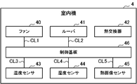
- the indoor unit 4 includes a fan 40, a louver 41, a heat exchanger 42, a temperature sensor 43, a humidity sensor 44, a thermal image sensor 45, and a control board 46.
- the fan 40 is, for example, a sirocco fan, takes in the air in the room R from a suction port (not shown) of the indoor unit 4, and sends out the air that has been heat-exchanged by the heat exchanger 42 from a blowout port (not shown) of the indoor unit 4. ..
- the fan 40 is communicatively connected to the control board 46 via a communication line CL1.
- the rotation speed of the fan 40 that is, the amount of air blown by the fan 40 is adjusted according to a control command from the control board 46.
- the louver 41 adjusts the direction of the air sent to the room R by the fan 40.
- the louver 41 is communicatively connected to the control board 46 via a communication line CL2.
- the angle of the louver 41, that is, the wind direction is adjusted according to a control command from the control board 46.
- the heat exchanger 42 exchanges heat between the air taken in by the fan 40 and the refrigerant from the outdoor unit 5.
- the heat exchanger 42 functions as an evaporator during cooling operation, and functions as a condenser during heating operation.
- the temperature sensor 43 measures the temperature of the air taken in by the fan 40.
- the temperature sensor 43 is communicatively connected to the control board 46 via the communication line CL3.
- the temperature sensor 43 transmits data indicating the measured temperature (hereinafter, referred to as temperature data) to the control board 46.
- the humidity sensor 44 measures the humidity of the air taken in by the fan 40.
- the humidity sensor 44 is communicatively connected to the control board 46 via the communication line CL4.
- the humidity sensor 44 transmits data indicating the measured humidity (hereinafter, referred to as humidity data) to the control board 46 in response to a request from the control board 46.
- the thermal image sensor 45 is an example of the thermal image sensor according to the present invention.
- the thermal image sensor 45 is infrared thermography and acquires a thermal image of the room R.
- the thermal image sensor 45 is communicatively connected to the control board 46 via a communication line CL5.
- the thermal image sensor 45 transmits data indicating the acquired thermal image (hereinafter referred to as thermal image data) to the control board 46.
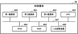
- the control board 46 includes a first communication unit 460, a second communication unit 461, a third communication unit 462, a CPU 463, a ROM 464, a RAM 465, and a secondary storage device 466. .. These components are connected to each other via a bus 467.
- the first communication unit 460 is hardware that communicates with the outdoor unit 5 via the communication line 7.
- the second communication unit 461 is hardware that performs wireless communication such as infrared communication with the air conditioning remote controller 6.
- the third communication unit 462 is hardware that performs wireless communication with the biological data measuring device 3 in accordance with communication standards such as Wi-Fi (registered trademark) and BLE (Bluetooth Low Energy; Bluetooth is a registered trademark).
- a CPU (Central Processing Unit) 463 centrally controls the air conditioner 2. That is, like the general indoor unit, the fan 40 and the louver 41 are controlled to perform the air conditioning according to the contents operated by the user via the air conditioning remote controller 6, and the operation of the outdoor unit 5 is controlled. Further, the CPU 463 also performs air conditioning control according to the thermal sensation of the user in the room R. Details of the function peculiar to the control board 46 realized by the CPU 463 will be described later.
- a ROM (Read Only Memory) 464 stores a plurality of firmware and data used when these firmwares are executed.
- a RAM (Random Access Memory) 465 is used as a work area of the CPU 463.
- the secondary storage device 466 is composed of a readable/writable nonvolatile semiconductor memory such as an EEPROM (Electrically Erasable Programmable Read-Only Memory) and a flash memory.
- the secondary storage device 466 stores an air conditioning control program for executing the air conditioning control and data used when the air conditioning control program is executed.
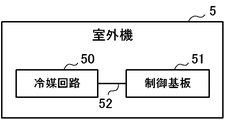
- the outdoor unit 5 includes a refrigerant circuit 50 and a control board 51, as shown in FIG.
- the refrigerant circuit 50 and the control board 51 are communicatively connected via a communication line 52.
- the refrigerant circuit 50 includes a compressor, a condenser, an expansion valve, an evaporator, and the like.
- the control board 51 is communicably connected to the indoor unit 4 via the communication line 7.
- the control board 51 is configured to include a CPU, a ROM, a RAM, a communication interface, a readable/writable nonvolatile semiconductor memory, etc. (none of which is shown).
- the control board 51 controls the operation of the refrigerant circuit 50, more specifically, the drive of the compressor, based on the control command received from the control board 46 of the indoor unit 4.
- the air conditioning remote controller 6 is a remote controller that is installed so as to be embedded in the wall of the room R or installed in a manner hung on the wall to accept operations related to air conditioning from a user who uses the room R.
- the user operates the air conditioning remote controller 6 to instruct to start or stop the operation, change the operation mode such as cooling, heating, dehumidification, and air blowing, and change the set temperature, set humidity, air blowing amount, air direction, and the like. It is also possible to set the timer.
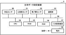
- the biometric data measuring device 3 is an example of the biometric data measuring device according to the present invention.
- the biometric data measuring device 3 is a human-body-mounted (for example, wristband type) device that measures biometric data of a user who uses the room R.
- the biological data includes body temperature, heart rate, sweat rate, and the like.
- the biological data measuring device 3 includes a body temperature sensor 30, a heart rate sensor 31, a sweat rate sensor 32, a communication unit 33, a CPU 34, a ROM 35, a RAM 36, and a secondary storage device 37. With. These components are connected to each other via a bus 38. Further, the biological data measuring device 3 includes a battery 39 such as a primary battery or a secondary battery that supplies electric power to each component.
- the body temperature sensor 30 measures the body temperature of the user wearing the biological data measuring device 3.
- the heart rate sensor 31 measures the heart rate of the user.
- the sweat rate sensor 32 measures the sweat rate of the user.
- the communication unit 33 is hardware that wirelessly communicates with the indoor unit 4.
- the CPU 34 controls the biological data measuring device 3 in a centralized manner.
- the ROM 35 stores a plurality of firmware and data used when these firmwares are executed.
- the RAM 36 is used as a work area of the CPU 34.
- the secondary storage device 37 is composed of a readable/writable nonvolatile semiconductor memory such as an EEPROM or a flash memory. Although not shown, the secondary storage device 37 stores a program for measuring biometric data, a program for communicating with the indoor unit 4, and data used when these programs are executed.
- the CPU 34 stores data (hereinafter, referred to as measurement data) in which the biometric data (that is, body temperature, heart rate, and sweat rate) measured by the body temperature sensor 30, the heart rate sensor 31, and the sweat rate sensor 32 are stored.
- the data is wirelessly transmitted to the indoor unit 4 via the communication unit 33 at regular time intervals (for example, one minute intervals).
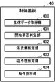
- control board 46 is functionally provided with a biometric data acquisition section 400, a start necessity determination section 401, a clothing amount estimation section 402, a thermal sensation estimation section 403, and an operation command section. And 404.
- These functional units are realized by the CPU 463 executing the above-described air conditioning control program stored in the secondary storage device 466.
- the biometric data acquisition unit 400 is an example of biometric data acquisition means according to the present invention.
- the biometric data acquisition unit 400 receives the above-described measurement data sent from the biometric data measuring device 3 periodically (for example, every one minute).
- the biometric data acquisition unit 400 extracts and acquires each biometric data (that is, body temperature, heart rate, and sweat rate) from the received measurement data.
- the biometric data acquisition unit 400 stores the acquired biometric data in a biometric data table (not shown) stored in the RAM 465 or the secondary storage device 466 in association with the time when the biometric data is acquired (that is, the time when the measurement data is received). ..
- the start necessity determination unit 401 determines whether or not it is necessary to start the air conditioning control (hereinafter referred to as comfort control) according to the user's thermal sensation so that the user feels comfortable. For example, the start necessity determination unit 401 determines that it is necessary to start comfort control when the elapsed time after the user enters the room R reaches a predetermined reference time. This is for avoiding execution of comfort control when the user's thermal sensation is unstable. The start necessity determination unit 401 may determine that the comfort control needs to be started when the heart rate of the user who has entered the room R has settled at a normal value.
- Whether or not the user has entered the room R can be determined from the communication status with the biological data measuring device 3 or the thermal image in the room R. That is, the start necessity determination unit 401 may determine that the user has entered the room R when the communication with the biological data measuring device 3 is started, or the person is reflected in the thermal image in the room R. If so, it may be determined that the user has entered the room R.
- the clothing amount estimation unit 402 estimates the clothing amount of the user who is in the room R.
- the clothing amount estimation unit 402 analyzes the thermal image acquired by the thermal image sensor 45 by a well-known method to estimate the surface temperature of the user's clothing portion (hereinafter referred to as clothing surface temperature).
- the clothing amount estimation unit 402 also acquires the latest body temperature of the user from the biometric data table. Then, the clothing amount estimation unit 402 estimates the clothing amount of the user according to the difference between the acquired body temperature of the user and the estimated clothing surface temperature.
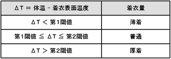
- the clothing amount estimation unit 402 when the difference ( ⁇ T) between the body temperature and the clothing surface temperature is smaller than a predetermined first threshold value, the clothing amount estimation unit 402 has a small amount of clothing for the user, That is, it is presumed that it is light clothing. If ⁇ T is equal to or larger than the first threshold and equal to or smaller than the second threshold set in advance, the clothing amount estimation unit 402 estimates that the clothing amount of the user is normal. When ⁇ T is larger than the second threshold, the clothing amount estimation unit 402 estimates that the clothing amount of the user is heavy clothing.
- the thermal sensation estimation unit 403 estimates the user's sense of the current thermal environment, that is, thermal sensation, based on the clothing amount of the user estimated by the clothing amount estimation unit 402. Specifically, when the user wears heavy clothing, the thermal sensation estimation unit 403 estimates that the user feels cold. Further, when the user wears light clothing, the thermal sensation estimation unit 403 estimates that the user feels hot. When the amount of clothing of the user is normal, the thermal sensation estimation unit 403 estimates that the user feels neither hot nor cold (that is, comfortable).
- the operation command unit 404 determines the content of the air conditioning control based on the user's thermal sensation estimated by the thermal sensation estimation unit 403, and the fan 40, the louver 41, and the outdoor unit 5 according to the determined content of the air conditioning control.
- the control command for each is generated and transmitted to each.
- the operation command unit 404 generates a control command for intensifying heating to each of the fan 40, the louver 41, and the outdoor unit 5 when the user feels cold during heating operation.
- a control command for increasing the set temperature (also referred to as a target temperature) by 1 to 3° C. or increasing the air flow rate is generated.
- the operation command unit 404 generates a control command for weakening the heating to each of the fan 40, the louver 41, and the outdoor unit 5 when the user feels hot during the heating operation.
- a control command for lowering the set temperature by 1 to 3° C. or reducing the air flow is generated.
- the operation command unit 404 generates a control command for strengthening the cooling to each of the fan 40, the louver 41, and the outdoor unit 5 when the user feels hot during the cooling operation.
- a control command for lowering the set temperature by 1 to 3° C. or increasing the blown air volume is generated.
- the operation command unit 404 generates a control command for weakening the cooling to each of the fan 40, the louver 41, and the outdoor unit 5 when the user feels cold during the cooling operation.
- a control command for increasing the set temperature by 1 to 3° C. or reducing the air flow is generated.
- the start necessity determination unit 401, the clothing amount estimation unit 402, the thermal sensation estimation unit 403, and the operation command unit 404 are examples of the air conditioning control unit according to the present invention.
- FIG. 8 is a flowchart showing the procedure of the air conditioning control process executed by the control board 46 of the indoor unit 4.
- the air conditioning control process is started when the user enters the room R.
- the clothing amount estimation unit 402 estimates the clothing amount of the user in the room R (step S102).
- the thermal sensation estimation unit 403 estimates the current thermal sensation of the user based on the clothing amount of the user estimated by the clothing amount estimation unit 402 (step S103).
- the operation command unit 404 determines the content of the air conditioning control based on the user's thermal sensation estimated by the thermal sensation estimation unit 403 (step S104).
- the operation command unit 404 generates a control command for each of the fan 40, the louver 41, and the outdoor unit 5 based on the determined content of the air conditioning control (step S105). Then, the operation command unit 404 transmits each generated control command to each of the fan 40, the louver 41, and the outdoor unit 5 (step S106).
- step S108 the CPU 463 of the control board 46 determines whether or not the user has exited the room R (step S108). ). Whether or not the user has left the room R can be determined from the communication status with the biological data measuring device 3 or the thermal image in the room R. That is, the CPU 463 may determine that the user has exited the room when communication with the biological data measuring device 3 is not possible, and when the person in the thermal image in the room R is not included in the room R, the user exits the room. You may judge that it has been completed.
- a predetermined waiting time for example, 10 minutes
- step S108 If the user has already left the room (step S108; YES), the CPU 463 ends the air conditioning control process. On the other hand, if the user has not left the room (step S108; NO), the process returns to step S102.
- the thermal sensation of the user is estimated and estimated based on the thermal image of the room R and the biometric data of the user who has entered the room R.
- the room R is air-conditioned according to the sense of heat and cold. This makes it possible to accurately realize comfortable air conditioning for the user in the room R.
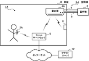
- FIG. 9 is a diagram showing an overall configuration of an air conditioning system 1A according to the second embodiment of the present invention.
- the air conditioning system 1A is a system for air conditioning the room R in the building, and as shown in FIG. 9, includes an air conditioner 2A, a biometric data measuring device 3A, a home gateway 9, and a cloud server 10.
- the air conditioner 2A is an example of the air conditioner according to the present invention.
- the air conditioner 2A includes an indoor unit 4A installed in the room R, an outdoor unit 5 installed outside the room R, and an air conditioning remote controller 6 installed in the room R.
- the indoor unit 4A and the outdoor unit 5 are connected via a communication line 7 and a refrigerant pipe 8 for circulating a refrigerant.
- the hardware configuration of the indoor unit 4A is the same as that of the indoor unit 4 of the first embodiment (see FIGS. 2 and 3). However, the third communication unit 462 of the control board 46 included in the indoor unit 4A communicates with the cloud server 10 connected to the Internet via the home gateway 9 having a function as a broadband router.
- the CPU 463 of the control board 46 included in the indoor unit 4A does not perform the air conditioning control according to the thermal sensation of the user in the room R as in the first embodiment, and instead, the heat acquired by the thermal image sensor 45 is used.
- Air conditioning information that stores the image, the current operating state (for example, operating or stopped, operating mode, set temperature, set humidity, etc.) and the current air state (room temperature, humidity, etc.) of the room R is fixed.
- the data is transmitted to the cloud server 10 at time intervals (for example, 1 minute intervals).
- the CPU 463 of the indoor unit 4A also performs air conditioning control according to control data from the cloud server 10 in addition to air conditioning control according to a user operation via the air conditioning remote controller 6.
- the hardware configuration of the biometric data measuring device 3A is the same as that of the biometric data measuring device 3 of the first embodiment (see FIG. 5). However, the communication unit 33 of the biometric data measuring device 3A communicates with the cloud server 10 via the home gateway 9.
- the CPU 34 of the biometric data measuring device 3A keeps constant the measurement data in which the biometric data (that is, the body temperature, the heart rate, and the sweat rate) measured by the body temperature sensor 30, the heart rate sensor 31, and the sweat rate sensor 32 are stored.
- the data is transmitted to the cloud server 10 at time intervals (for example, 1 minute intervals).
- the cloud server 10 is an example of the control device according to the present invention.
- the cloud server 10 is a server computer installed and operated by a manufacturer of the air conditioner 2A, a sales company, etc., and is connected to the Internet.
- the cloud server 10 includes a communication unit 11, a CPU 12, a ROM 13, a RAM 14, and a secondary storage device 15. These components are connected to each other via a bus 16.
- the communication unit 11 is hardware for connecting to the Internet and communicating with the indoor unit 4A and the biological data measuring device 3A via the home gateway 9.
- the CPU 12 centrally controls the cloud server 10. Details of the functions of the cloud server 10 realized by the CPU 12 will be described later.
- the ROM 13 stores a plurality of firmware and data used when these firmwares are executed.
- the RAM 14 is used as a work area of the CPU 12.
- the secondary storage device 15 is a large-capacity storage device configured to include a readable/writable non-volatile semiconductor memory such as an EEPROM or a flash memory, or an HDD (Hard Disk Drive).
- the secondary storage device 15 stores an air conditioning control program for executing the air conditioning control and data used when the air conditioning control program is executed.
- the cloud server 10 functionally has an air conditioning information acquisition unit 100, a biometric data acquisition unit 101, a start necessity determination unit 102, a clothing amount estimation unit 103, and a thermal sensation estimation.
- the unit 104 and the operation command unit 105 are provided. These functional units are realized by the CPU 12 executing the above-described air conditioning control program stored in the secondary storage device 15.
- the air conditioning information acquisition unit 100 is an example of an air conditioning information acquisition unit according to the present invention.
- the air-conditioning information acquisition unit 100 receives and acquires the above-mentioned air-conditioning information sent from the indoor unit 4A periodically (for example, every minute).
- the air conditioning information acquisition unit 100 stores the received air conditioning information in an air conditioning information table (not shown) stored in the secondary storage device 15 in association with the time of reception.
- the biometric data acquisition unit 101 is an example of biometric data acquisition means according to the present invention.
- the biometric data acquisition unit 101 receives the above-described measurement data sent from the biometric data measuring device 3A periodically (for example, every one minute).
- the biometric data acquisition unit 101 extracts and acquires each biometric data (that is, body temperature, heart rate, and sweat rate) from the received measurement data.
- the biometric data acquisition unit 101 stores the acquired biometric data in a biometric data table (not shown) stored in the secondary storage device 15 in association with the time when the biometric data was acquired (that is, the time when the measurement data was received).
- the start necessity determination unit 102 determines whether or not it is necessary to start comfort control by the same method as the start necessity determination unit 401 of the first embodiment.
- the clothing amount estimation unit 103 estimates the amount of clothing of the user who is in the room R in the same manner as the clothing amount estimation unit 402 of the first embodiment.
- the thermal sensation estimation unit 104 estimates the current thermal sensation of the user by the same method as the thermal sensation estimation unit 403 of the first embodiment.
- the operation command unit 105 determines the content of the air conditioning control by the same method as the operation command unit 404 of the first embodiment.
- the operation command unit 105 generates control data based on the determined content of the air conditioning control, and transmits the control data to the indoor unit 4A of the air conditioner 2A.
- the indoor unit 4A that has received the control data executes the air conditioning control indicated by the control data.
- the start necessity determination unit 102, the clothing amount estimation unit 103, the thermal sensation estimation unit 104, and the operation command unit 105 are an example of an air conditioning control unit according to the present invention.
- the cloud server 10 determines the thermal sensation of the user based on the thermal image of the room R and the biometric data of the user in the room R.
- the air conditioning of the room R is performed by controlling the air conditioner 2A according to the estimated thermal sensation. This makes it possible to accurately realize comfortable air conditioning for the user.
- the biometric data measuring device 3A may be replaced with the biometric data measuring device 3.
- the biological data measuring device 3 transmits the measurement data to the indoor unit 4A
- the indoor unit 4A transmits the measurement data received from the biological data measuring device 3 to the cloud server 10.
- the amount of clothing in each of the above-mentioned embodiments, three levels of indicators of light wear, normal wear, and heavy wear are shown, but the degree of light wear and heavy wear may be indicated in multiple levels. Alternatively, the amount of clothing may be indicated by a numerical value.
- the threshold value (for example, the above-mentioned first threshold value and second threshold value) that is compared with the difference ( ⁇ T) between the body temperature and the clothing surface temperature may be changed according to the season.
- the estimated user's thermal sensation is not limited to “hot”, “comfortable”, or “cold”, and may be “slightly hot”, “very hot”, “slightly cold”, “very cold”, etc. , May be estimated in more detail.
- the indoor unit 4 or the cloud server 10 may estimate the activity amount of the user who has entered the room R and may determine the content of the air conditioning control in consideration of the estimated activity amount.
- the amount of user activity is estimated by the heart rate and/or the amount of sweat.
- the indoor unit 4 or the cloud server 10 may estimate the amount of activity by calculating the amount of movement of the user from the thermal image.
- the reference time used when determining whether or not the comfort control needs to be started, the degree of air conditioning strength according to the user's thermal sensation, etc. are appropriately updated by learning based on the operation of the air conditioning remote controller 6 by the user. It may be done.
- biometric data measuring devices 3 and 3A may be configured to further include other sensors for measuring biometric data, or may be configured to include only the body temperature sensor 30.
- the biometric data measuring devices 3 and 3A may be configured by one or a plurality of sensors that measure biometric data and a data collecting device that is connected to each sensor in a wired or wireless manner. In this case, each sensor is attached to an appropriate place on the user's body.
- control board 46 of the indoor units 4 and 4A may be realized by the control board 51 of the outdoor unit 5.
- a control device having the same function as the cloud server 10 may be installed in the building having the room R.
- the air conditioning control program stored in the secondary storage device 15 is executed by the CPU 12 of the CPU cloud server 10 to realize the functional unit of the cloud server 10 (see FIG. 11 ). Was done.
- the dedicated hardware is, for example, a single circuit, a composite circuit, a programmed processor, an ASIC (Application Specific Integrated Circuit), an FPGA (Field-Programmable Gate Array), or a combination thereof.
- ASIC Application Specific Integrated Circuit
- FPGA Field-Programmable Gate Array
- the above-mentioned air conditioning control program is used for CD-ROM (Compact Disc Read Only Memory), DVD (Digital Versatile Disc), magneto-optical disc (Magneto-Optical Disc), USB (Universal Serial Bus) memory, memory card, HDD, etc. It is also possible to store it in a computer-readable recording medium and distribute it. Then, by installing the air conditioning control program on a specific or general-purpose computer, it is possible to cause the computer to function as the cloud server 10 in the second embodiment.
- CD-ROM Compact Disc Read Only Memory
- DVD Digital Versatile Disc
- magneto-optical disc Magneto-optical disc
- USB Universal Serial Bus
- the air conditioning control program may be stored in a storage device included in a server (not shown) on the Internet, and the air conditioning control program may be downloaded from the server to the cloud server 10.
- the present invention can be suitably applied to a system for air conditioning in a building.
Landscapes
- Engineering & Computer Science (AREA)
- Chemical & Material Sciences (AREA)
- Combustion & Propulsion (AREA)
- Mechanical Engineering (AREA)
- General Engineering & Computer Science (AREA)
- Air Conditioning Control Device (AREA)
Abstract
L'invention concerne un climatiseur comprenant une unité intérieure (4) qui comprend un capteur d'image thermique (45) qui acquiert une image thermique intérieure et une carte de commande (46) qui commande la climatisation. La carte de commande (46) acquiert des données biologiques mesurées à partir d'un dispositif de mesure de données biologiques porté par un utilisateur. Les données biologiques mesurées par le dispositif de mesure de données biologiques comprennent au moins la température corporelle de l'utilisateur. La carte de commande (46) effectue une commande de climatisation sur la base de l'image thermique acquise par le capteur d'image thermique (45) et des données biologiques acquises à partir du dispositif de mesure de données biologiques.
Priority Applications (2)
| Application Number | Priority Date | Filing Date | Title |
|---|---|---|---|
| JP2020558807A JP7086219B2 (ja) | 2018-12-10 | 2018-12-10 | 空調機、制御装置、空調システム、空調制御方法及びプログラム |
| PCT/JP2018/045275 WO2020121370A1 (fr) | 2018-12-10 | 2018-12-10 | Climatiseur, dispositif de commande, système de climatisation, procédé de commande de climatisation et programme |
Applications Claiming Priority (1)
| Application Number | Priority Date | Filing Date | Title |
|---|---|---|---|
| PCT/JP2018/045275 WO2020121370A1 (fr) | 2018-12-10 | 2018-12-10 | Climatiseur, dispositif de commande, système de climatisation, procédé de commande de climatisation et programme |
Publications (1)
| Publication Number | Publication Date |
|---|---|
| WO2020121370A1 true WO2020121370A1 (fr) | 2020-06-18 |
Family
ID=71077228
Family Applications (1)
| Application Number | Title | Priority Date | Filing Date |
|---|---|---|---|
| PCT/JP2018/045275 Ceased WO2020121370A1 (fr) | 2018-12-10 | 2018-12-10 | Climatiseur, dispositif de commande, système de climatisation, procédé de commande de climatisation et programme |
Country Status (2)
| Country | Link |
|---|---|
| JP (1) | JP7086219B2 (fr) |
| WO (1) | WO2020121370A1 (fr) |
Cited By (5)
| Publication number | Priority date | Publication date | Assignee | Title |
|---|---|---|---|---|
| WO2020230895A1 (fr) * | 2019-05-15 | 2020-11-19 | ダイキン工業株式会社 | Système d'estimation du confort thermique |
| JP2020189081A (ja) * | 2019-05-15 | 2020-11-26 | ダイキン工業株式会社 | 温熱快適性を推定するためのシステム |
| CN113482962A (zh) * | 2021-08-06 | 2021-10-08 | 中山市技佳传动科技有限公司 | 一种基于风扇温度自适应控制系统和方法 |
| JPWO2023276735A1 (fr) * | 2021-06-30 | 2023-01-05 | ||
| EP4224081A4 (fr) * | 2020-11-04 | 2024-08-21 | Daikin Industries, Ltd. | Dispositif et procédé de gestion de charge de température et programme informatique |
Families Citing this family (1)
| Publication number | Priority date | Publication date | Assignee | Title |
|---|---|---|---|---|
| KR102924218B1 (ko) * | 2023-04-12 | 2026-02-10 | 한국과학기술원 | 열적 쾌적감 개선과 빌딩 에너지 효율 증대를 위한 지능형 웨어러블 열쾌적성 예측 플랫폼 기반 인간중심 공기조화 제어 시스템 및 그의 동작 방법 |
Citations (9)
| Publication number | Priority date | Publication date | Assignee | Title |
|---|---|---|---|---|
| JPH06117836A (ja) * | 1992-08-21 | 1994-04-28 | Matsushita Electric Ind Co Ltd | 画像処理装置と空気調和機の制御装置と画像処理装置を用いた応用機器 |
| JP2008241135A (ja) * | 2007-03-27 | 2008-10-09 | Toshiba Corp | 温冷感判定装置及び方法、及び前記温冷感判定結果を用いた空調制御装置及び方法 |
| WO2013145544A1 (fr) * | 2012-03-29 | 2013-10-03 | パナソニック株式会社 | Dispositif de commande d'appareil, système de commande d'appareil et programme |
| WO2013145541A1 (fr) * | 2012-03-29 | 2013-10-03 | パナソニック株式会社 | Dispositif de commande d'appareil, système de commande d'appareil et programme |
| WO2015122201A1 (fr) * | 2014-02-17 | 2015-08-20 | パナソニック株式会社 | Climatiseur et système de capteur d'image thermique |
| JP2016065848A (ja) * | 2014-03-03 | 2016-04-28 | パナソニック インテレクチュアル プロパティ コーポレーション オブ アメリカPanasonic Intellectual Property Corporation of America | センシング方法、センシングシステムおよびそれらを備える空調機器 |
| JP2018077256A (ja) * | 2013-05-17 | 2018-05-17 | パナソニック インテレクチュアル プロパティ コーポレーション オブ アメリカPanasonic Intellectual Property Corporation of America | 熱画像センサ、及び、ユーザインターフェース |
| JP2018524538A (ja) * | 2015-06-12 | 2018-08-30 | ユニバーシティー オブ メリーランド,カレッジ パーク | コンフォートユニット及びシステム、それらを用いる方法及び装置 |
| JP2018185083A (ja) * | 2017-04-25 | 2018-11-22 | 三菱電機株式会社 | 環境制御システムおよび環境制御方法 |
Family Cites Families (3)
| Publication number | Priority date | Publication date | Assignee | Title |
|---|---|---|---|---|
| JP2008232467A (ja) | 2007-03-16 | 2008-10-02 | Toshiba Corp | 空調制御システム |
| JP2018091573A (ja) | 2016-12-06 | 2018-06-14 | アイシン精機株式会社 | 空調機器制御装置 |
| JP6967730B2 (ja) | 2018-09-27 | 2021-11-17 | パナソニックIpマネジメント株式会社 | 空気調和システムおよび空気調和方法 |
-
2018
- 2018-12-10 WO PCT/JP2018/045275 patent/WO2020121370A1/fr not_active Ceased
- 2018-12-10 JP JP2020558807A patent/JP7086219B2/ja active Active
Patent Citations (9)
| Publication number | Priority date | Publication date | Assignee | Title |
|---|---|---|---|---|
| JPH06117836A (ja) * | 1992-08-21 | 1994-04-28 | Matsushita Electric Ind Co Ltd | 画像処理装置と空気調和機の制御装置と画像処理装置を用いた応用機器 |
| JP2008241135A (ja) * | 2007-03-27 | 2008-10-09 | Toshiba Corp | 温冷感判定装置及び方法、及び前記温冷感判定結果を用いた空調制御装置及び方法 |
| WO2013145544A1 (fr) * | 2012-03-29 | 2013-10-03 | パナソニック株式会社 | Dispositif de commande d'appareil, système de commande d'appareil et programme |
| WO2013145541A1 (fr) * | 2012-03-29 | 2013-10-03 | パナソニック株式会社 | Dispositif de commande d'appareil, système de commande d'appareil et programme |
| JP2018077256A (ja) * | 2013-05-17 | 2018-05-17 | パナソニック インテレクチュアル プロパティ コーポレーション オブ アメリカPanasonic Intellectual Property Corporation of America | 熱画像センサ、及び、ユーザインターフェース |
| WO2015122201A1 (fr) * | 2014-02-17 | 2015-08-20 | パナソニック株式会社 | Climatiseur et système de capteur d'image thermique |
| JP2016065848A (ja) * | 2014-03-03 | 2016-04-28 | パナソニック インテレクチュアル プロパティ コーポレーション オブ アメリカPanasonic Intellectual Property Corporation of America | センシング方法、センシングシステムおよびそれらを備える空調機器 |
| JP2018524538A (ja) * | 2015-06-12 | 2018-08-30 | ユニバーシティー オブ メリーランド,カレッジ パーク | コンフォートユニット及びシステム、それらを用いる方法及び装置 |
| JP2018185083A (ja) * | 2017-04-25 | 2018-11-22 | 三菱電機株式会社 | 環境制御システムおよび環境制御方法 |
Cited By (6)
| Publication number | Priority date | Publication date | Assignee | Title |
|---|---|---|---|---|
| WO2020230895A1 (fr) * | 2019-05-15 | 2020-11-19 | ダイキン工業株式会社 | Système d'estimation du confort thermique |
| JP2020189081A (ja) * | 2019-05-15 | 2020-11-26 | ダイキン工業株式会社 | 温熱快適性を推定するためのシステム |
| EP4224081A4 (fr) * | 2020-11-04 | 2024-08-21 | Daikin Industries, Ltd. | Dispositif et procédé de gestion de charge de température et programme informatique |
| JPWO2023276735A1 (fr) * | 2021-06-30 | 2023-01-05 | ||
| JP7627882B2 (ja) | 2021-06-30 | 2025-02-07 | パナソニックIpマネジメント株式会社 | 気流制御システム、及び、気流制御方法 |
| CN113482962A (zh) * | 2021-08-06 | 2021-10-08 | 中山市技佳传动科技有限公司 | 一种基于风扇温度自适应控制系统和方法 |
Also Published As
| Publication number | Publication date |
|---|---|
| JPWO2020121370A1 (ja) | 2021-06-03 |
| JP7086219B2 (ja) | 2022-06-17 |
Similar Documents
| Publication | Publication Date | Title |
|---|---|---|
| JP7086219B2 (ja) | 空調機、制御装置、空調システム、空調制御方法及びプログラム | |
| JP6334299B2 (ja) | 空調制御装置、空調制御方法、及びプログラム | |
| JP7408976B2 (ja) | 空気調和機 | |
| JP6685418B2 (ja) | 空調システム、空調制御装置、空調方法及びプログラム | |
| WO2021199381A1 (fr) | Système de climatisation et procédé de commande de climatiseur | |
| JP7283157B2 (ja) | 空調制御装置 | |
| CN103075784A (zh) | 表面温度推定装置、表面温度推定方法以及结露判定装置 | |
| JP2016173198A (ja) | 空気調和機および空気調和機の制御方法 | |
| JP7321283B2 (ja) | 制御装置、空気調和装置および空気調和システム | |
| JP7475557B2 (ja) | 空気調和システム、情報処理装置および空調機器の制御方法 | |
| JP6280456B2 (ja) | 空調システムおよび空調制御方法 | |
| JP6701449B1 (ja) | 空調装置、制御装置、空調方法及びプログラム | |
| JP6698947B1 (ja) | 空調装置、制御装置、空調方法及びプログラム | |
| JP2014020650A (ja) | 湿度推定装置及び空調システム | |
| KR20120083140A (ko) | 공기조화시스템 및 그 제어방법 | |
| WO2017159632A1 (fr) | Climatiseur | |
| JP7479551B2 (ja) | 空調機、空調制御方法、及び、プログラム | |
| JP6920991B2 (ja) | コントローラ、機器制御方法、及び、プログラム | |
| JP4022537B2 (ja) | 空調システム | |
| US20260085850A1 (en) | Air-conditioning system, control method, and recording medium | |
| JP7357673B2 (ja) | 制御装置、空気環境調整システム、空気環境調整方法、プログラム、及び記録媒体 | |
| WO2012144625A1 (fr) | Système de commande de climatisation | |
| JP5284528B2 (ja) | 空調制御装置、空調システム、空調制御方法、空調制御用プログラム | |
| JP2021188811A (ja) | 空調システム、空調装置、及び、空調制御方法 | |
| JP7550611B2 (ja) | 空調制御装置、空調システム、換気促進方法及びプログラム |
Legal Events
| Date | Code | Title | Description |
|---|---|---|---|
| 121 | Ep: the epo has been informed by wipo that ep was designated in this application |
Ref document number: 18942714 Country of ref document: EP Kind code of ref document: A1 |
|
| ENP | Entry into the national phase |
Ref document number: 2020558807 Country of ref document: JP Kind code of ref document: A |
|
| NENP | Non-entry into the national phase |
Ref country code: DE |
|
| 122 | Ep: pct application non-entry in european phase |
Ref document number: 18942714 Country of ref document: EP Kind code of ref document: A1 |