WO2020121401A1 - Carpule, système de pince, et procédé de mise en prise - Google Patents
Carpule, système de pince, et procédé de mise en prise Download PDFInfo
- Publication number
- WO2020121401A1 WO2020121401A1 PCT/JP2018/045453 JP2018045453W WO2020121401A1 WO 2020121401 A1 WO2020121401 A1 WO 2020121401A1 JP 2018045453 W JP2018045453 W JP 2018045453W WO 2020121401 A1 WO2020121401 A1 WO 2020121401A1
- Authority
- WO
- WIPO (PCT)
- Prior art keywords
- sheath
- housing
- pusher
- engagement member
- insertion hole
- Prior art date
- Legal status (The legal status is an assumption and is not a legal conclusion. Google has not performed a legal analysis and makes no representation as to the accuracy of the status listed.)
- Ceased
Links
Images







Classifications
-
- A—HUMAN NECESSITIES
- A61—MEDICAL OR VETERINARY SCIENCE; HYGIENE
- A61B—DIAGNOSIS; SURGERY; IDENTIFICATION
- A61B17/00—Surgical instruments, devices or methods
- A61B17/12—Surgical instruments, devices or methods for ligaturing or otherwise compressing tubular parts of the body, e.g. blood vessels or umbilical cord
- A61B17/122—Clamps or clips, e.g. for the umbilical cord
- A61B17/1227—Spring clips
-
- A—HUMAN NECESSITIES
- A61—MEDICAL OR VETERINARY SCIENCE; HYGIENE
- A61B—DIAGNOSIS; SURGERY; IDENTIFICATION
- A61B17/00—Surgical instruments, devices or methods
- A61B17/12—Surgical instruments, devices or methods for ligaturing or otherwise compressing tubular parts of the body, e.g. blood vessels or umbilical cord
- A61B17/128—Surgical instruments, devices or methods for ligaturing or otherwise compressing tubular parts of the body, e.g. blood vessels or umbilical cord for applying or removing clamps or clips
- A61B17/1285—Surgical instruments, devices or methods for ligaturing or otherwise compressing tubular parts of the body, e.g. blood vessels or umbilical cord for applying or removing clamps or clips for minimally invasive surgery
-
- A—HUMAN NECESSITIES
- A61—MEDICAL OR VETERINARY SCIENCE; HYGIENE
- A61B—DIAGNOSIS; SURGERY; IDENTIFICATION
- A61B17/00—Surgical instruments, devices or methods
- A61B17/12—Surgical instruments, devices or methods for ligaturing or otherwise compressing tubular parts of the body, e.g. blood vessels or umbilical cord
- A61B17/122—Clamps or clips, e.g. for the umbilical cord
- A61B17/1222—Packages or dispensers therefor
-
- A—HUMAN NECESSITIES
- A61—MEDICAL OR VETERINARY SCIENCE; HYGIENE
- A61B—DIAGNOSIS; SURGERY; IDENTIFICATION
- A61B17/00—Surgical instruments, devices or methods
- A61B2017/00367—Details of actuation of instruments, e.g. relations between pushing buttons, or the like, and activation of the tool, working tip, or the like
Definitions
- the present invention relates to a clip cartridge, a clip system, and an engaging method for ligating body tissue.
- a clip device which ligates a tissue to be treated with a clip in order to close an opening generated in a living tissue or perform a hemostasis treatment.
- the clip device includes an operating portion, a sheath, and an operating wire that is in communication with the sheath and is connected to the operating portion.
- the sheath is inserted into the channel of the endoscope, and is inserted into the body via the channel.
- Patent Document 1 discloses a clip device in which a pair of jaws is rotatably supported by a housing.
- the driver to which the heads of the drive wires are connected and the base ends of the pair of jaws are connected by a rack-pinion structure, and the pair of jaws rotate with respect to the housing as the drive wires advance and retract. Open and close.
- the clip device that holds the clip inside the body is inserted into the body with the clip connected to the tip of the sheath.
- the arm of the clip (a pair of jaws) is opened by operating the drive wire to bring it into contact with the tissue, and then the clip is closed to ligate the tissue. After that, the clip is disconnected from the drive wire and the clip is placed in the body. Therefore, before placing the clip in the body, the clip and the tip of the endoscope channel are connected, and after placing the clip, it is necessary to release the connection between the clip and the tip of the endoscope channel. is there.
- connection block is provided in the tubular connector, the connection block is projected from the tubular connector by the operation of the drive wire and press-fitted into the housing, and the housing and the tubular connector are connected via the connection block. It is fixed.
- a flexible wire is preferable as the drive force transmission wire in consideration of insertability of the treatment tool.
- the frictional force between the connection block and the housing is larger than the pushing force of the drive wire.
- the connection block cannot be pressed into the housing, so that the housing and the tubular connector cannot be fixed.
- the housing and the tubular connector cannot be fixed, because the connection block can be pushed back into the tubular connector.
- the tissue to be treated may be ligated continuously with a clip.
- the entire clip device is replaced with the next clip device to which the clip is attached in advance, and the tissue to be treated is ligated with the clip.
- the present invention has been made in view of the above-mentioned circumstances, and an object of the present invention is to provide a cartridge, a clip system, and a clip engaging method by which a clip can be easily reloaded in an applicator.
- a cartridge according to a first aspect of the present invention accommodates a clip unit including an arm member and a tubular housing into which the arm member is inserted, and is capable of engaging with the housing and the arm member.
- a cartridge configured such that the clip unit can be attached to an applicator having a different operation wire, the main body having an insertion hole into which the sheath is inserted, and a pusher movable with respect to the main body, The pusher can be brought into contact with an engagement member provided on the sheath by moving with respect to the main body in a state where the sheath is inserted into the insertion hole, and the pusher can be brought into contact with the engagement member while contacting the engagement member.
- the sheath and the housing are engaged by pushing the mating member against the housing and engaging the engaging member with both the housing and the sheath.
- a second aspect of the present invention is the cartridge according to the first aspect, wherein the insertion hole has an elongated shape in which the sheath can be arranged, and the pusher is arranged in a direction intersecting a longitudinal axis of the insertion hole. It may be configured to be movable.
- a third aspect of the present invention is the cartridge according to the second aspect, wherein the pusher may be configured to be able to project into the insertion hole.
- the pusher in the cartridge according to the third aspect, is accommodated in the sheath by protruding into the insertion hole through an opening formed on an outer peripheral surface of the sheath. It may contact with the engaged member.
- a fifth aspect of the present invention is the cartridge according to the fourth aspect, wherein the pusher has an inclined surface inclined with respect to the longitudinal axis of the insertion hole, and the inclined surface of the pusher engages with the engaging surface. It may be configured to be able to contact the member.
- a clip system is a clip unit including an arm member and a cylindrical housing into which the arm member is inserted, a sheath engageable with the housing, and an arm member engageable with the arm member.
- An operating wire, and an applicator having an engaging member that is provided in the sheath and that engages with both the sheath and the housing when pushed toward the housing, and is movable with respect to the sheath,
- a seventh aspect of the present invention is the clip system according to the sixth aspect, wherein the pusher is brought into contact with the engagement member by the movement with respect to the sheath to push the engagement member against the housing.
- the engaging member may be press-fittable into the housing by the pusher.
- An eighth aspect of the present invention is the clip system according to the sixth aspect, wherein the pusher is brought into contact with the engagement member by the movement with respect to the sheath to push the engagement member against the housing.
- the engaging member may be capable of protruding from the sheath by the pusher.
- a ninth aspect of the present invention is the clip system according to the sixth aspect, wherein the sheath has an opening formed on an outer peripheral surface of the sheath, and the pusher moves to the sheath to engage the engagement.
- the pusher is configured to be in contact with a member to push the engagement member against the housing, and the pusher is housed in the sheath by protruding through the opening of the sheath into the insertion hole. It may contact with the engaged member.
- a tenth aspect of the present invention is, in the clip system according to the sixth aspect, provided with a cartridge including a main body having an accommodating portion in which the clip unit is accommodated and an insertion hole into which the sheath is inserted, and the pusher,
- the pusher is provided in the cartridge and is movable with respect to the main body, the pusher being configured to come into contact with the engagement member by the movement with respect to the sheath and to push the engagement member against the housing. May be.
- An eleventh aspect of the present invention is the clip system according to the sixth aspect, wherein the engagement member is housed in the sheath, and the pusher is brought into contact with the engagement member by movement with respect to the sheath.
- the pusher is configured to be able to be pushed against the housing, the pusher is housed in the sheath, and the pusher is configured to be capable of abutting on the shift member by advancing and retracting with respect to the operation wire. May be.
- a twelfth aspect of the present invention is the clip system according to the sixth aspect, wherein the pusher comprises an outer sheath into which the sheath and the housing can be inserted, and the engaging member is provided on the outer sheath.
- the engaging member can be engaged with the housing by the friction between the outer peripheral surface of the housing and the outer peripheral surface of the sheath by being moved toward the housing by the outer sheath. Good.
- An engagement method is a clip unit including a clip having an arm member and a tubular housing into which the arm member is inserted, a sheath engageable with the housing, and the arm member.
- An engaging method for engaging the housing and the sheath in a clip system comprising an applicator having an operation wire engageable with the sheath, and an engaging member movable with respect to the sheath. Is performed after the first step, and the engaging member is moved relative to the sheath to push the engaging member against the housing, A second step of engaging with both the housing and the sheath.
- the clip system has a main body having an insertion hole into which the sheath is inserted and a pusher movable with respect to the main body. Then, in the second step, the pusher is provided on the sheath by moving the pusher with respect to the main body in a state where the sheath is inserted into the insertion hole.
- the engaging member may be pushed into the housing by contacting the engaging member and further moving the pusher.
- the cartridge, clip system, and engagement method of the present invention allow the clip to be easily reloaded into the applicator.
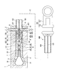
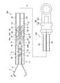
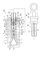
- FIG. 1 is an overall view showing a cartridge and a clip system according to a first embodiment.
- FIG. 1 is an overall view showing a cartridge and a clip system according to a first embodiment.
- FIG. 1 is an overall view showing a cartridge and a clip system according to a first embodiment. It is a perspective view showing an engagement member of a first embodiment.
- It is a schematic diagram which shows the usage aspect of the cartridge and the clip system which concern on 1st embodiment.
- It is a schematic diagram which shows the usage aspect of the cartridge and the clip system which concern on 1st embodiment.
- It is a schematic diagram which shows the usage aspect of the cartridge and the clip system which concern on 1st embodiment.
- It is a schematic diagram which shows the usage aspect of the cartridge and the clip system which concern on 1st embodiment.
- FIG. 7 is an overall view showing a modified example of the cartridge and the clip system according to the first embodiment.
- FIG. 7 is an overall view showing a modified example of the cartridge and the clip system according to the first embodiment.
- It is a schematic diagram which shows the cartridge and the clip system which concern on 2nd embodiment.
- It is a schematic diagram which shows the cartridge and the clip system which concern on 2nd embodiment.
- It is a schematic diagram which shows the cartridge and clip system which concern on 3rd embodiment.
- 1 to 3 are overall views showing a cartridge 1 and a clip system 200 according to this embodiment.
- FIG. 1 to FIG. 3 are views showing an aspect at each step of using the cartridge 1.
- the clip system 200 includes a clip unit 4, an applicator 100, a cartridge 1, and a pusher 2.
- the clip system 200 is a system in which the applicator 100 to which the clip unit 4 is attached is inserted into a publicly known endoscope insertion portion so that the clip unit 4 can be left inside the body.
- the clip system 200 is configured such that the clip unit 4 can be attached to the applicator 100 multiple times using the cartridge 1.
- the center line in the longitudinal direction when the applicator 100 extends linearly is referred to as the longitudinal axis C.
- the operation unit 160 side of the applicator 100 is referred to as a proximal side, and the side opposite to the proximal side in the longitudinal axis C direction and provided with the clip unit 4 is referred to as a distal side.
- the clip unit 4 includes a housing 7 and an arm member 3. As shown in FIG. 1, the housing 7 has a tubular shape with a hole 70 penetrating in the longitudinal axis C direction.
- the hole 70 of the housing 7 is a circular hole, and is formed by communicating a first insertion hole 71 (insertion hole) formed on the proximal side and a second insertion hole 72 formed on the distal side. There is.
- the first insertion hole 71 is an elongated hole having a larger opening diameter than the second insertion hole 72.
- the first insertion hole 71 has an opening diameter in which a sheath described later can be placed.
- a step is formed at a boundary portion between the first insertion hole 71 and the second insertion hole 72, and a distal end of the first insertion hole 71 extends from the proximal end of the second insertion hole 72 to the longitudinal axis C.
- a distal wall 74 is formed that extends outwardly in a perpendicular direction.
- the second insertion hole 72 has an opening size into which the arm member 3 can be inserted.
- the distal end portion of the second insertion hole 72 is formed with a tapered surface 73 that slightly expands toward the distal end surface of the housing 7.
- the housing 7 is made of metal material such as stainless steel, titanium alloy (Ti-6AL-4V, etc.), cobalt chrome alloy, polyphthalamide (PPA), polyamide (PA), etc. It is made using a resin material.
- the arm member 3 has one or more arms 31.
- the arm member 3 includes a pair of arms 31 (first arm, second arm) and a connecting portion 33 on the proximal side of each arm 31.
- the arm member 3 is made of, for example, a thin and slender plate made of metal such as stainless steel, cobalt chrome alloy, and titanium.
- Each of the pair of arms 31 has a U-shaped connecting portion 33 formed by bending in the thickness direction in the middle portion of a thin and long plate, and both ends of the plate serve as the pair of arms 31.
- An end portion of each arm 31 on the opposite side of the connection portion 33 is formed with a claw portion 32 bent in a direction toward each other.
- the pair of arms 31 has a bending tendency in a direction in which they are separated from each other from the connecting portion 33 side toward the claw portion 32 side.
- the clip unit 4 further includes a connecting member 9.
- the connecting member 9 is a member that connects the arm member 3 and the operation wire 103.
- the connecting member 9 is provided in the housing 7 at the proximal end of the arm member 3.
- the connecting member 9 includes a first connecting body 92 and a second connecting body 93, and is configured by engaging the first connecting body 92 and the second connecting body 93 side by side in the longitudinal axis C direction. ..
- the first connecting body 92 is located at the proximal portion of the connecting member 9 and is engaged with the operation wire 103.
- a wire engaging portion 94 is provided at the proximal end of the first connecting body 92.
- the wire engagement portion 94 includes an engagement hole 941, a pair of engagement arms 942, and a locking portion 943.
- the engagement hole 941 is a hole that opens in the proximal end surface of the first coupling body 92, and has a size that allows the connector 104 of the operation wire 103 described below to be inserted.
- a pair of engagement arms 942 are provided at the proximal edge of the engagement hole 941 so as to project in the proximal direction.
- the pair of engagement arms 942 are each configured to be able to bend outward in the radial direction of the first coupling body 92.
- a locking portion 943 is provided at each of the proximal ends of the pair of engagement arms 942.
- the locking portion 943 is provided at a position facing the engagement hole 941 and covering the opening.
- the distal portion of the first coupling body 92 is provided with a cylindrical portion 921 extending distally along the longitudinal axis C direction and a conical portion 922.
- the conical portion 922 is provided at the distal end of the columnar portion 921, and the pointed end is disposed at the distal end of the first coupling body 92.
- the diameter of the proximal portion of the conical portion 922 is larger than the diameter of the cylindrical portion 921.
- the second connecting body 93 is located on the distal side of the first connecting body 92 and is engaged with the arm member 3.
- the second connecting body 93 includes a connecting portion 931 forming a proximal region and a hook 932 forming a distal region.
- the connecting portion 931 includes an engaging hole 933, a pair of engaging arms 934, and a locking portion 935 at the proximal end portion.
- the engagement hole 933, the pair of engagement arms 934, and the locking portion 935 have the same configuration as the wire engagement portion 94 of the first coupling body 92.
- the conical portion 922 of the first connecting body 92 is inserted into the engaging hole 933 of the second connecting body 93, and the conical portion 922 is engaged by the pair of engaging arms 934 and the locking portion 935 of the second connecting body 93.
- the first connecting body 92 and the second connecting body 93 are connected.
- the hook 932 is a hook that is substantially L-shaped when viewed from the direction of arrow A in FIG. 1, and is provided so as to project farther than the connecting portion 931.
- the arm 31 of the arm member 3 and the connecting member 9 are locked in the first insertion hole 71 of the housing 7.
- the L-shaped end portion of the hook 932 of the second connecting body 93 is arranged inside the curved portion of the connecting portion 33 of the arm member 3, and is inserted into the first insertion hole 71 in this state. There is. With this configuration, the hook 932 does not disengage from the connecting portion 33 in the longitudinal axis C direction and the radial direction of the housing 7 in the first insertion hole 71, and the arm member 3 and the connecting member 9 are engaged with each other.
- the first insertion hole 71 has a size such that the locked arm member 3 and the connecting member 9 can advance and retreat in the first insertion hole 71 in the longitudinal axis C direction. Although details will be described later, the arm member 3 and the connecting member 9 can be moved back and forth in the first insertion hole 71 as the operation wire 103 connected to the first connected body 92 is moved back and forth.
- the arm member 3 is configured such that the pair of arms 31 can be opened and closed according to the relative position of the arm member 3 with respect to the first insertion hole 71 in the longitudinal axis C direction.
- the applicator 100 includes a sheath 101, an operation wire 103, an engagement member 8, and an operation section 160.
- the operation unit 160 includes an operation body 161 and a slider 162.
- the slider 162 is provided slidably in the longitudinal axis C direction with respect to the operation body 161.
- the sheath 101 is a flexible, long tubular member.
- the sheath 101 has a conduit 111 formed along the longitudinal axis C over the entire length.
- the sheath 101 is, for example, a coil sheath formed by tightly winding a wire made of stainless steel such as SUS301 around the longitudinal axis C.
- the proximal end of the sheath 101 is connected to the operation body 161 of the operation unit 160.
- the conduit 111 opens into the distal end 106 of the sheath 101.
- the distal end portion 105 of the sheath 101 is formed with a convex portion 109 that projects radially inward from the inner peripheral surface of the duct 111.
- the convex portion 109 projects annularly from the inner peripheral surface of the entire circumference of the conduit 111.
- the opening of the conduit 111 is narrowed at the position of the convex portion 109, but the conduit 111 is secured to such an extent that the operation wire 103 and the intermediate portion 83 of the engagement member 8 described later can be advanced and retracted.
- a through hole (opening) 107 communicating with the inside and outside of the sheath 101 is formed at the distal end 105 of the sheath 101.
- the through hole 107 is located closer to the proximal side than the convex portion 109.
- a pair of through holes 107 are formed at positions facing each other on the circumference of the sheath 101.
- the through hole 107 has an opening into which the pusher 2 can be inserted.
- the operation wire 103 is inserted into the sheath 101.
- the proximal end of the operating wire 103 is fixed to the slider 162 of the operating portion 160, and the connector 104 is fixed to the distal end of the operating wire 103.
- the operation wire 103 is formed of a metal single wire or a stranded wire.
- the connector 104 is a member that connects the arm member 3 and the operation wire 103.
- the connector 104 includes a connecting end 1041, an engaged portion 1042, and a recess 1043.
- the connecting end 1041 has a tubular shape, and the distal end of the operating wire 103 is inserted and fixed to the operating wire 103.
- the engaged portion 1042 is provided at the distal end portion of the connector 104.
- the engaged portion 1042 has a conical shape, projects in the direction of the longitudinal axis C, and has a pointed end on the distal side.
- the recess 1043 is located between the proximal end of the engaged portion 1042 and the connecting end 1041 and has a cylindrical shape with an outer diameter smaller than that of the engaged portion 1042 and the connecting end 1041.
- the engaging member 8 is attached to the distal end portion of the operation wire 103, and is provided so as to be able to project and retract from the distal end of the sheath 101.
- FIG. 4 shows a perspective view of the engaging member 8.
- the engagement member 8 includes a proximal end portion 81, an intermediate portion 83, and a distal end portion 82 along the longitudinal axis C direction, and the engaging member 8 extends along the longitudinal axis C direction over the entire length.
- An insertion hole 85 extending in the direction is formed.
- the proximal end portion 81 includes an annular portion 811 and a tapered portion 812.
- the annular portion 811 has an annular shape whose diameter is smaller than the inner diameter of the conduit 111 of the sheath 101.
- the tapered portion 812 is located closer to the proximal side than the annular portion 811, and has a substantially conical shape in which the diameter is reduced in the proximal direction from the outer peripheral end portion on the proximal side of the annular portion 811.
- the distal end portion 82 has a substantially cylindrical shape.
- a chamfered beveled surface 823 is provided at a boundary portion between the outer peripheral surface of the distal end portion 82 and the distal end surface 822.
- the middle portion 83 is located between the proximal end 81 and the distal end 82.
- the intermediate portion 83 has a substantially cylindrical shape whose diameter is smaller than the outer diameters of the annular portion 811 of the proximal end portion 81 and the distal end portion 82. Therefore, in the engaging member 8, the intermediate portion 83 between the proximal end portion 81 and the distal end portion 82 is a recess.
- a first contact wall 813 extending in the direction intersecting the longitudinal axis C is provided between the proximal end of the intermediate portion 83 and the distal end of the outer peripheral portion of the annular portion 811.
- a second contact wall 821 extending in a direction intersecting the longitudinal axis C is provided between the distal end of the intermediate portion 83 and the proximal end of the outer peripheral portion of the distal end portion 82.
- a pair of slits 86 extending from the distal end surface 822 of the engaging member 8 in the longitudinal axis C direction are provided.
- the pair of slits 86 are opposed to each other with the central axis of the cylindrical distal end portion 82 interposed therebetween, that is, on the diameter of the distal end portion 82. It is formed in two places.
- the pair of slits 86 are formed so as to extend in the longitudinal axis C direction from the distal end surface 822 to the substantially central portion of the engaging member 8 in the longitudinal axis C direction. Therefore, the distal end portion 82 is connected to the intermediate portion 83 while being divided into a semicircle by the pair of slits 86.
- the pair of slits 86 extend to the intermediate portion 83.
- the insertion hole 85 has a different opening size with the substantially central portion of the engaging member 8 in the longitudinal axis C direction as a boundary.
- the opening size of the insertion hole 85 is larger in the second insertion hole 852 in the distal portion than in the first insertion hole 851 in the proximal portion.
- the second insertion hole 852 has an inner tapered surface 853 whose opening diameter increases toward the distal end surface 822.
- the pair of slits 86 extend from the distal end surface 822 to the proximal end of the second insertion hole 852.
- the distal region of the intermediate portion 83 is thinner than the proximal region of the intermediate portion 83 and the distal end portion 82.
- the engaging member 8 is The distal side bends, and the divided distal ends 82 come closer to each other.
- the operation wire 103 is inserted into the insertion hole 85 so that the operation wire 103 can move forward and backward.
- the distal portion of the operation wire 103 penetrates the first insertion hole 71, and the connector 104 is inserted into the second insertion hole 852.
- the outer dimensions of the distal portion of the coupling end 1041 and the engaged portion 1042 are larger than the opening dimension of the first insertion hole 71. Therefore, the connector 104 contacts the distal end of the first insertion hole 71 when retracting with respect to the engagement member 8. Therefore, the operation wire 103 does not come off from the engagement member 8 to the proximal side.
- the engagement member 8 is arranged in the distal end portion 105 of the sheath 101.
- the intermediate portion 83 of the engaging member 8 is inserted inside the annular convex portion 109 of the sheath 101.
- the engagement member 8 is provided so as to be able to advance and retract within the distal end portion 105 of the sheath 101.
- the opening diameter inside the convex portion 109 is larger than the outer diameter of the intermediate portion 83 and smaller than the outer diameters of the proximal end portion 81 and the distal end portion 82.
- the engagement member 8 is located between the position where the first contact wall 813 of the proximal end 81 contacts the protrusion 109 and the position where the second contact wall 821 of the distal end 82 contacts the protrusion 109. It is configured to be able to move forward and backward.
- the engaging member 8 advances, the first abutment wall 813 of the proximal end 81 abuts the protrusion 109, and further advancement is restricted.
- the engaging member 8 retracts the second contact wall 821 of the distal end portion 82 abuts the convex portion 109 and further retracting is restricted. Therefore, the amount of forward/backward movement of the engagement member 8 with respect to the sheath 101 is defined by the distance between the first contact wall 813 and the second contact wall 821.
- the length of the distal end portion 82 in the longitudinal axis C direction is slightly shorter than the length from the distal end 106 of the sheath 101 to the distal end of the convex portion 109. Therefore, as shown in FIG. 1, when the position of the engagement member 8 with respect to the sheath 101 is at the most retracted position, the engagement member 8 is housed inside the sheath 101 over the entire length. When the engaging member 8 is in the retracted position, the proximal end portion 81 is arranged at the position of the through hole 107 of the sheath 101 in the longitudinal axis C direction.
- the pusher 2 is configured to move the pusher 2 with respect to the sheath 101 by contacting the engaging member 8 and pushing the engaging member 8.
- the pusher 2 is provided in the cartridge 1.
- the cartridge 1 accommodates the clip unit 4 before use, and the clip unit 4 can be attached to the applicator 100.
- the cartridge 1 includes a main body 11, and the main body 11 is provided with a pusher 2.
- the main body 11 has a storage portion 12 in which the clip unit 4 is stored.
- the storage portion 12 is a hollow portion formed according to the outer shape of the clip unit 4.
- the storage portion 12 has a first storage portion 121 (insertion hole) for storing the housing 7 of the clip unit 4, and a second storage portion 122 for storing the distal region of the arm member 3 protruding from the housing 7.
- First storage section 121 has an elongated shape.
- the first accommodating portion 121 has an insertion hole (opening) 15 which is opened at the base end of the main body 11 and into which the sheath 101 can be inserted along the longitudinal axis C direction.
- the first storage portion 121 is configured to be insertable along the longitudinal axis C direction (axial direction).
- the first storage portion 121 is longer than the length of the housing 7 in the longitudinal axis C direction.
- the pusher 2 is provided at the proximal end of the main body 11.
- the main body 11 has a slide hole 13 that communicates between the proximal portion of the first storage portion 121 and the outer surface of the main body 11.
- the slide hole 13 is a hole extending in a direction orthogonal to the longitudinal axis C direction.
- the pusher 2 is an elongated rod-shaped member and is inserted into the slide hole 13. As shown in FIGS. 1 and 3, the pusher 2 is configured to be movable in a direction intersecting the longitudinal axis C of the first storage portion 121.
- the pusher 2 is provided with a biasing member (not shown), and in a natural state in which the pusher 2 is not subjected to an external force, as shown in FIG.
- the pusher 2 has an inclined surface 21 that is inclined with respect to the longitudinal axis C.
- the inclined surface 21 has a shape in which a corner portion on the distal side of the inner end surface 22 of the pusher 2 facing the first storage portion 121 side is chamfered.
- FIG. 9 is a flowchart showing the engagement method according to this embodiment.
- the clip unit 4 is housed in the housing portion 12 of the cartridge 1 in advance with the arm 31 in the distal region of the arm member 3 protruding from the housing 7 to the distal side.
- the clip unit 4 housed in the housing 12 has the housing 7 housed in the distal region of the first housing 121.
- a space into which the sheath 101 is inserted is formed on the proximal side of the housing 7.
- the cartridge 1 is brought close to the distal end 106 of the sheath 101, and the distal end 106 is inserted into the insertion hole 15 of the first storage portion 121 of the cartridge 1 (first step S1).
- the sheath 101 is advanced to the cartridge 1 side, and the distal end 106 of the sheath 101 is brought into contact with the proximal end of the housing 7, as shown in FIG.
- the operator operates the slider 162, advances the operation wire 103, and pushes the engaged portion 1042 into the engagement hole 941 side.
- the tip of the engaged portion 1042 enters the engaging hole 941 from between the pair of engaging arms 942, bends in the direction in which the pair of engaging arms 942 separates, and the engaged portion 1042 engages with the engaging hole 941. Inserted inside. Since the engaging hole 941 of the wire engaging portion 94 has a shape similar to the shape of the engaged portion 1042, the engaged portion 1042 is arranged in the proximity of the engaging hole 941.
- the engaged portion 1042 When the engaged portion 1042 is inserted into the engaging hole 941, the pair of engaging arms 942 return to their natural positions, and the locking portion 943 abuts on the proximal end surface of the engaged portion 1042. As a result, the engaged portion 1042 is engaged in the engaging hole 941 and the distal end of the operation wire 103 is engaged with the connecting member 9.
- the pusher 2 is movable with respect to the sheath 101, and when the pusher 2 moves with respect to the sheath 101, the pusher 2 comes into contact with the engaging member 8 and pushes the engaging member 8 against the housing, thereby separating the engaging member 8 from the sheath 101 and the housing. Both are engaged (second step S2).
- the pusher 2 protruding into the first storage portion 121 passes through the through hole 107 of the sheath 101 and contacts the proximal end portion 81 of the engaging member 8.
- the inclined surface 21 of the pusher 2 is pushed in while contacting the tapered portion 812 of the proximal end portion 81, as shown in FIG. As a result, the engagement member 8 advances distally.
- the engaging member 8 When the pusher 2 is pushed to the innermost side with respect to the first insertion hole 71, the engaging member 8 is at the most advanced position, and the housing 7 and the sheath 101 are engaged with each other via the engaging member 8. Has been done. Therefore, when the operator releases the pressing force on the pusher 2 after pushing the pusher 2 into the first insertion hole 71 to the innermost side, the urging member provided in the pusher 2 returns the retracted position shown in FIG. .. In this state, the cartridge 1 is moved in the distal direction, and the clip unit 4 is taken out from the cartridge 1.
- the clip unit 4 is inserted into the body through the treatment tool channel of the endoscope and brought close to the tissue to be ligated by the arm member 3. Since the housing 7 is engaged with the sheath 101 by the engaging member 8, when the sheath 101 is rotated about the longitudinal axis C, the housing 7 is also rotated and the arm 31 of the arm member 3 rotates about the longitudinal axis C. The orientation can be adjusted.
- the operation wire 103 is moved forward with respect to the sheath 101 and the engaging member 8 as shown in FIG.
- the arm member 3 advances with respect to the housing 7, and the pair of arms 31 projects from the second storage portion 122 to the distal side.
- the portions of the pair of arms 31 projecting distally from the second storage portion 122 are released in a direction in which they are released from the pressing force of the second storage portion 122.
- the sheath 101 and the housing 7 are engaged with each other via the engaging member 8, and the operation wire 103 is configured to be able to move forward and backward in this state. Therefore, the arm member 3 can move forward and backward with respect to the housing 7. Is. As a result, the tissue can be regripped by the arm member 3. That is, once the tissue is sandwiched by the pair of claw portions 32 of the arm member 3, the pair of arms 31 can be opened again by moving the arm member 3 forward relative to the housing 7. The state in which 32 holds the tissue can be released. Furthermore, when the arm member 3 is brought closer to the tissue again with the pair of arms 31 open and retracted relatively to the housing 7, the tissue can be sandwiched by the pair of claw portions 32 again.
- the operator When the operator can grasp the tissue with the arm member 3 in a desired state, the operator retracts the slider 162 and retracts the operation wire 103 and the arm member 3.
- the operation wire 103 and the arm member 3 retract while the tissue is held between the pair of claw portions 32, tension is applied to the connecting body 92.
- the pair of engaging arms 934 of the second coupling body 93 are pushed and deformed by the conical portions 922 in the directions in which they are separated from each other, and the conical portions 922 fall out from the engaging holes 933.
- the engagement between the first connecting body 92 and the second connecting body 93 is released.
- the pair of engagement arms 942 of the first connection body 92 are tapered inside the second insertion hole 852. It abuts the surface 853.
- the pair of engaging arms 942 of the first connecting body 92 maintains the engaged state of the engaged portion 1042.
- the pair of engagement arms 942 apply a force in the backward direction while contacting the inner tapered surface 853. Therefore, as the operation wire 103 is retracted, a force is applied to the engagement member 8 in the proximal direction, and the engagement member 8 retracts with respect to the housing 7.
- the engaging member 8 When the engaging member 8 is pushed proximally by the first connecting body 92, it disengages from the first insertion hole 71 as shown in FIG. 8, and the engagement between the sheath 101 and the housing 7 by the engaging member 8 is released. To be done. That is, the engagement releasing operation between the first connecting body 92 and the second connecting body 93 and the engagement releasing operation between the sheath 101 and the housing 7 by the engaging member 8 are performed substantially at the same time. After the engagement between the housing 7 and the sheath 101 is released, the sheath 101 is retracted and the tissue is ligated by the clip unit 4.
- the applicator 100 After ligating the tissue with the first clip unit 4, the applicator 100 is pulled out of the body, and the second clip unit 4 is loaded on the applicator 100 again as needed. Specifically, after the applicator 100 is removed from the body, the operation wire 103 is projected from the distal end 106 of the sheath 101, and the first connection body 92 connected to the connector 104 of the operation wire 103 is removed. Next, the second cartridge 1 containing the second clip unit 4 is prepared. The operation wire 103 is retracted, the sheath 101 is inserted into the cartridge 1 by the same method as described above, and the cartridge 1 and the sheath 101 are engaged with each other via the engaging member 8. As a result, the clip unit 4 is loaded on the sheath 101. In this way, when ligating a plurality of places of the tissue with the plurality of clip units 4, the clip units can be continuously loaded without exchanging the applicator 100.
- the clip unit 4 can be easily loaded in the applicator 100, and the clip unit 4 can be repeatedly loaded in the applicator 100.
- the distal end portion 105 of the sheath 101 is inserted into the insertion hole 15 of the main body 11, and the pusher 2 is movable in the direction intersecting with the main body 11. Further, the pusher 2 can push the engaging member 8 in the forward direction with respect to the housing 7. By engaging the engaging member 8 with both the housing 7 and the sheath 101 by the pusher 2, the engaging member 8 engages with the sheath 101 and the housing 7. As a result, the clip unit 4 can be attached to the applicator 100 by a simple operation of pushing the pusher 2 with the sheath 101 inserted in the main body 11.
- the pusher 2 is configured to be movable in the direction intersecting the longitudinal axis C of the elongated first insertion hole 71. That is, the inserting direction of the sheath 101 into the cartridge 1 and the pressing direction of the engaging member 8 against the cartridge 1 are along the longitudinal axis C.
- the pusher 2 moves in the direction intersecting the longitudinal axis C and pushes the engaging member 8. Therefore, the engagement member 8 is smoothly moved in the longitudinal axis C direction by moving the pusher 2 in a direction different from the movement direction of the operation wire 103 while maintaining the state in which the sheath 101 is inserted in the main body 11 of the cartridge 1. You can press it. As a result, it is possible to engage the sheath 101 and the housing 7 by pushing the pusher 2 and advancing the engaging member 8 while keeping the cartridge 1 in contact with the distal end 106 of the sheath 101.
- the engagement member 8 can be advanced with the sheath 101 inserted in the first insertion hole 71.
- the pusher 2 is accommodated in the sheath 101 by protruding into the first insertion hole 71 through the through hole 107 formed in the outer peripheral surface of the sheath 101. Contact the mating member 8. As a result, with the sheath 101 inserted in the first insertion hole 71, the pusher 2 can contact the engagement member 8 arranged in the sheath 101, and the engagement member 8 can be pushed by the pusher 2. ..
- the pusher 2 is provided with the inclined surface 21, and the inclined surface 21 is configured to be capable of contacting the engaging member 8.
- the engaging member 8 can be advanced while moving the pusher 2 in a direction different from the forward direction of the engaging member 8.
- the proximal end portion 81 of the engaging member 8 has the tapered portion 812
- the pusher 2 has the inclined surface 21
- the tapered portion 812 and the inclined surface 21 are in contact with each other.
- the clip system is not limited to this configuration example, and may have a configuration in which one of the pusher and the engaging member has an inclined surface.
- the cartridge 1 is attached to the distal end 106 of the sheath 101 to project the engagement member 8 from the distal end 106 of the sheath 101.
- the engaging member 8 can be moved with a simpler configuration. Can be pushed.
- the sheath 101 can be inserted in the longitudinal axis C direction from the proximal side of the first insertion hole 71
- the insertion form of the sheath into the insertion hole is not limited to this.
- the sheath may be inserted into the insertion hole from the side of the main body of the cartridge.
- the pusher 2 projects into the first insertion hole 71 through the through hole 107 formed in the outer peripheral surface of the sheath 101 to contact the engagement member 8 housed in the sheath 101.
- the mode in which the pusher 2 projects into the first insertion hole 71 is not limited to this.
- the through hole 107 is covered with an elastically deformable elastic film 1071, and the elastic film 1071 is pressed by the pusher 2 to deform the elastic film 1071. You may project in the 1st insertion hole 71.
- the pusher 2 can push the engaging member 8 with the elastic film 1071 sandwiched between the pusher 2 and the engaging member 8.
- FIGS. 12 and 13 a clip system 200A according to the second embodiment will be described with reference to FIGS. 12 and 13.
- the same components as those already described in the first embodiment will be assigned the same reference numerals and overlapping description will be omitted.
- the present embodiment differs from the first embodiment in the configuration in which the pusher pushes the engagement member against the housing 7.
- the sheath 101 of this embodiment is a coil sheath that does not have the convex portion 109 and the through hole 107.
- the pusher 2A is housed in the sheath 101.
- the pusher 2A of the present embodiment is provided at the distal end 1021 of the inner sheath 102.
- the inner sheath 102 is inserted into the sheath 101, and the operation wire 103 is inserted inside. That is, the inner sheath 102 is arranged coaxially with the sheath 101 between the operation wire 103 and the sheath 101.
- the inner sheath 102 is a coil sheath.
- a proximal end portion of the inner sheath 102 is fixed to a second slider 163 provided on the operation portion 160A.
- the second slider 163 can move forward and backward with respect to the operation body 161.
- the pusher 2A is a substantially cylindrical member and is fixed to the distal end 1021 of the inner sheath 102. Therefore, the inner sheath 102 moves back and forth with respect to the sheath 101 by the forward/backward operation of the second slider 163, and the pusher 2A moves forward/backward as the inner sheath 102 moves forward/backward.
- the pusher 2A is formed with an insertion hole 27 penetrating in the longitudinal axis C direction.
- the pusher 2A is fixed to the inner sheath 102 with the insertion hole 27 and the central axis of the conduit 1022 of the inner sheath 102 arranged coaxially.
- the engagement member 8A of the present embodiment is made of a substantially cylindrical tubular member.
- the engagement member 8A is inserted into the conduit 111 of the distal end portion 105 of the sheath 101.
- the outer peripheral surface of the engaging member 8A has an outer dimension that allows frictional engagement with the inner surface of the sheath 101 and the inner surface of the first storage portion 121.
- the engagement member 8A can advance and retreat in the pipe line 111 and the first storage part 121.
- the engagement member 8A frictionally engages with the inner surface of the sheath 101 and the first storage portion 121.
- the engagement member 8A is formed with an insertion hole 85A extending in the longitudinal axis C direction over the entire length.
- a distal pusher 108 is fixed to the operation wire 103.
- the distal pusher 108 is fixed to the distal end region of the operation wire 103, which is closer to the proximal side than the connector 104.
- the distal pusher 108 is a cylindrical member.
- the diameter of the distal pusher 108 is smaller than the inner diameter of the sheath 101 and the inner diameter of the first storage portion 121 of the housing 7, and larger than the inner diameter of the insertion hole 85A of the engaging member 8A.
- the operation wire 103 is inserted into the sheath 101 and the inner sheath 102, and the distal portion is inserted into the insertion hole 85A of the engaging member 8A.
- the connector 104 and the distal pusher 108 are arranged on the distal side of the engagement member 8A.
- the cartridge 1A does not include the pusher 2 and the slide hole 13 of the first embodiment, and other configurations are the same as those of the first embodiment.
- the distal end 106 of the sheath 101 is inserted into the insertion hole 15 of the cartridge 1A in which the clip unit 4 is housed, and brought into contact with the proximal end 75 of the housing 7. Similar to the first embodiment, the operation wire 103 is advanced to push the engaged portion 1042 into the engaging hole 941 side of the clip unit 4 and engage the connector 104 with the connecting member 9.
- the second slider 163 is advanced with respect to the operation body 161, and the inner sheath 102 is advanced with respect to the sheath 101.
- the second slider 163 is further advanced.
- the pusher 2A pushes the engagement member 8A in the distal direction
- the engagement member 8A advances
- the pusher 2A projects further to the distal side than the distal end 106 of the sheath 101. As shown in FIG.
- the cartridge 1A is removed from the clip unit 4, and the mounting of the clip unit 4 on the sheath 101 is completed. Then, as in the first embodiment, the distal end portion 105 of the sheath 101 is inserted into the body, and the target tissue is ligated with the clip unit 4.
- the engagement between the housing 7 and the sheath 101 is released.
- the slider 162 of the operation unit 160 is slid proximally.
- the pair of engagement arms 934 of the second coupling body 93 are pushed by the conical portions 922 in a direction in which they are separated from each other and are deformed, and the conical portions 922 fall out from the engaging holes 933.
- the engagement between the first connecting body 92 and the second connecting body 93 is released.
- the distal pusher 108 pushes the engagement member 8A proximally, the engagement member 8A moves proximally, and the engagement between the housing 7 and the sheath 101 by the engagement member 8A is released. ..
- the tissue is ligated by the clip unit 4.
- the clip unit 4 can be easily loaded into the applicator 100, and the clip unit can be repeatedly loaded into the applicator 100, as in the first embodiment.
- the pusher 2A is configured to be able to come into contact with the proximal end 801 of the engaging member 8A by advancing and retracting with respect to the operation wire 103, and the engaging member 8A is the first housing of the housing 7. It can be press-fitted into the portion 121. As a result, the housing 7 and the sheath 101 can be engaged by moving the engaging member 8A in the sheath 101 forward and backward. Therefore, the housing 7 and the sheath 101 can be engaged with each other with a simple configuration.
- the engaging member 8A can be pushed and moved to the proximal side by retracting the operation wire 103. Therefore, the engagement member 8A can be moved back and forth with respect to the sheath 101 and the housing 7. As a result, the clip unit 4 can be attached to and detached from the sheath 101. Further, the clip unit 4 can be repeatedly loaded in the applicator 100.
- a clip system 200A according to the third embodiment will be described with reference to FIGS. 14 and 15.
- the structure of the engaging member and the structure in which the pusher pushes the engaging member against the housing 7 are different from the first embodiment.
- the applicator 100B includes an outer sheath 119 as shown in FIG.
- the outer sheath 119 functions as a pusher of the engagement member 8B.
- the outer sheath 119 is arranged coaxially with the sheath 101, and the sheath 101 having the operation wire 103 inserted therein is inserted therein.
- a grip portion 1191 is provided at the proximal end of the outer sheath 119.
- the outer sheath 119 is provided so as to be movable back and forth in the longitudinal axis C direction with respect to the sheath 101.
- the outer sheath 119 includes an engaging member 8B.
- the engagement member 8B is fixed to the distal end of the outer sheath 119.
- the engagement member 8B is a tubular member into which the sheath 101 and the housing 7 can be inserted.
- the engagement member 8B is, for example, a soft resin tube or a coil whose diameter can be reduced.
- the engagement member 8B is provided so as to be able to advance and retreat with respect to the sheath 101 and the housing 7 while being in contact with the outer peripheral surfaces of the sheath 101 and the housing 7.
- the engaging member 8B Since the engaging member 8B is fixed to the distal end of the outer sheath 119, the engaging member 8B advances toward the housing 7 in the distal direction as the outer sheath 119 advances.
- the engaging member 8B is configured to be able to engage the housing 7 and the sheath 101 by friction between the outer peripheral surface of the housing 7 and the outer peripheral surface of the sheath 101.
- the sheath 101 of this embodiment is a coil sheath that does not include the convex portion 109 and the through hole 107.
- the same cartridge 1A as that in the second embodiment is used.
- the distal end 106 of the sheath 101 is inserted into the insertion hole 15 of the cartridge 1A in which the clip unit 4 is housed, and brought into contact with the proximal end 75 of the housing 7. Similar to the first embodiment, the operation wire 103 is advanced to push the engaged portion 1042 into the engaging hole 941 side of the clip unit 4, and the connector 104 is engaged with the connecting member 9.
- the operator grasps the grasping portion 1191 and advances the outer sheath 119 with respect to the sheath 101.
- the engaging member 8B advances, projects further distal than the distal end 106 of the sheath 101, and the distal end 802 of the engaging member 8B enters into the insertion hole 15 of the cartridge 1A. ..
- the distal end 106 of the sheath 101 and the proximal end 75 of the housing 7 are inserted into the engaging member 8B as shown in FIG.
- the inner peripheral surface of the engagement member 8B contacts the outer peripheral surfaces of the sheath 101 and the housing 7, and the distal end 106 of the sheath 101 and the proximal end 75 of the housing 7 are engaged with each other via the engagement member 8B.
- the cartridge 1A is removed from the clip unit 4, and the mounting of the clip unit 4 on the sheath 101 is completed. Then, as in the first embodiment, the distal end portion 105 of the sheath 101 is inserted into the body, and the target tissue is ligated with the clip unit 4.
- the engagement between the housing 7 and the sheath 101 is released.
- the grip portion 1191 of the outer sheath 119 is slid proximally.
- the engaging member 8B moves to the proximal side, and the engagement between the housing 7 and the sheath 101 by the engaging member 8B is released.
- the pair of engagement arms 934 of the second coupling body 93 are pushed and deformed by the conical portions 922 in the directions in which they are separated from each other, and the conical portions 922 are engaged. Fall out of the hole 933.
- the engagement between the first connecting body 92 and the second connecting body 93 is released.
- the tissue is ligated by the clip unit 4.
- the engagement between the housing 7 and the sheath 101 by the engagement member 8B may be released after the operation for releasing the engagement between the first connecting body 92 and the second connecting body 93.
- the clip unit 4 can be easily loaded in the applicator 100B, and the clip unit 4 can be repeatedly loaded in the applicator 100B, as in the first embodiment.
- the engaging member 8B is fixed to the distal end of the outer sheath 119, and the engaging member 8B can be moved forward and backward by moving the outer sheath 119 forward and backward relative to the sheath 101.
- the housing 7 and the sheath 101 can be engaged by the forward movement of the engaging member 8B outside the sheath 101. Therefore, the housing 7 and the sheath 101 can be engaged with each other with a simple configuration.
- the engaging member 8B since the outer sheath 119 is provided with the engaging member 8B, the engaging member 8B is moved to the proximal side by retracting the outer sheath 119. Therefore, the engaging member 8B can be moved back and forth with respect to the sheath 101 and the housing 7. As a result, the clip unit 4 can be attached to and detached from the sheath 101. Further, the clip unit 4 can be repeatedly loaded in the applicator 100B.
- the clip can be easily reloaded into the applicator. It is possible to provide a cartridge, a clip system, and an engaging method that can easily select right and left by using a switch attached to a housing.
Landscapes
- Health & Medical Sciences (AREA)
- Surgery (AREA)
- Life Sciences & Earth Sciences (AREA)
- Heart & Thoracic Surgery (AREA)
- Nuclear Medicine, Radiotherapy & Molecular Imaging (AREA)
- Vascular Medicine (AREA)
- Engineering & Computer Science (AREA)
- Biomedical Technology (AREA)
- Reproductive Health (AREA)
- Medical Informatics (AREA)
- Molecular Biology (AREA)
- Animal Behavior & Ethology (AREA)
- General Health & Medical Sciences (AREA)
- Public Health (AREA)
- Veterinary Medicine (AREA)
- Surgical Instruments (AREA)
Abstract
La carpule (1) de l'invention est équipée : d'un corps principal (11) qui admet une unité pince (4) équipée d'un élément bras (3) et d'un logement (7) de forme tubulaire, qui est configuré de manière à permettre l'installation de ladite unité pince dans un applicateur (100) possédant une gaine (101) et un câble de manipulation (103), et qui possède un orifice d'insertion (15) dans lequel est insérée ladite gaine ; et d'un poussoir (2) capable de se déplacer vis-à-vis dudit corps principal. Ledit poussoir est configuré de sorte qu'il peut venir en contact avec un élément de mise en prise (8) agencé sur ladite gaine du fait de son déplacement vis-à-vis dudit corps principal dans un état dans lequel ladite gaine est insérée dans ledit orifice d'insertion, il pousse ledit élément de mise en prise vers ledit logement, et il met en prise ladite gaine et ledit logement en mettant en prise ledit élément de mise en prise à la fois avec ledit logement et ladite gaine.
Priority Applications (4)
| Application Number | Priority Date | Filing Date | Title |
|---|---|---|---|
| PCT/JP2018/045453 WO2020121401A1 (fr) | 2018-12-11 | 2018-12-11 | Carpule, système de pince, et procédé de mise en prise |
| CN201880100085.7A CN113194849B (zh) | 2018-12-11 | 2018-12-11 | 盒、夹具系统以及夹具的安装方法 |
| CN202410857742.XA CN118557249A (zh) | 2018-12-11 | 2018-12-11 | 盒 |
| US17/342,219 US20210290244A1 (en) | 2018-12-11 | 2021-06-08 | Cartridge, clip system, and method of mounting clip |
Applications Claiming Priority (1)
| Application Number | Priority Date | Filing Date | Title |
|---|---|---|---|
| PCT/JP2018/045453 WO2020121401A1 (fr) | 2018-12-11 | 2018-12-11 | Carpule, système de pince, et procédé de mise en prise |
Related Child Applications (1)
| Application Number | Title | Priority Date | Filing Date |
|---|---|---|---|
| US17/342,219 Continuation US20210290244A1 (en) | 2018-12-11 | 2021-06-08 | Cartridge, clip system, and method of mounting clip |
Publications (1)
| Publication Number | Publication Date |
|---|---|
| WO2020121401A1 true WO2020121401A1 (fr) | 2020-06-18 |
Family
ID=71075979
Family Applications (1)
| Application Number | Title | Priority Date | Filing Date |
|---|---|---|---|
| PCT/JP2018/045453 Ceased WO2020121401A1 (fr) | 2018-12-11 | 2018-12-11 | Carpule, système de pince, et procédé de mise en prise |
Country Status (3)
| Country | Link |
|---|---|
| US (1) | US20210290244A1 (fr) |
| CN (2) | CN118557249A (fr) |
| WO (1) | WO2020121401A1 (fr) |
Families Citing this family (3)
| Publication number | Priority date | Publication date | Assignee | Title |
|---|---|---|---|---|
| CN114431918B (zh) * | 2020-11-06 | 2025-01-10 | 微创优通医疗科技(嘉兴)有限公司 | 一种止血夹 |
| US11589875B1 (en) | 2021-08-25 | 2023-02-28 | GastroLogic LLC | Endoscopic clip apparatus and methods |
| CN116650053A (zh) * | 2022-02-28 | 2023-08-29 | 奥林巴斯医疗株式会社 | 夹子系统、施用器和夹子系统的操作方法 |
Citations (4)
| Publication number | Priority date | Publication date | Assignee | Title |
|---|---|---|---|---|
| JP2008526376A (ja) * | 2005-01-11 | 2008-07-24 | ボストン サイエンティフィック サイムド, インコーポレイテッド | 止血用マルチクリップ展開装置 |
| JP2013544127A (ja) * | 2010-10-11 | 2013-12-12 | クック メディカル テクノロジーズ エルエルシー | 取り外し可能かつ回動可能なジョーを備える医療装置 |
| JP2017148182A (ja) * | 2016-02-23 | 2017-08-31 | 住友ベークライト株式会社 | クリップカートリッジ |
| US20180153552A1 (en) * | 2016-12-06 | 2018-06-07 | Boston Scientific Scimed, Inc. | Compressive coupler for reloadable hemostasis clipping device |
Family Cites Families (19)
| Publication number | Priority date | Publication date | Assignee | Title |
|---|---|---|---|---|
| JP4472217B2 (ja) * | 2000-10-16 | 2010-06-02 | オリンパス株式会社 | 生体組織のクリップ装置 |
| US7494461B2 (en) * | 2003-09-30 | 2009-02-24 | Boston Scientific Scimed, Inc. | Through the scope tension member release clip |
| CN100475165C (zh) * | 2004-12-07 | 2009-04-08 | 奥林巴斯株式会社 | 用于内窥镜的处理装置系统和包括处理装置的壳 |
| US8262678B2 (en) * | 2008-08-21 | 2012-09-11 | Fujifilm Corporation | Clip package for clip application apparatus |
| JP4827904B2 (ja) * | 2008-09-16 | 2011-11-30 | オリンパス株式会社 | 生体組織の結紮装置 |
| JP5427858B2 (ja) * | 2011-09-15 | 2014-02-26 | 富士フイルム株式会社 | 結紮装置、及び内視鏡システム |
| JP5427857B2 (ja) * | 2011-09-15 | 2014-02-26 | 富士フイルム株式会社 | クリップユニット及びこれを用いた結紮装置、並びにクリップユニットの製造方法 |
| WO2013067662A1 (fr) * | 2011-11-11 | 2013-05-16 | Zhu Jian | Dispositif de clampage ou de ligature |
| JP6175850B2 (ja) * | 2013-03-28 | 2017-08-09 | 住友ベークライト株式会社 | クリップカートリッジおよびクリップ装置 |
| CN104869917B (zh) * | 2013-05-07 | 2017-10-10 | 奥林巴斯株式会社 | 内窥镜处理器具 |
| CN104936537B (zh) * | 2013-05-07 | 2017-03-15 | 奥林巴斯株式会社 | 夹具单元 |
| CN104546055A (zh) * | 2013-10-25 | 2015-04-29 | 常州乐奥医疗科技有限公司 | 一种新型可重复闭合的消化道止血夹 |
| JP2017012532A (ja) * | 2015-07-02 | 2017-01-19 | 野村ユニソン株式会社 | 結紮装置用クリップユニット及びクリップユニット用カートリッジ |
| KR101816631B1 (ko) * | 2015-10-07 | 2018-01-09 | 주식회사 파인메딕스 | 내시경용 클립장치 |
| WO2017110450A1 (fr) * | 2015-12-21 | 2017-06-29 | オリンパス株式会社 | Agrafe médicale et système d'outil de traitement |
| JP6784516B2 (ja) * | 2016-06-07 | 2020-11-11 | 野村ユニソン株式会社 | クリップユニット用カートリッジ及びクリップユニット係合方法 |
| WO2018011847A1 (fr) * | 2016-07-11 | 2018-01-18 | オリンパス株式会社 | Outil de traitement endoscopique. |
| CA3027258C (fr) * | 2016-08-22 | 2021-01-05 | Boston Scientific Limited | Dispositif de clipsage pouvant etre recharge par hemostase avec mise en prise par manche |
| US11259815B2 (en) * | 2017-05-04 | 2022-03-01 | Hangzhou Ags Medtech Co., Ltd. | End effector instrument, end effector device, delivery device, and assembly box |
-
2018
- 2018-12-11 WO PCT/JP2018/045453 patent/WO2020121401A1/fr not_active Ceased
- 2018-12-11 CN CN202410857742.XA patent/CN118557249A/zh active Pending
- 2018-12-11 CN CN201880100085.7A patent/CN113194849B/zh active Active
-
2021
- 2021-06-08 US US17/342,219 patent/US20210290244A1/en not_active Abandoned
Patent Citations (4)
| Publication number | Priority date | Publication date | Assignee | Title |
|---|---|---|---|---|
| JP2008526376A (ja) * | 2005-01-11 | 2008-07-24 | ボストン サイエンティフィック サイムド, インコーポレイテッド | 止血用マルチクリップ展開装置 |
| JP2013544127A (ja) * | 2010-10-11 | 2013-12-12 | クック メディカル テクノロジーズ エルエルシー | 取り外し可能かつ回動可能なジョーを備える医療装置 |
| JP2017148182A (ja) * | 2016-02-23 | 2017-08-31 | 住友ベークライト株式会社 | クリップカートリッジ |
| US20180153552A1 (en) * | 2016-12-06 | 2018-06-07 | Boston Scientific Scimed, Inc. | Compressive coupler for reloadable hemostasis clipping device |
Also Published As
| Publication number | Publication date |
|---|---|
| US20210290244A1 (en) | 2021-09-23 |
| CN113194849B (zh) | 2024-07-19 |
| CN118557249A (zh) | 2024-08-30 |
| CN113194849A (zh) | 2021-07-30 |
Similar Documents
| Publication | Publication Date | Title |
|---|---|---|
| US11020126B2 (en) | Endoscopic surgical device | |
| JP6761898B2 (ja) | 再充填可能止血クリップ解放機構 | |
| CN108697428B (zh) | 夹具盒 | |
| US6991634B2 (en) | Clip device of endoscope | |
| JP4598181B2 (ja) | 内視鏡用クリップ装置 | |
| US10842351B2 (en) | Endoscope treatment tool | |
| US9867624B2 (en) | Endoscopic treatment instrument | |
| JP6084346B1 (ja) | クリップ装置 | |
| JPH08126648A (ja) | 内視鏡用処置具 | |
| US20250235215A1 (en) | Ligation device and engagement method | |
| JP6896855B2 (ja) | クリップ処置具 | |
| US20210290244A1 (en) | Cartridge, clip system, and method of mounting clip | |
| JP7303217B2 (ja) | 結紮装置、およびアプリケータ | |
| US20090223028A1 (en) | Magazine type clipping device | |
| US12414776B2 (en) | Clip delivery device, and releasing method of clip unit | |
| WO2020121523A1 (fr) | Applicateur, dispositif médical et procédé de montage de dispositif médical | |
| JP4590371B2 (ja) | 結紮装置および内視鏡システム | |
| JP7474890B2 (ja) | クリップシステム、およびアプリケータ | |
| JP7183854B2 (ja) | 内視鏡用クリップ装置 | |
| JP2025016994A (ja) | 内視鏡用クリップ装置 | |
| JP4782807B2 (ja) | 連発式クリップ処置具 | |
| JP2009233314A (ja) | クリップ処置具 | |
| JP2010004941A (ja) | 筒状部材、及び連発式クリップ処置具 | |
| WO2020136873A1 (fr) | Outil de traitement, unité pince, applicateur, système de traitement |
Legal Events
| Date | Code | Title | Description |
|---|---|---|---|
| 121 | Ep: the epo has been informed by wipo that ep was designated in this application |
Ref document number: 18942926 Country of ref document: EP Kind code of ref document: A1 |
|
| NENP | Non-entry into the national phase |
Ref country code: DE |
|
| 122 | Ep: pct application non-entry in european phase |
Ref document number: 18942926 Country of ref document: EP Kind code of ref document: A1 |
|
| NENP | Non-entry into the national phase |
Ref country code: JP |