WO2020121403A1 - 測距補正装置、測距補正システム、測距補正方法、および測距補正プログラム - Google Patents
測距補正装置、測距補正システム、測距補正方法、および測距補正プログラム Download PDFInfo
- Publication number
- WO2020121403A1 WO2020121403A1 PCT/JP2018/045486 JP2018045486W WO2020121403A1 WO 2020121403 A1 WO2020121403 A1 WO 2020121403A1 JP 2018045486 W JP2018045486 W JP 2018045486W WO 2020121403 A1 WO2020121403 A1 WO 2020121403A1
- Authority
- WO
- WIPO (PCT)
- Prior art keywords
- sensor
- correction
- distance
- distance measurement
- information
- Prior art date
- Legal status (The legal status is an assumption and is not a legal conclusion. Google has not performed a legal analysis and makes no representation as to the accuracy of the status listed.)
- Ceased
Links
Images


Classifications
-
- G—PHYSICS
- G01—MEASURING; TESTING
- G01S—RADIO DIRECTION-FINDING; RADIO NAVIGATION; DETERMINING DISTANCE OR VELOCITY BY USE OF RADIO WAVES; LOCATING OR PRESENCE-DETECTING BY USE OF THE REFLECTION OR RERADIATION OF RADIO WAVES; ANALOGOUS ARRANGEMENTS USING OTHER WAVES
- G01S7/00—Details of systems according to groups G01S13/00, G01S15/00, G01S17/00
- G01S7/48—Details of systems according to groups G01S13/00, G01S15/00, G01S17/00 of systems according to group G01S17/00
- G01S7/497—Means for monitoring or calibrating
-
- G—PHYSICS
- G01—MEASURING; TESTING
- G01S—RADIO DIRECTION-FINDING; RADIO NAVIGATION; DETERMINING DISTANCE OR VELOCITY BY USE OF RADIO WAVES; LOCATING OR PRESENCE-DETECTING BY USE OF THE REFLECTION OR RERADIATION OF RADIO WAVES; ANALOGOUS ARRANGEMENTS USING OTHER WAVES
- G01S17/00—Systems using the reflection or reradiation of electromagnetic waves other than radio waves, e.g. lidar systems
- G01S17/88—Lidar systems specially adapted for specific applications
- G01S17/93—Lidar systems specially adapted for specific applications for anti-collision purposes
- G01S17/931—Lidar systems specially adapted for specific applications for anti-collision purposes of land vehicles
-
- G—PHYSICS
- G01—MEASURING; TESTING
- G01S—RADIO DIRECTION-FINDING; RADIO NAVIGATION; DETERMINING DISTANCE OR VELOCITY BY USE OF RADIO WAVES; LOCATING OR PRESENCE-DETECTING BY USE OF THE REFLECTION OR RERADIATION OF RADIO WAVES; ANALOGOUS ARRANGEMENTS USING OTHER WAVES
- G01S7/00—Details of systems according to groups G01S13/00, G01S15/00, G01S17/00
- G01S7/48—Details of systems according to groups G01S13/00, G01S15/00, G01S17/00 of systems according to group G01S17/00
- G01S7/4808—Evaluating distance, position or velocity data
-
- G—PHYSICS
- G01—MEASURING; TESTING
- G01S—RADIO DIRECTION-FINDING; RADIO NAVIGATION; DETERMINING DISTANCE OR VELOCITY BY USE OF RADIO WAVES; LOCATING OR PRESENCE-DETECTING BY USE OF THE REFLECTION OR RERADIATION OF RADIO WAVES; ANALOGOUS ARRANGEMENTS USING OTHER WAVES
- G01S17/00—Systems using the reflection or reradiation of electromagnetic waves other than radio waves, e.g. lidar systems
- G01S17/02—Systems using the reflection of electromagnetic waves other than radio waves
- G01S17/50—Systems of measurement based on relative movement of target
- G01S17/58—Velocity or trajectory determination systems; Sense-of-movement determination systems
Definitions
- the present invention relates to a distance correction device, a distance correction system, a distance correction method, and a distance correction program.
- Patent Document 1 discloses a two-dimensional optical scanning device that scans a beam of light to form an image on a scanning surface.
- the two-dimensional optical scanning device of Patent Document 1 controls a deflector that deflects and scans light emitted from a light source in two intersecting biaxial directions, and controls a deflection angle in two intersecting biaxial directions at a predetermined frequency and amplitude. And means.
- a sensor such as LiDAR Laser Imaging Detection and Ranging
- LiDAR Laser Imaging Detection and Ranging
- the distance measurement result in the adjacent direction is measured at the adjacent time. It may not be a distance result. If such a distance measurement result is used as it is, the detection result such as the size or shape of the object will be incorrect.
- the present invention aims to improve the accuracy of detection of an object using distance measurement information by a sensor.
- a distance measurement correction device is distance measurement information in which the sensor measures at least one interval between a sensor and an object, at least one of which is moving, in each of a plurality of directions from the sensor to the object.
- the distance correction device that corrects the distance measurement information that is the distance in the direction, Based on the difference between the distance measurement information measured this time by the sensor and the distance measurement information measured last time by the sensor, the movement distance of the object with respect to the sensor in each of the plurality of directions is calculated as movement information.
- a movement calculation unit that A moving speed of the object is calculated as an object moving speed using moving information in each of the plurality of directions, and a direction for correcting the distance measurement information is corrected from the plurality of directions based on the object moving speed.
- a correction direction extraction unit for extracting the direction, In the correction direction, the distance measurement that calculates the distance from the sensor to the object at the correction time point between the time point when the sensor last measured and the time point when the sensor measured this time, and sets the distance measurement information after correction. And an information correction unit.
- the correction direction extraction unit extracts, as the correction direction, the direction in which the object is captured from among the plurality of directions from the sensor to the object.
- the distance measurement information correction unit calculates the distance from the sensor to the object at the correction time between the time when the sensor last measured and the time when the sensor measured this position in the correction direction, and sets the distance measurement information after correction. .. Therefore, according to the distance measurement correction device of the present invention, it is possible to improve the accuracy of detecting an object using the distance measurement information by the sensor.
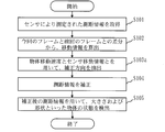
- FIG. 1 is a configuration diagram of a distance measurement correction system according to a first embodiment.
- 3 is a flowchart showing the operation of the distance measurement correction system according to the first embodiment.
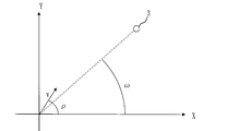
- FIG. FIG. 3 is a diagram showing distance measurement of the sensor according to the first embodiment.
- FIG. 4 is a diagram showing correction of distance measurement information by a distance measurement information correction unit according to the first embodiment.
- FIG. 6 is a configuration diagram of a distance measurement correction system according to a second embodiment.
- FIG. 6 is a flowchart showing the operation of the distance measurement correction system according to the second embodiment.
- FIG. 6 is a diagram showing an example of using sensor movement information according to the second embodiment.
- FIG. 1 is a diagram showing a detection position when a moving object is distance-measured.
- FIG. 2 is a diagram showing data for one frame as data of the same time.
- distance measurement is performed in each direction over a time period from time t1 to time t6.
- FIG. 2 is a diagram showing the result of distance measurement as data at the same time.
- the data adjacent to the distance measurement result in the direction acquired at time t1 is the distance measurement result acquired at time t6. Then, if these distance measurement results are used as they are, the size or shape of the object will not be correct as shown in FIG. Such a phenomenon similarly occurs when the sensor itself moves.
- the distance measurement result for one frame acquired this time and the distance measurement result for the previous frame acquired last time are used to extract the region of the moving object, and the distance measurement results in all directions at the same time are extracted. Will be described and the shape and size of the object will be described.
- FIG. 3 is a configuration diagram of the distance measurement correction system 500 according to the present embodiment.
- Distance measurement correction system 500 includes distance measurement correction device 10 and sensor 1.
- the sensor 1 is specifically a laser sensor such as LiDAR.
- the distance measurement correction device 10 is a computer.
- the distance measurement correction device 10 is an in-vehicle computer in the present embodiment.
- the distance correction device 10 may be a server computer installed in a remote place such as a cloud server.
- a sensor 1 such as LiDAR is mounted on a vehicle on which the distance correction device 10 is mounted.
- the distance correction device 10 is connected to the sensor 1 by wire or wirelessly.
- the distance measurement correction system 500 is also referred to as a LiDAR detection result correction device.
- the distance correction apparatus 10 includes a processor 11 and other hardware such as a memory 12 and an input/output interface 13.
- the processor 11 is connected to other hardware via the signal line 14 and controls these other hardware.
- the distance measurement correction device 10 includes an extraction unit 200 and a correction unit 300 as functional elements.
- the extraction unit 200 includes an acquisition unit 201, a movement calculation unit 202, and a correction direction extraction unit 203.
- the correction unit 300 includes a distance measurement information correction unit 301 and a detection unit 302.
- the functions of the extraction unit 200 and the correction unit 300 are realized by software. Specifically, the functions of the extraction unit 200 and the correction unit 300 are realized by the distance measurement correction program.
- the distance measurement correction program is a program that causes a computer to execute the processing performed by the extraction unit 200 and the correction unit 300 as acquisition processing, movement calculation processing, correction direction extraction processing, distance measurement information correction processing, and detection processing.
- the distance measuring correction method is a method performed by the distance measuring correction system 500 executing a distance measuring correction program.
- the distance correction program may be provided by being recorded in a computer-readable medium, may be provided by being stored in a recording medium or a storage medium, or may be provided as a program product.
- the processor 11 is an IC (Integrated Circuit) that performs arithmetic processing. Specific examples of the processor 11 are a CPU, a DSP, and a GPU.
- the processor 11 is a device that executes a distance measurement correction program.
- CPU is an abbreviation for Central Processing Unit.
- DSP Digital Signal Processor.
- GPU is an abbreviation for Graphics Processing Unit.
- the memory 12 is a device that stores the distance measurement correction program in advance or temporarily.
- a specific example of the memory 12 is RAM, flash memory, or a combination thereof.
- RAM is an abbreviation for Random Access Memory.
- the input/output interface 13 includes a receiver that receives data input to the distance measurement correction program and a transmitter that transmits data output from the distance measurement correction program.
- the input/output interface 13 is a circuit that acquires data from the sensor 1 according to an instruction from the processor 11.
- a specific example of the input/output interface 13 is a communication chip or NIC.
- NIC is an abbreviation for Network Interface Card.
- the distance correction apparatus 10 may further include an input device and a display as hardware.
- the input device is a device operated by a user to input data to the distance measurement correction program.
- a specific example of the input device is a mouse, a keyboard, a touch panel, or some or all of them.
- the display is a device that displays the data output from the distance measurement correction program on the screen.
- a specific example of the display is an LCD. “LCD” is an abbreviation for Liquid Crystal Display.
- the distance measuring correction program is read from the memory 12 into the processor 11 and executed by the processor 11.
- the memory 12 stores not only the distance measurement correction program but also the OS.
- OS is an abbreviation for Operating System.
- the processor 11 executes the ranging correction program while executing the OS. Note that part or all of the distance measurement correction program may be incorporated in the OS.
- the distance correction program and the OS may be stored in the auxiliary storage device. Specific examples of the auxiliary storage device are an HDD, a flash memory, or a combination thereof. “HDD” is an abbreviation for Hard Disk Drive.
- the distance measurement correction device 10 may include a plurality of processors that replace the processor 11.
- the plurality of processors share the execution of the distance measurement correction program.
- a specific example of each processor is a CPU.
- Data, information, signal values, and variable values used, processed, or output by the distance measurement correction program are stored in the memory 12, the auxiliary storage device, or the register or cache memory in the processor 11.
- the data that can be acquired by the input/output interface 13, the calculation result of the distance measurement correction program, the direction time information 15, and the object velocity information 16 are stored in the memory 12.
- the direction time information 15 includes information on the direction of distance measurement of the sensor 1, the order of distance measurement, and time information of each distance measurement.
- the object speed information 16 includes a threshold speed 161 corresponding to the object 3.
- the threshold speed 161 is specifically the maximum speed at which the object 3, which is the object measured by the sensor 1, can move.
- the data and information stored in the memory 12 are input/output in response to a request from the processor 11.
- the distance correction processing by the distance correction system 500 according to the present embodiment is realized by combining the operations of the distance correction apparatus 10 and the sensor 1.
- the distance measurement correction device 10 is the distance measurement information 31 obtained by the sensor 1 measuring one period between the sensor 1 and the object 3 in which at least one of them moves, and the distance measurement correction device 10 detects each of a plurality of directions from the sensor 1 to the object 3.
- the distance measurement information 31, which is the distance in the direction, is corrected.
- the sensor 1 is specifically a laser sensor such as LiDAR.
- FIG. 5 is a diagram showing distance measurement of the sensor 1 according to the present embodiment.
- the sensor 1 emits laser light in a plurality of directions, receives light reflected from the object 3, and calculates the distance to the object. As shown in FIG. 5, the sensor 1 measures the distance m to the obstacle with respect to each angle ( ⁇ , ⁇ ) around the sensor 1.
- step S101 the acquisition unit 201 acquires the distance information from the sensor 1 to the object 3 acquired by the sensor 1 via the input/output interface 13.
- the distance information is the distance from the sensor 1 to the object 3 in each direction.
- the acquisition unit 201 acquires the distance information measured by the sensor 1 in one cycle as the distance measurement information 31. That is, the distance measurement information 31 is distance information for one frame.
- the acquisition unit 201 acquires the distance measurement information 31 for one frame measured this time and the distance measurement information 31 for the previous frame measured last time.
- the distance measurement information 31 acquired by the acquisition unit 201 is stored in the memory 12.
- the acquisition unit 201 acquires, from the memory 12, the distance measurement information for the previous frame measured last time.
- step S ⁇ b>102 the movement calculation unit 202 detects the sensor 1 in each of a plurality of directions based on the difference between the distance measurement information 31 currently measured by the sensor 1 and the distance measurement information previously measured by the sensor 1.
- the movement distance of the object 3 is calculated as the movement information 32.
- the movement calculation unit 202 uses the data of the previous frame and the latest frame, that is, the data of the frame acquired by the sensor 1 this time to move the difference in the distance information in each direction of the latest frame. Calculate as distance. Then, the movement calculation unit 202 calculates the movement distance in each direction of the latest frame as the movement information 32.
- the data of the closest frame in the previous frame is used to create the previous frame data in the same direction as the latest frame.
- the movement information 32 in each direction of the latest frame is calculated.
- the correction direction extraction unit 203 calculates the moving speed of the object 3 as the object moving speed using the moving information 32 in each of the plurality of directions.
- the correction direction extraction unit 203 extracts, as the correction direction 33, the direction in which the distance measurement information 31 is corrected from the plurality of directions based on the object moving speed.
- the correction direction extraction unit 203 extracts each direction of the plurality of directions as the correction direction 33 when the object moving speed in each of the plurality of directions is equal to or less than the threshold calculated based on the threshold speed 161. Extracting the correction direction 33 corresponds to extracting an area in which the distance measurement information 31 is corrected.
- the correction direction extraction unit 203 uses the movement information in each direction to obtain an area in which the distance measurement information 31 is corrected.
- the correction processing is not performed for a stationary object because there is little variation in distance measurement due to a minute time within one frame.
- the difference in distance information becomes large. This is also the case when the latest frame and the previous frame are reversed.
- the moving speed of the object that is assumed according to the usage situation is used as a threshold value, and a direction that has a variation amount and is equal to or less than the threshold value is extracted.
- the threshold value is calculated using the object speed information 16 and the moving speed of the sensor 1 and the threshold speed 161 of the object 3, which is assumed in the space where the sensor 1 is present, that is, the maximum speed.
- the object speed information 16 stores a threshold speed 161 that is the maximum speed that the object 3 can take.
- FIG. 6 is a diagram showing correction of distance measurement information by distance measurement information correction unit 301 according to the present embodiment.
- the distance measurement information correction unit 301 detects the distance from the sensor 1 to the object at the correction time point t between the time point ta0 measured by the sensor 1 in the correction direction 33 and the time point ta1 measured by the sensor 1 this time. The distance A is calculated. Then, the distance measurement information correction unit 301 sets the distance A as the corrected distance measurement information 34. Specifically, the distance measurement information correction unit 301 detects the correction direction of the plurality of directions, that is, the area extracted by the extraction unit 200 from the sensor 1 in each direction with respect to the correction time point t which is an arbitrary time. Find distance information. As shown in FIG.
- the detection unit 302 detects the state of the object 3 using the corrected distance measurement information 34.
- the state of the object 3 is information such as the size and shape of the object.
- the detection unit 302 uses the angle ( ⁇ , ⁇ ) that is the information obtained from the sensor of the distance measurement information for the size of the object to develop the moving speed on the two-dimensional array, Regions having similar values may be grouped as one object.
- the detection unit 302 may plot the corrected distance measurement information and the direction in a three-dimensional space, and create an object with the point groups existing at a short distance as one group. Then, the detection unit 302 obtains the size of the object and shape information such as flatness or curvature from the grouped data.
- the distance measurement correction device is a device that handles distance measurement information output by a sensor.
- the extraction unit compares the distance measurement information from the sensor to the obstacle in each direction with the distance measurement information of the previous frame, calculates the amount of change, and extracts a region for correcting the distance measurement information.
- the correction unit calculates distance measurement information in each direction at the same time in the extracted region, and obtains the shape and size of the object.
- the extraction unit also has a function of setting a threshold value for determining that the object is moving, by using the maximum speed information of the object that is the object of distance measurement.
- the distance measurement correction system uses the latest frame data and the previous frame data acquired by the sensor, and extracts the moving region of the object from the amount of change in the distance information in each direction. Then, the distance measurement correction system according to the present embodiment corrects the distance measurement information for the moving area. Therefore, according to the distance measurement correction system according to the present embodiment, the distance measurement information can be corrected with high accuracy, and the state of the object such as the size and shape of the object can be detected with high accuracy.
- the functions of the extraction unit 200 and the correction unit 300 are realized by software.
- the functions of the extraction unit 200 and the correction unit 300 may be realized by hardware.
- the distance measurement correction device 10 includes an electronic circuit instead of the processor 11.
- the electronic circuit is a dedicated electronic circuit that realizes the functions of the extraction unit 200 and the correction unit 300.
- the electronic circuit is specifically a single circuit, a composite circuit, a programmed processor, a parallel programmed processor, a logic IC, a GA, an ASIC, or an FPGA.
- GA is an abbreviation for Gate Array.
- ASIC is an abbreviation for Application Specific Integrated Circuit.
- FPGA is an abbreviation for Field-Programmable Gate Array.
- the functions of the extraction unit 200 and the correction unit 300 may be realized by one electronic circuit or may be realized by being dispersed in a plurality of electronic circuits. As another modification, some functions of the extraction unit 200 and the correction unit 300 may be realized by an electronic circuit, and the remaining functions may be realized by software. Further, some or all of the functions of the extraction unit 200 and the correction unit 300 may be implemented by firmware.
- Each of the processor and electronic circuit is also called a processing circuit. That is, in the distance measurement correction device 10, the functions of the extraction unit 200 and the correction unit 300 are realized by the processing circuitry.
- Embodiment 2 points different from the first embodiment will be mainly described. The same components as those in the first embodiment are designated by the same reference numerals and the description thereof may be omitted.
- the threshold value is defined based on the object velocity information 16 when the area for correcting the distance measurement information is extracted. In the present embodiment, the threshold is defined using the object velocity information 16 and the movement information of the sensor 1.
- FIG. 7 is a configuration diagram of the distance measurement correction system 500a according to the present embodiment.
- the distance measurement correction system 500a according to the present embodiment includes a sensor information storage device 2 in addition to the configuration of the distance measurement correction system 500 according to the first embodiment.
- the sensor information storage device 2 is connected to the distance measurement correction device 10 via the input/output interface 13.
- the sensor information storage device 2 stores the sensor movement information 21 including the movement speed of the sensor 1 and the movement direction of the sensor 1.
- step S103a the correction direction extraction unit 203a determines the correction directions from the plurality of directions based on the object movement speed in each of the plurality of directions and the sensor movement information 21 including the sensor movement speed and the sensor movement direction. Extract 33. Further, the sensor movement information 21 may include information on the position where the sensor 1 is present.
- FIG. 9 is a diagram showing a usage example of the sensor movement information 21 according to the present embodiment.
- the correction direction extraction unit 203a adjusts the threshold value used when obtaining the correction direction for correcting the distance measurement information 31 according to the sensor movement information 21 and the position where the sensor 1 is present.
- the sensor movement information 21 includes the movement direction of the sensor 1 and the movement speed of the sensor 1. Specifically, as shown in FIG. 9, when the sensor 1 is moving at the speed v and the angle ⁇ , the correction direction extraction unit 203a subtracts v*cos( ⁇ ) from the threshold value.
- the information on the position where the sensor 1 exists is, specifically, information on whether the sensor 1 exists on an ordinary road or whether the sensor 1 exists on an expressway.
- the threshold speed 161 of the object 3 is set to 80 km/h.
- the threshold speed 161 is set to 100 km/h.
- the information on the position where the sensor 1 exists is used for switching the threshold speed 161 of the object 3, that is, the maximum speed.
- steps S104 and S105 are the same as that of the first embodiment.
- the extraction unit has a function of using the movement information and the position information of the sensor to extract the area in which the distance measurement information is corrected.
- the correction unit calculates distance measurement information in each direction for the same time in the extracted region, and obtains the state of the object such as the shape and size of the object. Therefore, according to the distance measurement correction device according to the present embodiment, it is possible to adjust the threshold value used for extracting the area for correcting the distance measurement information according to the movement information of the sensor or the position where the sensor is present. Therefore, the distance measurement correction device according to the present embodiment can correct the distance measurement information with higher accuracy.
- each part of the distance measuring correction device has been described as an independent functional block.
- the configuration of the distance measurement correction device does not have to be the configuration of the above-described embodiment.
- the functional block of the distance correction device may have any configuration as long as it can realize the functions described in the above-described embodiments.
- the distance correction device may be a system including a plurality of devices instead of one device.
- a plurality of parts of the first and second embodiments may be combined and carried out.
- one of these embodiments may be implemented.
- these embodiments may be implemented in whole or in part in any combination. That is, in the first and second embodiments, it is possible to freely combine the respective embodiments, modify any constituent element of each embodiment, or omit any constituent element in each embodiment.
Landscapes
- Engineering & Computer Science (AREA)
- Physics & Mathematics (AREA)
- Computer Networks & Wireless Communication (AREA)
- General Physics & Mathematics (AREA)
- Radar, Positioning & Navigation (AREA)
- Remote Sensing (AREA)
- Electromagnetism (AREA)
- Optical Radar Systems And Details Thereof (AREA)
- Radar Systems Or Details Thereof (AREA)
Abstract
測距補正装置(10)は、センサ(1)と物体との間の測距情報(31)を補正する。移動算出部(202)は、センサ(1)により今回測定された測距情報(31)と、センサ(1)により前回測定された測距情報との差分に基づいて、複数の方向の各方向におけるセンサ(1)に対する物体の移動距離を移動情報(32)として算出する。補正方向抽出部(203)は、複数の方向の各方向における移動情報(32)を用いて物体の移動速度を物体移動速度として算出し、物体移動速度に基づいて、複数の方向から、測距情報(31)を補正する方向を補正方向(33)として抽出する。測距情報補正部(301)は、補正方向(33)において、センサ(1)が前回測定した時点とセンサが今回測位した時点との間の補正時点における、センサ(1)から物体までの距離を補正後の測距情報(34)として算出する。
Description
本発明は、測距補正装置、測距補正システム、測距補正方法、および測距補正プログラムに関する。
特許文献1には、ビーム状の光を走査して走査面に画像を形成する二次元光走査装置が開示されている。特許文献1の二次元光走査装置は、光源から出射された光を、交差する2軸方向に偏向走査する偏光器と、交差する2軸方向の偏向角度を所定の周波数および振幅で変化させる制御手段とを有する。
LiDAR(Laser Imaging Detection and Ranging)といったセンサは、パルス状に発光するレーザー照射に対する散乱光を測定し、遠距離にある物体までの距離、あるいは、その物体の性質を分析するために用いられる。LiDARといったセンサにおいて、従来技術の機構により振幅および位相を制御して各方向に対する距離を算出する場合、被写体である物体が移動していると、隣接した方向の測距結果が隣接した時刻の測距結果ではない場合がある。そして、このような測距結果をそのまま利用すると、物体の大きさあるいは形状といった検出結果が正しくないものとなってしまう。
本発明は、センサによる測距情報を用いた物体の検出の精度を向上させることを目的とする。
本発明に係る測距補正装置は、少なくともいずれかが移動するセンサと物体との間を前記センサが1周期で測定した測距情報であって、前記センサから前記物体までの複数の方向の各方向における距離である測距情報を補正する測距補正装置において、
前記センサにより今回測定された測距情報と、前記センサにより前回測定された測距情報との差分に基づいて、前記複数の方向の各方向における前記センサに対する前記物体の移動距離を移動情報として算出する移動算出部と、
前記複数の方向の各方向における移動情報を用いて前記物体の移動速度を物体移動速度として算出し、前記物体移動速度に基づいて、前記複数の方向から、前記測距情報を補正する方向を補正方向として抽出する補正方向抽出部と、
前記補正方向において、前記センサが前回測定した時点と前記センサが今回測位した時点との間の補正時点における、前記センサから前記物体までの距離を算出し、補正後の測距情報とする測距情報補正部とを備えた。
本発明に係る測距補正装置では、補正方向抽出部が、センサから物体までの複数の方向のうち、物体を捉えている方向を補正方向として抽出する。測距情報補正部は、補正方向において、センサが前回測定した時点とセンサが今回測位した時点との間の補正時点における、センサから物体までの距離を算出し、補正後の測距情報とする。よって、本発明に係る測距補正装置によれば、センサによる測距情報を用いた物体の検出の精度を向上させることができる。
以下、本発明の実施の形態について、図を用いて説明する。なお、各図中、同一または相当する部分には、同一符号を付している。実施の形態の説明において、同一または相当する部分については、説明を適宜省略または簡略化する。
実施の形態1.
***構成の説明***
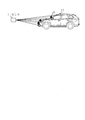
図1は、移動物体を測距した場合の検出位置を示す図である。また、図2は、1フレーム分のデータを同一時間のデータとして表した図である。
図1では、センサ1により1フレーム分のデータを取得するために、時刻t1からt6の時間をかけてそれぞれの方向について測距している。図2は、測距した結果を同一時間のデータとして表した図である。
***構成の説明***
図1は、移動物体を測距した場合の検出位置を示す図である。また、図2は、1フレーム分のデータを同一時間のデータとして表した図である。
図1では、センサ1により1フレーム分のデータを取得するために、時刻t1からt6の時間をかけてそれぞれの方向について測距している。図2は、測距した結果を同一時間のデータとして表した図である。
図2に示すように、時刻t1に取得した方向の測距結果に隣接するデータは、時刻t6に取得した測距結果となる。そして、これらの測距結果をそのまま利用すると、図2に示すように物体の大きさあるいは形状が正しいものとならなくなる。このような現象は、センサそのものが移動した場合についても同様に発生する。
本実施の形態では、今回取得した1フレーム分の測距結果と、前回取得した前フレーム分の測距結果とを利用し、移動物体の領域を抽出し、同一時刻における全方向の測距結果を算出し、物体の形状および大きさを検出する態様について説明する。
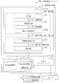
図3は、本実施の形態に係る測距補正システム500の構成図である。
本実施の形態に係る測距補正システム500は、測距補正装置10とセンサ1を備える。センサ1は、具体的には、LiDARといったレーザーセンサである。
また、測距補正装置10は、コンピュータである。測距補正装置10は、本実施の形態では車載コンピュータである。しかし、測距補正装置10は、クラウドサーバといった遠隔地に設置されたサーバコンピュータでもよい。測距補正装置10が搭載されている車両には、LiDARといったセンサ1が搭載されている。測距補正装置10は、センサ1と有線または無線で接続されている。
測距補正システム500は、LiDAR検出結果補正装置ともいう。
本実施の形態に係る測距補正システム500は、測距補正装置10とセンサ1を備える。センサ1は、具体的には、LiDARといったレーザーセンサである。
また、測距補正装置10は、コンピュータである。測距補正装置10は、本実施の形態では車載コンピュータである。しかし、測距補正装置10は、クラウドサーバといった遠隔地に設置されたサーバコンピュータでもよい。測距補正装置10が搭載されている車両には、LiDARといったセンサ1が搭載されている。測距補正装置10は、センサ1と有線または無線で接続されている。
測距補正システム500は、LiDAR検出結果補正装置ともいう。
測距補正装置10は、プロセッサ11を備えるとともに、メモリ12および入出力インタフェース13といった他のハードウェアを備える。プロセッサ11は、信号線14を介して他のハードウェアと接続され、これら他のハードウェアを制御する。
測距補正装置10は、機能要素として、抽出部200と、補正部300を備える。抽出部200は、取得部201と、移動算出部202と、補正方向抽出部203を備える。補正部300は、測距情報補正部301と、検出部302を備える。抽出部200と補正部300の機能は、ソフトウェアにより実現される。具体的には、抽出部200と補正部300の機能は、測距補正プログラムにより実現される。測距補正プログラムは、抽出部200と補正部300により行われる処理を、取得処理と移動算出処理と補正方向抽出処理と測距情報補正処理と検出処理としてコンピュータに実行させるプログラムである。また、測距補正方法は、測距補正システム500が測距補正プログラムを実行することにより行われる方法である。測距補正プログラムは、コンピュータ読取可能な媒体に記録されて提供されてもよいし、記録媒体あるいは記憶媒体に格納されて提供されてもよいし、プログラムプロダクトとして提供されてもよい。
プロセッサ11は、演算処理を行うIC(Integrated Circuit)である。プロセッサ11の具体例は、CPU、DSP、GPUである。プロセッサ11は、測距補正プログラムを実行する装置である。「CPU」は、Central Processing Unitの略語である。「DSP」は、Digital Signal Processorの略語である。「GPU」は、Graphics Processing Unitの略語である。
メモリ12は、測距補正プログラムを予めまたは一時的に記憶する装置である。メモリ12の具体例は、RAM、フラッシュメモリまたはこれらの組み合わせである。「RAM」は、Random Access Memoryの略語である。
入出力インタフェース13は、測距補正プログラムに入力されるデータを受信するレシーバと、測距補正プログラムから出力されるデータを送信するトランスミッタとを備える。入出力インタフェース13は、プロセッサ11からの指示に従ってセンサ1よりデータを取得する回路である。入出力インタフェース13の具体例は、通信チップまたはNICである。「NIC」は、Network Interface Cardの略語である。
測距補正装置10は、ハードウェアとして、入力機器と、ディスプレイとをさらに備えてもよい。入力機器は、測距補正プログラムへのデータの入力のためにユーザにより操作される機器である。入力機器の具体例は、マウス、キーボード、タッチパネル、または、これらのうちいくつか、もしくは、すべての組み合わせである。ディスプレイは、測距補正プログラムから出力されるデータを画面に表示する機器である。ディスプレイの具体例は、LCDである。「LCD」は、Liquid Crystal Displayの略語である。
測距補正装置10は、ハードウェアとして、入力機器と、ディスプレイとをさらに備えてもよい。入力機器は、測距補正プログラムへのデータの入力のためにユーザにより操作される機器である。入力機器の具体例は、マウス、キーボード、タッチパネル、または、これらのうちいくつか、もしくは、すべての組み合わせである。ディスプレイは、測距補正プログラムから出力されるデータを画面に表示する機器である。ディスプレイの具体例は、LCDである。「LCD」は、Liquid Crystal Displayの略語である。
測距補正プログラムは、メモリ12からプロセッサ11に読み込まれ、プロセッサ11によって実行される。メモリ12には、測距補正プログラムだけでなく、OSも記憶されている。「OS」は、Operating Systemの略語である。プロセッサ11は、OSを実行しながら、測距補正プログラムを実行する。なお、測距補正プログラムの一部または全部がOSに組み込まれていてもよい。
測距補正プログラムおよびOSは、補助記憶装置に記憶されていてもよい。補助記憶装置はの具体例は、HDD、フラッシュメモリまたはこれらの組み合わせである。「HDD」は、Hard Disk Driveの略語である。測距補正プログラムおよびOSは、補助記憶装置に記憶されている場合、メモリ12にロードされ、プロセッサ11によって実行される。
測距補正プログラムおよびOSは、補助記憶装置に記憶されていてもよい。補助記憶装置はの具体例は、HDD、フラッシュメモリまたはこれらの組み合わせである。「HDD」は、Hard Disk Driveの略語である。測距補正プログラムおよびOSは、補助記憶装置に記憶されている場合、メモリ12にロードされ、プロセッサ11によって実行される。
測距補正装置10は、プロセッサ11を代替する複数のプロセッサを備えていてもよい。これら複数のプロセッサは、測距補正プログラムの実行を分担する。それぞれのプロセッサの具体例は、CPUである。
測距補正プログラムにより利用、処理または出力されるデータ、情報、信号値および変数値は、メモリ12、補助記憶装置、または、プロセッサ11内のレジスタまたはキャッシュメモリに記憶される。特に、入出力インタフェース13で取得できるデータ、測距補正プログラムの算出結果、方向時間情報15、および物体速度情報16は、メモリ12に記憶される。方向時間情報15には、センサ1の測距する方向の情報、測距する順序、および各測距の時間情報が含まれている。物体速度情報16には、物体3に対応する閾値速度161が含まれる。閾値速度161は、具体的には、センサ1が計測する対象物である物体3が移動し得る最大速度である。メモリ12に記憶されたデータおよび情報は、プロセッサ11からの要求に応じて入出力される。
***動作の説明***
図4を用いて、本実施の形態に係る測距補正システム500の動作について説明する。
本実施の形態に係る測距補正システム500による測距補正処理は、測距補正装置10とセンサ1の動作を組み合わせることによって実現される。
測距補正装置10は、少なくともいずれかが移動するセンサ1と物体3との間をセンサ1が1周期で測定した測距情報31であって、センサ1から物体3までの複数の方向の各方向における距離である測距情報31を補正する。
センサ1は、具体的には、LiDARといったレーザーセンサである。
図4を用いて、本実施の形態に係る測距補正システム500の動作について説明する。
本実施の形態に係る測距補正システム500による測距補正処理は、測距補正装置10とセンサ1の動作を組み合わせることによって実現される。
測距補正装置10は、少なくともいずれかが移動するセンサ1と物体3との間をセンサ1が1周期で測定した測距情報31であって、センサ1から物体3までの複数の方向の各方向における距離である測距情報31を補正する。
センサ1は、具体的には、LiDARといったレーザーセンサである。
図5は、本実施の形態に係るセンサ1の測距を示す図である。
センサ1は、複数の方向にレーザーを照射し、物体3から反射してくる光を受光し、物体までの距離を算出する。センサ1は、図5に示すように、センサ1を中心に、各角度(θ,ω)に対する障害物までの距離mを計測する。
センサ1は、複数の方向にレーザーを照射し、物体3から反射してくる光を受光し、物体までの距離を算出する。センサ1は、図5に示すように、センサ1を中心に、各角度(θ,ω)に対する障害物までの距離mを計測する。
ステップS101において、取得部201は、入出力インタフェース13を介して、センサ1により取得されたセンサ1から物体3までの距離情報を取得する。距離情報は、各方向に対するセンサ1から物体3までの距離である。取得部201は、センサ1により1周期で測定された距離情報を測距情報31として取得する。つまり、測距情報31は、1フレーム分の距離情報である。
取得部201は、今回測定された1フレーム分の測距情報31と、前回測定された前フレーム分の測距情報とを取得する。なお、取得部201により取得された測距情報31は、メモリ12に記憶されている。取得部201は、前回測定された前フレーム分の測距情報を、メモリ12から取得する。
取得部201は、今回測定された1フレーム分の測距情報31と、前回測定された前フレーム分の測距情報とを取得する。なお、取得部201により取得された測距情報31は、メモリ12に記憶されている。取得部201は、前回測定された前フレーム分の測距情報を、メモリ12から取得する。
ステップS102において、移動算出部202は、センサ1により今回測定された測距情報31と、センサ1により前回測定された測距情報との差分に基づいて、複数の方向の各方向におけるセンサ1に対する物体3の移動距離を移動情報32として算出する。
具体的には、移動算出部202は、前フレームのデータと、最新のフレーム、すなわち今回センサ1により取得されたフレームのデータとを利用して、最新フレームの各方向に対する距離情報の差分を移動距離として求める。そして、移動算出部202は、最新フレームの各方向に対する移動距離を移動情報32として算出する。なお、最新フレームのデータの計測方向と前フレームのデータの計測方向とが同一でない場合は、前フレームにおける最近接方向のデータを利用して、最新フレームと同一方向の前フレームのデータを作成し、最新フレームの各方向の移動情報32を算出する。
具体的には、移動算出部202は、前フレームのデータと、最新のフレーム、すなわち今回センサ1により取得されたフレームのデータとを利用して、最新フレームの各方向に対する距離情報の差分を移動距離として求める。そして、移動算出部202は、最新フレームの各方向に対する移動距離を移動情報32として算出する。なお、最新フレームのデータの計測方向と前フレームのデータの計測方向とが同一でない場合は、前フレームにおける最近接方向のデータを利用して、最新フレームと同一方向の前フレームのデータを作成し、最新フレームの各方向の移動情報32を算出する。
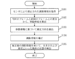
ステップS103において、補正方向抽出部203は、複数の方向の各方向における移動情報32を用いて物体3の移動速度を物体移動速度として算出する。補正方向抽出部203は、物体移動速度に基づいて、複数の方向から、測距情報31を補正する方向を補正方向33として抽出する。補正方向抽出部203は、複数の方向の各方向における物体移動速度が、閾値速度161に基づいて算出された閾値以下の場合に、複数の方向の各方向を補正方向33として抽出する。補正方向33を抽出することは、測距情報31を補正する領域を抽出することに相当する。
具体的には、補正方向抽出部203は、各方向の移動情報を利用し、測距情報31を補正する領域を求める。静止物に関しては、1フレーム内の微小時間による測距変動が少ないため、補正処理を行わない。一方で、最新フレームでは障害物を測距しているが、前フレームでは別の遠方の物体を計測している場合は、距離情報の差分が大きくなる。これは、最新フレームと前フレームで逆の場合も同様である。このとき、最新フレームのデータと前フレームのデータを利用して、任意の時間の測距情報を作成しても、正しい情報にはならない。そこで、利用状況に応じて想定される物体の移動速度を閾値として、変動量があり、かつ、閾値以下となる方向を抽出する。なお、閾値は、物体速度情報16を用いて、センサ1の移動速度と、センサ1が存在する空間において想定される物体3の閾値速度161、すなわち最大速度とを利用して算出される。物体速度情報16には、物体3の取り得る最大速度である閾値速度161が格納されている。
具体的には、補正方向抽出部203は、各方向の移動情報を利用し、測距情報31を補正する領域を求める。静止物に関しては、1フレーム内の微小時間による測距変動が少ないため、補正処理を行わない。一方で、最新フレームでは障害物を測距しているが、前フレームでは別の遠方の物体を計測している場合は、距離情報の差分が大きくなる。これは、最新フレームと前フレームで逆の場合も同様である。このとき、最新フレームのデータと前フレームのデータを利用して、任意の時間の測距情報を作成しても、正しい情報にはならない。そこで、利用状況に応じて想定される物体の移動速度を閾値として、変動量があり、かつ、閾値以下となる方向を抽出する。なお、閾値は、物体速度情報16を用いて、センサ1の移動速度と、センサ1が存在する空間において想定される物体3の閾値速度161、すなわち最大速度とを利用して算出される。物体速度情報16には、物体3の取り得る最大速度である閾値速度161が格納されている。
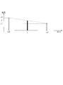
図6は、本実施の形態に係る測距情報補正部301による測距情報の補正を示す図である。
ステップS104において、測距情報補正部301は、補正方向33において、センサ1が前回測定した時点ta0と、センサ1が今回測位した時点ta1との間の補正時点tにおける、センサ1から物体までの距離Aを算出する。そして、測距情報補正部301は、その距離Aを補正後の測距情報34とする。
具体的には、測距情報補正部301は、複数の方向のうちの補正方向について、すなわち抽出部200により抽出された領域について、任意の時間である補正時点tに対する各方向のセンサ1からの距離情報を求める。図6に示すように、前フレームと最新フレームの同一方向の測距結果をa0,a1とする。また、それぞれの測距時間をta0,ta1とする。このとき、時刻tの補正後の距離Aは以下の式1で計算できる。
(式1)A=a0+(a1-a0)*(t-ta0)/(ta1-ta0)
ステップS105において、検出部302は、補正後の測距情報34を用いて、物体3の状態を検出する。物体3の状態とは、物体の大きさおよび形状といった情報である。検出部302は、具体的には、物体の大きさについては、測距情報のセンサからの取得情報である角度(θ,ω)を利用して、移動速度を2次元配列上に展開し、隣接した値で類似した領域を1つの物体としてグルーピングしても良い。また、検出部302は、補正した測距情報と方向から3次元空間にプロットし、近距離に存在する点群を1つのグループとして物体を作成しても良い。そして、検出部302は、グルーピングしたデータから物体の大きさ、および、平面度あるいは曲率といった形状情報を求める。
***本実施の形態の効果の説明***
本実施の形態に係る測距補正装置は、センサが出力する測距情報を扱う装置である。抽出部は、センサから各方向に対する障害物までの測距情報を、前フレームの測距情報と比較して変化量を算出し、測距情報を補正する領域を抽出する。補正部は、抽出した領域において同一時間の各方向の測距情報を算出し、物体の形状および大きさを求める。また、抽出部は、測距の対象となる物体の最高速度情報を利用して、物体が移動していると判断する閾値を設定する機能を備える。
以上のように、本実施の形態に係る測距補正システムでは、センサで取得した最新フレームと前フレームのデータを利用し、各方向の距離情報の変化量から物体の移動領域を抽出する。そして、本実施の形態に係る測距補正システムでは、その移動領域に対して、測距情報の補正をする。よって、本実施の形態に係る測距補正システムによれば、測距情報の補正を高精度で実行することができ、物体の大きさおよび形状といった物体の状態を精度良く検出できるようになる。
***他の構成***
<変形例1>
本実施の形態では、抽出部200と補正部300の機能がソフトウェアで実現される。変形例として、抽出部200と補正部300の機能がハードウェアで実現されてもよい。具体的には、測距補正装置10は、プロセッサ11に替えて電子回路を備える。
<変形例1>
本実施の形態では、抽出部200と補正部300の機能がソフトウェアで実現される。変形例として、抽出部200と補正部300の機能がハードウェアで実現されてもよい。具体的には、測距補正装置10は、プロセッサ11に替えて電子回路を備える。
電子回路は、抽出部200と補正部300の機能を実現する専用の電子回路である。
電子回路は、具体的には、単一回路、複合回路、プログラム化したプロセッサ、並列プログラム化したプロセッサ、ロジックIC、GA、ASIC、または、FPGAである。「GA」は、Gate Arrayの略語である。「ASIC」は、Application Specific Integrated Circuitの略語である。「FPGA」は、Field-Programmable Gate Arrayの略語である。
抽出部200と補正部300の機能は、1つの電子回路で実現されてもよいし、複数の電子回路に分散して実現されてもよい。
別の変形例として、抽出部200と補正部300の一部の機能が電子回路で実現され、残りの機能がソフトウェアで実現されてもよい。また、抽出部200と補正部300の一部またはすべての機能がファームウェアで実現されてもよい。
プロセッサと電子回路の各々は、プロセッシングサーキットリとも呼ばれる。つまり、測距補正装置10において、抽出部200と補正部300の機能は、プロセッシングサーキットリにより実現される。
実施の形態2.
本実施の形態では、主に、実施の形態1と異なる点について説明する。なお、実施の形態1と同様の構成には同一の符号を付し、その説明を省略する場合がある。
実施の形態1では、測距情報を補正する領域を抽出する際に、物体速度情報16をもとに閾値を定義した。本実施の形態では、物体速度情報16と、センサ1の移動情報とを利用して閾値を定義する。
本実施の形態では、主に、実施の形態1と異なる点について説明する。なお、実施の形態1と同様の構成には同一の符号を付し、その説明を省略する場合がある。
実施の形態1では、測距情報を補正する領域を抽出する際に、物体速度情報16をもとに閾値を定義した。本実施の形態では、物体速度情報16と、センサ1の移動情報とを利用して閾値を定義する。
***構成の説明***
図7は、本実施の形態に係る測距補正システム500aの構成図である。
本実施の形態に係る測距補正システム500aは、実施の形態1の測距補正システム500の構成に加えて、センサ情報格納装置2を備える。センサ情報格納装置2は、入出力インタフェース13を介して、測距補正装置10と接続される。
図7は、本実施の形態に係る測距補正システム500aの構成図である。
本実施の形態に係る測距補正システム500aは、実施の形態1の測距補正システム500の構成に加えて、センサ情報格納装置2を備える。センサ情報格納装置2は、入出力インタフェース13を介して、測距補正装置10と接続される。
センサ情報格納装置2は、センサ1の移動速度とセンサ1の移動方向とを含むセンサ移動情報21を格納する。
***動作の説明***
図8を用いて、本実施の形態に係る測距補正システム500aの動作について説明する。
ステップS101とステップS102の処理は、実施の形態1と同様である。
図8を用いて、本実施の形態に係る測距補正システム500aの動作について説明する。
ステップS101とステップS102の処理は、実施の形態1と同様である。
ステップS103aにおいて、補正方向抽出部203aは、複数の方向の各方向における物体移動速度と、センサの移動速度とセンサの移動方向とを含むセンサ移動情報21とに基づいて、複数の方向から補正方向33を抽出する。また、センサ移動情報21には、センサ1が存在する位置の情報が含まれていてもよい。
図9は、本実施の形態に係るセンサ移動情報21の利用例を示す図である。
補正方向抽出部203aは、測距情報31を補正する補正方向を求める際に用いられる閾値を、センサ移動情報21とセンサ1が存在する位置に応じて調整する。センサ移動情報21には、センサ1の移動方向とセンサ1の移動速度が含まれる。
具体的には、図9に示すようにセンサ1が速度vかつ角度ρで移動中の場合、補正方向抽出部203aは、閾値にv*cos(ρ-ω)を減算する。
また、センサ1が存在する位置の情報は、具体的には、センサ1が一般道に存在するか、あるいは、センサ1が高速道路に存在するかといった情報である。具体的には、一般道にセンサ1が存在する場合は物体3の閾値速度161を80km/hとする。また、高速道路上にセンサが存在する場合は閾値速度161を100km/hとする。このように、センサ1が存在する位置の情報は、物体3の閾値速度161、すなわち最大速度の切り替えに用いられる。
ステップS104とステップS105の処理は、実施の形態1と同様である。
***本実施の形態の効果の説明***
本実施の形態に係る測距補正装置は、抽出部が、センサの移動情報および位置情報を利用し、測距情報を補正する領域を抽出する機能を有する。補正部は、抽出した領域において同一時間の各方向の測距情報を算出し、物体の形状および大きさといった物体の状態を求める。よって、本実施の形態に係る測距補正装置によれば、センサの移動情報あるいはセンサが存在する位置に応じて、測距情報を補正する領域の抽出に利用する閾値を調整できる。したがって、本実施の形態に係る測距補正装置によれば、より精度良く測距情報を補正することができる。
本実施の形態に係る測距補正装置は、抽出部が、センサの移動情報および位置情報を利用し、測距情報を補正する領域を抽出する機能を有する。補正部は、抽出した領域において同一時間の各方向の測距情報を算出し、物体の形状および大きさといった物体の状態を求める。よって、本実施の形態に係る測距補正装置によれば、センサの移動情報あるいはセンサが存在する位置に応じて、測距情報を補正する領域の抽出に利用する閾値を調整できる。したがって、本実施の形態に係る測距補正装置によれば、より精度良く測距情報を補正することができる。
以上の実施の形態1,2では、測距補正装置の各部を独立した機能ブロックとして説明した。しかし、測距補正装置の構成は、上述した実施の形態のような構成でなくてもよい。測距補正装置の機能ブロックは、上述した実施の形態で説明した機能を実現することができれば、どのような構成でもよい。また、測距補正装置は、1つの装置でなく、複数の装置から構成されたシステムでもよい。
また、実施の形態1,2のうち、複数の部分を組み合わせて実施しても構わない。あるいは、これらの実施の形態のうち、1つの部分を実施しても構わない。その他、これら実施の形態を、全体としてあるいは部分的に、どのように組み合わせて実施しても構わない。
すなわち、実施の形態1,2では、各実施の形態の自由な組み合わせ、あるいは各実施の形態の任意の構成要素の変形、もしくは各実施の形態において任意の構成要素の省略が可能である。
また、実施の形態1,2のうち、複数の部分を組み合わせて実施しても構わない。あるいは、これらの実施の形態のうち、1つの部分を実施しても構わない。その他、これら実施の形態を、全体としてあるいは部分的に、どのように組み合わせて実施しても構わない。
すなわち、実施の形態1,2では、各実施の形態の自由な組み合わせ、あるいは各実施の形態の任意の構成要素の変形、もしくは各実施の形態において任意の構成要素の省略が可能である。
なお、上述した実施の形態は、本質的に好ましい例示であって、本発明の範囲、本発明の適用物の範囲、および本発明の用途の範囲を制限することを意図するものではない。上述した実施の形態は、必要に応じて種々の変更が可能である。
1 センサ、2 センサ情報格納装置、3 物体、10 測距補正装置、11 プロセッサ、12 メモリ、13 入出力インタフェース、14 信号線、15 方向時間情報、16 物体速度情報、21 センサ移動情報、31 測距情報、32 移動情報、33 補正方向、34 補正後の測距情報、161 閾値速度、200 抽出部、201 取得部、202 移動算出部、203,203a 補正方向抽出部、300 補正部、301 測距情報補正部、302 検出部、500,500a 測距補正システム。
Claims (8)
- 少なくともいずれかが移動するセンサと物体との間の測距情報であって、前記センサが1周期で測定した前記センサから前記物体までの複数の方向の各方向における距離である測距情報を補正する測距補正装置において、
前記センサにより今回測定された測距情報と、前記センサにより前回測定された測距情報との差分に基づいて、前記複数の方向の各方向における前記センサに対する前記物体の移動距離を移動情報として算出する移動算出部と、
前記複数の方向の各方向における移動情報を用いて前記物体の移動速度を物体移動速度として算出し、前記物体移動速度に基づいて、前記複数の方向から、前記測距情報を補正する方向を補正方向として抽出する補正方向抽出部と、
前記補正方向において、前記センサが前回測定した時点と前記センサが今回測位した時点との間の補正時点における、前記センサから前記物体までの距離を補正後の測距情報として算出する測距情報補正部と
を備えた測距補正装置。 - 前記測距補正装置は、
前記補正後の測距情報を用いて、前記物体の状態を検出する検出部を備えた請求項1に記載の測距補正装置。 - 前記測距補正装置は、
前記物体に対応する閾値速度を含む物体速度情報をメモリに備え、
前記補正方向抽出部は、
前記複数の方向の各方向における前記物体移動速度が、前記閾値速度に基づいて算出された閾値以下の場合に、前記複数の方向の各方向を前記補正方向として抽出する請求項1または請求項2に記載の測距補正装置。 - 前記測距補正装置は、
前記物体に対応する閾値速度を含む物体速度情報をメモリに備え、
前記補正方向抽出部は、
前記複数の方向の各方向における前記物体移動速度と、前記センサの移動速度と前記センサの移動方向とを含むセンサ移動情報とに基づいて、前記複数の方向から前記補正方向を抽出する請求項1または請求項2に記載の測距補正装置。 - 少なくともいずれかが移動するセンサと物体との間の測距情報であって、前記センサが1周期で測定した前記センサから前記物体までの複数の方向の各方向における距離である測距情報を補正する測距補正装置と、前記センサとを備えた測距補正システムにおいて、
前記測距補正装置は、
前記センサにより今回測定された測距情報と、前記センサにより前回測定された測距情報との差分に基づいて、前記複数の方向の各方向における前記センサに対する前記物体の移動距離を移動情報として算出する移動算出部と、
前記複数の方向の各方向における移動情報を用いて前記物体の移動速度を物体移動速度として算出し、前記物体移動速度に基づいて、前記複数の方向から、前記測距情報を補正する方向を補正方向として抽出する補正方向抽出部と、
前記補正方向において、前記センサが前回測定した時点と前記センサが今回測位した時点との間の補正時点における、前記センサから前記物体までの距離を補正後の測距情報として算出する測距情報補正部と
を備えた測距補正システム。 - 前記測距補正システムは、
前記センサの移動速度と前記センサの移動方向とを含むセンサ移動情報を格納するセンサ情報格納装置を備え、
前記測距補正装置は、
前記物体に対応する閾値速度を含む物体速度情報をメモリに備え、
前記補正方向抽出部は、
前記複数の方向の各方向における前記物体移動速度と、前記センサ情報格納装置に格納された前記センサ移動情報とに基づいて、前記複数の方向から前記補正方向を抽出する請求項5に記載の測距補正システム。 - 少なくともいずれかが移動するセンサと物体との間の測距情報であって、前記センサが1周期で測定した前記センサから前記物体までの複数の方向の各方向における距離である測距情報を補正する測距補正装置の測距補正方法において、
移動算出部が、前記センサにより今回測定された測距情報と、前記センサにより前回測定された測距情報との差分に基づいて、前記複数の方向の各方向における前記センサに対する前記物体の移動距離を移動情報として算出し、
補正方向抽出部が、前記複数の方向の各方向における移動情報を用いて前記物体の移動速度を物体移動速度として算出し、前記物体移動速度に基づいて、前記複数の方向から、前記測距情報を補正する方向を補正方向として抽出し、
測距情報補正部が、前記補正方向において、前記センサが前回測定した時点と前記センサが今回測位した時点との間の補正時点における、前記センサから前記物体までの距離を補正後の測距情報として算出する測距補正方法。 - 少なくともいずれかが移動するセンサと物体との間の測距情報であって、前記センサが1周期で測定した前記センサから前記物体までの複数の方向の各方向における距離である測距情報を補正する測距補正装置の測距補正プログラムにおいて、
前記センサにより今回測定された測距情報と、前記センサにより前回測定された測距情報との差分に基づいて、前記複数の方向の各方向における前記センサに対する前記物体の移動距離を移動情報として算出する移動算出処理と、
前記複数の方向の各方向における移動情報を用いて前記物体の移動速度を物体移動速度として算出し、前記物体移動速度に基づいて、前記複数の方向から、前記測距情報を補正する方向を補正方向として抽出する補正方向抽出処理と、
前記補正方向において、前記センサが前回測定した時点と前記センサが今回測位した時点との間の補正時点における、前記センサから前記物体までの距離を補正後の測距情報として算出する測距情報補正処理と
をコンピュータである前記測距補正装置に実行させる測距補正プログラム。
Priority Applications (5)
| Application Number | Priority Date | Filing Date | Title |
|---|---|---|---|
| DE112018008130.3T DE112018008130T5 (de) | 2018-12-11 | 2018-12-11 | Abstandsmessungs-korrekturvorrichtung, abstandsmessungs-korrektursystem, abstandsmessungs-korrekturverfahren und abstandsmessungs-korrekturprogramm |
| CN201880099451.1A CN113167895B (zh) | 2018-12-11 | 2018-12-11 | 测距校正装置、测距校正系统、测距校正方法和计算机能读取的存储介质 |
| JP2020558836A JP6854986B2 (ja) | 2018-12-11 | 2018-12-11 | 測距補正装置、測距補正システム、測距補正方法、および測距補正プログラム |
| PCT/JP2018/045486 WO2020121403A1 (ja) | 2018-12-11 | 2018-12-11 | 測距補正装置、測距補正システム、測距補正方法、および測距補正プログラム |
| US17/228,003 US12228649B2 (en) | 2018-12-11 | 2021-04-12 | Distance measurement correction device, distance measurement correction system, distance measurement correction method, and computer readable medium |
Applications Claiming Priority (1)
| Application Number | Priority Date | Filing Date | Title |
|---|---|---|---|
| PCT/JP2018/045486 WO2020121403A1 (ja) | 2018-12-11 | 2018-12-11 | 測距補正装置、測距補正システム、測距補正方法、および測距補正プログラム |
Related Child Applications (1)
| Application Number | Title | Priority Date | Filing Date |
|---|---|---|---|
| US17/228,003 Continuation US12228649B2 (en) | 2018-12-11 | 2021-04-12 | Distance measurement correction device, distance measurement correction system, distance measurement correction method, and computer readable medium |
Publications (1)
| Publication Number | Publication Date |
|---|---|
| WO2020121403A1 true WO2020121403A1 (ja) | 2020-06-18 |
Family
ID=71075981
Family Applications (1)
| Application Number | Title | Priority Date | Filing Date |
|---|---|---|---|
| PCT/JP2018/045486 Ceased WO2020121403A1 (ja) | 2018-12-11 | 2018-12-11 | 測距補正装置、測距補正システム、測距補正方法、および測距補正プログラム |
Country Status (5)
| Country | Link |
|---|---|
| US (1) | US12228649B2 (ja) |
| JP (1) | JP6854986B2 (ja) |
| CN (1) | CN113167895B (ja) |
| DE (1) | DE112018008130T5 (ja) |
| WO (1) | WO2020121403A1 (ja) |
Citations (4)
| Publication number | Priority date | Publication date | Assignee | Title |
|---|---|---|---|---|
| JP2005216160A (ja) * | 2004-01-30 | 2005-08-11 | Secom Co Ltd | 画像生成装置、侵入者監視装置及び画像生成方法 |
| JP2016133341A (ja) * | 2015-01-16 | 2016-07-25 | 株式会社リコー | 物体検出装置、センシング装置、移動体装置及び物体検出方法 |
| JP2017044599A (ja) * | 2015-08-27 | 2017-03-02 | ルネサスエレクトロニクス株式会社 | 制御システム |
| US20180031701A1 (en) * | 2016-07-26 | 2018-02-01 | Semiconductor Components Industries, Llc | Obstacle monitoring using motion-compensated distance |
Family Cites Families (11)
| Publication number | Priority date | Publication date | Assignee | Title |
|---|---|---|---|---|
| JP3635166B2 (ja) | 1995-12-27 | 2005-04-06 | 株式会社デンソー | 距離測定方法及び距離測定装置 |
| JP3750512B2 (ja) * | 2000-10-12 | 2006-03-01 | 日産自動車株式会社 | 車両用周辺障害物検出装置 |
| JP4952298B2 (ja) | 2007-02-28 | 2012-06-13 | 株式会社デンソー | 二次元光走査装置 |
| JP4415198B2 (ja) | 2007-08-30 | 2010-02-17 | カシオ計算機株式会社 | 画像合成装置及びプログラム |
| JP5448617B2 (ja) * | 2008-08-19 | 2014-03-19 | パナソニック株式会社 | 距離推定装置、距離推定方法、プログラム、集積回路およびカメラ |
| JP4831441B2 (ja) * | 2010-03-30 | 2011-12-07 | アイシン・エィ・ダブリュ株式会社 | 方位センサの補正係数演算装置及び演算プログラム |
| WO2013072999A1 (ja) * | 2011-11-14 | 2013-05-23 | 富士通株式会社 | 電子装置、携帯端末及び速度計測方法 |
| JP2013156139A (ja) | 2012-01-30 | 2013-08-15 | Ihi Corp | 移動物体検出装置及び移動物体検出方法 |
| JP6147056B2 (ja) | 2013-03-29 | 2017-06-14 | 株式会社メガチップス | 画像検出装置及び制御プログラム並びに画像検出方法 |
| WO2016002776A1 (ja) | 2014-07-03 | 2016-01-07 | 三菱電機株式会社 | 監視装置 |
| WO2018173594A1 (ja) * | 2017-03-22 | 2018-09-27 | 日本電産株式会社 | 距離測定装置、および搬送車 |
-
2018
- 2018-12-11 JP JP2020558836A patent/JP6854986B2/ja active Active
- 2018-12-11 DE DE112018008130.3T patent/DE112018008130T5/de active Pending
- 2018-12-11 WO PCT/JP2018/045486 patent/WO2020121403A1/ja not_active Ceased
- 2018-12-11 CN CN201880099451.1A patent/CN113167895B/zh active Active
-
2021
- 2021-04-12 US US17/228,003 patent/US12228649B2/en active Active
Patent Citations (4)
| Publication number | Priority date | Publication date | Assignee | Title |
|---|---|---|---|---|
| JP2005216160A (ja) * | 2004-01-30 | 2005-08-11 | Secom Co Ltd | 画像生成装置、侵入者監視装置及び画像生成方法 |
| JP2016133341A (ja) * | 2015-01-16 | 2016-07-25 | 株式会社リコー | 物体検出装置、センシング装置、移動体装置及び物体検出方法 |
| JP2017044599A (ja) * | 2015-08-27 | 2017-03-02 | ルネサスエレクトロニクス株式会社 | 制御システム |
| US20180031701A1 (en) * | 2016-07-26 | 2018-02-01 | Semiconductor Components Industries, Llc | Obstacle monitoring using motion-compensated distance |
Also Published As
| Publication number | Publication date |
|---|---|
| US20210231804A1 (en) | 2021-07-29 |
| DE112018008130T5 (de) | 2021-07-29 |
| CN113167895A (zh) | 2021-07-23 |
| US12228649B2 (en) | 2025-02-18 |
| JPWO2020121403A1 (ja) | 2021-04-08 |
| CN113167895B (zh) | 2024-01-16 |
| JP6854986B2 (ja) | 2021-04-07 |
Similar Documents
| Publication | Publication Date | Title |
|---|---|---|
| JP6320051B2 (ja) | 三次元形状計測装置、三次元形状計測方法 | |
| US10782399B2 (en) | Object detecting method and apparatus using light detection and ranging (LIDAR) sensor and radar sensor | |
| JP6487283B2 (ja) | 点群データ処理装置、点群データ処理方法、プログラム、および記録媒体 | |
| EP3015882A1 (en) | Distance measuring device | |
| KR101714233B1 (ko) | 도로상의 물체 검출 장치 및 그 방법 | |
| EP2672290A2 (en) | Apparatus depth image generating method and apparatus and depth image processing method and apparatus | |
| JP2012189445A (ja) | 物体検出装置及び物体検出方法 | |
| EP3879810A1 (en) | Imaging device | |
| US12266080B2 (en) | Image processing device, image processing method, image processing program, and image processing system for generating high-resolution images with reflected light images and background light images | |
| JP2014130086A (ja) | 距離画像センサ、処理装置、プログラム | |
| JPWO2019198534A1 (ja) | 振動解析装置、振動解析装置の制御方法、振動解析プログラムおよび記録媒体 | |
| US12105198B2 (en) | Sensor control apparatus, vehicle, sensing method, and computer readable medium | |
| WO2019188509A1 (ja) | レーダ画像処理装置、レーダ画像処理方法、および記憶媒体 | |
| CN104915948B (zh) | 用于使用范围传感器选择二维兴趣区域的系统和方法 | |
| JP6854986B2 (ja) | 測距補正装置、測距補正システム、測距補正方法、および測距補正プログラム | |
| CN114373010A (zh) | 建图回环校正方法、装置及介质 | |
| US12159348B2 (en) | Image processing apparatus, image processing method, and storage medium | |
| KR101392222B1 (ko) | 표적 윤곽을 추출하는 레이저 레이더, 그것의 표적 윤곽 추출 방법 | |
| CN114467035A (zh) | 激光传感器、反射镜控制方法以及程序 | |
| JP6838705B2 (ja) | レーザレーダ装置及びそれに用いる強度画像取得方法 | |
| KR20180097004A (ko) | 차량용 레이다 목표 리스트와 비전 영상의 목표물 정합 방법 | |
| KR101911860B1 (ko) | 깊이 영상에서 카메라 모델 및 필터를 이용한 도로 검출 방법 및 장치 | |
| US20240093992A1 (en) | Building change detection device, building change detection system, and building change detection method | |
| KR20190070235A (ko) | 비전 기반 위치 추정 기법을 이용한 6-자유도 상대 변위 추정 방법 및 그 장치 | |
| CN113140120A (zh) | 确定交通指示信息的方法及装置 |
Legal Events
| Date | Code | Title | Description |
|---|---|---|---|
| 121 | Ep: the epo has been informed by wipo that ep was designated in this application |
Ref document number: 18942687 Country of ref document: EP Kind code of ref document: A1 |
|
| ENP | Entry into the national phase |
Ref document number: 2020558836 Country of ref document: JP Kind code of ref document: A |
|
| 122 | Ep: pct application non-entry in european phase |
Ref document number: 18942687 Country of ref document: EP Kind code of ref document: A1 |