WO2020121404A1 - Réfrigérateur - Google Patents
Réfrigérateur Download PDFInfo
- Publication number
- WO2020121404A1 WO2020121404A1 PCT/JP2018/045493 JP2018045493W WO2020121404A1 WO 2020121404 A1 WO2020121404 A1 WO 2020121404A1 JP 2018045493 W JP2018045493 W JP 2018045493W WO 2020121404 A1 WO2020121404 A1 WO 2020121404A1
- Authority
- WO
- WIPO (PCT)
- Prior art keywords
- refrigerator
- temperature
- pipe
- path switching
- dew condensation
- Prior art date
- Legal status (The legal status is an assumption and is not a legal conclusion. Google has not performed a legal analysis and makes no representation as to the accuracy of the status listed.)
- Ceased
Links
Images

















Classifications
-
- F—MECHANICAL ENGINEERING; LIGHTING; HEATING; WEAPONS; BLASTING
- F25—REFRIGERATION OR COOLING; COMBINED HEATING AND REFRIGERATION SYSTEMS; HEAT PUMP SYSTEMS; MANUFACTURE OR STORAGE OF ICE; LIQUEFACTION SOLIDIFICATION OF GASES
- F25D—REFRIGERATORS; COLD ROOMS; ICE-BOXES; COOLING OR FREEZING APPARATUS NOT OTHERWISE PROVIDED FOR
- F25D21/00—Defrosting; Preventing frosting; Removing condensed or defrost water
- F25D21/04—Preventing the formation of frost or condensate
Definitions
- the present invention relates to a refrigerator in which frost is suppressed.
- refrigerators are equipped with temperature sensors and humidity sensors in order to realize optimal operation in accordance with the environment in which the refrigerator is installed.
- the refrigerating compartment door is divided into left and right, a heater is installed on the partition plate between the refrigerating compartment doors, and the energization of the heater can be changed at a time rate according to the ambient room temperature and humidity.
- refrigerators that increase the energy saving by adjusting the surface temperature of the partition plate.
- the partition plate between the refrigerator compartment doors is protected from dew by heating with a heater, etc., but on the side of the refrigerator and the cabinet flange, condensation pipes and dew prevention pipes are placed to prevent dew condensation.
- the power consumption efficiency due to the heat generation of the heater is lower than the power consumption efficiency of the refrigerant circuit, so a measure against dew condensation that raises the outer temperature of the refrigerator by using the heat of the condensation pipe rather than causing the heater to generate heat is taken.
- Implementation is a shortcut to improve the energy efficiency of refrigerators.
- Patent Document 1 reports a technology that uses a four-way valve to switch the flow order of the refrigerant in a dew-proof pipe installed in the surfaces of the cabinet flange and the room partition. This is because the flow of the refrigerant in the refrigerant circuit changes when the user switches the dew-proof mode on the setting operation unit installed on the surface of the refrigerator. Specifically, when the dew prevention mode “weak” is selected, the flow of refrigerant in the refrigerant circuit is: compressor ⁇ condenser ⁇ four-way valve ⁇ radiating pipe ⁇ dew-proof pipe ⁇ four-way valve ⁇ capillary tube ⁇ evaporation The normal flow condition of the compressor ⁇ the compressor is achieved.
- the flow in the refrigerant circuit is as follows: compressor ⁇ condenser ⁇ four-way valve ⁇ dew-proof pipe ⁇ heat radiation pipe ⁇ four-way valve ⁇ capillary tube ⁇ evaporator ⁇ compressor. This is the reverse flow state, and the flow prioritizes dew prevention.
- Patent Document 2 reports a technique in which a four-way valve is used to reverse the refrigerant flow direction of a dew condensation suppressor provided at the opening edge of the box body. This is because when the amount of decompression by the decompression unit is increased or the machine room fan is operated at high speed, the ratio of the liquid occupying the pipe of the dew condensation suppressor increases. Therefore, the temperature decrease becomes large and the specific enthalpy of the refrigerant flowing into the pressure reducing section decreases, so that the enthalpy difference of the refrigerant that exchanges heat in the heat exchanging section can be increased, and the energy saving property can be improved. is there.
- Patent Document 1 the order in which the refrigerant flows in the heat radiating pipe and the dew proof pipe is switched depending on the strength of the dew proof mode.
- the four-way valve is provided on the downstream side of the condenser, the order is changed on the downstream side of the condenser connected to the discharge side of the compressor, and the temperature of the refrigerant is greatly reduced in the condenser. After that, the refrigerant is put in the dew-proof pipe. Therefore, a great effect cannot be obtained in improving the proof strength against dew.
- the Mollier diagram because the refrigerant after leaving the condenser enters the gas-liquid two-phase region, and the temperature of the refrigerant is constant in this region. Further, although the temperature is improved on the surface of each room partition, it is estimated that the temperature does not improve until the temperature of the door surface is improved, and the effect of improving the dew resistance is small.
- Patent Document 2 the direction of flow in the dew condensation prevention pipe (condensation suppressor) attached to the cabinet flange portion of the front opening edge of the box body is changed to a reverse direction by using a four-way valve. Then, although the energy saving property is enhanced depending on around which room of the refrigerator the part where a large amount of liquid refrigerant having a low temperature is present is flown, no mention is made of improvement of dew resistance. Further, it is only necessary to change the flow method after the radiator (condenser) provided on the machine room, the side surface, the ceiling surface, and the back surface of the box body.
- Patent Document 1 the temperature of the dew condensation prevention pipe is not so high, and in Patent Document 2, the temperature of the dew condensation prevention pipe can be lowered but cannot be increased. Therefore, in both cases, in the normal flow, the vapor-liquid two-phase or liquid-phase (supercooling region) of the Mollier diagram is used to reduce the temperature of the dew condensation prevention pipe installed on the cabinet flange part at the opening edge of the front of the refrigerator to save energy. I am trying to make it. When dealing with dew condensation, the flow is changed to reduce the degree of liquid phase in the dew condensation prevention pipe.
- the inside of the dew-prevention pipe can be raised only to the temperature of the gas-liquid two-phase level, and when the temperature is high and high, for example, the ambient temperature of the refrigerator is 30°C or higher, and the relative relative humidity is 90% or higher, further improvement of the dew-proof strength is not possible. I can't hope.
- Patent Document 1 and Patent Document 2 there is a problem that the dew proof stress cannot be improved so much at high temperature and high humidity, although the cost for improving the dew proof stress is high.
- the present invention has been made to solve the above problems, and an object thereof is to provide a refrigerator capable of improving the resistance to dew condensation when the temperature and humidity are high.
- a refrigerator includes a compressor, a flow path switching device, a machine room condenser, a surface condensation pipe, a dew condensation preventing pipe, a decompression device, and a cooler, and a refrigerant circuit in which a refrigerant circulates and a surrounding relative.
- An ambient humidity sensor that detects humidity, and a control device that controls the flow path switching device are provided, and the control device, when the relative humidity detected by the ambient humidity sensor is smaller than a preset reference value, ,
- the flow path switching device when the relative humidity detected by the ambient humidity sensor is equal to or higher than the reference value, the flow path switching device is switched so as to be in the reverse flow state. That is, the sensible heat change on the gas phase side can be used by controlling the flow path switching device so that the inlet of the dew condensation preventing pipe can be connected next to the compressor. Therefore, a high temperature refrigerant can be made to flow into the dew condensation prevention pipe, and the dew condensation resistance can be improved.
- FIG. 2 is a sectional view taken along the line AA of FIG. It is a figure which shows the time transition of the compressor operation etc. of the refrigerator which concerns on Embodiment 1 of this invention.
- It is the 1st connection diagram of the refrigerant piping inside the refrigerator concerning Embodiment 1 of the present invention.
- It is the 2nd connection diagram of the refrigerant piping inside the refrigerator concerning Embodiment 1 of the present invention.
- FIG. 1 the cabinet flange portion of the upper side of the refrigerator according to Embodiment 1 of the present invention
- FIG. 3 is a horizontal cross-sectional view of a cabinet flange portion on the left and right vertical sides of the refrigerator according to the first embodiment of the present invention (a sectional view taken along the line CC in FIG. 1 ).
- FIG. 3 is a vertical cross-sectional view (a cross-sectional view taken along the line DD in FIG. 1) of the ice-making compartment of the refrigerator according to the first embodiment of the present invention and the periphery of the partition between the small freezer compartment and the freezer compartment.
- FIG. 2 is a vertical cross-sectional view (a cross-sectional view taken along the line EE in FIG. 1) of the partition between the freezer compartment and the vegetable compartment of the refrigerator according to the first embodiment of the present invention.
- 9 is a vertical sectional view (a sectional view taken along the line DD in FIG. 1) in which butyl rubber is provided on the back surface of the front partition plate shown in FIG. 8. It is a disassembled perspective view which shows the structure of the refrigerator compartment left door of the refrigerator which concerns on Embodiment 1 of this invention. It is a disassembled perspective view which shows the structure of the refrigerator compartment right door of the refrigerator which concerns on Embodiment 1 of this invention. It is an exploded perspective view showing composition of a freezer compartment door of a refrigerator concerning Embodiment 1 of the present invention. 9 is a vertical cross-section (a cross-sectional view taken along the line DD in FIG. 1) showing a state where a vacuum heat insulating material is provided on the freezer compartment door shown in FIG.
- FIG. 8 It is a 1st block diagram of the refrigerant circuit of the refrigerator which concerns on Embodiment 1 of this invention. It is a 2nd block diagram of the refrigerant circuit of the refrigerator which concerns on Embodiment 1 of this invention.
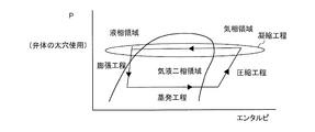
- FIG. 3 is a Mollier diagram of the refrigerant circuit of the refrigerator according to Embodiment 1 of the present invention in a normal flow state and a reverse flow state.
- FIG. 18 is an enlarged view of the condensation step of FIG. 17 in a normal flow state.
- FIG. 18 is an enlarged view of the condensing process of FIG. 17 in a reverse flow state.
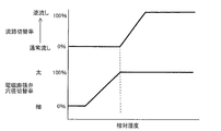
- FIG. 10 is a vertical cross-sectional view (a cross-sectional view taken along the line EE in FIG. 1) in which an injection hole is formed in the compartment partition shown in FIG. 9. It is a figure which shows the flow-path switching rate with respect to the relative humidity of the refrigerator which concerns on Embodiment 2 of this invention. It is a figure which shows the flow-path switching rate with respect to the relative humidity of the refrigerator which concerns on Embodiment 3 of this invention.
- FIG. 4 It is a block diagram of a refrigerant circuit of a refrigerator concerning Embodiment 4 of the present invention. It is a figure which shows the structure of the electromagnetic expansion valve used for the refrigerator which concerns on Embodiment 4 of this invention. It is a figure which shows the position of the valve body in the normal flow state of the electromagnetic expansion valve shown in FIG. It is a figure which shows the position of the valve body in the backflow state of the electromagnetic expansion valve shown in FIG. It is a 1st Mollier diagram in the normal flow state of the refrigerant circuit of the refrigerator concerning Embodiment 4 of the present invention. It is the 2nd Mollier diagram in the normal flow state of the refrigerant circuit of the refrigerator concerning Embodiment 4 of the present invention.
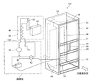
- Embodiment 1. 1 is a schematic front view of a refrigerator 100 according to Embodiment 1 of the present invention.
- FIG. 2 is a sectional view taken along the line AA of FIG.
- the configuration of the refrigerator 100 according to the first embodiment will be described.
- terms indicating directions are appropriately used, such as “upper”, “lower”, “right”, “left”, “front”, “rear”, etc. These terms are for the purpose of description and do not limit the present invention.
- “top”, “bottom”, “right”, “left”, “front”, “rear”, etc. are used when the refrigerator 100 is viewed from the front.
- the refrigerator 100 includes a plurality of storage chambers, and specifically, a refrigerating chamber 1, an ice making chamber 2, and a small freezing chamber 3.
- a freezer compartment 4 and a vegetable compartment 5 are provided.
- the refrigerating compartment 1 is provided at the top of the refrigerator 100, and the front opening is closed by two double doors that can be opened and closed.
- the two doors that open in a double door are composed of a refrigerating compartment left door 6 and a refrigerating compartment right door 7. Between the refrigerating compartment left door 6 and the refrigerating compartment right door 7, outside air enters between them.
- a partition plate 8 for preventing the above is provided.
- an ice making compartment 2 and a small freezing compartment 3 are arranged in parallel so that the storage compartment is pulled out to the user side when the ice making compartment door 92 and the small freezing compartment door 93 which are drawer type doors are pulled out. ..
- a vegetable compartment 5 is provided at the bottom of the refrigerator 100, and a freezing compartment 4 is provided above the vegetable compartment 5.
- the freezer compartment 4 is provided below the ice making compartment 2 and the small freezer compartment 3 arranged in parallel on the left and right sides, and above the vegetable compartment 5.
- the freezer compartment 4 and the vegetable compartment 5 are also configured such that the storage compartment is pulled out to the user side when the freezer compartment door 94 and the vegetable compartment door 95 which are drawer type doors are pulled out.
- each storage room is not limited to the first embodiment, and the arrangement of each storage room does not matter as long as it has a double door.
- the refrigerator 100 is equipped with an ambient temperature sensor 34 and an ambient humidity sensor 35.
- the ambient temperature sensor 34 detects the ambient temperature of the refrigerator 100.
- the ambient humidity sensor 35 detects the relative humidity around the refrigerator 100.
- the ambient temperature sensor 34 and the ambient humidity sensor 35 may be installed at any location as long as they can detect the ambient temperature and the relative humidity.
- the ambient temperature sensor 34 and the ambient humidity sensor 35 should be installed at positions that are not affected by the operation of the refrigerator 100, for example, the temperature effect of a condensation pipe (not shown) attached and fixed to the inside of the side surface of the refrigerator. desirable. Therefore, if the ambient temperature sensor 34 and the ambient humidity sensor 35 are installed at, for example, the upper hinge member (not shown) of the refrigerating compartment left door 6, they are not affected by the heat of the condensation pipe or the like.
- a control device 9 is provided on the back side of the refrigerator 100.
- the control device 9 includes, for example, dedicated hardware or a CPU (Central Processing Unit, central processing unit, processing device, arithmetic device, microprocessor, processor) that executes a program stored in a memory. There is.
- CPU Central Processing Unit, central processing unit, processing device, arithmetic device, microprocessor, processor
- a refrigerating compartment temperature sensor 38 for detecting the temperature of the refrigerating compartment 1 is installed on the surface of the refrigerating compartment air passage part 15.
- the refrigerating compartment temperature sensor 38 may be installed at any position as long as the temperature inside the refrigerating compartment 1 can be roughly observed.
- the control device 9 sends or shuts off the cool air to the refrigerating compartment 1 based on the temperature in the refrigerating compartment 1 detected by the refrigerating compartment temperature sensor 38 by operating the baffle 40 of the refrigerating compartment damper device 19. .
- this refrigerating compartment temperature sensor 38 controls energization to a heater (not shown) installed in the refrigerating compartment 1 for temperature compensation, a heater (not shown) installed in the partition plate 8, and the like. Used to do.
- three pockets 14 are attached along the height direction inside the refrigerator compartment left door 6 and the refrigerator compartment right door 7, and the interior of the refrigerator compartment 1 is divided into a plurality of shelves 13. ..
- a chilled room 17 (about 0° C.) lower than the temperature of the refrigerating room 1 (about 3° C.) is provided under the lowest shelf 13 in the refrigerating room 1.
- a refrigerating compartment air passage component 15 is provided on the back side of the refrigerating compartment 1, and a blowout port 16 through which air is blown from the refrigerating compartment blowing air passage 24 is formed in each part partitioned by the shelves 13.
- a refrigerating compartment damper device 19 is arranged between the internal fan 23 and the refrigerating compartment blowing air passage 24.
- a space between the inner box 11 and the outer box 12 is filled with a urethane foamed heat insulating material 10.
- the refrigerating compartment left door 6 is provided with a setting operation section 20 (broken line portion) by which a user can operate temperature setting and mode setting of each room.
- the refrigerating compartment 1 can be set to a temperature of weak (about 6° C.) to medium (about 3° C.) to strong (about 0° C.), and the freezer compartment 4 can be set.
- the temperature can be set from weak (about -16°C) to medium (about -18°C) to strong (about -20°C).
- the temperature of other rooms can be similarly set by the user operating the setting operation unit 20.
- the user can operate the setting operation unit 20 to set the energy saving priority mode and the dew condensation countermeasure mode, which will be described later.
- the setting operation section 20 is operated in the hole (not shown) on the right side of the refrigerating compartment left door 6.
- the panel 50 is inserted. Since a capacitance sensor is used in the setting operation unit 20, touching the surface of the setting operation unit 20 with a finger enables operation of temperature setting and mode setting.
- An automatic ice maker (not shown) is installed on the ceiling of the ice making room 2, and water can be supplied from a water supply tank (not shown) installed in the refrigerating room 1 to make ice.
- the small freezer compartment 3 is designed so that cool air is blown out from a fan grill 22 installed on the back side of the refrigerator 100 to be cooled. Since both the ice making chamber 2 and the small freezing chamber 3 are drawer type doors, a case (not shown) for storing ice and a case 25 for storing food are provided.
- freezer compartment 4 cool air is blown out from the fan grill 22 installed on the back side of the refrigerator 100, and the inside of the refrigerator is cooled to about ⁇ 18° C. at a medium temperature setting on a time average.
- the freezer compartment 4 is also a drawer type door, and is provided with an upper case 27 and a lower case 28. Further, a freezer compartment temperature sensor 39 for detecting the temperature of the freezer compartment 4 is attached to the fan grill 22.
- FIG. 3 is a diagram showing a time transition such as operation of the compressor 36 of the refrigerator 100 according to the first embodiment of the present invention.
- FIG. 3 shows the temperature of the freezer compartment temperature sensor 39, the temperature of the refrigerating compartment temperature sensor 38, and the operation of the compressor 36 on the vertical axis with respect to time on the horizontal axis.
- the operation of the compressor 36 is controlled based on the temperature of the freezer compartment temperature sensor 39.
- the compressor 36 stops (OFF point), and when the freezer compartment temperature sensor 39 rises to the second predetermined value, the compressor 36 is stopped.
- the compressor 36 is driven by the differential control in which the operation of the compressor 36 starts (ON point).
- the average temperature of the freezer compartment 4 is set to about -18°C, so the OFF point is set lower than -18°C and the ON point is set higher than -18°C.
- the control device 9 instructs opening and closing of the baffle 40 of the refrigerating compartment damper device 19 at the opening point and closing at the closing point.
- the temperature setting of the refrigerating compartment 1 is the medium setting, the average temperature of the refrigerating compartment 1 is set. Since the temperature is about 3°C, the open point is set higher than 3°C and the close point is set lower than 3°C.
- the vegetable compartment 5 is cooled from the outlet on the back side of the refrigerator 100, and is cooled to about 6° C. when the temperature setting is medium. Further, the vegetable compartment 5 is also a drawer type door, and is provided with an upper case 32 and a lower case 33.
- the inside of the refrigerator 100 is partitioned by room partitioning sections 21, 26, 31 along the height direction.
- the partition parts 21, 26, 31 are made of resin plate-shaped molded products at the top and bottom, and are filled with a heat insulating material made of urethane foam or a molded product such as Styrofoam, and fixed with screws at the top and bottom.
- a partition plate (not shown) made of a sheet metal is provided on the front side surface of each of the partition parts 21, 26, 31 so as to be magnetically attached to the gasket 67 with a magnet attached to the door. ing.
- FIG. 4 is a first connection diagram of the refrigerant pipes inside the refrigerator 100 according to the first embodiment of the present invention.
- FIG. 5 is a second connection diagram of the refrigerant pipes inside refrigerator 100 according to Embodiment 1 of the present invention.
- the components of the refrigerant circuit 102 of the refrigerator 100 are the compressor 36, the flow path switching device 42, the fin-tube type machine chamber condenser 43, and the left side surface.
- the flow path switching device 42 is, for example, a four-way valve, but is not limited thereto, and may be configured by combining a two-way valve and a three-way valve, for example.
- the compressor 36, the flow path switching device 42, the machine room condenser 43, and the dryer 51 are installed in the machine room 37 provided in the lower portion on the back side of the refrigerator 100.
- the ceiling surface condensing pipe 45 extends from the left side surface condensing pipe 44 on the left side surface to the ceiling surface, but may be connected from the right side surface condensing pipe 54 on the right side surface.
- the left side condensing pipe 44, the ceiling condensing pipe 45, the back side condensing pipe 46, and the right side condensing pipe 54 are fixed to the inner surface of the outer box 12 with aluminum tape, although not shown.
- the refrigerant circuit 102 is configured by sequentially connecting a compressor 36, a flow path switching device 42, a condensation system piping, a flow path switching device 42, a dryer 51, a capillary tube 48, a cooler 30, and a muffler 52.
- the condensing system piping is the machine room condenser 43, the left side condensing piping 44, the ceiling condensing piping 45, the back condensing piping 46, the right side condensing piping 54, and the dew condensation prevention piping 47.
- the refrigerator 100 is provided with a machine room cooling fan (not shown) that cools the machine room condenser 43 and the compressor 36, and an in-compartment fan 23 (see FIG. 2) that circulates cool air into the room. ing. Further, if it is on the downstream side of the flow path switching device 42 after passing through the condensation system pipe, two capillary tubes 48 are installed (in that case, a three-way valve is installed on the upstream side of the capillary tube 48), and the cooler 30 Multiple units may be installed.
- the machine room condenser 43, the ceiling surface condensation pipe 45, and the rear surface condensation pipe 46 may be provided if the condensation capacity can be gained only by the left side condensation pipe 44 and the right side condensation pipe 54. ..
- the right front side is the front side of the refrigerator 100, and the dew condensation prevention pipe 47 is arranged in the cabinet flange portion 55 and the compartment partitions 21, 26, 31. Further, the dew condensation prevention pipe 47 is connected to the right side condensing pipe 54 at the lower right side, is arranged from the lower side of the refrigerator 100 to the compartment partitions 21, 26, 31 and the like, and surrounds the periphery of the refrigerator compartment 1. .. After that, the dew condensation prevention pipe 47 returns to the lower side of the refrigerator 100 along the cabinet flange portion 55 as it is, and is connected to the flow path switching device 42 arranged in the machine room 37 through the lower left side surface.
- the left and right sides of the dew condensation prevention pipe 47 may be connected in reverse as shown in FIG.
- the dew condensation prevention pipe 47 is connected to the flow path switching device 42 arranged in the machine room 37 on the lower right side, and is arranged from the lower side of the refrigerator 100 to the room partition parts 21, 26, 31 and the like. , Around the refrigerator compartment 1. After that, the dew condensation preventing pipe 47 returns to the lower side of the refrigerator 100 along the cabinet flange portion 55 as it is, and passes through the lower left side face to be connected to the left side face condensing pipe 44.
- the turn of the dew condensation prevention pipe 47 arranged in the inter-room partition 21 that partitions the refrigerating compartment 1 and the ice-making compartment 2 is on the lower side. It is arranged so as to extend one turn in the direction.
- the ice making chamber 2 and the small freezing chamber 3 and the freezing chamber 4 may be arranged so as to extend upward from the turns arranged in the inter-room partition 26.
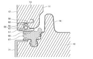
- FIG. 6 is a vertical cross-sectional view (a cross-sectional view taken along the line BB in FIG. 1) of the cabinet flange portion 55 on the upper side of the refrigerating compartment 1 of the refrigerator 100 according to Embodiment 1 of the present invention.
- FIG. 7 is a horizontal cross-sectional view (a cross-sectional view taken along the line CC of FIG. 1) of cabinet flange portions 55 on the left and right vertical sides of freezer compartment 4 of refrigerator 100 according to Embodiment 1 of the present invention.
- the cabinet flange portions 55 on the upper side and the left and right vertical sides of the refrigerator 100 are installed as shown in FIGS. 6 and 7.
- An inner box flange 57 having a recess 59 is inserted into an inner box grip-shaped portion 58 in which the outer box 12 made of sheet metal is bent, and a dew condensation prevention pipe 47 is installed in the recess 59.
- a sealing material 60 or the like is installed in the recess 59, and the dew condensation preventing pipe 47 installed thereon is provided so as to be in close contact with the outer box 12.
- the gasket 67 is provided with a magnet 68, and the magnetic force of the magnet 68 causes the gasket 67 to come into close contact with the outer casing 12 made of sheet metal.
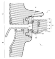
- FIG. 8 is a vertical cross-sectional view around the room partition 26 between the ice making room 2 and the small freezing room 3 and the freezing room 4 of the refrigerator 100 according to the first embodiment of the present invention (the DD cross section arrow in FIG. 1).
- FIG. 9 is a vertical cross-sectional view (a cross-sectional view taken along the line EE in FIG. 1) around the partition 31 between the freezer compartment 4 and the vegetable compartment 5 of the refrigerator 100 according to Embodiment 1 of the present invention.
- FIG. 10 is a vertical sectional view (a sectional view taken along the line DD in FIG. 1) in which butyl rubber 66 is provided on the back surface of the surface partition plate 61 shown in FIG. Strictly speaking
- FIG. 8 is a vertical cross-sectional view around the room partition 26 between the small freezer compartment 3 and the freezer compartment 4.
- the parts configuration of the partition parts 21, 26, 31 of each room is basically the same. Further, in the inter-room partition 26 shown in FIG. 8, the surface partition plate 61 made of sheet metal is screwed and fixed to the resin partition main body 64 in which the upper surface 62 and the lower surface 63 are made of a resin plate.
- the surface partition plate 61 has its strength increased by the upper and lower ends being bent inward.
- the surface partition plate 61 provided between the ice making chamber 2 and the small freezing chamber 3 has its left and right ends bent inward.
- the partition main body 64 has its upper and lower ends extending to the outside of the refrigerator and wraps with the bent portions of the upper and lower ends of the surface partition plate 61, and a space is formed between the surface partition plate 61 and the partition body 64. Has been done. In the space, the dew condensation prevention pipe 47 is pressed so as to come into close contact with the inner surface of the surface partition plate 61. In the compartment partitioning portion 26, the dew-prevention prevention pipe 47 is pressed to the outside of the refrigerator from the back side by a heat insulating material 91 such as expanded polystyrene as shown in FIG. Further, in the inter-room partition section 31, as shown in FIG. 9, the dew condensation prevention pipe 47 is pressed to the outside of the storage by sticking a pressing sealing material 65 or the like to the partition body 64 side.
- a heat insulating material 91 such as expanded polystyrene
- the dew condensation prevention pipe 47 is pressed to the outside of the compartment with respect to the compartments 26 and 31, but the difference between the heat insulating material 91 and the pressing sealing material 65 is due to the component configuration of the refrigerator 100. is there. Therefore, there is no problem even if the pressing sealing material 65 is applied to the room partition 26 and the heat insulating material 91 is applied to the room partition 31.
- the pressing of the dew condensation prevention pipe 47 from the back side may not make good contact with the back side of the surface partition plate 61. In such a case, the heat of the dew condensation prevention pipe 47 is not transferred well. Therefore, as shown in FIG.
- butyl rubber 66 or the like is attached to the back surface of the surface partition plate 61 to increase the contact area between the dew condensation prevention pipe 47 and the surface partition plate 61, and the heat of the dew condensation prevention pipe 47 is separated from the surface partition plate. You may make it convey to the board 61.
- a magnet 68 is provided in the gasket 67 so that the gasket 67 comes into close contact with the surface partition plate 61 by magnetic force.
- the door handle portion 69 is a drawer type door, it is often attached to the upper and lower caps 70 and 71 of the door, and is often formed of resin. In a double door type door, it is often attached to the lower cap of the door. Since FIG. 8 is a vertical cross section between the small freezer compartment 3 and the freezer compartment 4, the small freezer compartment door 93 and the freezer compartment door 94 are drawer-type doors, and the cap 70 on the upper side of the freezer compartment door 94 has a door. A handle portion 69 is provided. Further, since FIG. 9 is a vertical cross section between the freezer compartment 4 and the vegetable compartment 5, the freezer compartment door 94 and the vegetable compartment door 95 are drawer type doors, and the cap 70 on the upper side of the vegetable compartment door 95 has a door. A handle portion 69 is provided.
- FIG. 11 is an exploded perspective view showing the configuration of refrigerating room left door 6 of refrigerator 100 according to Embodiment 1 of the present invention.
- FIG. 12 is an exploded perspective view showing the configuration of refrigerating room right door 7 of refrigerator 100 according to Embodiment 1 of the present invention.
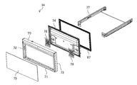
- FIG. 13 is an exploded perspective view showing the configuration of freezer compartment door 94 of refrigerator 100 according to Embodiment 1 of the present invention.
- the double door and the drawer door of the refrigerator 100 will be described.
- all the doors from the ice making compartment 2 to the vegetable compartment 5 are drawer type doors, but since the components are almost the same, the structure of the freezing compartment door 94 will be described here.
- the refrigerating compartment left door 6 and the refrigerating compartment right door 7 are composed of resin caps 70, 71, 72 and 73 on the upper, lower, left and right sides, the inner surface of the door is composed of a resin inner plate 74, and the door surface is made of glass. It is composed of a door surface panel 75.
- the inside of the refrigerating compartment left door 6 and the refrigerating compartment right door 7 is filled with urethane foam insulation 10.
- a partition plate 8 for closing the space between the refrigerating compartment left door 6 and the refrigerating compartment right door 7 is hinge-fixed to the side surface of the inner plate 74 on the center side so as to rotate when the door is opened and closed.
- the refrigerating room left door 6 is provided with a setting operation section 20 that allows the user to operate the temperature setting of each storage room and the mode setting.
- the partition plate 8 and the setting operation unit 20 may be provided on the refrigerating compartment right door 7.
- the cap 71 on the lower side of the refrigerating compartment left door 6 and the lower side of the refrigerating compartment right door 7 are provided with concave portions 71a, respectively, which serve as door handle portions.
- the door surface panel 75 may be a sheet metal panel, in which case the left and right caps 72, 73 may be omitted.
- the freezer compartment door 94 has a structure similar to that of the double-door type door with respect to the upper, lower, left, right, and front surfaces, but a holding member 78 for mounting a frame 77 on which the upper case 27 and the lower case 28 are mounted is provided inside the inner plate 74. And the frame 77 is fixed by screws. It should be noted that the door handle portion 69 may be provided either above or below the freezer compartment door 94, but in the first embodiment, it is provided on the upper cap 70.
- the double doors and drawer doors of the refrigerator 100 according to the first embodiment are configured as described above.
- heat from the dew condensation prevention pipe 47 provided in each of the compartment partitions 21, 26, 31 is conducted through the gasket 67 and the caps 70, 71. Can be warmed by.
- the heat from the inner plate 74 facing the inside of the refrigerator is conducted to be cooled. Therefore, the temperature of the door handle 69 is determined by a complicated thermal effect.
- FIG. 14 is a longitudinal section (a sectional view taken along the line DD in FIG. 1) showing a state where the vacuum heat insulating material 76 is provided on the freezer compartment door 94 shown in FIG. Although the urethane foam insulation 10 is filled inside the freezer compartment door 94, a vacuum insulation 76 may be provided between the door handle 69 and the inner plate 74 as shown in FIG. .. Since the thermal conductivity of the vacuum heat insulating material 76 is about 1/10 of the heat conductivity of the urethane foam heat insulating material 10, the amount of heat entering the inner plate 74 from the door handle 69 is reduced, and the temperature of the door handle 69 is reduced. It is effective to raise.
- FIG. 15 is a first block diagram of refrigerant circuit 102 of refrigerator 100 according to Embodiment 1 of the present invention.
- FIG. 15 shows the refrigerant circuit 102 in a normal flow state.
- the flow of the refrigerant in the normal flow state in the refrigerant circuit 102 is as shown by an arrow.
- the refrigerant discharged from the compressor 36 first enters the flow path switching device 42 and reaches the condensation system piping.
- the condensing system piping the machine room condenser 43, the left side condensing piping 44, the ceiling condensing piping 45, the back condensing piping 46, the right side condensing piping 54, and the dew prevention piping 47 flow in this order, and the flow path switching device 42.
- the left side condensing pipe 44, the ceiling condensing pipe 45, the rear condensing pipe 46, and the right side condensing pipe 54 are collectively referred to as a surface condensing pipe.
- FIG. 16 is a second block diagram of refrigerant circuit 102 of refrigerator 100 according to Embodiment 1 of the present invention.
- FIG. 15 shows the refrigerant circuit 102 in the reverse flow state. The flow of the refrigerant in the reverse flow state in the refrigerant circuit 102 is as shown by an arrow.
- the refrigerant discharged from the compressor 36 first enters the flow path switching device 42 and reaches the condensation system piping.
- the dew condensation prevention piping 47, the right side condensing piping 54, the back side condensing piping 46, the ceiling condensing piping 45, the left side condensing piping 44, and the machine room condenser 43 flow in this order, and the flow path switching device 42.
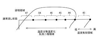
- FIG. 17 is a Mollier diagram of the refrigerant circuit 102 of the refrigerator 100 according to Embodiment 1 of the present invention in a normal flow state and a reverse flow state.
- FIG. 18 is an enlarged view of the condensing process of FIG. 17 in the normal flow state.
- FIG. 19 is an enlarged view of the condensation process of FIG. 17 in the reverse flow state.
- the state of the refrigerant in the dew condensation preventing pipe 47 is in the latter half of the condensation step, so that it is in a gas-liquid two-phase state to a liquid phase state.
- the reverse flow state the process is subsequent to the compression process by the compressor 36. Therefore, the inlet of the dew condensation preventing pipe 47 is in a gas phase state, and the outlet is in a gas-liquid two-phase state.
- the temperature of the refrigerant is higher toward the right side in the vapor phase region and isotherm changes in the gas-liquid two-phase region. Is higher than in the normal sink condition. Therefore, in the reverse flow state, it is possible to raise the temperature in the cabinet flange portion 55 and the door handle portion 69 as compared with the normal flow state.
- the point of the first embodiment is to use the sensible heat change on the vapor phase side for the temperature of the dew condensation prevention pipe 47. That is, the sensible heat change on the gas phase side can be used by controlling the flow path switching device 42 so that the inlet of the dew condensation preventing pipe 47 can be connected next to the compressor 36. Therefore, by connecting the pipes as in the first embodiment, it is possible to allow the high-temperature refrigerant to flow into the dew condensation prevention pipe 47, thereby improving the dew condensation resistance.
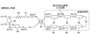
- FIG. 20 is a diagram showing actual machine temperature data of each part of the refrigerant circuit 102 in the normal flow state of the refrigerator 100 according to the first embodiment of the present invention.
- 21 is a figure which shows the actual machine temperature data of each part of the refrigerant circuit 102 in the backflow state of the refrigerator 100 which concerns on Embodiment 1 of this invention.
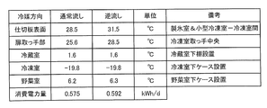
- FIG. 22 is the figure which compared the temperature of each part of the refrigerator 100 which concerns on Embodiment 1 of this invention in the normal flow state and the reverse flow state.
- the data shown in FIGS. 20 to 22 are actual measurement data when the flow path switching device 42 is attached to a refrigerator having a rated internal volume of 500 L and the refrigerator has an ambient temperature of 30° C. and a relative humidity of 50%. It is measured by switching the flow of the refrigerant by the path switching device 42 and fixing it in the normal flow state and the reverse flow state, respectively.
- the temperature of each part shown in FIG. 22 is a measurement of the pipe surface temperature of the refrigerator 100, and the inlet temperature of the dew condensation preventing pipe 47 in the reverse flow state is 32.3° C. to 35.2 as compared with the normal flow state. It can be seen that the temperature rises at about 3K. Since the freezing room temperature is the lowest in the room of the refrigerator 100, when the temperature around the freezing room is confirmed, the partition plate surface temperature and the freezing room of the room partitioning part 26 that separates the ice making room 2 and the small freezing room 3 from the freezing room 4 The surface temperature of the handle is also higher in the backflow state.
- the power consumption in the reverse flow state is about 3% higher than that in the normal flow state, but this causes the temperature of the dew condensation prevention pipe 47 to be high, and a large amount of heat enters from the upper and lower ends of the partition surface sheet metal. It is because it has become.
- FIG. 23 is a diagram showing the temperature of the door handle 69 with respect to the relative humidity of the refrigerator 100 according to Embodiment 1 of the present invention.
- the horizontal axis in FIG. 23 represents relative humidity and the vertical axis represents temperature.
- the solid line curve shows the dew point temperature when the ambient temperature of the refrigerator is 30°C.
- the temperature of the door handle portion 69 in the normal flow state is indicated by the first broken line, and the temperature in the reverse flow state is indicated by the second broken line.
- the temperature of the door handle 69 is higher than the dew point temperature until the relative humidity is around 80%, but when the relative humidity is higher than that, the temperature of the door handle 69 is dew point.
- the temperature inside the refrigerator rises due to the user opening and closing the door, and the temperature of the door handle 69 rises accordingly. Therefore, when the relative humidity is around 80%, dew does not necessarily adhere, but the risk of dew increases.
- the temperature of the dew condensation prevention pipe 47 rises, so that the temperature of the door handle 69 also rises, and the temperature of the door handle 69 does not fall below the dew point temperature until the relative humidity is around 90%.
- the control device 9 changes the time ratio between the normal flow state and the reverse flow state (this is referred to as a flow path switching rate) according to the relative humidity detected by the ambient humidity sensor 35.
- the flow path switching device 42 is switched to.
- FIG. 24 is a 1st figure which shows the flow-path switching rate with respect to the relative humidity of the refrigerator 100 which concerns on Embodiment 1 of this invention.
- FIG. 25 is a 2nd figure which shows the flow-path switching rate with respect to relative humidity of the refrigerator 100 which concerns on Embodiment 1 of this invention.
- the normal flow state is the flow path switching rate of 0%
- the reverse flow state is the flow path switching rate of 100%
- FIG. 24 shows the relative humidity on the horizontal axis and the flow path switching rate on the vertical axis.
- the control device 9 when detecting the relative humidity of 80%, the control device 9 sets 7 minutes of the 10-minute operation to the normal flow state and the remaining 3 minutes to the reverse flow state.
- the flow path switching rate at this time is 30%.
- the dew point temperature is lower than the temperature of the door handle 69 up to a relative humidity of 75%, so that the refrigerator is set in a normal sink state (flow path switching rate is 0%).
- the flow path switching rate is increased from the point where the relative humidity of the surroundings is higher than 75% and the dew point temperature exceeds the temperature of the door handle 69, and the flow path switching rate of 100% is detected when the relative humidity of 90% is detected.
- the flow path switching device 42 is controlled so as to always be in a reverse flow state.
- the flow path switching rate may be set stepwise so that the temperature of the handle 69 is always higher than the dew point temperature. At this time, such setting of the flow path switching rate is set separately for each ambient temperature stage.
- the ambient temperature stage is a stepwise capture of the ambient temperature of the refrigerator 100, such as ambient temperature of -10°C, 10°C-20°C, 20°C-30°C, 30°C-. Then, at each ambient temperature stage, the setting of the flow path switching rate with respect to the relative humidity as shown in FIGS. 24 and 25 is programmed in the control device 9. By doing so, it is possible to automatically change the flow path switching rate according to the ambient temperature and the relative humidity, and it is possible to provide the refrigerator 100 in which dew condensation does not occur even at high temperature and high humidity.
- the temperature of the dew condensation prevention pipe 47 can be greatly increased by the above control, so that it is not necessary to attach an aluminum tape or the like, and the cost is reduced. You can also
- FIG. 26 is a vertical cross-sectional view (a cross-sectional view taken along the line EE in FIG. 1) in which the injection hole 98 is formed in the partition 31 between the chambers shown in FIG.
- the space surrounded by the surface partition plate 61 and the partition body 64 may be filled with the urethane foam heat insulating material 10. Then, as shown in FIG. 26, when foaming the inside of the partition body 64 with the urethane foam heat insulating material 10, the heat insulating material 10 is wrapped around the space surrounded by the surface partition plate 61 and the partition body 64. An injection hole 98 is formed on the body 64 side.
- an air vent hole 97 is formed in the front part of the lower surface of the partition body 64 (the lower surface of this space) so that air is not accumulated during foaming, and the surface is covered with the sealing material 60 after foaming.
- the refrigerator 100 includes the compressor 36, the flow path switching device 42, the machine room condenser 43, the surface condensation pipe, the dew condensation prevention pipe 47, the decompression device, and the cooler 30.
- the refrigerant circuit 102 in which the refrigerant circulates, the ambient humidity sensor 35 that detects the relative humidity of the surroundings, and the control device 9 that controls the flow path switching device 42 are provided, and the control device 9 detects the ambient humidity sensor 35.
- the relative humidity is smaller than the preset reference value
- the normal flow state in which the refrigerant flows in the order of the compressor 36, the flow path switching device 42, the machine room condenser 43, the surface condensation pipe, and the dew condensation prevention pipe 47 is set.
- the compressor 36, the flow path switching device 42, the dew condensation prevention pipe 47, the surface condensation pipe, the machine room condensation The flow path switching device 42 is switched so that the refrigerant flows backward in the order of the container 43.
- the flow path switching device 42 when the relative humidity detected by the ambient humidity sensor 35 is equal to or higher than the reference value, the flow path switching device 42 is switched to be in the reverse flow state. That is, the sensible heat change on the gas phase side can be used by controlling the flow path switching device 42 so that the inlet of the dew condensation preventing pipe 47 can be connected next to the compressor 36. Therefore, a high temperature refrigerant can be allowed to flow into the dew condensation prevention pipe 47, and the dew condensation resistance can be improved.
- Embodiment 2 the second embodiment of the present invention will be described. However, the description of the same parts as those of the first embodiment will be omitted, and the same or corresponding parts as those of the first embodiment will be designated by the same reference numerals.
- the parts configuration of the refrigerator 100 according to the second embodiment is the same as that of the first embodiment.
- the refrigerator 100 according to the second embodiment shifts the flow path switching rate according to the temperature setting of the freezer compartment 4 selected by the user.
- the temperature of the freezer compartment 4 is set to a high temperature (about ⁇ 20° C.), an intermediate temperature (about ⁇ 18° C.), by the setting operation unit 20 provided on the refrigerating compartment left door 6.
- the user can set a low temperature (about -16°C).
- the flow path switching rate is shifted in the form of a broken line when the high temperature of the freezer compartment 4 is set, a solid line when the medium temperature is set, and a one-dot chain line when the weak temperature is set, and is low if the set temperature of the freezer compartment 4 is low.
- the flow path switching rate may be shifted according to the set temperature not only in the freezing room 4 but also in other storage rooms.
- the storage room in which the temperature is set to be the lowest in the refrigerator 100 is the freezing room 4, and the shift amount of the flow path switching rate according to the setting temperature in the other storage room depends on the setting temperature of the freezing room 4. It is preferable to set the flow path switching rate smaller than the shift amount. Then, as the flow path switching rate according to the set temperature of the freezer compartment 4, the highest flow path switching rate may be selected as compared with the flow path switching rates set in other storage chambers.
- Embodiment 3 Hereinafter, the third embodiment of the present invention will be described. However, the description of the same parts as those of the first and second embodiments will be omitted, and the same or corresponding parts as those of the first and second embodiments will be designated by the same reference numerals. ..
- the refrigerator 100 is equipped with three modes including an automatic mode, an energy saving priority mode, and a dew condensation countermeasure mode, and these modes are the setting operation unit provided in the refrigerating room left door 6.
- these modes are the setting operation unit provided in the refrigerating room left door 6.
- the environment in which the refrigerator 100 is installed such as the ambient temperature and the relative humidity, is greatly affected by the heat insulation and airtightness of the house, the place where it is installed, the influence of air conditioners such as air conditioners, and the replacement of air by opening windows. It depends. Depending on the environment, even if the temperature is high outside the house, the temperature and humidity are not so high inside the house, or conversely, the temperature is high like the outside of the house.
- FIG. 28 is a figure which shows the flow-path switching rate with respect to the relative humidity of the refrigerator 100 which concerns on Embodiment 3 of this invention.
- the user can select the mode according to the installation environment of the refrigerator 100, and the flow path switching rate is shifted according to the mode as shown in FIG. 28.
- the solid line is the automatic mode, and the flow path switching rate is automatically set by the control device 9 according to the ambient temperature and the relative humidity of the refrigerator 100.
- the alternate long and short dash line is the energy saving priority mode, which is the mode in which the flow path switching rate is set lower than that in the automatic mode, and the increase in the power consumption is suppressed by increasing the time ratio in the normal running state.
- This energy saving priority mode is suitable for the environment in which the refrigerator 100 is installed, where the ambient temperature and the relative humidity are relatively low.
- the broken line is a dew condensation countermeasure mode, which is a mode in which the flow path switching rate is set higher than that in the automatic mode, and the dew condensation is suppressed.
- a second energy saving priority mode that is an energy saving priority mode fixed to a normal sink state and a second dew condensation countermeasure mode that is a dew condensation countermeasure mode fixed to a reverse flow state are mounted. Good.
- the temperature of the freezer compartment 4 may be increased by about 1K along with the setting of the dew condensation countermeasure mode. This is because the risk of dew condensation is the highest in the storage room of the refrigerator 100 around the freezing room 4 having the lowest temperature.
- FIG. 29 is a first diagram showing a time transition of the rotation speed of the compressor 36 and the like in the automatic mode of the refrigerator 100 according to the third embodiment of the present invention.
- FIG. 30 is a first diagram showing a time transition of the rotation speed of the compressor 36 and the like in the dew condensation countermeasure mode of the refrigerator 100 according to the third embodiment of the present invention.
- the difference between the ON point and the OFF point of the compressor 36 shown by the white arrow in FIG. 30, that is, the differential is made smaller than the differential in the automatic mode shown in FIG. 29. Good.
- ON/OFF of the compressor 36 is controlled by using a freezer compartment temperature sensor 39 installed on the inner side of the freezer compartment 4. Specifically, the control device 9 operates the compressor 36 when the freezer compartment temperature sensor 39 rises to the ON point, and stops the compressor 36 when it cools to the OFF point.
- the difference between the ON point and the OFF point of the compressor 36 in the dew condensation countermeasure mode is made smaller than that in the automatic mode so that the differential becomes smaller in the dew condensation countermeasure mode than in the automatic mode.
- the stop time of the compressor 36 can be shortened, and the time during which the refrigerant does not flow in the dew condensation preventing pipe 47 can be shortened. Therefore, the temperature decrease of the dew condensation prevention pipe 47 can be suppressed to a small level.
- the rotation speed of the compressor 36 during operation is the same as V1rps, the temperature of the dew condensation prevention pipe 47 during operation does not change between the dew condensation countermeasure mode and the automatic operation mode. Therefore, the average temperature of the door handle 69 and the like tends to rise.
- FIG. 31 is a second diagram showing a time transition of the rotation speed of the compressor 36 and the like in the automatic mode of the refrigerator 100 according to the third embodiment of the present invention.
- FIG. 32 is a second diagram showing a time transition of the rotation speed of the compressor 36 and the like in the dew condensation countermeasure mode of the refrigerator 100 according to the third embodiment of the present invention.
- the baffle 40 of the refrigerating compartment damper device 19 is opened and the internal fan 23 is operated while the compressor 36 is stopped to operate the refrigerating compartment. 1 may be cooled.
- the return air of the refrigerating compartment 1 comes in, so that the temperature rise of the cooler 30 while the compressor 36 is stopped becomes faster.
- cold air having a relatively high temperature flows into the freezing compartment 4 to quickly raise the temperature of the freezing compartment temperature sensor 39, and the ON point of the compressor 36 quickly reaches the ON point. You will arrive.
- the stop time of the compressor 36 can be shortened, the time during which the refrigerant does not flow in the dew condensation prevention pipe 47 can be shortened, and the temperature decrease of the dew condensation prevention pipe 47 can be suppressed to a small level. Further, since the rotation speed of the compressor 36 during operation is the same as V1rps, the temperature of the dew condensation prevention pipe 47 during operation does not change between the dew condensation countermeasure mode and the automatic operation mode. Therefore, the average temperature of the door handle 69 and the like tends to rise.
- an expansion device 79 is provided between the dew condensation prevention pipe 47 and the right side condensing pipe 54 for the purpose of lowering the temperature of the dew condensation prevention pipe 47.
- FIG. 33 is a block diagram of the refrigerant circuit 103 of the refrigerator 100 according to Embodiment 4 of the present invention.
- 34 is a figure which shows the structure of the electromagnetic expansion valve 80 used for the refrigerator 100 which concerns on Embodiment 4 of this invention.
- FIG. 35 is a diagram showing the position of the valve body 84 in the normal flow state of the electromagnetic expansion valve 80 shown in FIG.
- FIG. 36 is a diagram showing the position of the valve element 84 in the reverse flow state of the electromagnetic expansion valve 80 shown in FIG. 34.
- An electromagnetic expansion valve 80 shown in FIG. 34 is used as the expansion device 79 used in the refrigerant circuit 103 shown in FIG.
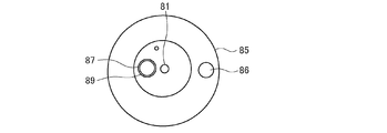
- the electromagnetic expansion valve 80 is a valve that is integrally fixed to the resin rotor portion 83 and the shaft 81 inside the coil portion 82 according to an instruction from the control device 9 and has a thin hole 88 and a thick hole 89.
- the body 84 is rotated to switch the flow path.
- a valve seat 85 is provided below the valve element 84, and an inlet pipe portion 86 and an outlet pipe portion 87 are connected to the valve seat 85.
- the electromagnetic expansion valve 80 rotates in the normal flow state by rotating the valve body 84 so that the small hole 88 having a small hole diameter is connected to the outlet pipe portion 87, depressurizes the refrigerant, and reduces the refrigerant flow rate. The refrigerant temperature before entering the anti-sticking pipe 47 is lowered.
- the valve body 84 rotates so that the thick hole 89 having a large hole diameter is connected to the outlet pipe portion 87.
- the electromagnetic expansion valve 80 operates together with the flow path switching of the flow path switching device 42, and in the normal flow state, the flow path is throttled by the electromagnetic expansion valve 80 on the upstream side of the dew condensation prevention pipe 47. As a result, the temperature of the dew condensation prevention pipe 47 decreases.
- FIG. 37 is a first Mollier diagram in the normal flow state of the refrigerant circuit 102 of the refrigerator 100 according to Embodiment 4 of the present invention.
- FIG. 38 is a second Mollier diagram in the normal flow state of the refrigerant circuit 102 of the refrigerator 100 according to the fourth embodiment of the present invention.
- FIG. 39 is a Mollier diagram in the reverse flow state of the refrigerant circuit 102 of the refrigerator 100 according to Embodiment 4 of the present invention.
- FIG. 40 is an enlarged view of the condensation process of FIG. 37.
- 41 is an enlarged view of the condensation step of FIG. 38.
- 42 is an enlarged view of the condensing process of FIG. 39.
- the valve body 84 of the electromagnetic expansion valve 80 When the relative humidity detected by the ambient humidity sensor 35 is lower than a predetermined threshold value, the valve body 84 of the electromagnetic expansion valve 80 is moved at an hourly rate. Therefore, the Mollier diagram in the normal sinking state has two patterns, that is, when the thin hole 88 of the valve body 84 shown in FIGS. 37 and 40 is used and when the thick hole 89 of the valve body 84 shown in FIGS. 38 and 41 is used. Become. Further, the Mollier diagram in the reverse flow state is as shown in FIGS. 39 and 42 because the valve body 84 is fixed to the thick hole 89.
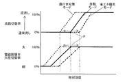
- FIG. 43 is a first diagram showing flow channel switching rates and hole diameter switching rates with respect to relative humidity of refrigerator 100 according to Embodiment 4 of the present invention.
- the flow path switching rate and the hole diameter switching rate of the electromagnetic expansion valve 80 with respect to the relative humidity will be described with reference to FIG.
- the time ratio between the time when the thick hole 89 of the valve body 84 of the electromagnetic expansion valve 80 is used and the time when the thin hole 88 is used is defined as the hole diameter switching ratio, and 0 when the thin hole 88 of the valve body 84 of the electromagnetic expansion valve 80 is used.
- the temperature of the door handle 69 is relatively high even when the flow path switching device 42 is kept in the normal flow state, and there is still room for temperature at a relative humidity of 50%. Therefore, when the relative humidity detected by the ambient humidity sensor 35 is lower than a predetermined value, the valve body 84 of the electromagnetic expansion valve 80 is switched between the thick hole 89 and the thin hole 88 at a time ratio in the normal flow state.
- the valve body 84 of the electromagnetic expansion valve 80 is fixed by the thick hole 89 so that the valve 84 does not expand thereafter, and the refrigerant flows backward.
- FIG. 44 is a second diagram showing the flow channel switching rate and the hole diameter switching rate with respect to the relative humidity of refrigerator 100 according to Embodiment 4 of the present invention. Further, the flow path switching rate and the hole diameter switching rate may be set by combining the energy saving priority mode and the dew condensation countermeasure mode described above. An example is shown in FIG. 44, and the point P of a predetermined relative humidity at which the normal flow state is fixed is shifted with the automatic mode as a solid line. In the energy saving priority mode (dashed line), the point P is raised, that is, shifted to the high humidity side (right side in FIG. 44), and in the dew condensation countermeasure mode (dashed line), the point P is lowered, that is, the low humidity side (see FIG. (On the left side of 44).
Landscapes
- Engineering & Computer Science (AREA)
- Chemical & Material Sciences (AREA)
- Combustion & Propulsion (AREA)
- Physics & Mathematics (AREA)
- Mechanical Engineering (AREA)
- Thermal Sciences (AREA)
- General Engineering & Computer Science (AREA)
- Devices That Are Associated With Refrigeration Equipment (AREA)
Abstract
La présente invention concerne un réfrigérateur qui comporte : un circuit de fluide frigorigène qui comporte un compresseur, un dispositif de commutation de passage d'écoulement, un condenseur de salle des machines, un tube de condensation de surface, un tube de prévention de condensation de rosée, un dispositif de mise en dépression et un refroidisseur, et à travers lequel circule un fluide frigorigène ; un capteur d'humidité ambiante pour détecter l'humidité relative ambiante ; et un dispositif de commande pour commander le dispositif de commutation de passage d'écoulement. Lorsque l'humidité relative détectée par le capteur d'humidité ambiante est inférieure à une valeur de référence prédéfinie, le dispositif de commande commute le dispositif de commutation de passage d'écoulement de telle sorte qu'un fluide frigorigène s'écoule dans un état d'écoulement normal dans lequel le fluide frigorigène s'écoule à travers le compresseur, le dispositif de commutation de passage d'écoulement, le condenseur de salle des machines, le tube de condensation de surface et le tube de prévention de condensation de rosée dans cet ordre ; et lorsque l'humidité relative détectée par le capteur d'humidité ambiante n'est pas inférieure à la valeur de référence, le dispositif de commande commute le dispositif de commutation de passage d'écoulement de telle sorte qu'un fluide frigorigène s'écoule dans un état d'écoulement inverse dans lequel le fluide frigorigène s'écoule à travers le compresseur, le dispositif de commutation de passage d'écoulement, le tube de prévention de condensation de rosée, le tube de condensation de surface et le condenseur de salle des machines dans l'ordre inverse.
Priority Applications (2)
| Application Number | Priority Date | Filing Date | Title |
|---|---|---|---|
| JP2020558837A JP6956900B2 (ja) | 2018-12-11 | 2018-12-11 | 冷蔵庫 |
| PCT/JP2018/045493 WO2020121404A1 (fr) | 2018-12-11 | 2018-12-11 | Réfrigérateur |
Applications Claiming Priority (1)
| Application Number | Priority Date | Filing Date | Title |
|---|---|---|---|
| PCT/JP2018/045493 WO2020121404A1 (fr) | 2018-12-11 | 2018-12-11 | Réfrigérateur |
Publications (1)
| Publication Number | Publication Date |
|---|---|
| WO2020121404A1 true WO2020121404A1 (fr) | 2020-06-18 |
Family
ID=71077205
Family Applications (1)
| Application Number | Title | Priority Date | Filing Date |
|---|---|---|---|
| PCT/JP2018/045493 Ceased WO2020121404A1 (fr) | 2018-12-11 | 2018-12-11 | Réfrigérateur |
Country Status (2)
| Country | Link |
|---|---|
| JP (1) | JP6956900B2 (fr) |
| WO (1) | WO2020121404A1 (fr) |
Cited By (1)
| Publication number | Priority date | Publication date | Assignee | Title |
|---|---|---|---|---|
| JP2022013046A (ja) * | 2020-07-03 | 2022-01-18 | 日立グローバルライフソリューションズ株式会社 | 冷蔵庫 |
Citations (5)
| Publication number | Priority date | Publication date | Assignee | Title |
|---|---|---|---|---|
| JP2000065461A (ja) * | 1998-08-20 | 2000-03-03 | Hitachi Ltd | 冷蔵庫及びかかる冷蔵庫における結露防止運転制御方法 |
| JP2009174767A (ja) * | 2008-01-23 | 2009-08-06 | Sharp Corp | 冷蔵庫 |
| JP2012017920A (ja) * | 2010-07-08 | 2012-01-26 | Toshiba Corp | 冷蔵庫 |
| JP2014047835A (ja) * | 2012-08-31 | 2014-03-17 | Hitachi Appliances Inc | 冷媒切替弁およびこれを備える機器 |
| JP2016205669A (ja) * | 2015-04-20 | 2016-12-08 | 日立アプライアンス株式会社 | 冷蔵庫 |
-
2018
- 2018-12-11 JP JP2020558837A patent/JP6956900B2/ja not_active Expired - Fee Related
- 2018-12-11 WO PCT/JP2018/045493 patent/WO2020121404A1/fr not_active Ceased
Patent Citations (5)
| Publication number | Priority date | Publication date | Assignee | Title |
|---|---|---|---|---|
| JP2000065461A (ja) * | 1998-08-20 | 2000-03-03 | Hitachi Ltd | 冷蔵庫及びかかる冷蔵庫における結露防止運転制御方法 |
| JP2009174767A (ja) * | 2008-01-23 | 2009-08-06 | Sharp Corp | 冷蔵庫 |
| JP2012017920A (ja) * | 2010-07-08 | 2012-01-26 | Toshiba Corp | 冷蔵庫 |
| JP2014047835A (ja) * | 2012-08-31 | 2014-03-17 | Hitachi Appliances Inc | 冷媒切替弁およびこれを備える機器 |
| JP2016205669A (ja) * | 2015-04-20 | 2016-12-08 | 日立アプライアンス株式会社 | 冷蔵庫 |
Cited By (2)
| Publication number | Priority date | Publication date | Assignee | Title |
|---|---|---|---|---|
| JP2022013046A (ja) * | 2020-07-03 | 2022-01-18 | 日立グローバルライフソリューションズ株式会社 | 冷蔵庫 |
| JP7312148B2 (ja) | 2020-07-03 | 2023-07-20 | 日立グローバルライフソリューションズ株式会社 | 冷蔵庫 |
Also Published As
| Publication number | Publication date |
|---|---|
| JPWO2020121404A1 (ja) | 2021-09-02 |
| JP6956900B2 (ja) | 2021-11-02 |
Similar Documents
| Publication | Publication Date | Title |
|---|---|---|
| JP5402779B2 (ja) | 冷蔵庫 | |
| US9644887B2 (en) | Heat exchanger assembly, refrigerator, and method of controlling a refrigerator | |
| JP4954484B2 (ja) | 冷却貯蔵庫 | |
| US11226145B2 (en) | Refrigerator and method for controlling a compressor based on temperature of storage compartment | |
| CN105814378B (zh) | 冰箱 | |
| JP2014020715A (ja) | 冷蔵庫 | |
| JP2012017920A (ja) | 冷蔵庫 | |
| CN113396307A (zh) | 具有直接冷却门内室的冷藏器具 | |
| CN103471319B (zh) | 冰箱的制冷系统及其控制方法、冰箱 | |
| CN102997558B (zh) | 冰箱 | |
| WO2020078280A1 (fr) | Appareil de réfrigérateur avec un compartiment convertible | |
| JP5506760B2 (ja) | 冷蔵庫 | |
| JP2021139591A (ja) | 冷蔵庫 | |
| JP2014234955A (ja) | 冷蔵庫 | |
| JP2012042143A (ja) | 冷蔵庫 | |
| CN104508408B (zh) | 冰箱 | |
| JP6956900B2 (ja) | 冷蔵庫 | |
| JP2016205669A (ja) | 冷蔵庫 | |
| JP6762149B2 (ja) | 冷蔵庫 | |
| JP2014059110A (ja) | 冷蔵庫および冷却機構 | |
| CN208332806U (zh) | 一种卧式无霜双温冷柜 | |
| JP5931329B2 (ja) | 冷蔵庫 | |
| JP2017040398A (ja) | 冷蔵庫 | |
| JP5501407B2 (ja) | 冷蔵庫 | |
| JP2007078205A (ja) | 冷蔵庫 |
Legal Events
| Date | Code | Title | Description |
|---|---|---|---|
| 121 | Ep: the epo has been informed by wipo that ep was designated in this application |
Ref document number: 18942814 Country of ref document: EP Kind code of ref document: A1 |
|
| ENP | Entry into the national phase |
Ref document number: 2020558837 Country of ref document: JP Kind code of ref document: A |
|
| NENP | Non-entry into the national phase |
Ref country code: DE |
|
| 122 | Ep: pct application non-entry in european phase |
Ref document number: 18942814 Country of ref document: EP Kind code of ref document: A1 |