WO2020121407A1 - Chaussure - Google Patents
Chaussure Download PDFInfo
- Publication number
- WO2020121407A1 WO2020121407A1 PCT/JP2018/045501 JP2018045501W WO2020121407A1 WO 2020121407 A1 WO2020121407 A1 WO 2020121407A1 JP 2018045501 W JP2018045501 W JP 2018045501W WO 2020121407 A1 WO2020121407 A1 WO 2020121407A1
- Authority
- WO
- WIPO (PCT)
- Prior art keywords
- twist
- shoe
- sole
- midsole
- foot
- Prior art date
- Legal status (The legal status is an assumption and is not a legal conclusion. Google has not performed a legal analysis and makes no representation as to the accuracy of the status listed.)
- Ceased
Links
Images





Classifications
-
- A—HUMAN NECESSITIES
- A43—FOOTWEAR
- A43B—CHARACTERISTIC FEATURES OF FOOTWEAR; PARTS OF FOOTWEAR
- A43B13/00—Soles; Sole-and-heel integral units
- A43B13/14—Soles; Sole-and-heel integral units characterised by the constructive form
- A43B13/141—Soles; Sole-and-heel integral units characterised by the constructive form with a part of the sole being flexible, e.g. permitting articulation or torsion
-
- A—HUMAN NECESSITIES
- A43—FOOTWEAR
- A43B—CHARACTERISTIC FEATURES OF FOOTWEAR; PARTS OF FOOTWEAR
- A43B13/00—Soles; Sole-and-heel integral units
- A43B13/14—Soles; Sole-and-heel integral units characterised by the constructive form
- A43B13/16—Pieced soles
-
- A—HUMAN NECESSITIES
- A43—FOOTWEAR
- A43B—CHARACTERISTIC FEATURES OF FOOTWEAR; PARTS OF FOOTWEAR
- A43B13/00—Soles; Sole-and-heel integral units
- A43B13/14—Soles; Sole-and-heel integral units characterised by the constructive form
- A43B13/18—Resilient soles
- A43B13/187—Resiliency achieved by the features of the material, e.g. foam, non liquid materials
- A43B13/188—Differential cushioning regions
-
- A—HUMAN NECESSITIES
- A43—FOOTWEAR
- A43B—CHARACTERISTIC FEATURES OF FOOTWEAR; PARTS OF FOOTWEAR
- A43B7/00—Footwear with health or hygienic arrangements
- A43B7/14—Footwear with health or hygienic arrangements with foot-supporting parts
- A43B7/1405—Footwear with health or hygienic arrangements with foot-supporting parts with pads or holes on one or more locations, or having an anatomical or curved form
- A43B7/1415—Footwear with health or hygienic arrangements with foot-supporting parts with pads or holes on one or more locations, or having an anatomical or curved form characterised by the location under the foot
- A43B7/142—Footwear with health or hygienic arrangements with foot-supporting parts with pads or holes on one or more locations, or having an anatomical or curved form characterised by the location under the foot situated under the medial arch, i.e. under the navicular or cuneiform bones
-
- A—HUMAN NECESSITIES
- A43—FOOTWEAR
- A43B—CHARACTERISTIC FEATURES OF FOOTWEAR; PARTS OF FOOTWEAR
- A43B7/00—Footwear with health or hygienic arrangements
- A43B7/14—Footwear with health or hygienic arrangements with foot-supporting parts
- A43B7/24—Insertions or other supports preventing the foot canting to one side , preventing supination or pronation
Definitions
- the present invention relates to shoes worn in sports and the like.
- Shoes worn in sports, etc. are required to follow the movements of the feet of the body when the wearer walks, runs, exercises, etc., and firmly supports the feet.
- Patent Document 1 discloses a cup-shaped stabilizer used for shoes.
- the cup-shaped stabilizer has a high hardness, and is divided into an inner shell side member and an outer shell side member from the bottom surface portion to the heel side wall portion, and by making the shape of the divided groove correspond to the load movement path, The impact when a load is applied is absorbed by the deformation of the bottom and midsole.
- Patent Document 2 discloses a shoe sole including an outer sole and a midsole.
- the midsole has a lower midsole and an upper midsole formed of a resin foam.
- the lower midsole is integrally formed with an outer winding upper portion that supports the outside of the foot from the side of the foot.
- the hardness of the outer part of the lower midsole including the outer winding upper part is the first hardness
- the hardness of the inner part of the lower midsole is the second hardness smaller than the first hardness.
- the hardness of the outer portion of the upper midsole is the third hardness, which is lower than the first hardness. Part or all of the outer winding upper part having high hardness projects above the upper midsole outside the upper midsole.
- the side of the foot extended to the side is grounded while the heel is raised while touching down. It may become a posture to support weight transfer to people.
- the foot is twisted inward from the ball of the toe toward the toe side.
- the cup-shaped stabilizer described in Patent Document 1 has an instep member having a high hardness, and thus serves as a resistance element against the inward twist on the rear side from the ball of the toe, and prevents the foot from twisting during the turning operation. It was not suitable for shoes that required followability.
- the hardness of the inner portion of the lower midsole is lower than that of the outer portion thereof, but the hardness of the inner portion of the lower midsole and the inner portion of the upper midsole arranged thereon are lower.
- the relationship with the hardness is unknown.
- the present invention has been made in view of these problems, and an object thereof is to provide a shoe having good followability to the twist of the foot in the turning operation.
- One aspect of the present invention is a shoe.
- the shoe is provided on the inner portion of the middle foot portion at the bottom, and is provided on the twist allowing portion that allows twisting inward on the heel side with respect to the toe side, and is arranged on the twist allowing portion.
- a bending restraint portion that restrains the heel side of the portion from bending upward.
- the followability to the twist of the foot in the turning operation becomes good.
- FIG. 1 is an exploded perspective view showing the outer appearance of the shoe according to the first embodiment.
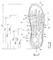
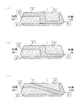
- FIG. 3 is a schematic view in which a skeleton model of a human foot is overlaid on a plan view of a shoe sole. It is an exploded perspective view of a shoe sole. It is a graph which shows an example of the elastic modulus of each part. It is a side view inside a shoe sole. It is a perspective view showing the appearance of the bottom side of the shoe sole. It is a schematic diagram for demonstrating bending at the time of the turning back operation
- FIG. 3 is a schematic view in which a skeleton model of a human foot is overlaid on a plan view of a shoe sole. It is an exploded perspective view of a shoe sole. It is a graph which shows an example of the elastic modulus of each part. It is a side view inside a shoe
- FIG. 8 is a schematic diagram for explaining the rigidity in the cross section of the shoe sole along the line BB shown in FIG. 7. It is a perspective view of a shoe sole cut in a cross section orthogonal to the front-back direction Y in the middle foot portion.
- 11(a) to 11(c) are schematic views for explaining the rigidity of the cross section of the shoe sole according to the modified example.
- 12(a) to 12(c) are schematic diagrams for explaining the rigidity in the cross section of the shoe sole according to another modification.
- FIG. 1 is an exploded perspective view showing the outer appearance of the shoe 100 according to the first embodiment.
- the shoe 100 has an upper 9 and a sole 1.
- the upper 9 is adhered or sewn to the peripheral portion of the shoe sole 1 to cover the upper side of the foot.
- the shoe sole 1 includes an outer sole 10 and a midsole 20.
- the midsole 20 is laminated on the outer sole 10, and an insole or the like (not shown) is laminated.
- Fig. 2 is a schematic diagram in which a skeleton model of the human body is overlaid on the plan view of the sole 1.
- the foot of the human body is mainly composed of a wedge bone Ba, a cuboid bone Bb, a scaphoid bone Bc, a talus Bd, a calcaneus Be, a metatarsal bone Bf, and a toe bone Bg.
- the joints of the foot include MP joint Ja, Lisfranc joint Jb, and Chopard joint Jc.
- the Chopard joint Jc includes a cuboid heel joint Jc1 formed by the cuboid bone Bb and the calcaneus Be, and a talon-joint joint Jc2 formed by the scaphoid bone Bc and the talus bone Bd.
- the center line N of the foot is represented by a straight line connecting the center N3 of the big toe ball and the midpoint N3 of the center N2 of the small toe ball and the center N4 of the heel.
- the front-rear direction Y is parallel to the center line N
- the width direction X is orthogonal to the center line N.
- a straight line along the width direction X (direction orthogonal to the center line N) that is supposed to pass through the heel side end of the MP joint Ja is defined as a line P.
- a straight line along the width direction X that is assumed to pass through the toe-side end of the wearer's Chopard joint Jc is defined as a line Q.
- the forefoot part is a region from the line P to the toe side
- the middle foot part is a region from the line P to the line Q
- the rear foot part is a region from the line Q to the heel side.
- the line P is located within the range of 40% to 75% from the rear end on the heel side with respect to the total length M of the shoe 100 in the direction of the center line N. More preferably, it is located within the range of 55% to 70% from the rear end.
- the line Q is located in the range of 20% to 45% from the rear end on the heel side with respect to the total length M of the shoe 100 in the direction of the center line N. More preferably, it is located within the range of 25% to 40% from the rear end.
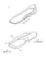
- FIG. 3 is an exploded perspective view of the shoe sole 1.
- the outer sole 10 has a bottom surface portion that is grounded on the road surface formed over the entire length in the front-rear direction Y of the foot, and has a toe protection portion 11 that is rolled up to protect the toes.
- the toe protector 11 extends to the inner side of the forefoot with the height gradually decreasing.
- An outer reinforcing member 12 formed as a separate body is disposed on the outer side portion of the outer sole 10, and is joined to the outer sole 10 by adhesion or the like.
- the outer reinforcing member 12 extends from the middle foot portion, that is, the middle portion of the front-rear direction Y toward the toe side and the heel side, and is formed in a wall shape that covers the outer side portion of the toe and the heel.
- the outer reinforcing member 12 may be integrally formed with the outer sole 10 and has the same material as the outer sole 10 as long as it has a function of suppressing lateral shake of the foot as described later. May also be different materials.
- the outer reinforcing member 12 corresponds to the lateral shake suppressing portion according to the present invention.
- the midsole 20 is arranged on the outer sole 10 and is formed from the toes to the heel.
- An inner reinforcing member 21 formed as a separate body is disposed inside the midsole 20, and is joined to the midsole 20 by adhesion or the like.
- the inner reinforcing member 21 extends from the middle foot part, that is, the middle part of the front-rear direction Y to the heel side, and is formed in a wall shape that covers the inner part, the rear part, and the outer part of the heel.
- the inner reinforcing member 21 may be formed integrally with the midsole 20 as long as it has a function of suppressing upward bending of the heel side from the rear part of the middle foot part to the heel as described later.
- the material may be the same as or different from that of the midsole 20.
- the inner reinforcing member 21 corresponds to the bending suppressing portion according to the present invention.
- the outer sole 10 is formed of, for example, rubber or resin, or a composite material such as rubber and resin.
- the midsole 20 is formed of, for example, a resin foam.
- a thermoplastic resin such as EVA (ethylene-vinyl acetate copolymer) or a thermosetting resin such as PU (polyurethane) is used, and may optionally contain any other component. It may also be formed of a foam of a rubber material such as butadiene rubber.
- the outer reinforcing member 12 and the inner reinforcing member 21 are formed of a non-foamed material or a foamed material of a thermoplastic resin such as TPU (thermoplastic polyurethane) or a thermosetting resin such as an epoxy resin.
- the hardness P2 of the midsole is lower than the hardness P1 of the outer sole 10, and the midsole 20 is easier to bend than the outer sole 10.
- the hardness P3 of the outer reinforcing member 12 and the hardness P4 of the inner reinforcing member 21 are higher than the hardness P1 of the outer sole 10, and the outer reinforcing member 12 and the inner reinforcing member 21 are more difficult to bend than the outer sole 10 and the midsole 20.
- the materials listed here are merely examples, and the materials used for each part are not limited to these.
- the hardness P4 of the inner reinforcing member 21 is higher than the hardness P3 of the outer reinforcing member 12, and the inner reinforcing member 21 is less likely to bend than the outer reinforcing member 12.
- the hardness P1 of the outer sole 10 may be set to HA70, the hardness P2 of the midsole 20 to HC58, the hardness P3 of the outer reinforcing member 12 to HA75, and the hardness P4 of the inner reinforcing member 21 to HA95.
- the elastic modulus can also be used as an index of bending difficulty.
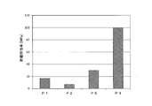
- FIG. 4 is a graph showing an example of the elastic modulus of each portion. In FIG.
- the storage elastic modulus (about 25° C., 10 Hz) of each portion measured by the viscoelasticity measuring device is shown.
- the outer sole 10 can be set to a storage elastic modulus of about 17 MPa, the midsole 20 to about 7 MPa, the outer reinforcing member 12 to about 30 MPa, and the inner reinforcing member 21 to about 100 MPa.
- the hardness P3 of the outer reinforcing member 12, the hardness P4 of the inner reinforcing member 21, and the respective storage elastic moduli may be substantially the same.
- the hardness and the storage elastic modulus described above are all examples, and can be set to different values as long as the relationship between the hardness and elastic modulus of each member is satisfied.
- FIG. 5 is a side view of the inside of the shoe sole 1.
- a portion of the midsole 20 corresponding to the middle foot portion on the inner side is a twist allowing portion 22.
- the twist allowing portion 22 has an inclined portion 22 a that extends upward from the rear side toward the front side and projects in front of the inner reinforcing member 21 in the front side portion.
- the inner reinforcing member 21 is arranged on the twist allowing portion 22.
- the inner reinforcing member 21 has a high hardness P4 and a high rigidity, it functions as a portion that suppresses the upward bending of the heel side in the inner portion.
- the twist allowable portion 22 has a low hardness P2 (which is the hardness of the midsole 20) and a low rigidity, the heel portion is allowed to bend upward on the heel side and twist inward on the heel side. Function as a part.
- the twisting allowance portion 22 may reduce rigidity by forming a groove or reducing the thickness.
- FIG. 6 is a perspective view showing the outer appearance of the bottom side of the shoe sole 1.
- the inside of the recess 13 is open, and the front edge 13a is parallel to the width direction X or is slightly inclined rearward from the inside to the outside.
- the rear edge 13b of the recess 13 is inclined forward from the inner side toward the outer side, and is then inclined backward from the middle part.
- the recess 13 is provided up to a midway portion (generally the center) of the shoe sole 1 in the width direction X, and extends from the outer end of the front edge 13a to the groove 13c.
- the thickness of the outer sole 10 is reduced, and the outer sole 10 functions as a portion that allows the heel side to bend upward and the heel side to twist inward.
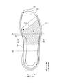
- FIG. 7 is a schematic view for explaining bending of the shoe sole 1 during the turning operation
- FIG. 8 is a schematic diagram showing a deformed state of the shoe sole 1 during the turning operation.
- Position A shown in FIG. 7 indicates the position of the big toe ball.
- a line L represents a line that is inclined from the rear of the position A of the toe ball in the inner portion to the front as it goes to the outer portion. During the turning operation, the front side of the line L is grounded and the rear side of the line L is twisted inward.
- the inclination angle of the line L is assumed to be, for example, about 45° with respect to the width direction X, but the inclination angle of the line L changes depending on individual differences in the turning operation.
- the line L does not have to be strictly behind the position A of the toe ball in the inner part, and may be located in front of the position A of the toe ball in the inner part, for example, as indicated by L1 in FIG. It may be.
- a hatched region R shown in FIG. 7 indicates a portion of the shoe sole 1 that allows the heel side to bend upward and the heel side to inwardly twist.
- the twist allowance portion 22 is formed in the middle foot portion of the inner side portion of the shoe sole 1.
- the twist allowable portion 22 is bent and deformed in the middle foot portion of the inner side portion of the shoe sole 1 so as to follow the inward twist on the rear side from the big toe ball, and the followability to the twist of the foot during the turning operation is good.
- the twist-allowing portion 22 is provided integrally with the midsole 20, it is not necessary to prepare or join another member to form the twist-allowing portion 22, and the manufacturability of the shoe 100 is improved. You can
- the twist allowing portion 22 has an inclined portion 22a that extends upward from the rear side toward the front side and projects in front of the inner reinforcing member 21 in the front side portion. Due to the deformation along the line L shown in FIG. 7, the deformation due to the twist is allowed even in the upper portion.
- Providing the inclined portion 22a has the effect of increasing the followability from the ball of the toe to the inward twist on the rear side in the middle foot of the inner side of the shoe sole 1.
- FIG. 9 is a schematic diagram for explaining the rigidity in the cross section of the shoe sole 1 along the line BB shown in FIG. 7.
- the twist allowance portion 22 on the inner side portion of the shoe sole 1 as described above, the followability to the turning operation is improved.
- An outer reinforcing member 12 is provided on the outer side portion of the shoe sole 1, and by setting the hardness P3 of the outer reinforcing member 12 to be high, lateral shake of the foot is suppressed.
- the shoe sole 1 to which the present invention is applied is not limited to the configuration including the outer sole 10 and the midsole 20.
- the outer sole 10 may be divided into a front foot portion and a rear foot portion.
- the twist-allowing portion 22 formed by the midsole 20 may be included in the midsole 20 or may be formed separately from the midsole 20. Further, even in the configuration of the shoe sole 1 in which the midsole 20 extending from the toe to the heel is not provided, if the portion corresponding to the twist allowing portion 22 is provided in the inner portion of the shoe sole 1, the cutback is performed. The followability to the operation becomes good.
- the outer reinforcing member 12 extends to the toe side from the middle foot portion, that is, the middle portion of the front-rear direction Y, and covers the outer side portion of the toe, thereby suppressing lateral shake of the toe portion of the foot. Further, the outer reinforcing member 12 extends from the middle foot portion to the heel side and covers the outer side portion of the heel, so that lateral shake at the heel side portion of the foot can be suppressed. The outer reinforcing member 12 does not have to extend to the toes and the heel side.
- FIG. 10 is a perspective view of the shoe sole 1 taken along a cross section orthogonal to the front-rear direction Y in the middle foot portion.
- FIG. 10 is a perspective view of the shoe sole 1 viewed from the outside. Looking at the cross section of the outer reinforcing member 12 shown in FIG. 10, a recessed portion 12a that is recessed outwardly in the middle of the vertical direction is formed at least from the middle foot portion to the rear foot portion. An upper edge 12b is formed on the upper side of the recess 12a, and a lower edge 12c is formed on the lower side.
- the upper edge portion 12b and the lower edge portion 12c have a thickness larger than the thickness of the bottom portion of the recess 12a in the width direction X, and the bending rigidity of the outer reinforcing member 12 against bending deformation such that the heel side is lifted. Be improved. Further, since the upper edge portion 12b is thicker in the width direction X than the bottom portion of the concave portion 12a, when the weight is applied to the outside of the foot, the weight is firmly supported and the stable turning operation is smoothly performed. Is possible.
- the inner reinforcing member 21 is disposed on the twist allowing portion 22 and keeps the heel side from the rear part of the middle foot portion highly rigid while suppressing upward bending deformation of the heel side in the twist allowing portion 22. ing.
- the inner reinforcing member 21 extends from the middle foot part, that is, the middle part of the front-rear direction Y to the heel side, and covers the inner part, the rear part, and the outer part of the heel, so that the heel is raised in the vertical direction. Supportability for rotation around the axis is improved.
- the inner reinforcing member 21 does not need to be provided with a portion that covers the inner portion, the rear portion, and the outer portion of the heel.
- the outer sole 10 has a recess 13 in the middle foot part, that is, in the middle part in the front-rear direction so as to be drilled from the bottom side, and the thickness of the outer sole 10 is thin in the recess 13.
- the recess 13 reduces the rigidity of the middle foot portion, so that the followability to the turning operation is improved.
- the recess 13 is opened on the inner side in the width direction X and is provided up to a midway portion in the width direction X, so that it is deformed in response to the deformation in the inner part in the torsional deformation during the turning operation, and the sole 1 In the outer side portion of B, there is an effect that bending deformation is suppressed.
- (Modification) 11(a) to 11(c) are schematic views for explaining the rigidity in the cross section of the shoe sole 1 according to the modified example.
- 11(a) to 11(c) schematically show a cross section taken along line BB shown in FIG. 7, where a low rigidity portion is D, a medium rigidity portion is E, and a high rigidity portion is high. Is represented by F.
- the shoe sole 1 will have the outer sole 10 and Not limited to the configuration of the midsole 20, the followability to the turning operation becomes good.
- the distribution of rigidity in the inner portion of the shoe sole 1 is the same as in the above-described first embodiment.
- a high-rigidity portion is provided on the lower portion
- a low-rigidity portion is provided on the lower portion.
- the effect of suppressing the lateral shake of the foot is reduced as compared with the first embodiment, but bending deformation is more likely to occur in the outer side portion of the shoe sole 1 as well, and the inward twist on the rear side from the ball of the big toe is likely to occur. It has the effect of increasing followability.
- the distribution of rigidity in the inner side portion and the outer side portion of the shoe sole 1 is the same as that in the above-described first embodiment, but the high rigidity portions in the inner side portion and the outer side portion are continuous. Has been formed.
- the high-rigidity portions in the inner portion and the outer portion are formed so as to be continuous as in the example shown in FIG. 11B, but from the upper portion of the inner portion to the outer portion.
- the area down to the bottom is also a highly rigid part.
- the strength is further increased by increasing the occupied area of the portion having higher rigidity than the example shown in FIG. 11B.
- 12(a) to 12(c) are schematic diagrams for explaining the rigidity in the cross section of the shoe sole 1 according to another modification.
- 12(a) to 12(c) schematically show a cross section taken along the line BB shown in FIG. 7, where a low-rigidity portion is D, a medium-rigidity portion is E, and high rigidity is shown. Is represented by F.
- the shoe sole 1 includes the outer sole 10 and Not limited to the configuration of the midsole 20, the followability to the turning operation becomes good.
- the distribution of rigidity in the inner side portion and the outer side portion of the shoe sole 1 is the same as that in the above-described first embodiment.
- the high-rigidity portion of the inner portion extends outward, extends to the lower portion in the middle portion, and is continuous with the high-rigidity portion of the outer portion at the lower portion. Since the rigidity distribution in the inner side portion and the outer side portion of the shoe sole 1 is the same as that of the above-described first embodiment, the followability to the turning motion is good and the lateral shake of the foot is suppressed. Moreover, the strength of the shoe sole 1 is increased by the continuous high-rigidity portion of the inner side portion and the high-rigidity portion of the outer side portion.
- the distribution of rigidity in the inner portion of the shoe sole 1 is the same as that in the above-described first embodiment, but in the outer portion of the shoe sole 1, a highly rigid portion is provided in the lower portion, A low-rigidity portion is provided on it.
- the high-rigidity portion extends from the inner side portion of the shoe sole 1 to the outer side, extends to the lower portion in the middle portion, and is continuous with the high-rigidity portion of the outer side portion in the lower portion.
- the high-rigidity portions in the inner portion and the outer portion are formed so as to be continuous, but from the upper portion of the inner portion to the outer portion. It extends so as to incline toward the lower part of the section and is continuous. In this example, it is expected that the followability to the turning operation is improved, the lateral shake of the foot is suppressed, and the strength of the sole 1 is improved.
- the shoe 100 has a twist allowing portion 22 and an inner reinforcing member 21 (bending suppressing portion).
- the twist allowable portion 22 is provided on the inner side of the middle foot portion of the shoe sole 1 as the bottom portion, and allows the heel side to be twisted inward with respect to the toe side.
- the inner reinforcing member 21 is disposed on the twist allowing portion 22 and suppresses the heel side of the inner portion from bending upward. As a result, the shoe 100 has good followability to the twist of the foot during the turning operation.
- the shoe 100 has an outer reinforcing member 12 (lateral shake suppressing portion) which is provided on the outer side portion of the shoe sole 1 and has a hardness higher than that of the twist allowing portion 22. Accordingly, the shoe 100 can suppress lateral shake of the foot while maintaining the followability to the twist of the foot.
- an outer reinforcing member 12 lateral shake suppressing portion
- the outer reinforcing member 12 is provided from the middle part in the front-rear direction to the outer part of the toe. As a result, the shoe 100 can suppress lateral shake of the toe part of the foot.
- the inner reinforcing member 21 is provided from the middle part in the front-rear direction to the heel part.
- the shoe 100 has good supportability for rotation about the vertical axis when the heel is raised.
- the twist allowing portion 22 has an inclined portion 22a extending upward from the rear side toward the front side in the front side portion.
- the inclined portion 22a projects in front of the inner reinforcing member 21.
- the shoe sole 1 has an outer sole 10 that is grounded on the road surface, and a midsole 20 that is arranged on the outer sole 10.
- the twist allowing portion 22 is formed on the inner side of the midsole 20.
- the shoe 100 is provided with the twist-allowing portion 22 integrally with the midsole 20, so that it is not necessary to prepare or join another member to form the twist-allowing portion 22, and thus the manufacturability of the shoe 100 is improved. Can be increased.
- a recess 13 is formed in the middle of the outer sole 10 in the front-rear direction so as to be drilled from the bottom side.
- the present invention relates to shoes.
Landscapes
- Health & Medical Sciences (AREA)
- Epidemiology (AREA)
- General Health & Medical Sciences (AREA)
- Public Health (AREA)
- Chemical & Material Sciences (AREA)
- Engineering & Computer Science (AREA)
- Materials Engineering (AREA)
- Footwear And Its Accessory, Manufacturing Method And Apparatuses (AREA)
Abstract
Priority Applications (5)
| Application Number | Priority Date | Filing Date | Title |
|---|---|---|---|
| PCT/JP2018/045501 WO2020121407A1 (fr) | 2018-12-11 | 2018-12-11 | Chaussure |
| JP2020558840A JP7261817B2 (ja) | 2018-12-11 | 2018-12-11 | 靴 |
| EP18942742.0A EP3797632A4 (fr) | 2018-12-11 | 2018-12-11 | Chaussure |
| US17/255,959 US12408727B2 (en) | 2018-12-11 | 2018-12-11 | Shoe |
| CN201880094526.7A CN112292054B (zh) | 2018-12-11 | 2018-12-11 | 鞋 |
Applications Claiming Priority (1)
| Application Number | Priority Date | Filing Date | Title |
|---|---|---|---|
| PCT/JP2018/045501 WO2020121407A1 (fr) | 2018-12-11 | 2018-12-11 | Chaussure |
Publications (1)
| Publication Number | Publication Date |
|---|---|
| WO2020121407A1 true WO2020121407A1 (fr) | 2020-06-18 |
Family
ID=71075980
Family Applications (1)
| Application Number | Title | Priority Date | Filing Date |
|---|---|---|---|
| PCT/JP2018/045501 Ceased WO2020121407A1 (fr) | 2018-12-11 | 2018-12-11 | Chaussure |
Country Status (5)
| Country | Link |
|---|---|
| US (1) | US12408727B2 (fr) |
| EP (1) | EP3797632A4 (fr) |
| JP (1) | JP7261817B2 (fr) |
| CN (1) | CN112292054B (fr) |
| WO (1) | WO2020121407A1 (fr) |
Cited By (2)
| Publication number | Priority date | Publication date | Assignee | Title |
|---|---|---|---|---|
| JP2022151189A (ja) * | 2021-03-26 | 2022-10-07 | 美津濃株式会社 | シューズ用ソール構造及びそれを備えたシューズ |
| WO2025074899A1 (fr) * | 2023-10-04 | 2025-04-10 | 株式会社アシックス | Chaussures |
Families Citing this family (5)
| Publication number | Priority date | Publication date | Assignee | Title |
|---|---|---|---|---|
| CN115175582A (zh) | 2020-01-10 | 2022-10-11 | 耐克创新有限合伙公司 | 具有多个硬度和/或弯曲促进结构的鞋底结构 |
| USD1010294S1 (en) * | 2020-07-14 | 2024-01-09 | Reebok International Limited | Shoe |
| US12302981B2 (en) * | 2022-03-03 | 2025-05-20 | Nike, Inc. | Article of footwear having a rand |
| US12419385B2 (en) * | 2022-12-28 | 2025-09-23 | Nike, Inc. | Article of footwear including an integrated stability member |
| USD1037631S1 (en) * | 2023-09-29 | 2024-08-06 | Nike, Inc. | Shoe |
Citations (6)
| Publication number | Priority date | Publication date | Assignee | Title |
|---|---|---|---|---|
| JPH0947305A (ja) | 1995-08-04 | 1997-02-18 | Mizuno Corp | カップ状スタビライザー |
| JP2005304653A (ja) * | 2004-04-20 | 2005-11-04 | Asics Corp | 靴のフレーム装置、金型装置および成型方法 |
| JP2006136715A (ja) * | 2003-10-17 | 2006-06-01 | Asics Corp | 強化構造を備えた靴底 |
| WO2013168256A1 (fr) | 2012-05-10 | 2013-11-14 | 株式会社アシックス | Semelle comprenant une semelle d'usure et une semelle intercalaire |
| US20160338446A1 (en) * | 2015-05-18 | 2016-11-24 | JV International S.r.l. | Shoe sole and a shoe comprising such sole |
| JP6396628B1 (ja) * | 2017-10-09 | 2018-09-26 | 株式会社アシックス | 強化装置を備えたシューソールの構造 |
Family Cites Families (18)
| Publication number | Priority date | Publication date | Assignee | Title |
|---|---|---|---|---|
| JP3258628B2 (ja) | 1998-09-08 | 2002-02-18 | 株式会社アシックス | 運動靴 |
| US6467197B1 (en) * | 1999-05-31 | 2002-10-22 | Asics Corp. | Shoe with arch reinforcement |
| US7533476B2 (en) * | 2001-02-21 | 2009-05-19 | Bivab, Llc | Foot guided shoe sole and footbed |
| US6578290B1 (en) * | 2001-10-17 | 2003-06-17 | Meynard Designs, Inc. | Shoe sole |
| EP1795083B1 (fr) * | 2002-04-10 | 2009-01-14 | Wolverine World Wide, Inc. | Semelle de chaussure |
| US8112909B2 (en) | 2003-10-17 | 2012-02-14 | Asics Corporation | Sole with reinforcement structure |
| WO2009106076A1 (fr) * | 2008-02-27 | 2009-09-03 | Ecco Sko A/S | Semelle de chaussure, destinée en particulier à une chaussure de course |
| US8186079B2 (en) * | 2009-05-06 | 2012-05-29 | Nike, Inc. | Article of footwear with sipes |
| DE102011051444A1 (de) * | 2011-06-29 | 2013-01-03 | Deeluxe Sportartikel Handels Gmbh | Sohle für einen Schuh, insbesondere Laufschuh |
| JP2015526251A (ja) * | 2012-08-31 | 2015-09-10 | スペンコ メディカル コーポレーション | バスケットボール・インソール |
| US20140325876A1 (en) * | 2013-05-02 | 2014-11-06 | Wolverine World Wide, Inc. | Sole assembly for article of footwear |
| US10226906B2 (en) * | 2014-04-14 | 2019-03-12 | Nike, Inc. | Method of manufacturing sole assembly formed of multiple preforms |
| DE102014107751A1 (de) * | 2014-06-03 | 2015-12-03 | Deeluxe Sportartikel Handels Gmbh | Schuh, insbesondere Laufschuh |
| JP6639078B2 (ja) * | 2014-09-17 | 2020-02-05 | 株式会社アシックス | O脚の人に適した靴および靴底 |
| US9615625B1 (en) * | 2015-09-17 | 2017-04-11 | Wolverine Outdoors, Inc. | Sole assembly for article of footwear |
| US10058145B2 (en) * | 2016-03-04 | 2018-08-28 | Nike, Inc. | Article of footwear and sole structure with a central sensory node element |
| US10772382B2 (en) * | 2018-06-04 | 2020-09-15 | Cole Haan Llc | Shoe having stiffening features |
| US11109642B2 (en) * | 2018-09-27 | 2021-09-07 | Reebok International Limited | Layered foam sole for an article of footwear |
-
2018
- 2018-12-11 JP JP2020558840A patent/JP7261817B2/ja active Active
- 2018-12-11 WO PCT/JP2018/045501 patent/WO2020121407A1/fr not_active Ceased
- 2018-12-11 CN CN201880094526.7A patent/CN112292054B/zh active Active
- 2018-12-11 EP EP18942742.0A patent/EP3797632A4/fr active Pending
- 2018-12-11 US US17/255,959 patent/US12408727B2/en active Active
Patent Citations (6)
| Publication number | Priority date | Publication date | Assignee | Title |
|---|---|---|---|---|
| JPH0947305A (ja) | 1995-08-04 | 1997-02-18 | Mizuno Corp | カップ状スタビライザー |
| JP2006136715A (ja) * | 2003-10-17 | 2006-06-01 | Asics Corp | 強化構造を備えた靴底 |
| JP2005304653A (ja) * | 2004-04-20 | 2005-11-04 | Asics Corp | 靴のフレーム装置、金型装置および成型方法 |
| WO2013168256A1 (fr) | 2012-05-10 | 2013-11-14 | 株式会社アシックス | Semelle comprenant une semelle d'usure et une semelle intercalaire |
| US20160338446A1 (en) * | 2015-05-18 | 2016-11-24 | JV International S.r.l. | Shoe sole and a shoe comprising such sole |
| JP6396628B1 (ja) * | 2017-10-09 | 2018-09-26 | 株式会社アシックス | 強化装置を備えたシューソールの構造 |
Non-Patent Citations (1)
| Title |
|---|
| See also references of EP3797632A4 |
Cited By (3)
| Publication number | Priority date | Publication date | Assignee | Title |
|---|---|---|---|---|
| JP2022151189A (ja) * | 2021-03-26 | 2022-10-07 | 美津濃株式会社 | シューズ用ソール構造及びそれを備えたシューズ |
| JP7246426B2 (ja) | 2021-03-26 | 2023-03-27 | 美津濃株式会社 | シューズ用ソール構造及びそれを備えたシューズ |
| WO2025074899A1 (fr) * | 2023-10-04 | 2025-04-10 | 株式会社アシックス | Chaussures |
Also Published As
| Publication number | Publication date |
|---|---|
| EP3797632A1 (fr) | 2021-03-31 |
| CN112292054B (zh) | 2022-10-28 |
| CN112292054A (zh) | 2021-01-29 |
| US12408727B2 (en) | 2025-09-09 |
| EP3797632A4 (fr) | 2022-01-12 |
| JP7261817B2 (ja) | 2023-04-20 |
| JPWO2020121407A1 (ja) | 2021-10-28 |
| US20210361028A1 (en) | 2021-11-25 |
Similar Documents
| Publication | Publication Date | Title |
|---|---|---|
| JP7261817B2 (ja) | 靴 | |
| JP6467046B2 (ja) | 後足部が分割された靴底を有する靴 | |
| EP3777593B1 (fr) | Semelle de chaussure comprenant une semelle intercalaire à structure stratifiée | |
| JP6454784B2 (ja) | 前足部が分割された靴底を有する靴 | |
| EP4234214B1 (fr) | Semelle de chaussure | |
| US20200093223A1 (en) | Sole Structure and Shoe with the Sole Structure | |
| US4542598A (en) | Athletic type shoe for tennis and other court games | |
| JP4923081B2 (ja) | 強化構造を備えた靴底および緩衝構造を備えた靴底 | |
| JP7085649B2 (ja) | シューズ | |
| CN103720129B (zh) | 鞋底 | |
| WO2020136916A1 (fr) | Semelle de chaussure et chaussure | |
| US20180084864A1 (en) | Shoe having stabilizer | |
| US20200093219A1 (en) | Sole Structure and Shoe with the Sole Structure | |
| JP2009543657A (ja) | シーソー型の靴の靴底 | |
| US20220015499A1 (en) | Shoe sole and shoe | |
| JP6048831B2 (ja) | 靴の中敷き | |
| US12324485B2 (en) | Shoe | |
| WO2021260920A1 (fr) | Semelle de chaussure et chaussure | |
| JPWO2021260920A5 (fr) | ||
| JP7321725B2 (ja) | インソール用パーツおよびインソール | |
| KR102923866B1 (ko) | 발통증완화 및 족저근막염 방지용 3d프린팅 인솔 및 이를 이용한 신발 | |
| US20180343976A1 (en) | Integrated shoe support structure combining heel counter and shank | |
| JP4685840B2 (ja) | 靴底 | |
| EP4056067A1 (fr) | Semelle de chaussure et chaussure la comprenant | |
| JP2019216806A (ja) | 柔軟性に富む靴 |
Legal Events
| Date | Code | Title | Description |
|---|---|---|---|
| 121 | Ep: the epo has been informed by wipo that ep was designated in this application |
Ref document number: 18942742 Country of ref document: EP Kind code of ref document: A1 |
|
| ENP | Entry into the national phase |
Ref document number: 2020558840 Country of ref document: JP Kind code of ref document: A |
|
| ENP | Entry into the national phase |
Ref document number: 2018942742 Country of ref document: EP Effective date: 20201221 |
|
| NENP | Non-entry into the national phase |
Ref country code: DE |
|
| WWG | Wipo information: grant in national office |
Ref document number: 17255959 Country of ref document: US |