WO2020121422A1 - Système et procédé de calcul de valeur d'indice de gestion - Google Patents
Système et procédé de calcul de valeur d'indice de gestion Download PDFInfo
- Publication number
- WO2020121422A1 WO2020121422A1 PCT/JP2018/045577 JP2018045577W WO2020121422A1 WO 2020121422 A1 WO2020121422 A1 WO 2020121422A1 JP 2018045577 W JP2018045577 W JP 2018045577W WO 2020121422 A1 WO2020121422 A1 WO 2020121422A1
- Authority
- WO
- WIPO (PCT)
- Prior art keywords
- data
- management index
- equipment
- production
- format
- Prior art date
- Legal status (The legal status is an assumption and is not a legal conclusion. Google has not performed a legal analysis and makes no representation as to the accuracy of the status listed.)
- Ceased
Links
Images








Classifications
-
- G—PHYSICS
- G05—CONTROLLING; REGULATING
- G05B—CONTROL OR REGULATING SYSTEMS IN GENERAL; FUNCTIONAL ELEMENTS OF SUCH SYSTEMS; MONITORING OR TESTING ARRANGEMENTS FOR SUCH SYSTEMS OR ELEMENTS
- G05B19/00—Program-control systems
- G05B19/02—Program-control systems electric
- G05B19/418—Total factory control, i.e. centrally controlling a plurality of machines, e.g. direct or distributed numerical control [DNC], flexible manufacturing systems [FMS], integrated manufacturing systems [IMS] or computer integrated manufacturing [CIM]
-
- G—PHYSICS
- G05—CONTROLLING; REGULATING
- G05B—CONTROL OR REGULATING SYSTEMS IN GENERAL; FUNCTIONAL ELEMENTS OF SUCH SYSTEMS; MONITORING OR TESTING ARRANGEMENTS FOR SUCH SYSTEMS OR ELEMENTS
- G05B23/00—Testing or monitoring of control systems or parts thereof
- G05B23/02—Electric testing or monitoring
-
- Y—GENERAL TAGGING OF NEW TECHNOLOGICAL DEVELOPMENTS; GENERAL TAGGING OF CROSS-SECTIONAL TECHNOLOGIES SPANNING OVER SEVERAL SECTIONS OF THE IPC; TECHNICAL SUBJECTS COVERED BY FORMER USPC CROSS-REFERENCE ART COLLECTIONS [XRACs] AND DIGESTS
- Y02—TECHNOLOGIES OR APPLICATIONS FOR MITIGATION OR ADAPTATION AGAINST CLIMATE CHANGE
- Y02P—CLIMATE CHANGE MITIGATION TECHNOLOGIES IN THE PRODUCTION OR PROCESSING OF GOODS
- Y02P90/00—Enabling technologies with a potential contribution to greenhouse gas [GHG] emissions mitigation
- Y02P90/02—Total factory control, e.g. smart factories, flexible manufacturing systems [FMS] or integrated manufacturing systems [IMS]
Definitions
- the present invention relates to a management index calculation system and a management index calculation method for calculating a management index.
- a data collection device arranged for each production facility collects data from the production facility based on a definition file in which a data collection method is defined, and produces from the collected data. Event data indicating a change in the state of equipment is generated and supplied to a remote center device, and the remote center device performs analysis processing and the like.
- the number of setting items collected from the production equipment by each data collecting device is the same, so that the format of the data packet output by each data collecting device to the remote center device is determined. It is unified.
- Patent Document 1 described above, if the type or format of the data accumulated by the supervisory control system that monitors and controls the water and sewage facilities is different, a separate definition file is set for each data collection device, and It was necessary to set a conversion process for generating event data from the collected data for each supervisory control system. Therefore, the technique of Patent Document 1 cannot easily calculate the management index for a plurality of production facilities.
- the present invention has been made in view of the above, and an object thereof is to obtain a management index calculation system that can easily calculate a management index for a plurality of production facilities.
- the management index calculation system of the present invention includes a plurality of production facilities including a device and a control device for controlling the device.
- the management index calculation system collects the equipment data generated from each of the plurality of production equipment in the first data format that is unified among the plurality of production equipment to generate the plurality of production equipment.
- the first data format with the processing logic common to each of the equipment data collected from the plurality of production equipments so that the element data used for the calculation of the management index of the equipments has the second data format unified among the plurality of production equipments.
- the integrated control device for converting the equipment data of 1 to the element data is provided.
- the management index calculation system includes a database that stores the element data of the second data format in the data storage area and calculates the management index by the calculation logic for each management index using the element data in the data storage area.
- the management index calculation system has an effect that the management index can be easily calculated for a plurality of production facilities.
- the figure which shows the structure of the management index calculation system concerning embodiment The figure which shows the example of the calculation formula information used with the management index calculation system concerning embodiment.
- the figure which shows the element information used with the management index calculation system concerning embodiment The figure which shows the example of standard time master table definition which depends on execution form.
- the figure which shows the example of work input record table definition which depends on execution form The figure which shows the example of the operation history record table definition which depends on execution form
- the figure which shows the example of the state division master table definition which depends on execution form The figure which shows the example of the standard time master table which depends on execution form
- the figure which shows the example of the work input record table concerning embodiment The figure which shows the example of the work input record table concerning embodiment.
- FIG. 3 is a diagram for explaining an operation processing procedure of the management index calculation system according to the embodiment.
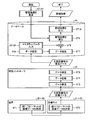
- FIG. 1 is a diagram showing a configuration of a management index calculation system 1 according to an embodiment.
- the management index calculation system 1 is a system that calculates a management index of equipment such as production equipment 310 to 330.
- the management index calculation system 1 includes production facilities 310 to 330, a general controller 20, and a database 10.
- the general controller 20 is connected to the database 10 and the production facilities 310 to 330.
- the database 10 is also connected to a display monitor 2 such as a liquid crystal monitor.
- the production facilities 310 to 330 may be referred to as the production facilities when it is not necessary to identify the production facilities 310 to 330.
- the overall controller 20 collects equipment data, which is data of the production equipments 310 to 330, from the production equipments 310 to 330 in the unified first data format, and collects the single data.
- the data processing logic converts the equipment data into element data of the second data format used for calculating the management index of the production equipments 310 to 330.
- the management index calculation system 1 since the data formats of the equipment data collected from the production equipments 310 to 330 are unified, it is possible to convert into the element data with a single processing logic.
- the overall controller 20 transmits the element data in the unified second data format to the database 10 and stores the element data in the database 10.
- the element data sent from the overall controller 20 to the database 10 has a unified data format, not the format of the data packet when sent to the database 10.
- the database 10 stores the element data in a unified second data format, and calculates the management index using the element data with a single calculation logic for each management index.
- the element data required for the management index is stored in a predetermined data format, so that the calculation logic can be easily assembled.
- the unified data format may be referred to as a unified format.
- the production facility 310 includes a facility PLC (Programmable Logic Controller) 31 and a device 41 controlled by the facility PLC 31.
- the production facility 320 includes a facility PLC 32 and a device 42 controlled by the facility PLC 32
- the production facility 330 includes a facility PLC 33 and a device 43 controlled by the facility PLC 33.
- the devices 41 to 43 may be referred to as devices when it is not necessary to identify the devices 41 to 43.
- the equipment PLCs 31 to 33 are examples of control devices arranged in the production equipments 310 to 330 that perform automated production.
- the equipment PLCs 31 to 33 control the operations of the devices 41 to 43 which are the controlled equipments arranged in the production equipments 310 to 330.
- An example of the controlled device is a robot.
- the equipment PLCs 31 to 33 use various data to control the devices 41 to 43 connected thereto, and hold data indicating the states of the devices 41 to 43.
- the equipment PLCs 31 to 33 send the equipment data requested by the general controller 20 to the general controller 20. That is, the equipment PLC 31 transmits the equipment data acquired by the device 41 to the general controller 20, the equipment PLC 32 transmits the equipment data acquired by the device 42 to the general controller 20, and the equipment PLC 33 acquires the equipment 43.
- the generated facility data is transmitted to the general controller 20.
- the equipment PLCs included in the management index calculation system 1 are not limited to the three equipments PLCs 31 to 33, and may be two or four or more. Further, each of the equipment PLCs 31 to 33 may control a plurality of devices.
- the general controller 20 collects equipment data from the equipment PLCs 31 to 33.
- the overall controller 20 collects various equipment data in a uniform format from the equipment PLCs 31 to 33 and converts the equipment data into a specific format.
- the overall controller 20 includes a communication unit 21 and a data processing unit 22.
- the communication unit 21 performs data communication with the equipment PLCs 31 to 33.
- the communication unit 21 also performs data communication with the database 10.
- the communication unit 21 receives the equipment data from the equipment PLCs 31 to 33, and transmits element data, which will be described later, which is the data after being data-processed by the data processing unit 22, to the database 10.
- the data processing unit 22 performs data processing on the equipment data sent from the equipment PLCs 31 to 33 so that it can be stored in the database 10 in a specific format, and stores the data after the data processing in the result table 103 as element data.
- the performance table 103 will be described later.
- the database 10 receives the element data from the general controller 20 from the general controller 20 and stores it.
- the database 10 calculates the management index of the production facilities 310 to 330 in which the devices 41 to 43 are arranged, using the element data and the master data registered in advance.
- the database 10 lists the collected element data based on the table definition of the master table 102 and the table definition of the actual result table 103, and calculates the management index from the list according to the management index calculation logic for calculating the management index. To do.
- the table definition defines the format for storing the master table 102 and the result table 103 in the table storage unit 12. The master table 102 will be described later.
- the database 10 outputs the calculated management index to an external device.
- the database 10 here outputs the management index to the display monitor 2 and causes the display monitor 2 to display the management index. Further, the database 10 may output the calculated management index to an information processing terminal (not shown).
- An example of the information processing terminal is a computer that manages a management index.
- the database 10 includes a table storage unit 12, a connection unit 13, a calculation unit 14, and an output unit 15. Each processing by the combination unit 13, the calculation unit 14, and the output unit 15 is executed by the database application program.
- the database application program is an application program that executes the operation of the database 10.
- the table storage unit 12 stores a master table 102 and a performance table 103.
- the master table 102 is a table that defines the format of element data to be collected, and is stored in the table storage unit 12 in advance.
- the table storage unit 12 also stores the table definitions of the master table 102 and the performance table 103.
- the performance table 103 is a table that stores the element data sent from the overall controller 20.
- the equipment data is converted into element data by data processing according to the table definition of the performance table 103.
- This element data is stored in the performance table 103. Therefore, the performance table 103 is a table that stores the element data generated according to the table definition of the performance table 103.
- the table definition of the master table 102 is also used when converting the code of the element data into a list recognizable to the user.
- the combining unit 13 extracts the element data necessary for calculating the management index requested by the user from the element data sent from the overall controller 20. Further, the combining unit 13 extracts from the master table 102 the master data necessary for calculating the management index requested by the user.
- the combining unit 13 combines the master data of the master table 102 and the extracted element data. By combining the master data of the master table 102 and the element data, the combining unit 13 associates the content of the element data with the code of the element data defined in the master table 102. Thereby, the content of the element data is specified.
- the calculating unit 14 calculates the management index requested by the user based on the data combined by the combining unit 13. The management index calculation process will be described later.
- the output unit 15 outputs the management index calculated by the calculation unit 14 to an external device such as the display monitor 2.
- the calculation unit 14 and the output unit 15 may be arranged outside the database 10.
- the database 10 can accept a request for a management index from a web application or an exe application of an information processing terminal operated by a user. Further, when the database 10 calculates the requested management index, it can output the management index to the web application or the exe application that has received the request. Therefore, the display monitor 2 may be included in the information processing terminal of the user.
- Management indicators are a set of measurement criteria that help define the degree to which an organization achieves its goals.
- the management index differs depending on the characteristics or strategy of the organization, and ISO (International Organization for Standardization) 22400 is a KPI (Key Performance Indicator) in the MES (Manufacturing Execution System) area. And is an international standard for data constituting KPI.
- ISO22400 defines KPIs in six areas: productivity, quality, capacity, environment, inventory, and maintenance.
- the management index calculation system 1 calculates a management index for each production facility.
- FIG. 2 is a diagram showing an example of the calculation formula information 201 used in the management index calculation system 1 according to the embodiment.
- FIG. 3 is a diagram showing the element information 202 used in the management index calculation system 1 according to the embodiment.
- the element information 202 of FIG. 3 indicates the definition of the element shown in FIG.
- the element information 202 indicates the correspondence between the element name and the element definition.
- the calculation formula information 201 is created based on the element information 202.
- the calculation formula information 201 is information on a calculation formula used when the calculation unit 14 calculates the management index of each production facility.
- the calculation formula information 201 is a KPI of the productivity area in the production facility, which is a calculation formula for the total efficiency, the operating rate, the time utilization rate, the performance utilization rate, and the non-defective rate, and the elements constituting these calculation equations. Shows the relationship.
- the total efficiency is the total efficiency of the production equipment, and the operating rate is the operating rate of the production equipment.
- the elements of the non-defective product rate are the number of non-defective products and the input quantity.
- the -Operating time, operating time, operating time, standard time, input quantity, and number of non-defective products are factors for each production facility, so they differ for each production facility.
- the operable time is the time when the production equipment can be operated, and the operational time is the time during which the production equipment must operate, out of the operable time of the production equipment.
- the operating time is the time during which the production facility is operating among the operating time of the production facility, and the standard time is the standard time of the production facility.
- the standard time is a time required for performing a predetermined fixed operation in each production facility.
- the input quantity is the quantity of the work put into the production facility, and the number of non-defective products is the quantity of the work satisfying a specific quality.
- the management index calculation system 1 can display the calculated value of the KPI defined in ISO22400 on the monitor of the information processing terminal.
- the database 10 included in the management index calculation system 1 executes the KPI calculation formula defined in ISO22400.
- the management index calculation system 1 has a table created based on a database application program that calculates a KPI and a table definition that defines specifications for storing specifications of element data that forms a KPI calculation formula. In the table definition, "data item”, “data type”, “key”, etc. of element data are defined.
- the database 10 has a table for storing data necessary for tabulating each element data.
- the master table 102 and the performance table 103 stored in the database 10 will be described.
- FIG. 4 is a diagram showing an example of the standard time master table definition 203A according to the embodiment
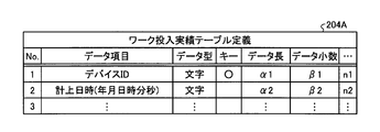
- FIG. 5 is a diagram showing an example of the work input record table definition 204A according to the embodiment
- FIG. 6 is a diagram showing an example of the operation history record table definition 205A according to the embodiment
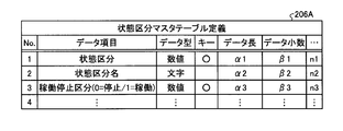
- FIG. 7 is a diagram showing an example of the state classification master table definition 206A according to the embodiment.
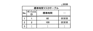
- FIG. 8 is a diagram showing an example of the standard time master table 203B according to the embodiment
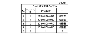
- FIG. 9 is a diagram showing an example of the work input record table 204B according to the embodiment
- FIG. 10 is a diagram showing an example of the operation history record table 205B according to the embodiment
- FIG. 11 is a diagram showing an example of the working hour master table 207 according to the embodiment.
- the table stored in the database 10 is a master table 102 that stores data in which data is defined in advance such as standard time and status classification, and devices 41 to 41 such as work input records and equipment operation history. It is divided into a performance table 103 storing the performance data of 43.
- the standard time master table 203B and the working time master table 207 are the master table 102.
- the work input record table 204B and the operation history record table 205B are the record table 103.
- the standard time master table definition 203A of FIG. 4 shows the table definition of the standard time master table 203B that stores master data of standard time.
- the work input result table definition 204A the operation history result table definition 205A
- the status classification master table definition 206A "data type" of each data item, "key” existence, "data length”, “Data decimal point” etc. are specified.
- Examples of data items in the standard time master table definition 203A are a device ID (identification) for identifying a device used in each of the production facilities 310 to 330, and standard time.
- the standard time in the standard time master table definition 203A is defined in seconds, for example.
- the "data type” is a format of data, and the example of the “data type” is a character or a numerical value.
- the "key” is a primary key used when searching for data.
- the "data length” is the length of the data, and the “data decimal number” is the number of digits after the decimal point of the data.
- the work input record table definition 204A in FIG. 5 shows the table definition of the work input record table 204B that stores the element data of the input quantity.
- Examples of data items in the work input record table definition 204A are the device ID and the accounting date and time.
- the accounting date and time indicates the date and time when the result of the work input is accounted for.
- the accounting date and time in the work input record table definition 204A is defined by year, month, day, hour, minute, and second, for example.
- the operation history record table definition 205A in FIG. 6 shows the table definition of the operation history record table 205B that stores the element data of the operation time.
- Examples of data items in the operation history record table definition 205A are device ID, state classification, change start date and time, and change end date and time.
- the status division indicates the status of the production facilities 310 to 330
- the change start date/time indicates the date/time when the state division starts changing
- the change end date/time indicates the date/time when the state classification ends changing.
- Examples of the state classifications include a work being processed state, a work input waiting state, an abnormal state, and a power-off state.
- the change start date and time and the change end date and time in the operation history record table definition 205A are defined by year, month, day, hour, minute, and second, for example.
- State classification master table definition 206A in FIG. 7 shows the table definition of the table that stores the master data of the status classification.
- Examples of data items in the status classification master table definition 206A are status classification, status classification name, and operation stop classification.
- the status classification name is the name of the status classification
- the operation stop classification indicates the operation or stop of the production facilities 310 to 330. For example, when the production facilities 310 to 330 are stopped, the operation stop category is indicated by "0", and when the production equipment is in operation, the operation stop category is indicated by "1".
- the data processing according to the performance table definition such as the work input performance table definition 204A and the operation history performance table definition 205A corresponds to the generation of the element data in the uniform format.
- the standard time master table 203B of FIG. 8 is a table for storing element data of standard time.
- the element data in the standard time master table 203B is created based on the standard time master table definition 203A.
- the device ID and the standard time are associated with each other.
- the standard time in the standard time master table 203B is indicated in seconds according to the standard in the standard time master table definition 203A.
- the work input record table 204B in FIG. 9 is a table for storing element data of the input quantity.
- the element data in the work input record table 204B is created based on the work input record table definition 204A.
- the device ID is associated with the accounting date and time.
- the accounting date and time in the work input result table 204B is indicated by year, month, day, hour, minute, and second according to the rule in the work input result table definition 204A.
- the operation history record table 205B in FIG. 10 is a table that stores element data of operation time.
- the element data in the operation history record table 205B is created based on the operation history record table definition 205A.
- the status classification, change start date and time, and change end date and time are registered for each device ID.
- the change start date and time and the change end date and time in the operation history record table 205B are indicated by year, month, day, hour, minute, and second according to the rules in the operation history record table definition 205A.
- the working hour master table 207 of FIG. 11 is a table that stores element data of working hours.
- the element data in the working hour master table 207 is created based on the master table definition corresponding to the working hour master table 207.
- the working hour name, shift start date and time, shift end date and time, operable time, and planned downtime are registered for each working hour ID.
- the working hours ID is information for identifying the working hours
- the working hours name is the name of the working hours. Examples of working hours are day and night shifts.
- the shift start date and time is the date and time when the shift work was started, and the shift end date and time is the date and time when the shift work was ended.
- the planned downtime is a time during which the production facilities 310 to 330 are stopped according to the plan.
- the table storage unit 12 stores the master table corresponding to the status classification master table definition 206A. ..
- the description of the master table definition corresponding to the working hour master table 207 is omitted, but the table storage unit 12 stores the master table definition corresponding to the working hour master table 207. ..
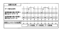
- FIG. 12 is a diagram for explaining a collection timing of facility data collected by the management index calculation system 1 according to the embodiment.
- FIG. 12 shows the processing of the devices 41 to 43 in the production facilities 310 to 330 and the processing of the general controller 20.
- the processing of the devices 41 to 43 there is shown a timing chart in which the devices 41 to 43 send the equipment data to the overall controller 20 via the equipment PLCs 31 to 33.
- the devices 41 to 43 detect that the equipment data they are handling has changed. Further, the devices 41 to 43 generate word data related to management of the device operating state, and generate bit data related to management of the device operating state. The devices 41 to 43 provide a data change signal indicating whether or not the data has changed, word data related to management of the device operating state, and bit data related to management of the device operating state at a specific timing. Send to.
- the general controller 20 collects equipment data sent from the devices 41 to 43, executes data processing that is data processing to generate element data, and stores the element data in the database 10.
- the data processing logic is defined by the sequence program, and the data format when collecting the equipment data from the production equipment 310 to 330 is defined by the allocation table of the storage area for storing the equipment data.
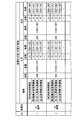
- FIG. 13 is a table showing a storage area assigned to the first equipment data sent from the equipment PLCs 31 to 33 according to the embodiment to the overall controller 20.
- FIG. 14 is a table showing a storage area assigned to the second equipment data sent from the equipment PLCs 31 to 33 according to the embodiment to the overall controller 20.
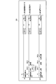
- FIG. 15 is a diagram showing an example of a sequence program 500 used when the general controller 20 according to the embodiment processes the equipment data.
- FIG. 13 and 14 show an allocation table of storage areas of facility data transmitted and received between the production facilities 310 to 330 and the general controller 20. Specifically, in FIG. 13, the addresses in the first allocation area of the memory device are shown as the allocation area of the equipment data for each device, and in FIG. 14, the addresses of the memory device are allocated as the allocation area of the equipment data for each device. Addresses in the second allocation area are shown. In FIG. 13, (1) indicates that it is within the first allocation area, and (2) indicates that it is within the second allocation area in FIG. 14. Therefore, (1) 000 to 0FF indicates the range of 000 to 0FF in the first allocation area, and (2) 000 to 0FF indicates the range of 000 to 0FF in the second allocation area.
- the data content of the equipment data, the range in the storage area for storing the equipment data, the number of points of the stored equipment data, etc. are set.
- the range within the storage area for storing equipment data is defined by the address of the storage area for storing equipment data. It can be said that the range within the storage area for storing the facility data defines the data amount of the facility data.
- the amount of equipment data corresponds to the number of digits of equipment data.
- the data content of the equipment data is the purpose of the equipment data and is indicated by the functions used in the devices 41 to 43. Collecting the facility data according to the allocation tables of FIGS. 13 and 14 corresponds to generating the facility data in a unified format.
- the allocation table of FIG. 13 is an allocation table for storing equipment data in bit data
- the allocation table of FIG. 14 is an allocation table for storing equipment data in word data. Bit data is represented by "0" or "1", and word data is represented by 16 bits.
- the sequence program 500 is a program used when generating element data for calculating the performance utilization rate by data processing.
- the equipment data used in the sequence program 500 is obtained from the equipments 41 to 43 in the production equipments 310 to 330 by the equipments PLCs 31 to 33, and is transmitted from the equipments PLCs 31 to 33 to the general controller 20 in the format shown in FIG. Sent.
- the facility data defined in FIG. 13 is sent to the overall controller 20 as bit data, and the facility data defined in FIG. 14 is sent to the overall controller 20 as word data.
- the equipment data sent from the equipment PLCs 31 to 33 to the overall controller 20 is equipment data of the functions of the devices 41 to 43.
- the facility data of each function includes facility data input to the function and facility data output from the function.
- the example of the equipment data input from the general controller 20 to the equipment PLCs 31 to 33 is the data of the time synchronization function
- the example of the equipment data sent from the equipment PLCs 31 to 33 to the general controller 20 is the data of the input result collection function, the quality information. It is the data of the collection function.
- the time synchronization function is a function of synchronizing the internal clocks of the devices 41 to 43 and the internal clock of the general controller 20.
- the input result collection function is a function of collecting the result information of the works input to the devices 41 to 43.
- the quality information collecting function is a function of collecting quality information of the works processed by the devices 41 to 43.
- the allocation table of FIG. 13 includes a bit data storage address for storing equipment data required for the sequence program 500.
- the equipment data necessary for the sequence program 500 is equipment data related to the operation preparation of the A1 device and the A2 device, the system lock, and the like.
- the bit data storage address of the equipment data related to the A1 device operation preparation, system lock, etc. is (1) 010 to 01F assigned to the equipment data of the operating state management function, and the A2 device operation preparation, system lock, etc.
- the bit data storage addresses of the equipment data related to (1) are 110 to 11F assigned to the equipment data of the operating state management function.
- the A1 device and the A2 device are any of the devices 41 to 43, respectively.
- the allocation table of FIG. 14 includes a device ID storage address (not shown) that stores a device ID for identifying the devices 41 to 43.
- the points of the address where the facility data is registered and the range of the address where the facility data is registered are set for the devices 41 to 43. Further, for each function, the score of the address where the facility data is registered and the range of the address where the facility data is registered are set. For example, 16 addresses are set for each facility data input to each function of the A1 device, and 256 addresses are set for each facility data input for all functions of the A1 device. In this way, in the management index calculation system 1, the allocation position of the equipment data to each function is set.
- the devices 41 to 43 send the equipment data in the uniform format shown in FIGS. 13 and 14 to the overall controller 20 via the equipment PLCs 31 to 33.
- the user of the management index calculation system 1 defines a uniform format for the facility data of each function shown in FIG. 13 or 14 so that the management index calculation system 1 calculates the management index.
- This unified format is set in the devices 41 to 43.
- the devices 41 to 43 can send the equipment data in the set uniform format to the overall controller 20, and the overall controller 20 collects the equipment data from each of the devices 41 to 43 in the same data format. be able to.
- FIG. 16 is a diagram showing the content information of the facility data collected by the general controller 20 according to the embodiment.
- FIG. 16 shows the correspondence between the address in the second allocation area shown in FIG. 14 and the contents of the equipment data registered at this address.
- the devices 41 to 43 send the facility data to the overall controller 20 according to the correspondence relationship shown in FIG.
- Addresses 830 to 835 shown in FIG. 16 are all areas in which facility data of the quality information collecting function is stored. For example, at the address 830 in the second area, the determination result flag corresponding to the characteristic 1 of the quality information collecting function is stored. The determination result flag indicates the result of determination made on the characteristic 1 related to the quality information collecting function.
- the collected data items such as the judgment result flag, the number of continuous tests, and the result value which is a characteristic value are patterned. Further, in the present embodiment, data items are collected in the same pattern for each quality characteristic.
- the number of continuous tests is the number of continuous tests in the quality test.
- the characteristic value is the result of the quality test and indicates the characteristic of the work as a product.
- the facility data allocation table may be provided with a device-specific storage area for storing data that is not related to management indexes and that is desired to be collected by the device. Since the user can set the device-specific data type, storage address, storage data amount, and data content in the device-specific storage area, the overall controller 20 collects data unique to each device. It becomes possible to do.
- the device-specific storage area is used, by registering the setting contents in the master table 102, the device-specific data collected in the database 10 can be easily confirmed after collection.
- the equipment data of functions such as the quality information collection function or the device-specific data may differ in the amount of data to be acquired for each device.
- the allocation area of the function not used by the device may be deleted, and a part or all of the deleted allocation area may be used as the allocation area of the function that is uniquely used by the device. That is, it is possible to increase or decrease the allocation area of each function in each device.
- the allocation area of the function not used in any of the devices may be deleted, and a part or all of the deleted allocation area may be used as the allocation area of the other device. As a result, the allocation area of each device can be increased or decreased.
- the allocation area of each device can be increased or decreased.
- the overall controller 20 executes the sequence program 500 according to the data allocation table shown in FIGS. 13 and 14.
- the line indicated by (0) in the sequence program 500 is the case where the power supply of the device is OFF. Further, the line indicated by (60) in the sequence program 500 is the case where the device is in the adjustment, and the line indicated by (67) in the sequence program 500 is the case when the device is processing the work.
- the location of “MOV K1 D0” in the sequence program 500 is the process of writing “1” in decimal notation to the area of D0 where the status classification is stored. Therefore, when the power of the device is OFF, "1" is written as the status classification.
- the portion of “MOV K2 D0” in the sequence program 500 is a process of writing “2” in decimal notation to the area of D0 in which the status classification is stored. Therefore, when the device is under adjustment, "2” is written as the status classification.
- the portion of “MOV K3 D0” in the sequence program 500 is a process of writing “3” in decimal to the area of D0 in which the status classification is stored. Therefore, when the device is processing a workpiece, "3" is written as the status classification.
- FIG. 17 is a diagram for explaining an operation processing procedure of the management index calculation system 1 according to the embodiment.
- the master table 102 is input in advance to the database 10 by the user (step ST100).
- the equipment PLCs 31 to 33 operate according to their sequence programs. That is, the equipment PLCs 31 to 33 control the devices 41 to 43 based on the respective sequence programs.
- the equipment data required to calculate the management index is acquired by each of the devices 41 to 43 as equipment data in a unified format in the form of an allocation table as shown in FIG. 13 or FIG. 14 (step ST1).
- the equipment data acquired by each of the devices 41 to 43 is transmitted to the overall controller 20 by the equipment PLCs 31 to 33 according to the data transmission timing chart shown in FIG. 12 (step ST2).
- the equipment PLC 31 transmits the equipment data acquired by the device 41 to the overall controller 20
- the equipment PLC 32 transmits the equipment data acquired by the device 42 to the overall controller 20
- the equipment PLC 33 transmits the equipment data.
- the facility data acquired in 43 is transmitted to the overall controller 20.
- the equipment PLCs 31 to 33 transmit the equipment data of their own equipment to the overall controller 20 based on the allocation table in the unified format and the timing chart of FIG. 12, regardless of the management index request from the user.
- the timing chart used by the equipment PLCs 31 to 33 may be a timing chart in which the production equipments 310 to 330 collect data in response to a data request from the general controller 20.
- the general controller 20 receives the facility data for each production facility from the production facilities 310 to 330 (step ST3).
- the overall controller 20 extracts the equipment data necessary for provision to the database 10 from the equipment data in the uniform format collected from each of the production equipment 310 to 330 based on the sequence program 500 shown in FIG.
- the overall controller 20 performs data processing in accordance with the table definition of the performance table 103 of the database 10 (step ST4), and sends it to each performance table 103 of the database 10 as element data (step ST5). That is, the overall controller 20 makes the element data in a form according to the data item, the data format, and the number of digits defined by the table definition of the performance table 103 that stores the element data for the database 10 to calculate the management index. Data processing is performed on the equipment data, and the data is transmitted to the performance table 103 of the database 10.
- the database 10 receives the element data for each production facility from the overall controller 20 (step ST6) and stores the element data in the area in the performance table 103 corresponding to the element data.
- the equipment PLCs 31 to 33 use the device ID data, which is the individual identification management number of its own device, as the device ID storage address of the allocation table described in FIG. Store in the indicated area. Further, the equipment PLCs 31 to 33 transmit the equipment data for operation preparation necessary for the sequence program 500 and the equipment data in bits such as the number of seconds of system lock to the area indicated by the bit data storage address of the allocation table described in FIG. Store.
- the overall controller 20 uses the sequence program 500 to determine the status classification of each production facility 310 to 330 from the facility data stored by each production facility 310 to 330.
- the overall controller 20 stores the device ID, the number indicating the state classification, the change start date and time, the change end date and time, and other necessary data stored from each of the production facilities 310 to 330, at the time when the state classification has changed. Are collectively stored in the operation history record table 205B of the database 10.
- the central controller 20 collects data from a plurality of production facilities 310 to 330 simultaneously in parallel, the plurality of production facilities may be one management unit. That is, the overall controller 20 may generate element data for each of a plurality of production facilities from the facility data collected from the production facilities 310 to 330 and store the element data in the database 10. For example, the overall controller 20 regards the process of three A1 devices, A2 devices, and A3 devices arranged in different production facilities of the same type as the A process, and the three processes of the A1 device, A2 device, and A3 device. When the equipment status classification is in operation, the process A may be in operation.
- the general controller 20 by setting a new sequence program with a plurality of production facilities as one management unit, the general controller 20 generates the facility data of the state classification of the process A, and the respective production facilities 310 to 330.
- the operation history record table 205B can be stored in the same manner as the operation history of the above.
- the user operates the web application or the exe application from the information processing terminal to obtain information on the management index of the production equipment 310 to 330 in the daily management work of the production equipment 310 to 330, and requests the management index,
- the production index corresponding to the management index and the period of the management index are designated, and the management index is requested to the database 10 (step ST101).
- the combining unit 13 extracts the element data necessary for calculating the management index of the requested production equipment and period from the performance table 103 (step ST7). .. Then, the combining unit 13 of the database 10 combines the master data of the master table 102 previously input by the user with the element data (step ST8). Specifically, the combining unit 13 converts the code of the element data into data according to the master data of the master table 102. The combining unit 13 enables the content of the element data to be specified by associating the content of the element data with the content defined in the master table 102. As a result, the data in the list can be confirmed by the user as to the content of the element data indicated by the code.
- the calculation unit 14 calculates the management index requested by the user based on the combined data (step ST9).
- the output unit 15 outputs the calculated value of the management index to the web application or the exe application of the information processing terminal operated by the user (step ST10). As a result, the management index designated by the user is displayed on the monitor or the like of the information processing terminal.
- the connection unit 13 of the database 10 extracts the element data used for calculating the equipment operating time of the device 41 from the operation history record table 205B based on the operation history record table definition 205A.
- the device ID is “1”
- the equipment state classification is “1” indicating that the operation is in progress
- the change end date and time is after Jan. 10, 2018 8:00 and the change start date and time is 2018.
- the element data before 17:00 on January 10, 2010 is extracted.
- the combining unit 13 may extract element data whose operation stop classification is "1" indicating that the operation stop is in operation.
- the calculating unit 14 uses the element data extracted by the combining unit 13 to set the device ID to “1”, the equipment state classification to “1” indicating that the device is in operation, and the change end date and time is January 2018. After 8:00 on the 10th, the total sum of the times of the element data whose change start date and time is before 17:00 on January 10, 2018 is calculated.
- the coupling unit 13 extracts the element data for calculating the quantity input to the device 41 from the work input result table 204B based on the work input result table definition 204A, and the calculation unit 14 based on the extraction result. Then, the quantity input to the device 41 is calculated.
- the combining unit 13 here extracts the element data whose device ID is “1” and whose work accounting date is from 8:00 to 17:00 on January 10, 2018, and displays the number of extracted data items.
- the calculation unit 14 totals. Since one work accounting date and time is registered each time one work is input, the number of data items and the input amount are equal. Therefore, the calculation unit 14 handles the total number of data cases as the input quantity.
- the combining unit 13 extracts the master data of the standard time of the device 41 from the standard time master table 203B based on the standard time master table definition 203A.
- the combining unit 13 here extracts the standard time with the device ID “1”.
- the calculation unit 14 calculates the performance operation rate according to the KPI calculation formula using the standard time, the operation time, and the input quantity. Specifically, the calculation unit 14 calculates the performance operation rate by dividing the product of the standard time and the input quantity by the operation time.
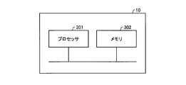
- FIG. 18 is a diagram illustrating a hardware configuration example of the database 10 according to the embodiment.
- the database 10 can be realized by the processor 301 and the memory 302 shown in FIG.
- the processor 301 are a CPU (Central Processing Unit, a central processing unit, a processing unit, an arithmetic unit, a microprocessor, a microcomputer, a processor, also called a DSP (Digital Signal Processor)) or a system LSI (Large Scale Integration).
- Examples of the memory 302 are RAM (Random Access Memory) and ROM (Read Only Memory).
- the database 10 is realized by the processor 301 reading and executing a database application program for executing the operation of the database 10 stored in the memory 302. It can also be said that this database application program causes a computer to execute the procedure or method of the database 10.
- the memory 302 is also used as a temporary memory when the processor 301 executes various processes.
- the functions of the database 10 may be partially realized by dedicated hardware and partially realized by software or firmware. Further, the general controller 20 and the equipment PLCs 31 to 33 may be realized by the processor 301 and the memory 302 shown in FIG.
- the general controller 20 receives various pieces of equipment data in a uniform format from each of the production equipment 310 having the equipment PLC 31, the production equipment 320 having the equipment PLC 32, and the production equipment 330 having the equipment PLC 33. To collect.
- the management index calculation system 1 uses a single data processing logic to convert the collected equipment data into a data format according to the master table 102, and stores it as element data of the performance table 103.
- the overall controller 20 since the plurality of production equipments 310 to 330 transmit the equipment data in the uniform format to the overall controller 20, the overall controller 20 has the unified format sent from each of the production equipments 310 to 330.
- the equipment data may be processed by a single data processing logic and stored in the database 10 as element data.
- the database 10 may calculate the management index by a single calculation logic for each management index based on the element data stored by the overall controller 20 and unified regardless of the types of the production facilities 310 to 330. ..
- the burden of data processing and management index calculation is suppressed, and one management index calculation system 1 can easily calculate the management indexes of many different types of production equipment.
- the management index calculation system 1 uses the unified data format to unify the data storage area, data format, and number of digits for the data items required to calculate the management index.
- the management index calculation system 1 has a fixed data storage area and data pattern for quality data having different items for each production facility, and the number of data items, the data format, and the number of digits are variable.
- the management index calculation system 1 provides a data area in which the data pattern, the data format, the number of digits, etc. can be freely set in the data format for the data items that are acquired for each production equipment and differ for each production equipment. ..
- the overall controller 20 can combine various equipment data of the production equipments 310 to 330 to be managed by collecting various equipment data from the production equipments 310 to 330 in real time and processing the data.
- the general controller 20 can easily generate element data of a process or line in units of a plurality of production facilities and store it in the database 10.
- the database 10 does not need to generate element data in units of a plurality of production facilities from stored history data for each production facility, and manages the data based on the stored element data in units of a plurality of production facilities.
- the management index can be calculated by the index calculation logic. Therefore, the processing load on the database 10 is suppressed, and the management index can be efficiently calculated and output. Further, by separating the facility data storage function and management function, which are the original functions of the database 10, from the management index calculation function, the management index calculation system 1 can be easily constructed.
- the general controller 20 collects the facility data generated from the production facilities 310 to 330 in the unified data format, and uses the single data processing logic to calculate the facility data. Converted to element data to be used. Further, the database 10 stores the element data from the general controller 20 in the data storage area in a unified data format, and manages the element data in the data storage area with a single calculation logic for each management index. The index is calculated. As a result, the management index calculation system 1 can easily collect the facility data and easily acquire the element data, and thus can easily calculate the management index.
- 1 management index calculation system 1 display monitor, 10 database, 12 table storage section, 13 combination section, 14 calculation section, 15 output section, 20 integrated controller, 21 communication section, 22 data processing section, 31-33 equipment PLC, 41 ⁇ 43 device, 102 master table, 103 result table, 201 calculation formula information, 202 element information, 203A standard time master table definition, 203B standard time master table, 204A work input result table definition, 204B work input result table, 205A operation history Actual table definition, 205B operation history actual table, 206A status classification master table definition, 207 working hour master table, 310-330 production equipment, 500 sequence program.
Landscapes
- Engineering & Computer Science (AREA)
- Physics & Mathematics (AREA)
- General Physics & Mathematics (AREA)
- Automation & Control Theory (AREA)
- General Engineering & Computer Science (AREA)
- Manufacturing & Machinery (AREA)
- Quality & Reliability (AREA)
- General Factory Administration (AREA)
- Testing And Monitoring For Control Systems (AREA)
Abstract
La présente invention concerne un système de calcul d'indice de gestion (1) comportant : une pluralité d'installations de production (310 à 330) qui comprennent un dispositif et un dispositif de commande servant à commander le dispositif ; un contrôleur général (20) servant à collecter à partir de chaque installation de la pluralité d'installations de production (310 à 330) des données d'installation qui sont des données des installations de production (310 à 330), qui sont générées dans un premier format de données unifié entre la pluralité d'installations de production (310 à 330) et de façon à devenir un second format de données unifié entre la pluralité d'installations de production (310 à 330), et à convertir les données d'installation du premier format de données à l'aide d'une logique de traitement commune à chaque élément de données des données d'installation collectées à partir de la pluralité d'installations de production (310 à 330) en des données élémentaires utilisées pour le calcul de l'indice de gestion de la pluralité d'installations de production (310 à 330) ; et une base de données (10) servant à stocker les données élémentaires du second format de données dans une zone de stockage de données, et à calculer l'indice de gestion à l'aide de la logique de calcul de chaque indice de gestion en utilisant les données élémentaires dans la zone de stockage de données.
Priority Applications (3)
| Application Number | Priority Date | Filing Date | Title |
|---|---|---|---|
| PCT/JP2018/045577 WO2020121422A1 (fr) | 2018-12-11 | 2018-12-11 | Système et procédé de calcul de valeur d'indice de gestion |
| JP2019531845A JP6625286B1 (ja) | 2018-12-11 | 2018-12-11 | 管理指標算出システムおよび管理指標算出方法 |
| CN201880100014.7A CN113168160A (zh) | 2018-12-11 | 2018-12-11 | 管理指标计算系统及管理指标计算方法 |
Applications Claiming Priority (1)
| Application Number | Priority Date | Filing Date | Title |
|---|---|---|---|
| PCT/JP2018/045577 WO2020121422A1 (fr) | 2018-12-11 | 2018-12-11 | Système et procédé de calcul de valeur d'indice de gestion |
Publications (1)
| Publication Number | Publication Date |
|---|---|
| WO2020121422A1 true WO2020121422A1 (fr) | 2020-06-18 |
Family
ID=69100985
Family Applications (1)
| Application Number | Title | Priority Date | Filing Date |
|---|---|---|---|
| PCT/JP2018/045577 Ceased WO2020121422A1 (fr) | 2018-12-11 | 2018-12-11 | Système et procédé de calcul de valeur d'indice de gestion |
Country Status (3)
| Country | Link |
|---|---|
| JP (1) | JP6625286B1 (fr) |
| CN (1) | CN113168160A (fr) |
| WO (1) | WO2020121422A1 (fr) |
Cited By (1)
| Publication number | Priority date | Publication date | Assignee | Title |
|---|---|---|---|---|
| CN115698885A (zh) * | 2020-06-30 | 2023-02-03 | 日本电产株式会社 | 错误分析装置 |
Citations (6)
| Publication number | Priority date | Publication date | Assignee | Title |
|---|---|---|---|---|
| JP2009169882A (ja) * | 2008-01-21 | 2009-07-30 | Yamatake Corp | データ管理装置、データ管理方法、及びデータ管理プログラム |
| US20110060427A1 (en) * | 2009-09-09 | 2011-03-10 | Batke Brian A | Diagnostic Module For Distributed Industrial Network Including Industrial Control Devices |
| US20130282333A1 (en) * | 2012-04-23 | 2013-10-24 | Abb Technology Ag | Service port explorer |
| JP2016170460A (ja) * | 2015-03-11 | 2016-09-23 | 株式会社日立産機システム | 生産管理システム及び生産管理方法 |
| WO2018138877A1 (fr) * | 2017-01-27 | 2018-08-02 | 三菱電機株式会社 | Dispositif et procédé de gestion |
| JP2018523226A (ja) * | 2015-06-30 | 2018-08-16 | ▲隣▼元科技(北京)有限公司 | 分布式計算ネットワークシステムおよび当該システムに用いられる計算ノード |
Family Cites Families (6)
| Publication number | Priority date | Publication date | Assignee | Title |
|---|---|---|---|---|
| JP2001249717A (ja) * | 2000-03-07 | 2001-09-14 | Toshiba Corp | リモート管理センターおよび広域設備保全管理システム |
| CN103914753A (zh) * | 2014-03-12 | 2014-07-09 | 云南电力试验研究院(集团)有限公司电力研究院 | 一种输变电设备绩效管理kpi指标系统 |
| TWI571810B (zh) * | 2014-12-01 | 2017-02-21 | 財團法人資訊工業策進會 | 生產效能管理裝置及其生產效能管理方法 |
| EP3029617A1 (fr) * | 2014-12-01 | 2016-06-08 | Institute for Imformation Industry | Dispositif de gestion de performance de production et procédé de gestion de telles performances |
| JP6350735B2 (ja) * | 2015-02-18 | 2018-07-04 | 東芝三菱電機産業システム株式会社 | 鉄鋼プラントアラームマネジメント装置 |
| CN108873823B (zh) * | 2017-05-10 | 2021-08-20 | 台达电子企业管理(上海)有限公司 | 数据管理和传输系统 |
-
2018
- 2018-12-11 WO PCT/JP2018/045577 patent/WO2020121422A1/fr not_active Ceased
- 2018-12-11 CN CN201880100014.7A patent/CN113168160A/zh active Pending
- 2018-12-11 JP JP2019531845A patent/JP6625286B1/ja active Active
Patent Citations (6)
| Publication number | Priority date | Publication date | Assignee | Title |
|---|---|---|---|---|
| JP2009169882A (ja) * | 2008-01-21 | 2009-07-30 | Yamatake Corp | データ管理装置、データ管理方法、及びデータ管理プログラム |
| US20110060427A1 (en) * | 2009-09-09 | 2011-03-10 | Batke Brian A | Diagnostic Module For Distributed Industrial Network Including Industrial Control Devices |
| US20130282333A1 (en) * | 2012-04-23 | 2013-10-24 | Abb Technology Ag | Service port explorer |
| JP2016170460A (ja) * | 2015-03-11 | 2016-09-23 | 株式会社日立産機システム | 生産管理システム及び生産管理方法 |
| JP2018523226A (ja) * | 2015-06-30 | 2018-08-16 | ▲隣▼元科技(北京)有限公司 | 分布式計算ネットワークシステムおよび当該システムに用いられる計算ノード |
| WO2018138877A1 (fr) * | 2017-01-27 | 2018-08-02 | 三菱電機株式会社 | Dispositif et procédé de gestion |
Cited By (1)
| Publication number | Priority date | Publication date | Assignee | Title |
|---|---|---|---|---|
| CN115698885A (zh) * | 2020-06-30 | 2023-02-03 | 日本电产株式会社 | 错误分析装置 |
Also Published As
| Publication number | Publication date |
|---|---|
| CN113168160A (zh) | 2021-07-23 |
| JP6625286B1 (ja) | 2019-12-25 |
| JPWO2020121422A1 (ja) | 2021-02-15 |
Similar Documents
| Publication | Publication Date | Title |
|---|---|---|
| JP7014643B2 (ja) | 情報収集システム | |
| CN104766147B (zh) | 智能设备管理方法及管理系统 | |
| JP4982196B2 (ja) | 交換部品発注処理装置、交換部品発注処理方法及び交換部品発注処理プログラム | |
| JP2000176799A (ja) | 生産製造計画システム | |
| JP2019153051A5 (fr) | ||
| JP5327239B2 (ja) | データ収集装置、並びに、該データ収集装置の制御方法および制御プログラム | |
| JP2014026415A (ja) | 発注支援装置、発注支援方法および生産管理システム | |
| JP2012247964A (ja) | 進捗管理装置、及び進捗管理プログラム | |
| CN101763581A (zh) | 发电厂eam系统和该系统的报表管理模块 | |
| CN114819640A (zh) | 一种精密铸造行业生产管理自动排产处理系统 | |
| JP7210982B2 (ja) | 情報処理装置、情報処理方法、およびプログラム | |
| JP6908201B1 (ja) | データ処理装置、アセット管理装置、及び保守部品管理装置 | |
| US10222788B2 (en) | Plan generating device and plan generating method | |
| JP6625286B1 (ja) | 管理指標算出システムおよび管理指標算出方法 | |
| JP7348051B2 (ja) | 作業指示システムおよび作業指示方法 | |
| JP4332164B2 (ja) | 作業性管理システム、作業性管理方法および作業性管理プログラム | |
| CN101763579A (zh) | 发电厂的设备管理系统 | |
| JP7460233B2 (ja) | 情報処理装置、情報処理方法、プログラム、およびデータ構造 | |
| JP2010272063A (ja) | 作業時間集計システムおよび作業時間集計方法 | |
| JPH08147356A (ja) | 保全管理装置 | |
| JP2021174227A (ja) | 生産情報管理方法、生産情報管理システム、及び、生産方法 | |
| KR102466301B1 (ko) | 제품-작업자 맞춤형 스마트 팩토리 플랫폼 운용 방법 및 운용 서버 | |
| JP2023113707A (ja) | データ構造および情報収集システム | |
| CN117436625A (zh) | 一种生产排程管理方法、系统、设备及介质 | |
| KR20020085907A (ko) | 공정명세서를 이용한 현장 자동 주문판단방법 |
Legal Events
| Date | Code | Title | Description |
|---|---|---|---|
| ENP | Entry into the national phase |
Ref document number: 2019531845 Country of ref document: JP Kind code of ref document: A |
|
| 121 | Ep: the epo has been informed by wipo that ep was designated in this application |
Ref document number: 18942815 Country of ref document: EP Kind code of ref document: A1 |
|
| NENP | Non-entry into the national phase |
Ref country code: DE |
|
| 122 | Ep: pct application non-entry in european phase |
Ref document number: 18942815 Country of ref document: EP Kind code of ref document: A1 |