WO2020121430A1 - Échantillonneur automatique pour chromatographe - Google Patents
Échantillonneur automatique pour chromatographe Download PDFInfo
- Publication number
- WO2020121430A1 WO2020121430A1 PCT/JP2018/045642 JP2018045642W WO2020121430A1 WO 2020121430 A1 WO2020121430 A1 WO 2020121430A1 JP 2018045642 W JP2018045642 W JP 2018045642W WO 2020121430 A1 WO2020121430 A1 WO 2020121430A1
- Authority
- WO
- WIPO (PCT)
- Prior art keywords
- needle
- pipe
- injection port
- housing
- wide component
- Prior art date
- Legal status (The legal status is an assumption and is not a legal conclusion. Google has not performed a legal analysis and makes no representation as to the accuracy of the status listed.)
- Ceased
Links
Images

Classifications
-
- G—PHYSICS
- G01—MEASURING; TESTING
- G01N—INVESTIGATING OR ANALYSING MATERIALS BY DETERMINING THEIR CHEMICAL OR PHYSICAL PROPERTIES
- G01N30/00—Investigating or analysing materials by separation into components using adsorption, absorption or similar phenomena or using ion-exchange, e.g. chromatography or field flow fractionation
- G01N30/02—Column chromatography
- G01N30/04—Preparation or injection of sample to be analysed
- G01N30/24—Automatic injection systems
-
- G—PHYSICS
- G01—MEASURING; TESTING
- G01N—INVESTIGATING OR ANALYSING MATERIALS BY DETERMINING THEIR CHEMICAL OR PHYSICAL PROPERTIES
- G01N30/00—Investigating or analysing materials by separation into components using adsorption, absorption or similar phenomena or using ion-exchange, e.g. chromatography or field flow fractionation
- G01N30/02—Column chromatography
- G01N30/04—Preparation or injection of sample to be analysed
- G01N30/16—Injection
- G01N30/18—Injection using a septum or microsyringe
-
- G—PHYSICS
- G01—MEASURING; TESTING
- G01N—INVESTIGATING OR ANALYSING MATERIALS BY DETERMINING THEIR CHEMICAL OR PHYSICAL PROPERTIES
- G01N30/00—Investigating or analysing materials by separation into components using adsorption, absorption or similar phenomena or using ion-exchange, e.g. chromatography or field flow fractionation
- G01N30/02—Column chromatography
- G01N30/04—Preparation or injection of sample to be analysed
- G01N30/16—Injection
- G01N30/20—Injection using a sampling valve
-
- G—PHYSICS
- G01—MEASURING; TESTING
- G01N—INVESTIGATING OR ANALYSING MATERIALS BY DETERMINING THEIR CHEMICAL OR PHYSICAL PROPERTIES
- G01N30/00—Investigating or analysing materials by separation into components using adsorption, absorption or similar phenomena or using ion-exchange, e.g. chromatography or field flow fractionation
- G01N30/02—Column chromatography
- G01N30/04—Preparation or injection of sample to be analysed
- G01N30/16—Injection
- G01N30/18—Injection using a septum or microsyringe
- G01N2030/185—Injection using a septum or microsyringe specially adapted to seal the inlet
-
- G—PHYSICS
- G01—MEASURING; TESTING
- G01N—INVESTIGATING OR ANALYSING MATERIALS BY DETERMINING THEIR CHEMICAL OR PHYSICAL PROPERTIES
- G01N30/00—Investigating or analysing materials by separation into components using adsorption, absorption or similar phenomena or using ion-exchange, e.g. chromatography or field flow fractionation
- G01N30/02—Column chromatography
- G01N30/04—Preparation or injection of sample to be analysed
- G01N30/16—Injection
- G01N30/20—Injection using a sampling valve
- G01N2030/207—Injection using a sampling valve with metering cavity, e.g. sample loop
Definitions
- the present invention relates to an autosampler used for chromatographs such as liquid chromatographs and supercritical fluid chromatographs.
- an autosampler that automatically injects a sample into the analysis channel through which the mobile phase flows is often used.
- the autosampler is a switching valve for switching the flow channel configuration, a sampling needle, a syringe pump for sucking liquid through the needle, and an injection port for injecting the sample sucked from the needle tip into the analysis flow channel. And the like (see Patent Document 1).
- the injection port of the autosampler has an opening on the top surface, and the needle is inserted through the opening to fluidly connect the needle and another flow path.
- the injection port is provided with a needle seal for maintaining the liquid tightness of the connection portion with the needle inserted through the opening on the upper surface.
- Such an injection port can be directly provided in the switching valve, but if this is done, the structure of the switching valve becomes complicated and the housing of the switching valve needs to be subjected to difficult processing, resulting in an increase in cost. Therefore, there may be a case where the injection port is provided separately from the switching valve and the port of the switching valve and the injection port are fluidly connected via a pipe.
- connection method using a mail nut and a ferrule is generally used as a connection method between the pipe and the needle seal.
- this method since the worker needs to fasten the nut while pressing the end face of the pipe against the needle seal, there is a gap that becomes a dead volume between the end face of the pipe and the needle seal depending on the skill level of the worker. there is a possibility.
- the piping that connects the injection port and the port of the switching valve may be replaced with one with a different inner diameter depending on the sample and analysis conditions, so it should be easily removable from the injection port. Is desired.
- an object of the present invention is to reliably bring the end surface of the pipe into close contact with the needle seal of the injection port, and to easily attach and detach the pipe to and from the injection port.
- the present invention relates to a chromatograph autosampler for injecting a sample into a chromatography analysis channel.
- the chromatograph autosampler of the present invention has a sampling needle that moves in a state in which the tip is directed vertically downward, and a plurality of ports to which a flow path that constitutes the chromatograph is connected, and between these ports.
- a switching valve for switching the flow path configuration by switching the connection state of, and having an opening on the upper surface for fluidly connecting the needle to a pipe leading to one port of the switching valve by inserting the needle from the tip
- An injection port having a needle seal for contacting the outer peripheral surface of the tip when the tip of the needle is inserted from the opening to fluidly connect the needle and the pipe in a fluid-tight manner
- the pipe has an end surface on the injection port side facing vertically upward, a wide component is fixed to an end on the injection port side, and the end face of the pipe is exposed on an upper surface of the wide component
- the injection port has a casing having a recess for fitting and accommodating the wide component fixed to the end portion of the pipe from above, and a through hole forming the opening, and is attached to the casing.
- a cap the needle seal is disposed on the upper surface of the wide component fitted in the recess of the housing, and the needle seal is attached to the end surface of the pipe by the cap attached to the housing. It is configured to
- the end surface of the pipe is "exposed" on the upper surface of the wide component, the end surface of the pipe is in the same plane as the upper surface of the wide component, or the end surface of the pipe is the wide component. Means protruding from the upper surface of the.
- the end surface of the pipe for fluidly connecting the port of the switching valve and the injection port is directed vertically upward, and the end of the pipe on the injection port side is oriented vertically upward.
- a wide component is fixed to the upper end of the pipe, and the end face of the pipe is exposed on the upper surface of the wide component, and the housing of the injection port is provided with a recess for accommodating and storing the wide component from above.
- the needle seal is arranged on the upper surface of the wide component fitted in the recess of the housing, and the needle seal is pressed against the end surface of the pipe by a cap attached to the housing. Is configured.
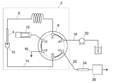
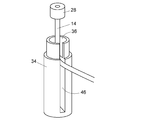
- FIG. 1 It is a block diagram which shows schematically one Example of the autosampler for chromatographs. It is sectional drawing which shows the structure of the injection port in the Example. It is a perspective view showing appearance of an injection port in the example.
- the autosampler 2 mainly includes a sampling needle 4, a sample loop 6, a switching valve 8, a syringe pump 10, and an injection port 12.
- the needle 4 has a tip and a base end, and is for inhaling the sample from the tip facing vertically downward.
- One end of the sample loop 6 is fluidly connected to the base end of the needle 4.
- the sample loop 6 is a flow path for holding the sample sucked from the tip of the needle 4, and the other end opposite to the needle 4 is fluidly connected to one port (1) of the switching valve 8. It is connected.
- the needle 4 is moved in the vertical direction and in the horizontal plane by a moving mechanism (not shown).
- the switching valve 8 is for switching the flow path configuration, and a 6-port valve is used in this embodiment.
- a syringe pump 10 In addition to the sample loop 6, a syringe pump 10, a pipe 14 leading to the injection port 12, a drain channel 16, a mobile phase supply channel 18, and an analysis channel 22 are connected to each port of the switching valve 8.
- the mobile phase supply channel 18 is a channel for supplying the mobile phase by the liquid feed pump 20.
- the analysis channel 22 is a channel in which a separation column 24 and a detector 26 are provided.
- the switching valve 8 has a state in which the mobile phase supply flow channel 18 and the analysis flow channel 22 are directly connected (a state in which the ports (5) and (6) are in communication) and a mobile phase supply flow channel 18 For interposing the sample loop 6 and the needle 4 between the sample and the analysis channel 22 (ports (1)-(6), (2)-(3), (4)-(5)). It is possible to switch to any one of (the state of FIG. 1 in which they are communicated).
- the syringe pump 10 is provided so as to be in fluid communication with the needle 4 through the sample loop 6 by the switching valve 8, and is for inhaling the sample through the needle 4.
- the injection port 12 is in fluid communication with one port of the switching valve 8 via the pipe 14, and is used for guiding the sample sucked from the tip of the needle 4 and held in the sample loop 6 to the analysis channel 22. It is a thing.
- the injection port 12 has an opening 32 for inserting the needle 4 from above, and makes the needle 4 inserted from the opening 32 fluidly communicate with a pipe 14 leading to one port (4) of the switching valve 8. Is.
- the injection port 12 includes a housing 34, a needle seal 38, a spacer 40 and a cap 42.
- the end of the pipe 14 on the injection port 12 side is held in the housing 34 of the injection port 12 with the end surface 15 facing vertically upward.
- a wide component 28 having a cylindrical shape and made of metal is fixed to the outer peripheral surface of the end of the pipe 14 on the injection port 12 side.
- the method of fixing the wide component 28 to the pipe 14 is not particularly limited, but a fixing method such as welding for strongly bonding the metals together can be used.
- the end surface 15 of the pipe 14 is exposed on the upper surface 30 of the wide component 28. “Exposed” means that the end face 15 of the pipe 14 is located in the same plane as the upper face 30 of the wide component 28, or the end face 15 of the pipe 14 projects upward from the upper face 30 of the wide component 28. Means that In FIG. 2, the end surface 15 of the pipe 14 projects above the upper surface 30 of the wide component 28.
- the housing 34 is provided with a recess 36 that is open at the top for fitting the wide component 28 from above.
- the wide component 28 and the recess 36 fit together.
- the wide component 28 is fitted in the recess 36 of the housing 34, and the lower surface of the wide component 28 contacts the bottom surface of the recess 36, whereby the position of the end surface 15 of the pipe 14 in the housing 34 is fixed.
- the needle seal 38 and the spacer 40 are arranged on the upper surface 30 of the wide component 28 fitted in the recess 36 of the housing 34.
- the needle seal 38 is for directly contacting the tip end portion of the needle 4 inserted through the opening 32 to fluid-tightly communicate between the needle 4 and the pipe 14.
- the spacer 40 is an annular member that is interposed between the outer peripheral surface of the needle seal 38 and the inner peripheral surface of the recess 36 to fix the position of the needle seal 38. Since the end surface 15 of the pipe 14 is exposed on the upper surface 30 of the wide component 28, only by disposing the needle seal 38 on the wide component 28, the end surface 15 of the pipe 14 and the lower surface of the needle seal 38 are surely brought into contact with each other. To do.
- the needle seal 38 is press-fitted into the spacer 40 and becomes an integral part.
- the spacer 40 fits into the recess 36 of the housing 34.
- the cap 42 is attached to the housing 34 so as to cover the upper portion 35 of the housing 34.
- a screw that engages with the screw provided on the outer peripheral surface of the upper portion 35 of the housing 34 is provided, and the cap 42 is rotated in a horizontal plane relative to the housing 34.
- the cap 42 can be attached to and detached from the housing 34.
- the cap 42 has a through hole that forms the opening 32 for inserting the needle 4 from above.
- a pressing portion 44 extending downward from the edge of the through hole forming the opening 32 is provided. The pressing portion 44 contacts the upper surface of the needle seal 38 when the cap 42 is attached to the housing 34, and presses the needle seal 38 against the end surface 15 of the pipe 14 in accordance with the tightening of the cap 42. Is.
- the mechanism for attaching the cap 42 to the housing 34 is not limited to the one that uses screw engagement, and the cap 42 is attached to the housing 34 while generating a pressing force on the needle seal 40. Any mechanism may be used as long as it can be attached.
- the housing 34 is provided with a slit 46 provided in the vertical direction.
- the slit 46 has a width larger than the outer diameter of the pipe 14. As shown in FIG. 3, the slit 46 passes through the pipe 46 when the wide component 28 fixed to the end of the pipe 14 is fitted into the recess 36 or when the wide component 28 is taken out from the recess 36. It is for making it. Since the slit 46 is provided, the pipe 14 can be easily attached to and detached from the injection port 12.
- the wide component 28 fixed to the end of the pipe 14 is fitted into the concave portion 36 of the housing 34, the needle seal 38 and the spacer 40 are arranged on the wide component 28, and then the upper portion 35 of the housing 34.
- the bottom surface of the needle seal 38 is pressed against the end surface 15 of the pipe 14 only by attaching and tightening the cap 42 to the pipe 14, and the liquid tightness between the pipe 14 and the needle seal 38 is reliably maintained.
- the end surface 15 of the pipe 14 projects from the upper surface of the wide component 28, the stress exerted on the needle seal 38 by the tightening of the cap 42 is generated between the end surface 15 and the needle seal 38. Since it concentrates on a small contact surface, a high sealing property can be secured and the pressure resistance performance can be improved.
- the autosampler 2 described above is a “total amount injection method” in which the entire amount of the sample sucked from the tip of the needle 4 is injected into the analysis flow channel 22, but the present invention is not limited to this. As shown in FIG. 7 of Patent Document 1, only a predetermined amount of the sample inhaled from the tip of the needle is injected into another sample loop, and the predetermined amount of sample is introduced into the analysis flow path.
- the present invention can be similarly applied to the “injection method”.
- One embodiment of a chromatograph autosampler is a plurality of ports to which a sampling needle (4) that moves with its tip facing vertically downward and a flow path that constitutes the chromatograph are connected. And a switching valve (8) for switching the flow path configuration by switching the connection state between those ports, and the needle (4) is inserted from the tip to communicate with one port of the switching valve (8).
- the top surface of the pipe (14) has an opening (32) for fluidly connecting the needle (4), and when the tip of the needle (4) is inserted from the opening (32),
- the end surface (15) of the pipe (14) on the injection port (12) side projects from the upper surface (30) of the wide component (28). Due to such a mode, the stress applied from the cap (42) to the needle seal (38) causes a small contact between the end face (15) of the pipe (14) and the needle seal (38). Since it concentrates on the surface, high sealing performance is secured and the pressure resistance performance is improved.
- the pipe (14) and the wide component (28) are made of metal, and the wide component (28) is welded to the pipe (14). With such an aspect, the wide component (28) is firmly fixed to the pipe (14). Thereby, even if the cap (42) is attached to the housing (34) with a strong force and the needle seal (38) is strongly pressed against the end surface (15) of the pipe 14, the wide component ( 28) does not come off from the pipe (14), and high pressure resistance performance is obtained.
- the pipe is used when the wide component (28) is inserted into and removed from the recess (36) on the side surface of the housing (34) of the injection port (12).
- a slit (46) for passing (14) is provided.
- the cap (42) of the injection port (12) is attached to the housing (34) by screwing a screw.
- the pressing force of the needle seal (38) against the end surface (15) of the pipe (14) can be adjusted by the degree of tightening of the cap (42) against the housing (34). ..
- the cap (42) of the injection port (12) extends downward from the edge of the through hole in order to press the upper surface of the needle seal (38) from above.
- a pressing portion (44) is provided.
- the injection port (12) is interposed between the inner peripheral surface of the recess (36) and the outer peripheral surface of the needle seal (38), and the needle seal (38). ) Is provided with a spacer (40) for fixing the position. With such a mode, the needle seal (38) is prevented from being displaced.
Landscapes
- Physics & Mathematics (AREA)
- Health & Medical Sciences (AREA)
- Life Sciences & Earth Sciences (AREA)
- Chemical & Material Sciences (AREA)
- Analytical Chemistry (AREA)
- Biochemistry (AREA)
- General Health & Medical Sciences (AREA)
- General Physics & Mathematics (AREA)
- Immunology (AREA)
- Pathology (AREA)
- Sampling And Sample Adjustment (AREA)
Abstract
L'échantillonneur automatique pour chromatographe (2) de l'invention est équipé : d'une aiguille (4) pour l'échantillonnage qui se déplace dans un état tel que son extrémité avant est orientée verticalement vers le bas ; d'une valve de commutation (8) qui possède une pluralité de ports auxquels sont connectés des trajets d'écoulement configurant un chromatographe, et qui commute la configuration des trajets d'écoulement par commutation de l'état de connexion entre ces ports ; et d'un port d'introduction (12) qui possède sur une face supérieure une ouverture (32) destinée, en insérant ladite aiguille (4) par son extrémité avant, à mettre ladite aiguille (4) en communication fluidique avec un conduit (14) passant par un port de ladite valve de commutation (8), et qui possède un opercule d'aiguille (38) destiné à mettre en communication fluidique de manière étanche ladite aiguille et ledit conduit par contact avec une face périphérique externe d'une partie extrémité avant de ladite aiguille (4) lorsque ladite partie extrémité avant est insérée par ladite ouverture (32). Ledit conduit (14) est tel qu'une face extrémité (15) côté port d'introduction (12) est orientée verticalement vers le haut, un composant large (28) est immobilisé sur une partie extrémité côté dudit port d'introduction (12), et ladite face extrémité (15) apparaît sur une face supérieure (30) dudit composant large (28). Ledit port d'introduction (12) est équipé : d'un boîtier (34) qui possède une partie retrait (36) destinée à l'insertion par le haut et à l'admission dudit composant large (28) immobilisé sur ladite partie extrémité dudit conduit (14) ; et d'un capuchon (42) possédant un orifice traversant formant ladite ouverture (32) et installé sur ledit boîtier (34). Ledit opercule d'aiguille (38) est configuré de manière à être disposé sur ladite face supérieure (30) dudit composant large (28) inséré dans ladite partie retrait (36) dudit boîtier (34), et à être poussé vers la face extrémité (15) dudit conduit (14) par le capuchon (42) installé sur ledit boîtier (34).
Priority Applications (4)
| Application Number | Priority Date | Filing Date | Title |
|---|---|---|---|
| CN201880099691.1A CN113167770A (zh) | 2018-12-12 | 2018-12-12 | 色谱仪用自动进样器 |
| PCT/JP2018/045642 WO2020121430A1 (fr) | 2018-12-12 | 2018-12-12 | Échantillonneur automatique pour chromatographe |
| US17/295,985 US12105063B2 (en) | 2018-12-12 | 2018-12-12 | Auto-sampler for chromatographs |
| JP2020559599A JP7156395B2 (ja) | 2018-12-12 | 2018-12-12 | クロマトグラフ用オートサンプラ |
Applications Claiming Priority (1)
| Application Number | Priority Date | Filing Date | Title |
|---|---|---|---|
| PCT/JP2018/045642 WO2020121430A1 (fr) | 2018-12-12 | 2018-12-12 | Échantillonneur automatique pour chromatographe |
Publications (1)
| Publication Number | Publication Date |
|---|---|
| WO2020121430A1 true WO2020121430A1 (fr) | 2020-06-18 |
Family
ID=71075990
Family Applications (1)
| Application Number | Title | Priority Date | Filing Date |
|---|---|---|---|
| PCT/JP2018/045642 Ceased WO2020121430A1 (fr) | 2018-12-12 | 2018-12-12 | Échantillonneur automatique pour chromatographe |
Country Status (4)
| Country | Link |
|---|---|
| US (1) | US12105063B2 (fr) |
| JP (1) | JP7156395B2 (fr) |
| CN (1) | CN113167770A (fr) |
| WO (1) | WO2020121430A1 (fr) |
Cited By (2)
| Publication number | Priority date | Publication date | Assignee | Title |
|---|---|---|---|---|
| WO2022003482A1 (fr) * | 2020-06-30 | 2022-01-06 | Agilent Technologies, Inc. | Échantillonnage avec un raccord entre une aiguille et un boîtier |
| US20220026400A1 (en) * | 2018-12-10 | 2022-01-27 | Shimadzu Corporation | Auto-sampler for chromatographs |
Families Citing this family (2)
| Publication number | Priority date | Publication date | Assignee | Title |
|---|---|---|---|---|
| JP2024135998A (ja) * | 2023-03-23 | 2024-10-04 | 株式会社島津製作所 | 流体ポート構造および試料供給装置 |
| CN117310060A (zh) * | 2023-08-31 | 2023-12-29 | 深圳市佰辰智造科技有限公司 | 一种毛细管电泳-电喷雾离子源进样密封机构及进样机构 |
Citations (4)
| Publication number | Priority date | Publication date | Assignee | Title |
|---|---|---|---|---|
| WO2010044126A1 (fr) * | 2008-10-16 | 2010-04-22 | 株式会社島津製作所 | Orifice d'injection d'échantillon et échantillonneur automatique ayant l'orifice |
| US20130008237A1 (en) * | 2010-01-11 | 2013-01-10 | Usowicz James E | Needle seal force sensor |
| JP2013019757A (ja) * | 2011-07-11 | 2013-01-31 | Shimadzu Corp | ニードルアダプタ及びそのニードルアダプタを用いたオートサンプラ |
| WO2016189720A1 (fr) * | 2015-05-28 | 2016-12-01 | 株式会社島津製作所 | Échantillonneur automatique |
Family Cites Families (16)
| Publication number | Priority date | Publication date | Assignee | Title |
|---|---|---|---|---|
| DE2604166A1 (de) * | 1976-02-04 | 1977-08-11 | Hewlett Packard Gmbh | Probeneingabevorrichtung fuer fluessigkeitschromatographen |
| US6095572A (en) * | 1998-01-20 | 2000-08-01 | Optimize Technologies, Inc. | Quarter turn quick connect fitting |
| JP2003215118A (ja) * | 2002-01-29 | 2003-07-30 | Shimadzu Corp | 液体クロマトグラフ用オートサンプラ |
| JP4470797B2 (ja) * | 2005-04-14 | 2010-06-02 | 株式会社島津製作所 | 自動試料導入装置 |
| US7384457B2 (en) * | 2005-10-21 | 2008-06-10 | Agilent Technologies, Inc. | Seal for gas chromatography |
| JP4993445B2 (ja) * | 2006-08-30 | 2012-08-08 | 株式会社日立ハイテクノロジーズ | 試料導入装置 |
| JP4887199B2 (ja) * | 2007-04-09 | 2012-02-29 | 株式会社日立ハイテクノロジーズ | 液体クロマトグラフィ |
| WO2011027410A1 (fr) * | 2009-09-07 | 2011-03-10 | 株式会社島津製作所 | Échantillonneur automatique |
| WO2011085285A1 (fr) * | 2010-01-11 | 2011-07-14 | Waters Technologies Corporation | Support d'aiguille pour orifice d'injection, et lavage |
| JP5263197B2 (ja) * | 2010-02-26 | 2013-08-14 | 株式会社島津製作所 | 液体クロマトグラフ用オートサンプラ |
| JP5397269B2 (ja) | 2010-02-26 | 2014-01-22 | 株式会社島津製作所 | 試料導入装置 |
| US9103810B2 (en) * | 2010-05-17 | 2015-08-11 | Shimadzu Corporation | Sealing structure for liquid passage connection part |
| CN202153221U (zh) * | 2010-08-31 | 2012-02-29 | 株式会社岛津制作所 | 试料注入单元以及液相色谱装置 |
| US9816647B2 (en) * | 2012-05-22 | 2017-11-14 | Agilent Technologies, Inc. | Sealing element for a fluidic connection |
| JP6409971B2 (ja) * | 2015-07-06 | 2018-10-24 | 株式会社島津製作所 | オートサンプラ及び液体クロマトグラフ |
| CN106770848B (zh) * | 2017-01-19 | 2018-10-12 | 浙江福立分析仪器股份有限公司 | 一种液相色谱自动进样器及其进样口自动校正方法 |
-
2018
- 2018-12-12 CN CN201880099691.1A patent/CN113167770A/zh active Pending
- 2018-12-12 WO PCT/JP2018/045642 patent/WO2020121430A1/fr not_active Ceased
- 2018-12-12 JP JP2020559599A patent/JP7156395B2/ja active Active
- 2018-12-12 US US17/295,985 patent/US12105063B2/en active Active
Patent Citations (4)
| Publication number | Priority date | Publication date | Assignee | Title |
|---|---|---|---|---|
| WO2010044126A1 (fr) * | 2008-10-16 | 2010-04-22 | 株式会社島津製作所 | Orifice d'injection d'échantillon et échantillonneur automatique ayant l'orifice |
| US20130008237A1 (en) * | 2010-01-11 | 2013-01-10 | Usowicz James E | Needle seal force sensor |
| JP2013019757A (ja) * | 2011-07-11 | 2013-01-31 | Shimadzu Corp | ニードルアダプタ及びそのニードルアダプタを用いたオートサンプラ |
| WO2016189720A1 (fr) * | 2015-05-28 | 2016-12-01 | 株式会社島津製作所 | Échantillonneur automatique |
Cited By (4)
| Publication number | Priority date | Publication date | Assignee | Title |
|---|---|---|---|---|
| US20220026400A1 (en) * | 2018-12-10 | 2022-01-27 | Shimadzu Corporation | Auto-sampler for chromatographs |
| US12031959B2 (en) * | 2018-12-10 | 2024-07-09 | Shimadzu Corporation | Auto-sampler for chromatographs |
| WO2022003482A1 (fr) * | 2020-06-30 | 2022-01-06 | Agilent Technologies, Inc. | Échantillonnage avec un raccord entre une aiguille et un boîtier |
| US12507925B2 (en) | 2020-06-30 | 2025-12-30 | Agilent Technologies, Inc. | Sampling with fitting between needle and housing |
Also Published As
| Publication number | Publication date |
|---|---|
| US12105063B2 (en) | 2024-10-01 |
| JP7156395B2 (ja) | 2022-10-19 |
| JPWO2020121430A1 (ja) | 2021-09-27 |
| US20220026401A1 (en) | 2022-01-27 |
| CN113167770A (zh) | 2021-07-23 |
Similar Documents
| Publication | Publication Date | Title |
|---|---|---|
| WO2020121430A1 (fr) | Échantillonneur automatique pour chromatographe | |
| US6319476B1 (en) | Microfluidic connector | |
| JP5413370B2 (ja) | 試料注入ポート及びそれを備えたオートサンプラ | |
| CN113316718B (zh) | 用于流体连接件的配件组件 | |
| JP6329128B2 (ja) | 液体クロマトグラフィー用カラム装置及び液体クロマトグラフィー装置 | |
| US11213767B2 (en) | Fitting for elastically-biasing a capillary for a fluidtight connection to a fluidic conduit | |
| JP2014513299A (ja) | 取付具アセンブリ | |
| JP2014508934A (ja) | 変形可能部品を備えたバルブ及び該バルブの使用 | |
| US9890882B2 (en) | Integrated fluidic connection of planar structures for sample separation devices | |
| JP7070706B2 (ja) | クロマトグラフ用オートサンプラ | |
| JP7501440B2 (ja) | バイオイナート配管及び液体クロマトグラフ | |
| CN113039434B (zh) | 用于气相色谱仪的载气连接装置 | |
| CN104685353B (zh) | 流路组件以及具备该流路组件的色谱仪 | |
| CN118423522A (zh) | 流路构件的接合构造及柱 | |
| CN117463001A (zh) | 液相色谱柱 | |
| CN118423523A (zh) | 流路构件的接合构造及柱装卸单元 |
Legal Events
| Date | Code | Title | Description |
|---|---|---|---|
| 121 | Ep: the epo has been informed by wipo that ep was designated in this application |
Ref document number: 18942667 Country of ref document: EP Kind code of ref document: A1 |
|
| ENP | Entry into the national phase |
Ref document number: 2020559599 Country of ref document: JP Kind code of ref document: A |
|
| NENP | Non-entry into the national phase |
Ref country code: DE |
|
| 122 | Ep: pct application non-entry in european phase |
Ref document number: 18942667 Country of ref document: EP Kind code of ref document: A1 |