WO2020121456A1 - Microscope, dispositif de réglage pour microscope, système de microscope, procédé de commande de microscope et programme - Google Patents
Microscope, dispositif de réglage pour microscope, système de microscope, procédé de commande de microscope et programme Download PDFInfo
- Publication number
- WO2020121456A1 WO2020121456A1 PCT/JP2018/045774 JP2018045774W WO2020121456A1 WO 2020121456 A1 WO2020121456 A1 WO 2020121456A1 JP 2018045774 W JP2018045774 W JP 2018045774W WO 2020121456 A1 WO2020121456 A1 WO 2020121456A1
- Authority
- WO
- WIPO (PCT)
- Prior art keywords
- image
- state
- observation target
- unit
- optical system
- Prior art date
- Legal status (The legal status is an assumption and is not a legal conclusion. Google has not performed a legal analysis and makes no representation as to the accuracy of the status listed.)
- Ceased
Links
Images

































Classifications
-
- G—PHYSICS
- G02—OPTICS
- G02B—OPTICAL ELEMENTS, SYSTEMS OR APPARATUS
- G02B21/00—Microscopes
- G02B21/18—Arrangements with more than one light path, e.g. for comparing two specimens
- G02B21/20—Binocular arrangements
- G02B21/22—Stereoscopic arrangements
-
- G—PHYSICS
- G02—OPTICS
- G02B—OPTICAL ELEMENTS, SYSTEMS OR APPARATUS
- G02B7/00—Mountings, adjusting means, or light-tight connections, for optical elements
- G02B7/28—Systems for automatic generation of focusing signals
-
- H—ELECTRICITY
- H04—ELECTRIC COMMUNICATION TECHNIQUE
- H04N—PICTORIAL COMMUNICATION, e.g. TELEVISION
- H04N13/00—Stereoscopic video systems; Multi-view video systems; Details thereof
- H04N13/20—Image signal generators
- H04N13/204—Image signal generators using stereoscopic image cameras
- H04N13/239—Image signal generators using stereoscopic image cameras using two two-dimensional [2D] image sensors having a relative position equal to or related to the interocular distance
-
- H—ELECTRICITY
- H04—ELECTRIC COMMUNICATION TECHNIQUE
- H04N—PICTORIAL COMMUNICATION, e.g. TELEVISION
- H04N7/00—Television systems
- H04N7/18—Closed-circuit television [CCTV] systems, i.e. systems in which the video signal is not broadcast
Definitions
- the technology of the present disclosure relates to a microscope, a microscope adjusting device, a microscope system, a microscope control method, and a program.
- Japanese Patent No. 5886827 identifies the corresponding features in the right-eye image and the left-eye image and determines the direction and/or magnitude of the displacement vector defined from the identified features in the right-eye image and the identified features in the left-eye image.
- An optical stereo device for adjusting the focus position based on the above is disclosed. Generally, it has been conventionally desired to accurately adjust the in-focus position of a microscope.
- a microscope forms a right-side observation target light obtained from an observation target on a right-side imaging device, and forms a left-side observation target light obtained from the observation target on a left-side imaging device.
- An optical system an adjusting unit that adjusts a focus position of the optical system with respect to the observation target, a right side image obtained by the right side imaging device based on the right side observation target light, and a left side observation by the left side imaging device
- a deriving unit for deriving a correlation with the left image obtained based on the target light by a phase-only correlation method, and the adjusting unit so that the focusing position is adjusted based on the correlation derived by the deriving unit.
- a control unit for controlling.
- a microscope is a right-side observation optical system that forms a right-side observation target light obtained from an observation target on a right-side imaging device, and a left-side observation target light obtained from the observation target is a left-side imaging device.
- An optical system including a left-side observation optical system for forming an image, a change unit for changing the substantial angle formed by the optical axis of the right-side observation target light and the optical axis of the left-side observation target light at the position of the observation target, An adjusting unit that adjusts a focus position of the optical system with respect to the observation target, a right image obtained by the right imaging device based on the right observation light, and a left image based on the left observation light.
- the derivation unit that derives an evaluation value indicating the degree of focusing on at least one of the left images obtained by the defocusing, and the focusing position is adjusted based on the evaluation value derived by the derivation unit.
- a control unit for controlling the adjusting unit.
- a microscope adjusting device forms a right-side observation target light obtained from an observation target on a right-side imaging device, and a left-side observation target light obtained from the observation target.
- An adjusting unit that adjusts a focus position of the optical system for focusing on the observation target, a right-side image generated based on the right-side observation target light, and a left-side image generated based on the left-side observation target light.
- a controller that controls the adjusting unit so that the focus position is adjusted based on the correlation derived by the deriving unit.
- a microscope adjusting device provides a right-side observation optical system that forms a right-side observation target light obtained from an observation target on a right-side imaging device, and a left-side observation target light obtained from the observation target.
- a left-side observation optical system for forming an image on the left-side imaging device; and a changing unit for changing a substantial angle formed by the optical axis of the right-side observation target light and the optical axis of the left-side observation target light at the position of the observation target.
- An adjusting unit that adjusts a focus position of the optical system with respect to the observation target, a right side image generated based on the right side observation target light, and a left side image generated by being imaged based on the left side observation target light.
- a derivation unit that derives an evaluation value indicating the degree of focus for at least one of the two, and the adjustment unit so that the focus position is adjusted based on the evaluation value derived by the derivation unit.
- a control unit for controlling.
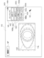
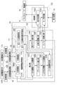
- FIG. 6 is a screen diagram showing an observation screen when the AF mode is set in the present embodiment. It is a functional block diagram which shows the function of the surgical microscope when AF mode is set in this embodiment. It is a schematic image figure which shows the image obtained by performing a two-dimensional discrete Fourier transform with respect to the right image in this embodiment. It is a schematic image figure which shows the image obtained by performing a two-dimensional discrete Fourier transform with respect to the left image in this embodiment. It is an aspect figure which shows the aspect which displayed the phase-only correlation function in this Embodiment in three-dimensional form.
- FIG. 6 is an explanatory diagram for explaining a shift amount from a current focus position to a focus surface in the present embodiment. It is explanatory drawing with which the shift amount of the right side operative field image and left side operative field image and the shift amount of a right side image and a left side image in this embodiment are demonstrated. It is a screen figure which shows the state in which the focus position designation guide information was displayed in the observation screen in this embodiment.
- FIG. 7 is a screen view showing a mode in which the sample surgical field image displayed in the observation screen in this embodiment is divided into a plurality of regions.
- FIG. 6 is a schematic image diagram showing an alpha blended image when the outer edge of the iris is in focus in the present embodiment.
- FIG. 7 is a schematic image diagram showing an alpha blend image when the outer edge of the pupil is in focus in the present embodiment.
- FIG. 7 is a screen view showing a state in which a split image and upward movement required amount information are displayed in the observation screen in the present embodiment.
- FIG. 6 is a screen view showing a state in which a right side image, a left side image, a right side contrast value indicator, and a left side contrast value indicator are displayed in live view on the observation screen in the present embodiment. It is a schematic image figure which shows the right side image and the right side contrast value indicator which penetrated the lens for right eyes in this embodiment. It is a schematic image figure which shows the left side image and left side contrast value indicator which penetrated the lens for left eyes in this embodiment.
- FIG. 6 is a screen view showing a state in which a right side image, a left side image, and a contrast value indicator are live-view displayed in the observation screen in the present embodiment.
- FIG. 6 is a screen view showing an observation screen including a contrast confirmation screen on which a right side image and a right side contrast value indicator are displayed and a stereoscopic image display screen according to the present embodiment.
- FIG. 6 is a screen view showing an observation screen including a contrast confirmation screen on which a left image and a left contrast value indicator are displayed and a stereoscopic image display screen according to the present embodiment.
- FIG. 6 is a screen view showing an observation screen including a right-side image, a right-side contrast value indicator, a left-side image, and a contrast confirmation screen on which a left-side contrast value indicator is displayed and a stereoscopic image display screen according to the present embodiment.
- FIG. 6 is a screen view showing an observation screen including a right-side image, a right-side contrast value indicator, a left-side image, and a contrast confirmation screen on which a left-side contrast value indicator is displayed and a stereoscopic image display screen according to the present embodiment.
- FIG. 6 is a screen view showing a state in which a right side image, a right side contrast value graph, a left side image, and a left side contrast value graph in the present embodiment are displayed in live view.
- FIG. 5 is a schematic image diagram showing a right-side image and a right-side contrast value graph that are transmitted through the right-eye lens in the present embodiment.
- FIG. 6 is a schematic image diagram showing a left-side image and a left-side contrast value graph that have passed through the left-eye lens in the present embodiment.
- FIG. 7 is a screen view showing a state in which a right-side image, a left-side image, and a contrast value graph in the present embodiment are displayed in live view.
- FIG. 5 is a schematic image diagram showing a right-side image and a right-side contrast value graph that are transmitted through the right-eye lens in the present embodiment.
- FIG. 6 is a schematic image diagram showing a left-side image and a left-side contrast value graph that have passed through the left
- FIG. 6 is a screen diagram showing a contrast change confirmation screen on which a right-side image and a right-side contrast value graph are displayed and a stereoscopic image display screen as an observation screen.
- FIG. 5 is a screen view showing a viewing screen for a contrast change confirmation screen on which a left-side image and a left-side contrast value graph are displayed and a stereoscopic image display screen in the present embodiment.
- FIG. 6 is a screen diagram showing a viewing screen for a stereoscopic image display screen and a contrast change confirmation screen on which a right side image, a right side contrast value graph, a left side image, and a left side contrast value graph are displayed in the present embodiment.
- FIG. 5 is a screen view showing a viewing screen for a contrast change confirmation screen on which a left-side image and a left-side contrast value graph are displayed and a stereoscopic image display screen in the present embodiment.
- FIG. 6 is a screen diagram showing a viewing screen for a stereoscopic image display
- FIG. 9 is a screen view showing a state in which a contrast value on the right contrast value graph is designated by an arrow pointer on the observation screen in the present embodiment.
- FIG. 7 is a screen view showing a state in which the first to sixth focus support information and the live view images of the right side image and the left side image are displayed in the observation screen in the present embodiment.
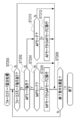
- It is a flow chart which shows a flow of focus mode setting processing in this embodiment.
- It is a flow chart which shows a flow of peak coordinate specific processing in this embodiment.
- FIG. 9 is a screen diagram in a state where an AF mode is set on the observation screen according to the second embodiment. It is a screen figure in the state where MF mode was set up in the screen for observation concerning a 2nd embodiment.
- FIG. 6 is an explanatory diagram for explaining a shift amount from a current focus position to a focus surface in the present embodiment.
- the CPU means the abbreviation of "Central Processing Unit”.
- the RAM is an abbreviation of “Random Access Memory”.
- the ROM is an abbreviation for “Read Only Memory”.
- ASIC is an abbreviation for “Application Specific Integrated Circuit”.
- PLD is an abbreviation for "Programmable Logic Device”.
- FPGA is an abbreviation of “Field-Programmable Gate Array”.
- SSD refers to the abbreviation of “Solid State Drive”.
- DVD-ROM is an abbreviation of “Digital Versatile Disc Read Only Memory”.
- USB is an abbreviation for “Universal Serial Bus”.
- the HDD is an abbreviation for “Hard Disk Drive”.
- the EEPROM is an abbreviation of “Electrically Erasable and Programmable Read Only Memory”.
- the DRAM is an abbreviation of “Dynamic Random Access Memory”.
- SRAM refers to an abbreviation of “Static Random Access Memory”.
- the LSI is an abbreviation of “Large-Scale Integration”.
- CCD is an abbreviation for “Charge Coupled Device”.
- CMOS refers to an abbreviation of “Complementary Metal Oxide Semiconductor”.
- AF is an abbreviation for “Auto Focus”.
- MF is an abbreviation for “Manual Focus”.
- horizontal used in the following description includes not only perfect horizontal but also substantially horizontal meaning that includes an allowable error in design and manufacturing.
- vertical used in the following description includes not only complete verticality but also substantially vertical meaning that includes an allowable error in design and manufacturing.
- right angle includes an angle obtained by intersecting a horizontal line and a vertical line. Further, the term “right angle” used herein includes not only a perfect “right angle” but also a substantially right angle including an allowable error in design and manufacturing.
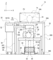
- FIG. 1 shows a surgery support system 10.
- the surgery support system 10 is an example of a microscope system according to the technique of the present disclosure.
- the surgery support system 10 includes a surgical microscope 12 and a display 14.
- the surgical microscope 12 is an example of a microscope according to the technique of the present disclosure
- the display 14 is an example of a display unit according to the technique of the present disclosure.
- the surgical microscope 12 includes a surgical microscope main body 16, an adjusting device 18, and a reception device 19.
- the adjusting device 18 is an example of an adjusting unit and a microscope adjusting device according to the technique of the present disclosure.
- the operating microscope 12 includes an ophthalmic microscope applied to the operation or observation of the eye 20A of the patient 20, or a surgical microscope applied to the operation or observation of the affected part of the patient 20.
- a patient 20 to be observed by the operating microscope 12 is placed on an operating table 22 in an operable posture.
- the operable posture refers to, for example, a state of lying on the back.
- the user 24 of the surgery support system 10 mounts the patient 20 and the surgical microscope main body 16 from the top of the patient 20 with respect to the patient 20 and the surgical microscope main body 16 placed on the operating table 22 in an operable posture. They are facing each other in a downright position.
- the user 24 refers to, for example, a surgeon, but the technique of the present disclosure is not limited to this.
- the user 24 may be an assistant who assists the work of the surgeon from the side or the back of the surgeon.
- the surgical microscope body 16 includes an objective lens 26.
- the optical axis direction of the objective lens 26 coincides with the vertical direction.
- the term “match” as used herein also includes an approximate match in the sense of including an allowable error in design and manufacturing.
- the objective lens 26 has an objective surface 26A facing the outside of the surgical microscope body 16.
- the objective surface 26A includes the lens surface of the objective lens 26 that is closest to the surgical field 28 side. Further, the objective surface 26A is an incident surface on which the observation light reflected by a predetermined part of the patient 20 is incident, and is also a lens surface on which the reflected light from the operative field 28 is incident.
- the adjusting device 18 includes an adjusting device main body 30, a control device 32, a support base 34, casters 36, and a support arm 38.
- the support base 34 is formed in a columnar shape, and a plurality of casters 36 are provided at the lower end of the support base 34.
- the adjustment device main body 30 is supported on the support base 34 so as to be slidable along the Z direction.
- the “Z direction” mentioned here refers to the vertical direction.
- the "X direction” refers to the horizontal direction
- the "Y direction” refers to the direction that is perpendicular to the two directions of the X direction and the Z direction.
- the adjustment device body 30 includes a rectangular parallelepiped housing 30A.
- a control device 32 is housed in the housing 30A.
- the control device 32 is a device that integrally controls the surgery support system 10.
- a columnar support arm 38 is attached to the side surface of the housing 30A. It projects from the side surface of the housing 30A along the horizontal direction. One end of the support arm 38 is fixed to the adjustment device body 30. The other end of the support arm 38 is fixed to the side surface of the housing 16A of the surgical microscope body 16. As a result, the surgical microscope main body 16 is supported by the adjusting device main body 30 from the side of the surgical microscope main body 16 via the support arm 38.
- the surgical microscope body 16 is arranged so that the objective surface 26A is located in front of the operative field 28 and below the line of sight of the user 24 located on the parietal side of the patient 20. That is, the line of sight of the user 24 is in a region in the positive direction of the Z axis with respect to the surgical microscope body 16 supported by the support arm 38.
- the surgical microscope body 16 arranged in this manner takes in the operative field light (observation light) that is the reflected light for the operative field 28 from the objective lens 26, and the operative field image (observation image, left side) based on the captured operative field light. Image and the right image).
- the operative field 28 an area including the eye 20A to be operated and the peripheral part of the eye 20A is illustrated, but the operative field 28 is not limited to this, and the operative field 28 is, for example, only the eye 20A. It may be present, or may be only a region recognized by the user 24 as a lesion in the eye 20A.
- the surgical field 28 may be a region that the user 24 has set as an observation target.
- the display 14 may be a liquid crystal display or an organic EL display.
- the display 14 is installed on the upper surface of the caster table 39 having a gate shape in a front view when viewed from the user 24 side.
- the caster table 39 includes a top plate 39A and legs 39B and 39C. Casters 39D are provided on the bottom surface of the leg portion 39B, and casters 39E are provided on the bottom surface of the leg portion 39C.
- the top plate 39A is formed along a horizontal plane.
- the top plate 39A is supported by the leg portion 39B from one end side and is supported by the leg portion 39C from the other end side. Therefore, the shape of the outline of the caster table 39 is a front view gate shape as viewed from the user 24 side by the top plate 39A and the legs 39B and 39C.
- the caster table 39 is arranged at the user front position P.
- the user front position P refers to a position which is located in front of the user 24 and which straddles the operating table 22 and the patient 20 placed on the operating table 22 in an operable posture.
- the abdomen of the patient 20 is located just below the top plate 39A
- the leg 39B is located on one side of the abdomen of the patient 20
- the leg 39C is located on the other side of the abdomen of the patient 20. It is arranged to be located.
- the surgical microscope 12 is arranged at a position outside the visual field region FV for the surgical field image while the user 24 is viewing the screen 14A from the front side of the surgical microscope main body 16.
- the visual field region FV refers to a spatial region of the screen of the user 24 in the state in which the user 24 is looking at the screen 14A from the front side of the surgical microscope main body 16 and is targeted for the screen 14A.
- the visual field region FV is determined based on the positional relationship between the pupil of the user 24 and the screen 14A.
- the reception device 19 includes a touch pad 40, a left click button 42, a right click button 44, an upward movement foot switch 46, and a downward movement foot switch 48.
- the touch pad 40, the left click button 42, and the right click button 44 are provided on the plate 50.
- the plate 50 is leaned against the floor surface F by a supporting member (not shown).
- the touch pad 40 is arranged at the center of the plate 50.
- the touch pad 40 receives an instruction from the user 24, for example, by detecting a position where the toes of the foot of the user 24 are in contact.
- a left click button 42 and a right click button 44 are arranged below the touch pad 40 in the plate 50.
- the left-click button 42 has the same function as the left-click button mounted on a general mouse.
- the right-click button 44 has the same function as the right-click button mounted on a general mouse.
- the left click button 42 and the right click button 44 are operated, for example, by the toes of the foot of the user 24.
- the upward movement foot switch 46 is a pedal type switch, and is depressed by the foot of the user 24 when moving the surgical microscope body 16 upward, that is, in the positive direction of the Z axis.
- the downward movement foot switch 48 is a pedal type switch, and is depressed by the foot of the user 24 when the surgical microscope main body 16 is moved downward, that is, in the negative direction of the Z axis.
- foot switches without reference numerals.
- the above-mentioned surgical field light is roughly classified into a right surgical field light showing the surgical field 28 and a left surgical field light showing the surgical field 28.
- the right operative field light is an example of the right observing target light according to the technique of the present disclosure
- the left operative field light is an example of the left observing target light according to the technique of the present disclosure.
- the “right side” refers to the right side when the surgical microscope main body 16 is viewed from the user 24, in other words, the positive direction of the X axis.
- the “left side” refers to the left side when the surgical microscope main body 16 is viewed from the user 24, in other words, the negative direction of the X axis.
- an operative field image showing the operative field 28 is generated as a parallax image by the right operative field light (right observing target light) and the left operative field light (left observing target light).
- the parallax image is a pair of images having parallax.
- the right operative field light is the operative field light for generating one of the pair of images having parallax
- the left operative field light is the other image of the pair of images having parallax. It is a light for surgery.
- One of the pair of images having parallax is an image for one eye of the user 24.
- the “image for one eye of the user 24” mentioned here is an example of a right image, and for example, refers to an image for the right eye which is an image for the right eye of the user 24.
- the other image of the pair of images having parallax is the image for the other eye of the user 24.
- the "image for the other eye of the user 24" here is an example of a left-side image, and indicates, for example, an image for the left eye that is an image for the left eye of the user 24.
- the parallax image is roughly divided into the right parallax image (in this case, the right image) and the left parallax image (in this case, the left image).
- the right parallax image is an image generated based on the right surgical field light
- the left parallax image is an image generated based on the left surgical field light. Since the right-side parallax image and the left-side parallax image are images having parallax, in the surgical microscope 12, the right-side parallax image and the left-side parallax image are displayed on the display 14 by the stereoscopic method, so that the surgical field image is displayed by the user 24. Is visually perceived as a stereoscopic image (parallax image).
- the “stereoscopic method” mentioned here includes, for example, a naked-eye method, a head-mounted display method, and an eyeglass method.
- Examples of the naked-eye method include a parallax barrier method and a lenticular lens method.
- the user 24 wears the head-mounted display. Then, the right parallax image displayed on the right eye display of the head mounted display is visually recognized by the right eye of the user 24, and the left parallax image displayed on the left eye display of the head mounted display is visually recognized by the left eye of the user 24.
- the surgery support system 10 of the present embodiment employs a polarization method.
- the user 24 wears the polarized glasses 52 to visually recognize the display 14. That is, in the polarization method, the operative field image is stereoscopically viewed by allowing the user 24 to visually recognize the right-eye parallax image and the left-eye parallax image displayed on the display 14.
- the right-side parallax image and the left-side parallax image are displayed on the display 14 in a state of being overlapped with each other with linearly polarized light orthogonal to each other.
- linearly polarized light is illustrated here, it is not limited to this and circularly polarized light may be used.
- the polarized glasses 52 include a right-eye lens 52R and a left-eye lens 52L, and the left-eye parallax image and the right-eye parallax image are formed by the right-eye lens 52R and the left-eye lens 52L. And separate.
- the front side of the right eye of the user 24 is covered with the lens 52R for the right eye
- the front side of the left eye of the user 24 is covered with the lens 52L for the left eye.
- a polarizing filter (not shown) for the right eye is attached to the right eye lens 52R
- the right eye lens 52R includes the right parallax image light 54R of the right parallax image light 54R and the left parallax image light 54L.
- the normal image light 58 is also transmitted.
- a polarizing filter (not shown) for the left eye is attached to the lens 52L for the left eye, which transmits the left parallax image light 54L of the right parallax image light 54R and the left parallax image light 54L, and The image light 58 is also transmitted.
- the right-side parallax image light 54R is an example of the right-side observation target light, and refers to the light indicating the right-side parallax image displayed on the display 14.
- the left-side parallax image light 54L is an example of left-side observation target light, and refers to light indicating the left-side parallax image displayed on the display 14.
- the normal image light 58 refers to visible light that is not polarized. That is, the visible light also includes visible light indicating an image other than the right parallax image and the left parallax image among the images displayed on the display 14.
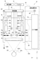
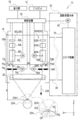
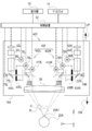
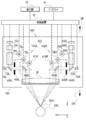
- the surgical microscope main body 16 includes an optical system 60.
- the optical system 60 includes an objective lens 26, a right side illumination optical system 60R, and a left side illumination optical system 60L.
- the optical system 60 is a Galileo type observation optical system. Therefore, in the optical system 60, the objective lens 26 is shared by the right side illumination optical system 60R and the left side illumination optical system 60L.
- the Galileo-type observation optical system is illustrated, but the technique of the present disclosure is not limited to this, and for example, a Greenough-type observation optical system or a pupil division-type observation optical system is used. Is also possible.
- the right side illumination optical system 60R includes a right side imaging element 62R, a right side imaging optical system 64R, a right side magnification optical system 66R, a right side deflection element 68R, a right side light source 70R, a right side illumination optical system 72R, and a right side diaphragm 74R.
- the right diaphragm 74R is a movable diaphragm, and is mechanically connected to the drive shaft of the right diaphragm driving motor 78R.
- the right diaphragm drive motor 78R is electrically connected to the control device 32 and operates under the control of the control device 32.
- the right diaphragm 74R is opened and closed by the power of the right diaphragm driving motor 78R being applied in accordance with the instruction from the control device 32. That is, the opening degree of the right-side throttle 74R is controlled by the control device 32.
- the right magnification varying optical system 66R includes a plurality of lenses including at least one magnification varying lens, and the magnification varying lens is mechanically connected to the drive shaft of the right magnification varying motor 76R. There is.
- the right scaling motor 76R is electrically connected to the control device 32 and operates under the control of the control device 32.
- the variable power lens of the right variable power optical system 66R moves along the optical axis direction of the right variable power optical system 66R when the power of the right variable power motor 76R is applied according to an instruction from the control device 32. That is, the position of the variable power lens of the right variable power optical system 66R is controlled by the controller 32.
- Right side light source 70R emits right side illumination light, which is light for right side observation, toward right side illumination optical system 72R.
- the right side illumination optical system 72R is an optical system including at least one lens, and transmits the right side illumination light emitted as the illumination light from the right side light source 70R and guides it to the right side deflection element 68R.
- the right deflection element 68R reflects the right illumination light guided by the right illumination optical system 72R toward the right movable diaphragm 74R.
- the right-side deflection element 68R may be, for example, a transflective element that transmits the right-side illumination light and reflects the right-side operative field light.
- the transflective element include a half mirror, a beam splitter, and a dichroic mirror.
- the right illumination light passes through the right diaphragm 74R, is refracted by the objective lens 26, and enters the eye portion 20A.
- the right side illumination light is obliquely incident on the cornea 20A1 of the eye portion 20A from the positive side of the X axis to the negative side of the X axis.
- the light obtained by the right side illumination light being reflected by the eye portion 20A is incident on the right side deflecting element 68R as the above-mentioned right side surgical field light by tracing back the optical path coaxial with the right side illumination light.
- Lights of a plurality of wavelengths including right surgical field light are incident on the right deflection element 68R.
- the right-side deflection element 68R transmits the right-side surgical field light of the plurality of incident wavelength light beams to deflect the right-side surgical field light to the right-side variable magnification optical system 66R.
- Right-side surgical field light deflected by the right-side deflecting element 68R is incident on the right-side variable magnification optical system 66R.
- the right variable power optical system 66R changes the right surgical field image shown by the incident right surgical field light.
- the right-side variable power optical system 66R transmits the incident right-side surgical field light and guides it to the right-side imaging optical system 62R.
- the right imaging optical system 64R is an optical system including at least one lens, takes in the right surgical field light guided by the right zoom optical system 66R, and receives the captured right surgical field light of the right imaging element 62R. Form an image on the surface.
- a CMOS image sensor is used as the right image pickup element 62R.
- the right image pickup device 62R is an image pickup device in which a photoelectric conversion element, a signal processing circuit (for example, LSI), and a memory (for example, DRAM or SRAM) are integrated into one chip.
- a laminated image sensor can be cited.
- a signal processing circuit and a memory are laminated on a photoelectric conversion element.
- the right image pickup device 62R is not limited to the CMOS image sensor, but may be a CCD image sensor, for example.
- the right imaging element 62R images the operative field 28 (see FIG. 1) at a specific frame rate (for example, 60 fps (frames per second)) based on the right operative field light imaged on the light receiving surface.
- a specific frame rate for example, 60 fps (frames per second)
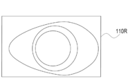
- the right image 110R showing the operative field 28 is generated by the right image sensor 62R, and the generated right image 110R is output to the control device 32 as a moving image by the right image sensor 62R.
- the left side illumination optical system 60L includes a left side imaging element 62L, a left side imaging optical system 64L, a left side variable magnification optical system 66L, a left side deflection element 68L, a left side light source 70L, a left side illumination optical system 72L, and a left side diaphragm 74L.
- the left diaphragm 74L is a movable diaphragm, and is mechanically connected to the drive shaft of the left diaphragm driving motor 78L.
- the left diaphragm drive motor 78L is electrically connected to the control device 32 and operates under the control of the control device 32.
- the left diaphragm 74L opens and closes when the power of the left diaphragm driving motor 78L is applied according to an instruction from the control device 32. That is, the opening degree of the left throttle 74L is controlled by the control device 32.
- the left-side variable power optical system 66L includes a plurality of lenses including at least one variable-power lens, and the variable-power lens is mechanically connected to the drive shaft of the left-side variable-power motor 76L. There is.
- the left scaling motor 76L is electrically connected to the control device 32 and operates under the control of the control device 32.
- the variable power lens of the left variable power optical system 66L moves along the optical axis direction of the left variable power optical system 66L when the power of the left variable power motor 76L is applied according to the instruction of the control device 32. That is, the position of the variable power lens of the left variable power optical system 66L is controlled by the controller 32.
- the left-side light source 70L emits left-side illumination light, which is light for left-side observation, toward the left-side illumination optical system 72L.
- the left side illumination optical system 72L is an optical system including at least one lens, and transmits the left side illumination light emitted as the illumination light from the left side light source 70L and guides it to the left side deflection element 68L.
- the left deflection element 68L reflects the left illumination light guided by the left illumination optical system 72L toward the left movable diaphragm 74L.
- the left-side deflecting element 68L may be, for example, a transflective element that transmits the left-side illumination light and reflects the left-side surgical field light.
- the transflective element include a half mirror, a beam splitter, and a dichroic mirror.
- the left illumination light passes through the left diaphragm 74L, is refracted by the objective lens 26, and enters the eye 20A.
- the left side illumination light is obliquely incident on the cornea 20A1 of the eye portion 20A from the negative side of the X axis to the positive side of the X axis.
- the light obtained by the left side illumination light being reflected by the eye portion 20A goes back to the left side deflection element 68R as the above-mentioned left side operative field light by tracing back the optical path coaxial with the observation light.
- a plurality of wavelengths of light including the left operative field light is incident on the left deflection element 68L.
- the left-side deflecting element 68L transmits the left-side surgical field light of the plurality of incident wavelength lights to deflect the left-side surgical field light to the left-side variable power optical system 66L.
- the left operative field light deflected by the left deflecting element 68L is incident on the left variable power optical system 66L.
- the left zoom optical system 66L zooms the left surgical field image indicated by the incident left surgical field light.
- the left zoom optical system 66L transmits the incident left surgical field light and guides it to the left imaging optical system 64L.
- the left imaging optical system 64L is an optical system including at least one lens, takes in the left surgical field light guided by the left zoom optical system 66L, and receives the captured left surgical field light of the left imaging element 62L. Form an image on the surface.
- the left image pickup device 62L is an image pickup device having the same structure as the right image pickup device 62R.
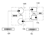
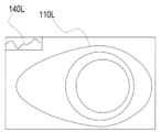
- the left imaging element 62L images the surgical field 28 (see FIG. 1) at the same frame rate as the right imaging element 62R based on the left surgical field light imaged on the light receiving surface. Accordingly, the left image 110L (see FIG. 7) showing the operative field 28 is generated by the left image sensor 62L, and the generated left image 110L is output to the control device 32 as a moving image by the left image sensor 62L.
- the adjusting device main body 30 includes a slide mechanism 78 in the housing 30A.
- One end of the support arm 38 is fixed to the slide mechanism 78.
- the slide mechanism 78 is mechanically connected to the drive shaft of the focus position adjusting motor 80.
- the focus position adjusting motor 80 is electrically connected to the control device 32 and is controlled by the control device 32.
- Examples of the slide mechanism 78 include a rack and pinion, a crank mechanism, and/or a ball screw mechanism.
- the slide mechanism 78 moves the surgical microscope main body 16 along the vertical direction via the support arm 38 when the power of the focusing position adjusting motor 80 is applied according to the instruction of the control device 32. That is, the slide mechanism 78 receives the power from the focusing position adjusting motor 80 under the control of the control device 32, and selects the entire optical system 60 together with the housing 16A in the vertically upward direction UP and the vertically downward direction DW. Move it.
- the focus position GP on the object point side of the optical system 60 (hereinafter, simply referred to as “focus position GP”) is located closer to the objective lens 26 than the cornea 20A1.
- the control device 32 operates the slide mechanism 78 to move the surgical microscope body 16 in a predetermined moving direction (for example, the vertical downward direction DW, one direction, and a linear direction), and thereby the focus position GP. Can be fitted to the cornea 20A1.
- the focus position is adjusted by moving the surgical microscope body 16, but the technique of the present disclosure is not limited to this.
- a focus lens may be incorporated in the optical system 60, and the focus position may be adjusted by moving the focus lens.
- the in-focus position GP refers to the position where the focus is achieved.
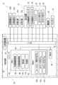
- FIG. 5 is a block diagram showing the configuration of the electric system of the surgery support system 10.
- the control device 32 includes a computer 82 and a secondary storage device 83.
- the computer 82 includes a CPU 84, a ROM 86, a RAM 88, and an I/O (input/output interface) 90.
- the CPU 84, ROM 86, and RAM 88 are connected to the bus line 92.
- the bus line 92 is connected to the I/O 90.
- the secondary storage device 83 is also connected to the I/O 90.
- the CPU 84 exchanges information with the ROM 86, the RAM 88, and the secondary storage device 83.
- the CPU 90 centrally controls the entire surgery support system 10.
- the ROM 86 is a memory that stores a program for controlling the basic operation of the surgery support system 10, various parameters, and the like.
- the RAM 88 is a volatile memory used as a work area or the like when executing various programs.
- the secondary storage device 83 is a non-volatile memory that stores a program different from the program stored in the ROM 86 and/or various parameters different from the various parameters stored in the various parameter ROM 86. Examples of the secondary storage device 83 include a HDD, an EEPROM, and/or a flash memory.
- a plurality of external devices are connected to the I/O 90.
- the plurality of external devices connected to the I/O 90 are the right image pickup device 62R, the left image pickup device 62L, the right light source 70R, the left light source 70L, the reception device 19, the drive source 94, and the display 14. It is shown.
- the reception device 19 is a device that receives an instruction from the user 24, and includes an upward movement foot switch 46, a downward movement foot switch 48, a touch pad 40, a left click button 42, and a right click button 44. ..
- the drive source 94 is a plurality of drive devices that generate power for moving mechanical parts, and includes a right-side aperture driving motor 78R, a left-side aperture driving motor 78L, a right-side scaling motor 76R, and a left-side scaling motor 76L. , And a focusing position adjusting motor 80 and the like.
- the right side image pickup device 62R, the left side image pickup device 62L, the right side light source 70R, the left side light source 70L, the reception device 19, the drive source 94, and the display 14 are controlled by the CPU 84, respectively.
- ROM86 stores a focus system program.
- the “focus system program” mentioned here refers to the focus mode setting program 104, the AF mode program 106, and the MF mode program 108.
- the CPU 84 reads the focus system program from the ROM 86 and expands the read focus system program in the RAM 88. Then, the CPU 84 operates as the right side image acquisition unit 96, the left side image acquisition unit 98, the derivation unit 100, and the control unit 102 by executing the focus system program expanded in the RAM 88.
- the operating microscope 12 has an AF mode and an MF mode as operation modes for adjusting the focus position.
- the AF mode and the MF mode are selectively set in the surgical microscope 12.
- FIG. 6 shows a mode of the focus adjustment screen 14B displayed on the display 14 when the focus mode setting program 104 is executed by the CPU 84.
- An observation start button 14C, a menu window 14D, and an arrow pointer 14E are displayed on the focus adjustment screen 14B.
- the display modes of the observation start button 14C, the menu window 14D, and the arrow pointer 14E change based on the instruction received by the reception device 19.
- the arrow pointer 14E moves within the focus adjustment screen 14B based on the instruction received by the touchpad 40.
- the observation start button 14C is turned on.
- imaging of the observation target for example, the operative field 28
- the right imaging element 62R and the left imaging element 62L is started.
- the operative field 28 (see FIG. 1) is imaged by the right imaging element 62R, a right image 110R is obtained and generated as shown in FIG.
- the operative field 28 see FIG. 1
- the left imaging element 62L a left image 110L is obtained and generated as shown in FIG.
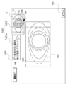
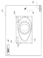
- the screen of the display 14 is switched from the focus adjustment screen 14B to the observation screen 14G under the control of the CPU 84, as shown in FIG.
- the observation screen 14G is different from the focus adjustment screen 14B in that an observation end button 14F is displayed instead of the observation start button 14C and a right side image 110R and a left side image 110L are displayed.
- the observation end button 14F is turned on when the observation of the surgical field 28 is finished.
- the method of turning on the observation end button 14F is the same as the method of turning on the observation start button 14C.
- the right-side image 110R and the left-side image 110L are displayed in a state of being overlapped with each other in an area of the observation screen 14G that does not overlap with the observation end button 14F and the menu window 14D.
- the stereoscopic image 112 based on the right image 110R and the left image 110L is the observation screen 14G. It is perceived by the user 24 at a position protruding from. This is because light showing the right side image 110R passes through the right eye lens 52R of the polarizing glasses 52 as the above right parallax image light 54R, and light showing the left side image 110L as the above left parallax image light 54L of the polarizing glasses 52. This is because the light passes through the left-eye lens 52L (see FIG. 3).
- an AF mode button 14D1 an MF mode button 14D2, an aperture opening change button 14D3, a zoom magnification change button 14D4, a minimize button 14D5, and a maximize button 14D6 are provided. It is displayed.
- the method of turning on the various buttons in the menu window 14D is the same as the method of turning on the observation start button 14C. That is, when the arrow pointer 14E is operated by the user 24, various buttons in the menu window 14D are turned on.
- the AF mode button 14D1 is turned on when the operation mode of the surgical microscope 12 is set to the AF mode
- the MF mode button 14D2 is turned on when the operation mode of the surgical microscope 12 is set to the MF mode.
- the AF mode button 14D1 when the AF mode button 14D1 is turned on, under the control of the CPU 84, the AF mode button 14D1 is highlighted and the MF mode button 14D2 is highlighted as shown in FIG.
- the aperture opening change button 14D3 is a button operated when changing the opening of both the right aperture 74R and the left aperture 74L (hereinafter, simply referred to as "aperture aperture”).
- the aperture opening change button 14D3 has an opening “small” button 14D3a, an opening “large” button 14D3b, and an opening display column 14D3c.
- the opening degree display field 14D3c a numerical value indicating the current throttle opening degree is displayed under the control of the CPU 84.
- the opening "small” button 14D3a is turned on, the aperture opening is reduced under the control of the CPU 84, and when the opening "large” button 14D3b is turned on, the aperture opening is increased under the control of the CPU 84.
- the numerical value of the aperture display field 14D3c is updated according to the change of the aperture opening under the control of the CPU 84.
- the zoom magnification change button 14D4 is a button operated when changing the zoom magnification (hereinafter, simply referred to as “zoom magnification”) by both the right variable magnification optical system 66R and the left variable magnification optical system 66L.
- the zoom magnification change button 14D4 has a zoom magnification “small” button 14D4a, a zoom magnification “large” button 14D4b, and a zoom magnification display field 14D4c. Under the control of the CPU 84, a numerical value indicating the current zoom magnification is displayed in the zoom magnification display field 14D3c.
- the zoom magnification “small” button 14D4a When the zoom magnification “small” button 14D4a is turned on, the zoom magnification is reduced under the control of the CPU 84, and when the zoom magnification “large” button 14D4b is turned on, the zoom magnification is increased under the control of the CPU 84.
- the zoom magnification is changed in this way, the value of the zoom magnification display field 14D4c is updated according to the change of the zoom magnification under the control of the CPU 84.
- the minimize button 14D5 is a button operated when the menu window 14D is minimized.
- the maximize button 14D6 is a button operated when maximizing the menu window 14D. In the example shown in FIG. 8, the menu window 14D is maximized.
- the maximize button 14D6 is turned on while the menu window 14D is maximized, the size of the menu window 14D can be changed using the arrow pointer 14E.
- FIG. 11 is a functional block diagram showing the functions of the surgical microscope 12 when the operation mode of the surgical microscope 12 is the AF mode.
- the right-side image acquisition unit 96 acquires from the right-side image sensor 62R a right-side image 110R obtained by capturing the operative field 28 (see FIG. 1) with the right-side image sensor 62R. Then, the right image acquisition unit 96 stores the right image 110R acquired from the right image sensor 62R in the captured image storage area 88A of the RAM 88.
- the left-side image acquisition unit 98 acquires the left-side image 110L obtained by capturing the operative field 28 (see FIG. 1) by the left-side image sensor 62L from the left-side image sensor 62L. Then, the left-side image acquisition unit 98 stores the left-side image 110L acquired from the left-side image sensor 62L in the captured-image storage area 88A of the RAM 88.
- the deriving unit 100 derives the correlation between the right-side image 110R and the left-side image 110L by the phase-only correlation method at a predetermined timing (for example, AF mode).
- the derivation unit 100 includes a two-dimensional discrete Fourier transform unit 100A, a power spectrum calculation unit 100B, a two-dimensional inverse discrete Fourier transform unit 100C, a peak coordinate identification unit 100D, a displacement vector calculation unit 100E, a focus position calculation unit 100F, and a contrast value. It has a calculation unit 100G.
- the two-dimensional discrete Fourier transform unit 100A performs a discrete Fourier transform on the right image 110R according to the following mathematical expression (1). Also, the two-dimensional discrete Fourier transform unit 100A performs a discrete Fourier transform on the left image 110L according to the following mathematical expression (2).
- the image 110FR is obtained by the function F(k 1 , k 2 ) as illustrated in FIG. 12A.
- the image 110FL is obtained by the function G(k 1 , k 2 ) as illustrated in FIG. 12B.
- f(n 1 , n 2 ) is a function indicating the right image 110R of N 1 ⁇ N 2 pixels
- g(n 1 , n 2 ) is N 1 It is a function showing the left image 110L of ⁇ N 2 pixels.
- M 1 and M 2 are positive integers
- a F (k 1 , k 2 ) and A G (k 1 , k 2 ) are amplitude spectra
- K 1 , k 2 ) is an amplitude spectrum.
- ⁇ n1, n2 included in the equations (1) and (2) are defined as follows.
- the power spectrum calculation unit 100B calculates the normalized mutual power spectrum R(k 1 , k 2 ) using the following mathematical expression (3) based on the conversion result of the two-dimensional discrete Fourier transform unit 100A.
- the two-dimensional inverse discrete Fourier transform unit 100C calculates the phase-only correlation function r(n 1 , n 2 ) as the two-dimensional inverse Fourier transform of the normalized mutual power spectrum by using the following mathematical expression (4).
- ⁇ k1, k2 included in the mathematical expression (4) is defined as follows.
- the phase-only correlation function r(n 1 , n 2 ) has an extremely sharp peak (correlation peak) rp close to a delta function as shown in FIG.
- the height of the correlation peak rp represents the linearity of the phase difference spectrum of the right-side image 110R and the left-side image 110L. If the phase difference spectrum is linear with respect to the frequency, the height of the correlation peak is 1.
- the height of the correlation peak is useful as a measure of the similarity between the right image 110R and the left image 110L.
- the coordinates of the correlation peak correspond to the relative positional deviation between the right side image 110R and the left side image 110L.
- Two-dimensional discrete Fourier transform is performed on the two images, the normalized mutual power spectrum is calculated based on the result of the two-dimensional discrete Fourier transform, and the normalized mutual power spectrum is two-dimensional inverse Fourier transformed to obtain the phase.
- the limited correlation function is calculated.
- a detailed calculation method for performing a two-dimensional inverse Fourier transform on the calculated normalized mutual power spectrum is disclosed in "http://www.aoki.ecei.tokyo.ac.jp/ ⁇ ito/vol_030.pdf" and the like. Has been done.
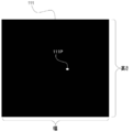
- FIG. 14 shows an inverse Fourier transform image 111, which is a two-dimensional image represented by the phase-only correlation function r(n1, n2) calculated by the two-dimensional inverse discrete Fourier transform unit 100C. That is, the inverse Fourier transform image 111 is an inverse Fourier transform image of the normalized mutual power spectrum.
- the correlation peak 111P appears at the position corresponding to the position of the correlation peak rp shown in FIG.
- the inverse Fourier transform image 111 is stored in the inverse Fourier transform image storage area 88B of the RAM 88 by the two-dimensional inverse discrete Fourier transform unit 100C.
- the peak coordinate specifying unit 100D specifies the coordinates of the correlation peak 111P (hereinafter, referred to as "peak coordinates") from the inverse Fourier transform image 111.
- the peak coordinates are coordinates indicating the position of the maximum pixel value in the inverse Fourier transform image 111. Therefore, as shown in FIG. 15, the peak coordinate specifying unit 100D extends from the origin (X 0 , Y 0 ) to the end point coordinates (X n , Y n ) along the direction of the broken line arrow in the inverse Fourier transform image 111.
- the pixel value for each pixel is acquired, and the coordinates indicating the position of the maximum pixel value are specified. In the example illustrated in FIG.
- the peak coordinate specifying unit 100D acquires pixel values pixel by pixel from the uppermost row to the lowermost row of the inverse Fourier transform image 111, updating the maximum pixel value and updating the maximum pixel value.
- the peak coordinates are specified by updating the coordinates indicating the position of the pixel value of.
- the displacement vector calculation unit 100E calculates the displacement vector based on the peak coordinates identified by the peak coordinate identification unit 100D.
- the “displacement vector” referred to here includes the displacement vector of one of the right image 110R and the left image 110L with respect to the other.
- the displacement vector calculation unit 110E calculates the displacement vector of the left image 110L with respect to the right image 110R.
- the displacement vector (d x , d y ) is the movement amount of Equation (2) with respect to f(n 1 , n 2 ) shown in Equation (1).
- ⁇ 1 refers to "(width-1)/2”
- ⁇ 2 refers to "(height-1)/2”.
- Width is the "width” shown in FIG. 15, and "height” is the “height” shown in FIG.
- the focus position calculation unit 100F calculates an adjustment amount dz required to adjust the focus position GP to a predetermined position by using the following mathematical expression (5) based on the displacement vector calculated by the displacement vector calculation unit 100E.
- the “predetermined position” mentioned here refers to an observation position (for example, the position of the apex of the cornea 20A1) described later.
- the “adjustment amount” referred to here is the shift from the observing position (for example, the current position that is out of focus (the position in the out-of-focus state)) to the focusing surface GG shown in FIG. It corresponds to the amount and includes the movement direction and movement amount of the surgical microscope body 16.
- the in-focus surface GG means a surface in focus.
- the focusing surface GG can also be called a “target surface” from the viewpoint of being a surface for autofocusing.
- the observation position is on the cornea 20A1 and the focusing surface GG is formed in the pupil of the eye 20A.
- the focusing surface GG is a focusing surface (target surface) that has the deepest depth of field for the entire operative field 28.
- the position of the focusing surface GG that is, the position of the pupil of the eye 20A is specified by performing image analysis of the right-side image 110R and/or the left-side image 110L by the focusing position calculation unit 100F.
- the following formula (5) is a formula having dx g , de, g as the independent variables and the adjustment amount dz as the dependent variable.
- g is the focusing distance from the objective lens 26 to the focusing surface GG
- de is the distance between the right deflection element 68R and the left deflection element 68L.
- dx g is the amount of deviation in the parallax generation direction on the focusing surface GG.
- dx p is a shift amount between the right side image 110R generated based on the right side surgical field image 109R and the left side image generated based on the left side surgical field image 109L.
- dx g is defined by the following mathematical expression (6). Equation (6) below has ⁇ ,dx i as the independent variable and dx g as the dependent variable. Further, as shown in the following mathematical expression (6), dx i is defined as the ratio of dx p to w p .
- dx i is a right operative field image 109R that is an observation image formed on the light receiving surface (image surface) of the right imaging element 62R and the light receiving surface (image surface) of the left imaging element 62L.
- ⁇ is a total zoom magnification of the optical system.
- the optical system total zoom magnification is a value calculated based on the zoom magnification set at the present time.
- w p is a width between pixels included in the right image pickup element 62R and the left image pickup element 62L, that is, a pitch between pixels.
- the contrast value calculation unit 100G calculates the contrast value of each of the right side image 110R and the left side image 110L. Further, the contrast value calculation unit 100G calculates an arithmetic mean value of the contrast value of the right image 110R and the contrast value of the left image 110L.
- the contrast value calculated by the contrast value calculation unit 100G is mainly used by the motor control unit 102B as a contrast value used for so-called contrast AF. That is, the focus position adjusting motor 80 is controlled by the motor control unit 102B based on the contrast value calculated by the contrast value calculation unit 100G.
- the control unit 102 has a display control unit 102A and a motor control unit 102B.
- the display control unit 102A selectively displays the focus adjustment screen 14B (see FIG. 6) and the observation screen 14G (see FIG. 8) on the display 14.
- the display control unit 102A controls the display 14 to change the display mode of the focus adjustment screen 14B and the observation screen 14G according to the instruction received by the reception device 19.
- the display control unit 102A When displaying the observation screen 14G on the display 14, the display control unit 102A acquires the right side image 110R and the left side image 110L from the captured image storage area 88A at the display frame rate (for example, 60 fps). The display control unit 102A applies linearly polarized light orthogonal to each other to the acquired right image 110R and left image 110L. Then, the display control unit 102A superimposes the right-side image 110R and the left-side image 110L, which are linearly polarized, on the display 14 according to the display frame rate. As a result, as shown in FIG. 9, the stereoscopic image 112 is visually recognized by the user 24 as a live view image or a real-time image at a position protruding from the observation screen 14G.
- the display control unit 102A When displaying the observation screen 14G on the display 14, the display control unit 102A acquires the right side image 110R and the left side image 110L from the captured image storage area 88A at the
- the adjustment amount dz is output to the motor control unit 102B by the focus position calculation unit 100F at an output timing determined based on the display frame rate.
- the “output timing” mentioned here includes, for example, timing defined by a frame rate that is an even multiple of the display frame rate.
- the motor control unit 102B controls the focus position adjusting motor 80 (see FIG. 4) of the drive source 94 so that the focus position GP is adjusted based on the adjustment amount dz input from the focus position calculation unit 100F. To do. As a result, the slide mechanism 78 receives the power of the focusing position adjusting motor 80, so that the surgical microscope main body 16 is moved vertically downward DW so that the focusing position GP is aligned with the focusing surface GG (see FIG. 16). Move to.
- the motor control unit 102B adjusts the focus position adjustment motor 80 (of the drive source 94) so that the focus position GP is adjusted in real time (immediately). (See FIG. 4). Therefore, the right-side image 110R and the left-side image 110L are generated while making the in-focus position GP follow the in-focus surface GG, and the generated right-side image 110R and the left-side image 110L are overlaid and displayed by the live view method (see FIG. 10). ). Accordingly, the stereoscopic image 112 (see FIG. 9) in the focused state on the focusing surface GG is visually recognized by the user 24 as a live view image or a real-time image.
- the motor control unit 102B controls the right diaphragm driving motor 78R (see FIG. 4) and the left diaphragm driving motor 78L (see FIG. 4) so that the diaphragm opening is changed.
- the right diaphragm driving motor 78R (see FIG. 4) and the left diaphragm driving motor 78L are set so that the diaphragm opening becomes smaller than the current diaphragm opening. Controlled.
- the right diaphragm driving motor 78R and the left diaphragm driving motor 78L are controlled so that the diaphragm opening becomes larger than the current diaphragm opening.
- the motor control unit 102B controls the right scaling motor 76R (see FIG. 4) and the left scaling motor 76L (see FIG. 4) so that the zoom magnification is changed.
- the zoom magnification “small” button 14D4a is turned on
- the right scaling motor 76R and the left scaling motor 76L are controlled so that the zoom magnification becomes smaller than the current zoom magnification.
- the zoom magnification “large” button 14D4b is turned on, the right scaling motor 76R and the left scaling motor 76L are controlled so that the zoom magnification becomes larger than the current zoom magnification.
- the display control unit 102A displays the focus position designation guidance information 14G1.
- the focus position designation guidance information 14G1 is information having a guidance message 14G1a and a sample surgical field image 14G1b.
- the guidance message 14G1a and the sample surgical field image 14G1b are displayed adjacent to each other.
- a message “Please specify if there is an area to be focused on.” and an arrow pointing to the side of the sample surgical field image 14G1b are displayed.
- a still image obtained by processing the right image 110R is displayed as the sample surgical field image 14G1b.
- the sample surgical field image 14G1b is a still image obtained by processing the right image 110R.
- an iris image region 15A showing the iris of the eye 20A
- a pupil peripheral image region 15B showing the peripheral part of the pupil of the eye 20A
- a pupil center image region showing the central part of the pupil of the eye 20A.
- 15C is highlighted in a distinguishable manner.
- the display control unit 102A When generating the sample surgical field image 14G1b, the display control unit 102A first acquires the right image 110R from the captured image storage area 88A. Next, the display control unit 102A performs image analysis on the acquired right image 110R, and specifies the iris image region 15A, the pupil peripheral image region 15B, and the pupil center image region 15C based on the result of the image analysis. Then, the display control unit 102A processes the identified iris image area 15A, pupil peripheral image area 15B, and pupil center image area 15C so as to distinguish the right image 110R from other image areas, and displays the image on the observation screen 14G. indicate.
- the display control unit 102A displays the lattice frame 15 over the sample surgical field image 14G1b as shown in FIG.
- the sample surgical field image 14G1b is displayed in a state of being divided into 15 regions by the lattice frame 15.
- the display control unit 102A contrasts the position specifying information for specifying the position of the specified divided area 17 on the sample surgical field image 14G1b.
- the user 24 In order for the user 24 to specify any one of the plurality of divided areas 17, the user 24 operates the touch pad 40 to indicate an arrow pointer to any one of the plurality of divided areas 17. 14E may be positioned and the left click button 42 may be turned on.
- the position specifying information refers to, for example, a unique identifier individually given to each of the plurality of divided areas 17. In the example shown in FIG. 19, since the sample surgical field image 14G1b is divided into 15, the divided regions 17 are given numbers (identifiers) “001 to 015”. When one of the plurality of divided areas 17 is designated by the arrow pointer 14E, the designated divided area 17 is specified from the number given to the designated divided area 17.
- the display control unit 102A erases the grid frame 15 from the display area of the sample surgical field image 14G1b.
- the contrast value calculation unit 100G acquires the right image 110R and the left image 110L from the captured image storage area 88A in real time (immediately).
- the contrast value calculation unit 100G receives the position specifying information, and specifies the divided area 17 designated by the user 24 from the received position specifying information. Then, the contrast value calculation unit 100G calculates the contrast values of the right side designated image area and the left side designated image area of the acquired right side image 110R and left side image 110L, respectively.
- the “right-side designated image area” here refers to an image area corresponding to the divided area 17 (see FIG. 19) designated by the arrow pointer 14E in the right-side image 110R.
- the “left-side designated image area” refers to an image area corresponding to the divided area 17 (see FIG. 19) designated by the arrow pointer 14E in the left-side image 110L.
- the contrast value calculation unit 100G calculates an average value of the contrast value of the right-side designated image area and the contrast value of the left-side designated image area.
- the contrast value calculation unit 100G outputs the calculated addition average value to the motor control unit 102B.
- the motor control unit 102B executes the contrast AF of the AF process based on the addition average value input from the contrast value calculation unit 100G, so that the real space region corresponding to the designated divided region 17 becomes the focused state. Adjust the focus position so that For example, the motor control unit 102B controls the focus position adjustment motor 80 (or the slide mechanism 78) so that the focus position is adjusted to the position where the arithmetic mean value calculated by the contrast value calculation unit 100G is the maximum. As a result, the position of the surgical microscope main body 16 is adjusted along the vertical direction (Z direction shown in FIGS. 1 to 4 and 16).
- the CPU 84 causes the MF mode for the surgical microscope 12 with respect to the surgical microscope 12. The mode is set.
- the MF mode button 14D2 is highlighted and the AF mode button 14D1 is highlighted as shown in FIG.
- the menu window 14D in the MF mode is different from that in the AF mode in that the menu window 14D further includes a focus support instruction receiving unit 21.
- the focus support instruction receiving unit 21 is a set of soft keys, and receives an instruction to display the focus support information on the observation screen 14G to the display control unit 102A.
- the focus support information is information for supporting the MF (Manual Focus) adjustment work by the user 24, and is roughly classified into first to sixth focus support information described below.
- the focus support information is an example of “indication information” according to the technology of the present disclosure, and the indication information refers to adjustment of the in-focus position by the adjustment device 18 in order to adjust the in-focus position to the designated area of the operative field 28.
- the suggestion information includes information that allows the adjustment state of the focus position to be visually recognized.
- the suggestion information is an adjustment state of the in-focus position (for example, in-focus state in focus, out-of-focus state out of focus, and/or how much the focus shifts in the out-of-focus state. It includes information that visually assists the adjustment of the in-focus position.
- the suggestion information includes information that visually guides the adjustment of the focus position by the user 24.
- the content of the instruction includes, for example, information corresponding to the adjustment amount in the present embodiment.
- the focus assistance instruction receiving unit 21 includes a first focus assistance information button 21A, a second focus assistance information button 21B, a third focus assistance information button 21C, a fourth focus assistance information button 21D, a fifth focus assistance information button 21E, and a fifth focus assistance information button 21E. It has 6 focus support information buttons 21F. Note that, for convenience of description, the first focus support information button 21A, the second focus support information button 21B, the third focus support information button 21C, the fourth focus support information button 21D, the fifth focus support information button 21E, and the fourth focus support information button 21E. When it is not necessary to distinguish and explain the 6 focus support information buttons 21F, they are referred to as "focus support information buttons" without reference numerals.
- the method for turning on the focus support information button is the same as the method for turning on the observation start button 14C.
- the control unit 102 When the operation mode of the surgical microscope 12 is the MF mode, the control unit 102 has a display control unit 102A, a motor control unit 102B, and a focus support information control unit 102C, as shown in FIG.
- the focus support information generation unit 102C acquires the right image 110R from the captured image storage area 88A, and based on the right image 110R, the first focus support information 120 (FIG. 22). Reference) is generated.
- the focus support information generation unit 102C outputs the generated first focus support information 120 to the display control unit 102A.
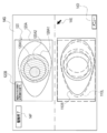
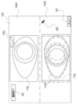
- the display control unit 102A outputs the first focus support information 120 input from the focus support information generation unit 102C to the display 14 to display it in the upper half display area of the observation screen 14G as illustrated in FIG.
- the display control unit 102A displays the right-side image 110R and the left-side image 110L in the live view mode by superimposing the right-side image 110R and the left-side image 110L on the lower half display area of the observation screen 14G.
- the first focus support information 120 is information including a sample surgical field image 120A and a guidance message 120B.
- the sample surgical field image 120A is an image corresponding to an image obtained by enlarging the sample surgical field image 14G1b (see FIG. 18).
- the sample surgical field image 120A is a still image obtained by processing the right image 110R.
- the technique of the present disclosure is not limited thereto, and for example, the still image in which the left image 110L is processed is illustrated. May be used. Alternatively, the still image obtained by processing the right image 110R and the still image obtained by processing the left image 110L may be used together.
- the sample surgical field image 120A is highlighted so that the iris image area 120A1, the pupil periphery image area 120A2, and the pupil center image area 120A3 can be distinguished and recognized.
- the iris image area 120A1 is an image area corresponding to the iris image area 15A shown in FIG.
- the pupil peripheral image area 120A2 is an image area corresponding to the pupil peripheral image area 15B shown in FIG.
- the pupil center image area 120A3 is an image area corresponding to the pupil center image area 15C shown in FIG.
- the guidance message 120B is a message (an example of “indication information” according to the technology of the present disclosure) that indicates to the user 24 that the highlighted region in the sample surgical field image 120A is a candidate for the focused region.
- the message “The highlighted area is a focus area candidate” is displayed in an area that does not overlap the iris image area 120A1, the pupil peripheral image area 120A2, and the pupil center image area 120A3. ing.
- MF adjustment work is performed by operating the reception device 19 (focus operation unit) including the.
- the MF adjustment work includes, for example, operating the foot switch and inputting the MF operation by the user 24.
- the motor control unit 102B controls the focusing position adjusting motor 80 according to the operation of the foot switch by the user 24. That is, the motor control unit 102B moves the surgical microscope main body 16 in the vertical upward direction UP (see FIG. 4) by a movement amount corresponding to the stroke amount of the depression with respect to the upward movement foot switch 46.
- the motor control unit 102B moves the surgical microscope main body 16 in the vertical downward direction DW (see FIG. 4) by an amount of movement corresponding to the stroke amount of the depression with respect to the downward movement foot switch 48.
- the “movement amount according to the stroke amount” here means that, for example, the movement amount of the surgical microscope main body 16 increases as the stroke amount increases.
- the focus support information generation unit 102C When the second focus support information button 21B is turned on, the focus support information generation unit 102C generates the alpha blend image 122 (see FIG. 23) as the second focus support information.
- Alpha blending refers to a process of combining two images with a coefficient ( ⁇ value).
- ⁇ value a coefficient
- alpha blending a process of displaying a mask image in which a transparent portion is defined and transmitting an image designated as a transparent image to the transparent portion defined in the mask image Is mentioned.
- the focus support information generation unit 102C acquires the right side image 110R and the left side image 110L from the captured image storage area 88A in real time (immediately).
- the focus support information generation unit 102C acquires the right-side image 110R and the left-side image 110L, the right-side translucent image 122A (see FIG. 23), which is the translucent image of the right-side image 110R, and the left side, which is the translucent image of the left-side image 110L.
- the semi-transparent image 122B (see FIG. 23) is generated in real time (immediately). Then, the focus support information generation unit 102C generates the alpha blended image 122 in which the right-side semi-transparent image 122A and the left-side semi-transparent image 122B are overlapped, and outputs the generated alpha blended image 122 to the display control unit 102A.
- the display control unit 102A outputs the alpha blended image 122 input from the focus support information generation unit 102C to the display 14, and the live view method is used to display the alpha blended image 122 in the upper half display area of the observation screen 14G as illustrated in FIG. Let That is, the display control unit 102A performs control for updating the alpha blended image 122 in real time in synchronization with the adjustment by the adjustment device 18. In addition, as shown in FIG. 23, the display control unit 102A superimposes the right image 110R and the left image 110L on the lower half display area of the observation screen 14G and displays them in a live view manner.
- the MF adjustment operation is performed by operating the reference numerals 46 and 48 shown in FIG.
- the parallax generation direction PR1 is a direction including the parallax generation direction between the right-side semi-transparent image 122A and the left-side semi-transparent image 122B.
- the right-side semi-transparent image 122A has an iris outer edge 122A1 which is an outer edge of an iris image area showing an iris and a pupil outer edge 122A2 which is an outer edge of a pupil image area showing a pupil.
- the left-side semi-transparent image 122B has an iris outer edge 122B1 which is an outer edge of an iris image area showing an iris and a pupil outer edge 122B2 which is an outer edge of a pupil image area showing a pupil.
- the iris outer edge 122A1 and the iris outer edge 122B1 do not overlap. Further, the pupil outer edge 122A2 and the pupil outer edge 122B2 do not overlap. This means that the outer edge of the iris of the eye 20A is out of focus, and the outer edge of the pupil of the eye 20A is out of focus.
- the pupil outer edge 122A2 and the pupil outer edge 122B2 do not overlap, but the iris outer edge 122A1 and the iris outer edge 122B1 overlap. This means that the outer edge of the pupil of the eye 20A is out of focus and the outer edge of the iris of the eye 20A is in focus.
- the iris outer edge 122A1 and the iris outer edge 122B1 do not overlap, but the pupil outer edge 122A2 and the pupil outer edge 122B2 overlap. This means that the outer edge of the iris of the eye 20A is out of focus and the outer edge of the pupil of the eye 20A is in focus.
- the focus support information generation unit 102C generates the split image 124 (see FIG. 25) as the third focus support information.
- the split image 124 is a divided image (for example, each image divided in the vertical direction) into which the display area is divided, and is shifted in the parallax generation direction (for example, the horizontal direction) according to the focus shift, and the focus is adjusted. In the closed state, it means a divided image in which there is no deviation in the direction of parallax generation.
- the right-side divided image 110R1 and the left-side divided image 110L1 are alternately combined in the direction intersecting the parallax generation direction PR2 (in the example shown in FIG. 25, the vertical direction in the front view). It is an image of multiple divisions (13 divisions in the example shown in FIG. 25).
- the direction intersecting with the parallax generation direction PR2 is an example of the “specific direction” according to the technique of the present disclosure.
- the right divided image 110R1 is an image obtained by dividing the right image 110R in a direction intersecting the parallax generation direction PR2.
- the left side divided image 110L1 is an image obtained by dividing the left side image 110L in a direction intersecting with the parallax generation direction PR2.
- the right divided image 110R1 included in the split image 124 is displaced in a predetermined direction (parallax generation direction PR2 (horizontal direction in front view in the figure) in the example shown in FIG. 24) according to the focused state.
- the split image 124 includes an iris outer edge 124B that is an outer edge of an iris image region that indicates an iris, a pupil outer edge 124C that is an outer edge of a pupil image region that indicates a pupil, and an eye region that indicates the eye part 20A. And an eye outer edge 124D that is the outer edge of the.
- the outer contour 124A of the split image 124 on the parallax generation direction PR2 side is highlighted.
- the “outer contour 124 ⁇ /b>A” mentioned here refers to the outer contour of a characteristic region included in the split image 124. Examples of the outer contour of the characteristic region include the iris outer edge 124B, the pupil outer edge 124C, and the eye outer edge 124D.
- the "highlighted display” referred to here means a display in a mode in which the outer contour 124A is framed.
- the highlighting of the outer contour 124A is an example of “first highlighting” according to the technique of the present disclosure.
- the focus support information generation unit 102C acquires the right image 110R and the left image 110L from the captured image storage area 88A in real time (immediately).
- the focus support information generation unit 102C acquires the right side image 110R and the left side image 110L
- the focus support information generation unit 102C generates the split image 124 in real time (immediately) based on the acquired right side image 110R and left side image 110L. Then, the focus support information generation unit 102C outputs the generated split image 124 to the display control unit 102A.
- the display control unit 102A outputs the split image 124 input from the focus support information generation unit 102C to the display 14 and causes the display 14 to display the split image 124 in the upper half display area of the observation screen 14G by the live view method. .. That is, the display control unit 102A performs control for updating the split image 124 in real time in synchronization with the adjustment by the adjustment device 18. Further, as shown in FIG. 25, the display control unit 102A superimposes the right image 110R and the left image 110L on the lower half display area of the observation screen 14G and displays them in a live view manner.
- the user 24 visually recognizes the split image 124 and the stereoscopic image 112 shown in FIG. 9 while viewing the foot switch (FIG. 1 and FIG.
- the MF adjustment operation is performed by operating the reference numerals 46 and 48 shown in FIG.
- the right-side divided image 110R1 and the left-side divided image 110L1 included in the split image 124 are relatively moved along the parallax generation direction PR2. Gradually move to.
- the iris outer edge 124B is displaced in the parallax generation direction PR2. Further, the pupil outer edge 124C is also displaced in the parallax generation direction PR2. This means that the outer edge of the iris of the eye 20A is out of focus, and the outer edge of the pupil of the eye 20A is out of focus.
- the pupil outer edge 124C is shifted in the parallax generation direction PR2, but the iris outer edge 124B is a continuous line, and the shift of the iris outer edge 124B in the parallax generation direction PR2 is eliminated.
- the iris outer edge 124B is displaced in the parallax generation direction PR2, but the pupil outer edge 124C is a continuous line, and the deviation of the pupil outer edge 124C in the parallax generation direction PR2 is eliminated.
- the display control unit 102A changes the display screen as shown in FIG. Then, the guidance message 126 is displayed in the empty display area 14G0.
- the empty display area 14G0 is a display area different from the split image 124 and the observation end button 14F in the upper half display area of the observation screen 14G.
- the instruction to display the required movement amount information refers to an instruction to display the required movement amount information.
- the required movement amount information is the movement amount required to move the surgical microscope body 16 in the vertical direction (for example, the Z direction shown in FIG. 16) in order to bring the designated region of the eye 20A into the focused state (for example, This is information indicating the above-mentioned adjustment amount dz).
- the movement amount indicated by the required movement amount information is calculated by using the phase-only correlation method and the above-described equations (5) and (6).
- the required movement amount information includes upward movement required amount information 128 shown in FIG. 28 and downward movement required amount information 130 shown in FIG. 29.
- double-clicking the left click button 42 with the arrow pointer 14E positioned in the empty display area 14G0 is adopted.
- the guidance message 126 is a message that prompts the user 24 to specify a region to focus on by designating a partial region in the split image 124.
- a message “Please specify if there is an area to be focused on.” and an arrow pointing to the side of the split image 124 are illustrated.
- the user 24 positions the arrow pointer 14E in the area in the split image 124 where the user wants to focus and clicks the left click button 42.
- the display control unit 102A causes the display control unit 102A to display a predetermined portion of the empty area 14G0.
- the upward movement required amount information 128 is displayed on.
- the “predetermined location” mentioned here includes the area on the opposite side of the guide message 126 via the split image 124 in the empty area 14G0.
- the upward movement required amount information 128 shown in FIG. 28 is, for example, movement for moving the surgical microscope main body 16 in the vertical upward direction UP (see FIG. 4) in order to adjust the focus position to the designated area of the eye portion 20A. This is information indicating the amount.
- the “designated area of the eye 20A” referred to here corresponds to the area of the eye 20A designated by the arrow pointer 14E as the area to be focused (the iris outer edge 124B in the example shown in FIG. 28).
- the region (the outer edge of the iris of the eye 20A) is included.
- the upward movement required amount information 128 has an indicator 128A and an arrow 128B.
- the indicator 128A indicates the amount of movement of the surgical microscope main body 16 in the vertically upward direction UP from the start of displaying the split image 124 to the present time.
- the arrow 128B is displayed in the indicator 128A, and indicates the amount of movement in the vertically upward direction UP necessary for adjusting the focus position to the designated area of the eye 20A.
- the downward movement required amount information 130 shown in FIG. 29 is the movement amount for moving the surgical microscope main body 16 in the vertical downward direction DW (see FIG. 4) in order to adjust the focus position to the designated area of the eye portion 20A. It is information to show.
- the outer peripheral edge 124C of the pupil is designated by the arrow pointer 14E. Therefore, in the example shown in FIG. 29, the “designated area of the eye 20A” refers to the outer edge of the pupil of the eye 20A.
- the downward movement required amount information 130 has an indicator 130A and an arrow 130B.
- the indicator 130A indicates the amount of movement of the surgical microscope body 16 in the vertical downward direction DW from the start of displaying the split image 124 to the present time.
- the arrow 130B is displayed in the indicator 130A, and indicates the amount of movement in the vertically downward direction DW necessary for adjusting the focus position to the designated area of the eye 20A.
- the focus support information generation unit 102C when the fourth focus support information button 21D is turned on, the focus support information generation unit 102C generates a difference image 132 (see FIG. 30) as the fourth focus support information.
- the difference image 132 is an example of a “difference degree image” according to the technique of the present disclosure.
- the "difference degree image” referred to here is an image showing the degree of difference in pixel values at corresponding pixel positions between the right image 110R and the left image 110L.
- the degree of difference may be a subtraction value, a division value, an absolute value of the subtraction value, a combination of the subtraction value and the division value, a combination of the absolute value of the subtraction value and the division value, or a combination of addition and/or multiplication for these. Can be mentioned.
- the subtraction value is, for example, a subtraction value obtained by subtracting the pixel value of the corresponding pixel position included in the other from the pixel value of each pixel position of the right image 110R and the left image 110L.
- the division value refers to a division value obtained by dividing the pixel value of each pixel position of one of the right image 110R and the left image 110L by the pixel value of the corresponding pixel position included in the other.
- the focus support information generation unit 102C acquires the right image 110R and the left image 110L from the captured image storage area 88A in real time (immediately).
- the focus support information generation unit 102C calculates in real time (immediately) a difference value between corresponding pixel positions between the right image 110R and the left image 110L.
- the focus support information generation unit 102C generates the difference image 132 (see FIG. 30) by mapping the calculated difference value for each corresponding pixel position between the right image 110R and the left image 110L. Then, the focus support information generation unit 102C outputs the generated difference image 132 to the display control unit 102A.
- the display control unit 102A outputs the difference image 132 input from the focus support information generation unit 102C to the display 14, and causes the display 14 to display the difference image 132 in the upper half display area of the observation screen 14G by the live view method. .. That is, the display control unit 102A controls the difference image 132 to be updated in real time in synchronization with the adjustment by the adjustment device 18. Further, as shown in FIG. 30, the display control unit 102A displays the right-side image 110R and the left-side image 110L in the live view mode by superimposing the right-side image 110R and the left-side image 110L on the lower half display area of the observation screen 14G.
- the user 24 visually recognizes the differential image 132 and the stereoscopic image 112 shown in FIG. 9 while viewing the foot switch (FIG. 1 and FIG.
- the MF adjustment operation is performed by operating the reference numerals 46 and 48 shown in FIG.
- the distribution of difference values included in the difference image 132 is gradually displaced along the parallax generation direction PR3, as shown in FIGS. 30 and 31A to 31C.
- the parallax generation direction PR3 refers to the direction in which parallax occurs between the right contour image 110R2 and the left contour image 110L2.
- the right contour image 110R2 is an image formed by the outer contour of the characteristic region of the right image 110R.
- the right contour image 110R2 is a right iris outer edge 110R2a which is an outer edge of an iris image area showing an iris, a right pupil outer edge 110R2b which is an outer edge of a pupil image area showing a pupil, and an outer edge of an eye part area showing an eye part 20A. And a right eye outer edge 110R2c.
- the left-side contour image 110L2 is an image formed by the outer contour of the characteristic region of the left-side image 110L.
- the left-side contour image 110L2 is a left-side iris outer edge 110L2a that is the outer edge of the iris image area indicating the iris, a left-side pupil outer edge 110L2b that is the outer edge of the pupil image area indicating the pupil, and an outer edge of the eye area indicating the eye 20A. And a left eye outer edge 110L2c.
- the right iris outer edge 110R2a and the left iris outer edge 110L2a do not overlap.
- the right pupil outer edge 110R2b and the left pupil outer edge 110L2b do not overlap.
- the right eye outer edge 110R2c and the left eye outer edge 110L2c do not overlap. This means that the outer edge of the iris of the eye 20A is out of focus, the outer edge of the pupil of the eye 20A is out of focus, and the outer edge of the eye 20A is out of focus.
- the right pupil outer edge 110R2b and the left pupil outer edge 110L2b do not overlap.
- the right eye outer edge 110R2c and the left eye outer edge 110L2c also do not overlap.
- the right iris outer edge 110R2a and the left iris outer edge 110L2a overlap. This means that the outer edge of the pupil of the eye 20A and the outer edge of the eye 20A are out of focus, and the outer edge of the iris of the eye 20A is in focus.
- the right iris outer edge 110R2a and the left iris outer edge 110L2a do not overlap.
- the right eye outer edge 110R2c and the left eye outer edge 110L2c also do not overlap.
- the right pupil outer edge 110R2b and the left pupil outer edge 110L2b overlap. This means that the outer edge of the iris of the eye 20A and the outer edge of the eye 20A are out of focus, and the outer edge of the pupil of the eye 20A is in focus.
- the portion where the right iris outer edge 110R2a and the left iris outer edge 110L2a overlap is highlighted by the display control unit 102A.
- at least one of the right iris outer edge 110R2a and the left iris outer edge 110L2a is displayed in a bordered manner. This allows the user 24 to easily perceive that the region of the eye 20A that has reached the focused state is the outer edge of the iris.
- the display control unit 102A highlights the portion where the right pupil outer edge 110R2b and the left pupil outer edge 110L2b overlap. In this case, at least one of the right pupil outer edge 110R2b and the left pupil outer edge 110L2b is displayed in a framed manner. This allows the user 24 to easily perceive that the region of the eye 20A that has reached the focused state is the outer edge of the pupil.
- the highlighting of the portion where the right iris outer edge 110R2a and the left iris outer edge 110L2a overlap is an example of the second highlighting according to the technique of the present disclosure.
- highlighting of a portion where the right pupil outer edge 110R2b and the left pupil outer edge 110L2b overlap each other is also an example of second highlighting according to the technique of the present disclosure.
- the focus support information generation unit 102C When the fifth focus support information button 21E is turned on, the focus support information generation unit 102C generates a right contrast value indicator 134R and a left contrast value indicator 134L (see FIG. 32) as the fifth focus support information.
- the right contrast value indicator 134R is an indicator showing the contrast value of the right image 110R
- the left contrast value indicator 134L is an indicator showing the contrast value of the left image 110L.
- the focus support information generation unit 102C acquires the right image 110R and the left image 110L from the captured image storage area 88A in real time (immediately).
- the focus support information generation unit 102C acquires the right side image 110R and the left side image 110L, it calculates the contrast values of the acquired right side image 110R and left side image 110L in real time (immediately).
- the focus support information generation unit 102C generates the right contrast value indicator 134R based on the contrast value of the right image 110R, and generates the left contrast value indicator 134L based on the contrast value of the left image 110L. Then, the focus support information generation unit 102C outputs the generated right side contrast value indicator 134R and left side contrast value indicator 134L to the display control unit 102A.
- the display control unit 102A acquires the right image 110R and the left image 110L from the captured image storage area 88A in real time (immediately).
- the display control unit 102A applies linearly polarized light orthogonal to each other to the acquired right image 110R and left image 110L.
- the display control unit 102A superimposes the right-side image 110R and the left-side image 110L, which are linearly polarized, on each other and displays them on the observation screen 14G in accordance with the display frame rate.
- the display control unit 102A applies the same linear polarization as the right image 110R to the right contrast value indicator 134R input from the focus support information generation unit 102C.
- the display control unit 102A causes the right-side contrast value indicator 134R, which is linearly polarized, to be displayed on the display 14 by the live-view method along with the right-side image 110R according to the display frame rate, as shown in FIG. That is, the display control unit 102A causes the observation screen 14G to display the right contrast value indicator 134R and the right image 110R in association with each other.
- the display control unit 102A applies the same linear polarization as the left image 110L to the left contrast value indicator 134L input from the focus support information generation unit 102C. As shown in FIG. 32, the display control unit 102A causes the left-side contrast value indicator 134L, which is linearly polarized, to be displayed on the display 14 by the live-view method along with the left-side image 110L according to the display frame rate. That is, the display control unit 102A causes the observation screen 14G to display the left contrast value indicator 134L and the left image 110L in association with each other.
- the right-side image 110R and the right-side contrast value indicator 134R are displayed by the live view method, the right-side image 110R and the right-side contrast value indicator 134R pass through the right-eye lens 52R (see FIG. 3). Accordingly, as shown in FIG. 33A, the right image 110R and the right contrast value indicator 134R are visually recognized by the right eye of the user 24.
- the left side contrast value indicator 134L is displayed by the live view method together with the left side image 110L, the left side image 110L and the left side contrast value indicator 134L pass through the left eye lens 52L (see FIG. 3). Thereby, as shown in FIG. 33B, the left image 110L and the left contrast value indicator 134L are visually recognized by the left eye of the user 24.
- the right-side contrast value indicator 134R is linearly polarized like the right-side image 110R
- the left-side contrast value indicator 134L is linearly-polarized like the left-side image 110L. It is not limited to this. That is, the right contrast value indicator 134R and the left contrast value indicator 134L may be transmitted as the normal image light 58 (see FIG. 3) through the right eye lens 52R and the left eye lens 52L.
- the contrast value indicator 136 may be displayed on the observation screen 14G by the display control unit 102A.
- the contrast value indicator 136 is an indicator that shows an average value of the contrast value of the right side image 110R and the contrast value of the left side image 110L, and is generated by the focus support information generating unit 102C.
- the contrast value indicator 136 passes through the right-eye lens 52R and the left-eye lens 52L as normal image light 58.
- the technology of the present disclosure is not limited to this, and the contrast value of the right image 110R or the left image 110L may be applied instead of the addition average value.
- the display area of the upper half of the observation screen 14G is the contrast confirmation screen 14G2, and the lower half of the observation screen 14G is displayed.
- the area may be the stereoscopic image display screen 14G3.
- An image is displayed on the contrast confirmation screen 14G2 by the normal image light 58 (see FIG. 3) by the display control unit 102A.
- the right image 110R and the right contrast value indicator 134R are displayed by the display control unit 102A by the live view method.
- the right-side image 110R and the left-side image 110L which are linearly polarized, are superimposed and displayed according to the display frame rate.
- the technique of the present disclosure is not limited to this, and as shown in FIG. 36, the left side image 110R and the left side contrast value indicator 134L are displayed on the contrast confirmation screen 14G2 by the display control unit 102A in a live view system. It may be displayed. Also in this case, the right-side image 110R and the left-side image 110L, which are linearly polarized, are superimposed and displayed on the stereoscopic image display screen 14G3 in accordance with the display frame rate.
- the display control unit 102A displays the right side reference image 138R and the left image reference image 138L on the contrast confirmation screen 14G2 by the live view method. May be displayed in.
- the right reference image 138R is an image in a state where the right image 110R and the right contrast value indicator 134R are associated with each other.
- the left image reference image 138L is an image in a state where the left image 110L and the left contrast value indicator 134L are associated with each other.
- the focus support information generation unit 102C When the sixth focus support information button 21F is turned on, the focus support information generation unit 102C generates a right side contrast value graph 140R and a left side contrast value graph 140L (see FIG. 38) as the sixth focus support information.
- the right-side contrast value graph 140R is a graph showing the temporal change in the contrast value of the right-side image 110R
- the left-side contrast value graph 140L is a graph showing the temporal change in the contrast value of the left-side image 110L.
- the focus support information generation unit 102C acquires the right image 110R and the left image 110L from the captured image storage area 88A in real time (immediately).
- the focus support information generation unit 102C acquires the right side image 110R and the left side image 110L, it calculates the contrast values of the acquired right side image 110R and left side image 110L in real time (immediately).
- the focus support information generation unit 102C generates the right contrast value graph 140R based on the time series of the contrast values of the right image 110R, and generates the left contrast value graph 140L based on the time series of the contrast values of the left image 110L. Then, the focus support information generation unit 102C outputs the generated right side contrast value graph 140R and left side contrast value graph 140L to the display control unit 102A.
- the display control unit 102A acquires the right image 110R and the left image 110L from the captured image storage area 88A in real time (immediately).
- the display control unit 102A applies linearly polarized light orthogonal to each other to the acquired right image 110R and left image 110L.
- the display control unit 102A causes the right-side image 110R and the left-side image 110L, which are linearly polarized, to be superimposed and displayed on the observation screen 14G in accordance with the display frame rate.
- the display control unit 102A also applies the same linear polarization as the right image 110R to the right contrast value graph 140R input from the focus support information generation unit 102C. As shown in FIG. 38, the display control unit 102A displays the right-sided contrast value graph 140R, which is linearly polarized, together with the right-sided image 110R in the live view method according to the display frame rate. That is, the display control unit 102A displays the right contrast value graph 140R and the right image 110R on the observation screen 14G in a state of being associated with each other.
- the display control unit 102A applies the same linear polarization as the left image 110L to the left contrast value graph 140L input from the focus support information generation unit 102C. As shown in FIG. 38, the display control unit 102A causes the left-side contrast value graph 140L to which the linearly polarized light is applied to be displayed with the left-side image 110L in the live-view method according to the display frame rate. That is, the display control unit 102A displays the left-side contrast value graph 140L and the left-side image 110L in the associated state on the observation screen 14G.
- the right-side image 110R and the right-side contrast value graph 140R are displayed by the live view method
- the right-side image 110R and the right-side contrast value graph 140R pass through the right-eye lens 52R (see FIG. 3).
- the right image 110R and the right contrast value graph 140R are visually recognized by the right eye of the user 24.
- the left-side image 110L and the left-side contrast value graph 140L are displayed by the live view method
- the left-side image 110L and the left-side contrast value graph 140L are transmitted through the left-eye lens 52L (see FIG. 3).
- the left image 110L and the left contrast value graph 140L are visually recognized by the left eye of the user 24.
- the right-side contrast value graph 140R is linearly polarized like the right-side image 110R
- the left-side contrast value graph 140L is linearly-polarized like the left-side image 110L. It is not limited to this. That is, the right-side contrast value graph 140R and the left-side contrast value graph 140L may be transmitted as the normal image light 58 (see FIG. 3) through the right-eye lens 52R and the left-eye lens 52L.
- the contrast value graph 142 may be displayed on the observation screen 14G by the display control unit 102A.
- the contrast value graph 142 is a graph showing an arithmetic mean value of the right side contrast value graph 140R and the left side contrast value graph 140L, and is generated by the focus support information generation unit 102C.
- the contrast value graph 142 passes through the right-eye lens 52R and the left-eye lens 52L as the normal image light 58.
- the technology of the present disclosure is not limited to this, and the right side contrast value graph 140R or the left side contrast value graph 140L may be applied instead of the contrast value graph 142.
- the display area of the upper half of the observation screen 14G is the contrast change confirmation screen 14G4, and the lower half of the observation screen 14G is The display area may be the stereoscopic image display screen 14G5.
- An image is displayed on the contrast change confirmation screen 14G4 by the normal image light 58 (see FIG. 3) by the display control unit 102A.
- the right image 110R and the right contrast value graph 140R are displayed by the live view method by the display control unit 102A.
- the right-side image 110R and the left-side image 110L which are linearly polarized, are superimposed and displayed according to the display frame rate.
- the display control unit 102A displays the left side image 110R and the left side contrast value graph 140L on the contrast change confirmation screen 14G4 by the live view method. May be displayed in. Also in this case, the right-side image 110R and the left-side image 110L, which are linearly polarized, are superimposed and displayed on the stereoscopic image display screen 14G3 in accordance with the display frame rate.
- the technique of the present disclosure is not limited to this, and as shown in FIG. 43, the right side reference image 144R and the left image reference image 144L are live-viewed on the contrast change confirmation screen 14G4 by the display control unit 102A. You may make it display by a system.
- the right reference image 144R is an image in which the right image 110R and the right contrast value graph 140R are associated with each other.
- the left image reference image 144L is an image in which the left image 110L and the left contrast value graph 140L are associated with each other.
- the technology of the present disclosure is not limited to this.
- the focus position at the time when the specified contrast value is obtained is reproduced.
- the contrast value on the right contrast value graph 140R and the focus position information indicating the focus position corresponding thereto are stored in the RAM 88 in a state of being associated with each other.
- the user 24 operates the touch pad 40 to position the arrow pointer 14E on the right contrast value graph 140R.
- the motor control unit 102B displays focus position information corresponding to the contrast value of the portion of the right contrast value graph 140R where the arrow pointer 14E is located. It is acquired from the RAM 88.
- the motor control unit 102B controls the focusing position adjusting motor 80 so that the focusing position indicated by the focusing position information acquired from the RAM 88 is reproduced.
- the technology of the present disclosure is not limited to this.
- the above-described first to sixth focus support information may be displayed in a state of being arranged in the upper half display area of the observation screen 14G.
- a plurality of designated focus support information out of the first to sixth focus support information may be displayed side by side in the upper half display area of the observation screen 14G.
- FIG. 46 shows an example of the flow of focus mode setting processing executed by the CPU 84 in accordance with the focus mode setting program 104.
- step ST200 the CPU 84 determines whether or not there is a focus mode instruction. Whether or not there is a focus mode instruction is determined by whether or not the AF mode button 14D1 or the MF mode button 14D2 (see FIG. 6) is turned on. If there is no focus mode instruction in step ST200, the determination is negative, and the focus setting processing moves to step ST208. In step ST200, if there is a focus mode instruction, the determination is affirmative, and the focus mode setting process proceeds to step ST202.
- step ST202 the CPU 84 determines whether the focus mode instruction is the AF mode instruction. That is, in step ST202, it is determined whether or not the AF mode button 14D1 is turned on. If the focus mode instruction is the AF mode instruction in step ST202, the determination is affirmative, and the focus mode setting process proceeds to step ST204. If the focus mode instruction is the MF mode instruction in step ST202, the determination is negative, and the focus mode setting process proceeds to step ST210.
- the case where the focus mode instruction is the MF mode instruction means that the MF mode button 14D2 is turned on.
- step ST204 the CPU 84 determines whether the operation mode of the surgical microscope 12 is the MF mode. In step ST204, if the operation mode of the surgical microscope 12 is the MF mode, the determination is affirmative, and the focus mode setting process proceeds to step ST206. In step ST204, if the operation mode of the surgical microscope 12 is the AF mode, the determination is negative and the focus mode setting process proceeds to step ST208.
- step ST206 the CPU 84 shifts the operation mode of the surgical microscope 12 from the MF mode to the AF mode, and then the focus mode setting process shifts to step ST208.
- step ST210 the CPU 84 determines whether the operation mode of the surgical microscope 12 is the AF mode. In step ST210, if the operation mode of the surgical microscope 12 is the AF mode, the determination is affirmative, and the focus mode setting process proceeds to step ST212. In step ST210, when the operation mode of the surgical microscope 12 is the MF mode, the determination is negative, and the focus mode setting process proceeds to step ST208.
- step ST212 the CPU 84 shifts the operation mode of the surgical microscope 12 from the AF mode to the MF mode, and then the focus mode setting process shifts to step ST208.
- step ST208 the CPU 84 determines whether or not the condition for ending the focus mode setting process (focus mode setting process end condition) is satisfied.
- the focus mode setting process end condition include a condition that an instruction to end the focus mode setting process has been received by the reception device 19.
- step ST208 if the focus mode setting process termination condition is not satisfied, the determination is negative, and the focus mode setting process proceeds to step ST200.
- step ST208 if the focus mode setting process end condition is satisfied, the determination is affirmative and the focus mode setting process ends.
- FIG. 47 shows an example of the flow of AF mode processing executed by the CPU 84 in accordance with the AF mode program 106 when the operation mode of the surgical microscope 12 is the AF mode.
- step ST250 the CPU 84 causes the right imaging element 62R and the left imaging element 62L to image the operative field 28, and then the AF mode processing proceeds to step ST252.
- the right imaging element 62R images the operative field 28 to generate the right image 110R
- the left imaging element 62L images the operative field 28 to generate the left image 110L.
- step ST252 the CPU 84 acquires the right-side image 110R from the right-side image sensor 62R and the left-side image 110L from the left-side image sensor 62L, and then the AF mode process proceeds to step ST254.
- step ST254 the CPU 84 executes a two-dimensional discrete Fourier transform on each of the right side image 110R and the left side image 110L, and then the AF mode processing moves to step ST256.
- an image 110FR (see FIG. 12A) and an image 110FL (see FIG. 12B) are obtained.
- the image processing for removing the high frequency component may be performed on the image 110FR and the image 110FL.
- the removal of high frequency components is realized by using, for example, a low pass filter. As a result, since the noise component is removed, the calculation accuracy can be improved as compared with the case where the signal processing for removing the high frequency component is not performed.
- step ST256 CPU 84 calculates a normalized mutual power spectrum for image 110FR and image 110FL, and then the AF mode processing moves to step ST258.
- step ST258 the CPU 84 executes the two-dimensional inverse Fourier transform of the normalized mutual power spectrum to generate the inverse Fourier transform image 111, and then the AF mode processing shifts to step ST260.
- step ST260 the CPU 84 executes the peak coordinate identification processing shown in FIG. 48 as an example, and then the AF mode processing proceeds to step ST262.
- step ST260A the CPU 84 acquires the pixel value of the target pixel from the inverse Fourier transform image 111.
- step ST260B the CPU 84 determines whether the latest pixel value acquired in step ST260A among the pixel values acquired in step ST260A during the period from the start of the peak coordinate identification processing to the present time corresponds to the maximum pixel value. Determine whether or not.
- step ST260B when the latest pixel value does not correspond to the maximum pixel value, the determination is negative, and the peak coordinate identification processing moves to step ST260D.
- step ST260B if the latest pixel value corresponds to the maximum pixel value, the determination is affirmative, and the peak coordinate identification processing proceeds to step ST260C.
- step ST260C the CPU 84 updates the maximum pixel value and the peak coordinate. That is, the latest pixel value acquired in step ST260A is overwritten and saved in the RAM 88 as the maximum pixel value, and the coordinates of the pixel corresponding to the latest pixel value acquired in step ST260A is overwritten and saved in the RAM 88 as peak coordinates.
- step ST260D the CPU 84 determines whether or not the pixel values of all the pixels included in the inverse Fourier transform image 111 are acquired in step ST260A.
- step ST260D when the pixel values of all the pixels included in the inverse Fourier transform image 111 are not acquired in step ST260A, the determination is negative, and the peak coordinate identification processing proceeds to step ST260E.
- step ST260E the CPU 84 changes the target pixel to an unprocessed pixel, and then the peak coordinate specifying process proceeds to step ST260A.
- the “unprocessed pixel” refers to a pixel that is not the processing target in step ST260A.
- step ST260D when the pixel values of all the pixels included in the inverse Fourier transform image 111 are acquired in step ST260A, the determination is affirmative and the peak coordinate identification processing ends.
- step ST262 the CPU 84 calculates a displacement vector from the peak coordinates obtained by executing the peak coordinate identification processing, and then the AF mode processing proceeds to step ST264.
- step ST264 CPU 84 calculates the in-focus position based on the displacement vector calculated in step ST262, and then the AF mode processing moves to step ST266.
- the displacement vector and the like refer to various parameters included in the above-described mathematical expression (5) in addition to the displacement vector.
- step ST266 the CPU 84 adjusts the position of the surgical microscope main body 16 by controlling the focus position adjusting motor 80 so that the focus position calculated in step ST264 is reached, and then the AF mode processing is performed in step ST268. Move to.
- the focus position is automatically adjusted by performing AF using the phase-only correlation method. That is, in this step ST266, the CPU 84 automatically adjusts the focus position based on the above-described displacement vector and the like.
- step ST268 the CPU 84 determines whether or not the contrast AF execution condition is satisfied.
- the contrast AF execution condition means, for example, a condition that the divided area 17 shown in FIG. 19 is designated by the arrow pointer 14E.
- step ST268 if the contrast AF execution condition is not satisfied, the determination is negative, and the AF mode process proceeds to step ST260. If the contrast AF execution condition is satisfied in step ST268, the determination is affirmative and the AF mode process proceeds to step ST270.
- step ST270 the CPU 84 executes the contrast AF for the predetermined area of the operative field 28.
- the “predetermined area” mentioned here refers to a real space area corresponding to the designated divided area 17 (see FIG. 19) in the surgical field 28.
- the focus position is automatically adjusted by executing the contrast AF. That is, in this step ST266, the CPU 84 automatically adjusts the focus position based on the contrast value.
- the CPU 84 determines whether or not the condition for ending the AF mode process (AF mode process end condition) is satisfied.
- the AF mode processing end condition may be, for example, a condition that the MF mode button 14D2 is turned on.
- step ST272 if the AF mode processing end condition is not satisfied, the determination is negative and the AF mode processing moves to step ST250. In step ST272, when the AF mode processing end condition is satisfied, the determination is affirmative and the AF mode processing ends.
- FIG. 49 shows an example of the flow of MF mode processing executed by the CPU 84 in accordance with the MF mode program 108 when the operation mode of the surgical microscope 12 is the MF mode.
- step ST300 the CPU 84 controls the display 14 to start the display of the observation screen 14G and the stereoscopic live view image.
- the “stereoscopic live view image” mentioned here refers to the right-side image 110R and the left-side image 110L (see FIG. 18) stereoscopically viewed by the user 24 through the polarizing glasses 52 in the live-view method. That is, the right-side image 110R and the left-side image 110L, which are superimposed according to the display frame rate by applying mutually linearly polarized light, are stereoscopic live view images.
- the CPU 84 controls the display 14 to start displaying the focus support information described above.
- next step ST304 the CPU 84 determines whether or not the foot switch is turned on. If the foot switch is not turned on in step ST304, the determination is negative and the MF mode processing moves to step ST314. In step ST304, when the foot switch is turned on, the determination is affirmative, and the MF mode process proceeds to step ST306.
- step ST306 the CPU 84 controls the focusing position adjusting motor 80 to start the movement of the surgical microscope main body 16, and then the MF mode process proceeds to step ST308.
- step ST308 the CPU 84 updates the focus support information, and then the MF mode processing moves to step ST310.
- step ST310 the CPU 84 determines whether or not the foot switch has been turned off. When the foot switch is not turned off in step 310, the determination is negative, and the MF mode process proceeds to step ST308. If the foot switch is turned off in step 310, the determination is affirmative, and the MF mode processing moves to step ST312.
- step ST312 the CPU 84 stops the movement of the surgical microscope main body 16 by controlling the focusing position adjusting motor 80, and then the MF mode process proceeds to step ST314.
- step ST314 the CPU 84 determines whether or not the condition for ending the MF mode process (condition for ending the MF mode process) is satisfied.
- the condition for ending the MF mode process include a condition that the AF mode button 14D1 is turned on.
- step ST314 if the MF mode process end condition is not satisfied, the determination is negative and the MF mode process proceeds to step ST304.
- step ST314 when the MF mode process end condition is satisfied, the determination is affirmative and the MF mode process proceeds to step ST316.
- step ST316 the CPU 84 controls the display 14 to end the display of the focus support information described above.
- the CPU 84 ends the display of the stereoscopic live view image.
- the CPU 84 controls the display 14 to display the focus adjustment screen 14B on the display 14. That is, the CPU 84 switches from the observation screen 14G to the focus adjustment screen 14B, and then the MF mode processing ends.
- the deriving unit 100 derives the correlation between the right image 110R and the left image 110L by the phase-only correlation method. Then, the control unit 102 controls the adjustment device 18 so that the focus position is adjusted based on the derived correlation. As a result, the focus position of the surgical microscope 12 can be adjusted with high accuracy.
- the derivation unit 100 when the AF mode is set, the derivation unit 100 derives the correlation between the right image 110R and the left image 110L by the phase-only correlation method. Further, the deriving unit 100 derives the displacement vector based on the correlation. Further, the derivation unit 100 derives the adjustment amount of the focus position using the displacement vector. Then, the controller controls the adjusting device 18 so that the focus position is adjusted according to the derived adjustment amount. As a result, the focus position of the surgical microscope 12 can be adjusted with high accuracy.
- focus support information is displayed on the display 14 when the MF mode is set.
- the focus support information is information that suggests the content of an instruction required to adjust the focus position by the adjustment device 18 in order to adjust the focus position to the designated area of the eye portion 20A. Accordingly, in the MF mode, the focus position of the surgical microscope 12 can be adjusted with high accuracy.
- the focus support information is updated in real time in synchronization with the adjustment by the adjusting device 18.
- the alpha blend image 122 (FIG. 23), the split image 124 (see FIG. 25), etc. are displayed by the live view method. Accordingly, in the MF mode, the focus position of the surgical microscope 12 can be adjusted with high accuracy.
- the surgery support system 10 according to the second embodiment is different from the first embodiment in that it has a surgical microscope body 400 (see FIG. 50) in place of the surgical microscope body 16.
- the surgical microscope main body 400 is different from the surgical microscope main body 16 in that it has an optical system 402 instead of the optical system 60, and a right-side body angle adjusting motor 410R and a left-side body angle adjusting motor.
- the difference is that it has a motor 410L.
- the optical system 402 is different from the optical system 60 in that it has a changing unit 408, that the right illumination optical system 60R has a right illumination optical system 402R, and that the left illumination optical system 60L has a left illumination optical system 402L. Is different.
- the changing unit 408 changes the body angle (hereinafter, simply referred to as “body angle”) formed by the optical axis of the right operative field light and the optical axis of the left operative field light at the position of the eye 20A.
- the changing unit 408 has a movable right deflection element 408R and a movable left deflection element 408L.
- the movable right-side deflection element 408R is a deflection element movable along the X-axis direction, and is mechanically connected to the drive shaft of the right-side deflection element motor 410R.
- the right deflection element motor 410R is electrically connected to the control device 32 and operates under the control of the control device 32.
- a total reflection mirror is used as the movable right-side deflection element 408R.
- the movable left-side deflection element 408L is a deflection element movable along the X-axis direction, and is mechanically connected to the drive shaft of the left-side deflection element motor 410L.
- the left deflection element motor 410L is electrically connected to the control device 32 and operates under the control of the control device 32.
- a total reflection mirror is used as the movable left-side deflection element 408L.
- the substantial angle is changed by changing the position of the movable right-side deflection element 408R in the X-axis direction and the position of the movable left-side deflection element 408L in the X-axis direction.
- the body angle ⁇ 1 and the body angle ⁇ 2 are shown.
- the right side illumination optical system 402R is different from the right side illumination optical system 60R in that it has a right side deflection element 404R instead of the right side deflection element 68R, and has a right side diaphragm 406R in place of the right side diaphragm 74R.
- the right side illumination optical system 402R transmits the right side illumination light emitted as the illumination light from the right side light source 70R and guides it to the right side deflection element 404R.
- the right deflection element 404R transmits the right illumination light guided by the right illumination optical system 72R and guides it to the right movable diaphragm 406R.
- Examples of the right-side deflection element 404R include a transflective element that transmits right-side illumination light and reflects right-side surgical field light. Examples of the transflective element include a half mirror, a beam splitter, and a dichroic mirror.
- the right diaphragm 406R is a movable diaphragm, and is mechanically connected to the drive shaft of the right diaphragm driving motor 78R.
- the right diaphragm drive motor 78R is electrically connected to the control device 32 and operates under the control of the control device 32.
- the right diaphragm 406R is opened and closed by the power of the right diaphragm driving motor 78R being applied in accordance with the instruction from the control device 32. That is, the opening degree of the right-side throttle 406R is controlled by the controller 32.
- Right illumination light passes through the right diaphragm 406R and is reflected by the movable right deflection element 408R.
- the movable right-side deflection element 408R reflects the right-side illumination light to deflect the right-side illumination light to the objective lens 26.
- the right side illumination light deflected by the movable right side deflection element 408R is refracted by the objective lens 26 and is incident on the eye portion 20A, as in the first embodiment.
- the light obtained by the right side illumination light being reflected by the eye 20A is reflected as the right side surgical field light by going back along the optical path coaxial with the right side illumination light and by the movable right side deflection element 408R.
- the movable right-side deflection element 408R reflects the right-side operative field light to deflect the right-side operative field light to the right-side diaphragm 406R.
- the right operative field light deflected by the movable right deflection element 408R passes through the right diaphragm 406R.
- a plurality of wavelengths of light including the right operative field light is incident on the right deflection element 404R from the right diaphragm 406R.
- the right deflecting element 404R deflects the right surgical field light of the plurality of incident wavelength light beams to deflect the right surgical field light to the right variable magnification optical system 66R.
- the left side illumination optical system 402L is different from the left side illumination optical system 60L in that it has a left side deflection element 404L in place of the left side deflection element 68L and has a left side aperture 406L in place of the left side diaphragm 74L.
- the left side illumination optical system 402L transmits the left side illumination light emitted as the illumination light from the left side light source 70L and guides it to the left side deflection element 404L.
- the left side deflection element 404L transmits the left side illumination light guided by the left side illumination optical system 72L and guides it to the left side movable diaphragm 406L.
- Examples of the left-side deflection element 404L include a transflective element that transmits left-side illumination light and reflects left-side surgical field light. Examples of the transflective element include a half mirror, a beam splitter, and a dichroic mirror.
- the left diaphragm 406L is a movable diaphragm, and is mechanically connected to the drive shaft of the left diaphragm driving motor 78L.
- the left diaphragm drive motor 78L is electrically connected to the control device 32 and operates under the control of the control device 32.
- the left side diaphragm 406L opens and closes when the power of the left side diaphragm driving motor 78L is applied according to an instruction from the control device 32. That is, the opening degree of the left side diaphragm 406L is controlled by the control device 32.
- the left side illumination light passes through the left side diaphragm 406L and is reflected by the movable left side deflection element 408L.
- the movable left-side deflection element 408L deflects the left-side illumination light toward the objective lens 26 by reflecting the left-side illumination light.
- the left side illumination light deflected by the movable left side deflection element 408L is refracted by the objective lens 26 and is incident on the eye portion 20A, as in the first embodiment.
- the light obtained by the left side illumination light being reflected by the eye portion 20A is traced back along the optical path coaxial with the left side illumination light as the left side surgical field light described above, and is reflected by the movable left side deflection element 408L.
- the movable left-side deflection element 408L reflects the left surgical field light to deflect the left surgical field light to the left diaphragm 406L.
- the left surgical field light deflected by the movable left-side deflection element 408L passes through the left-side diaphragm 406L.
- a plurality of wavelengths of light including left surgical field light are incident on the left deflection element 404L from the left diaphragm 406L.
- the left-side deflection element 404L reflects the left-side surgical field light of the plurality of incident wavelength lights to deflect the left-side surgical field light to the left-side variable power optical system 66L.
- the position of the movable right-side deflection element 408R in the X-axis direction and the position of the movable left-side deflection element 408L in the X-axis direction are changed.
- the body angle is changed.
- FIG. 52 shows a focus adjustment screen 14B according to the second embodiment.
- a body angle change button 14D7 is displayed in the menu window 14D.
- the body angle change button 14D7 is a button operated when changing the body angle.
- the body angle change button 14D7 includes a body angle “small” button 14D7a, a body angle “large” button 1475b, and a body angle display field 14D7c.
- a numerical value indicating the current real angle is displayed on the real angle change button 14D7c.
- the material angle "small” button 14D7a is turned on, the material angle is reduced under the control of the CPU 84, and when the material angle "large” button 14D7b is turned on, the material angle is increased under the control of the CPU 84.
- the value of the body angle display field 14D7c is updated according to the change of the body angle under the control of the CPU 84.
- FIG. 53 shows an observation screen 14G according to the second embodiment when the operation mode of the surgical microscope 12 is the AF mode.
- the observation screen 14G shown in FIG. 53 is different from that of the first embodiment in that a body angle changing button 14D7 is displayed in the menu window 14D.
- the focus position calculation unit 100F calculates the focus position GP by using the above-described mathematical expression (5) based on the displacement vector calculated by the displacement vector calculation unit 100E.
- An adjustment amount dz (see FIG. 54) required to adjust to a predetermined position is calculated.
- de is a distance between the movable right-side deflection element 408R and the movable left-side deflection element 408L, as shown in FIG. 54, and is a parameter depending on the real angle. That is, "de” and the substantial angle have a relationship that the larger the "de", the greater the substantial angle.
- various derivation by the derivation unit 100 in any of second to eighth states described below in which the imaging condition is changed from the first state in which the surgical field 28 is observed by the surgical microscope 12 ( Hereinafter, simply referred to as “various derivations") is performed.
- the "various derivations” referred to here are, for example, a two-dimensional discrete Fourier transform unit 100A, a power spectrum calculation unit 100B, a two-dimensional inverse discrete Fourier transform unit 100C, a peak coordinate identification unit 100D, a displacement vector calculation unit 100E, and focusing.
- the output from each of the position calculation unit 100F and the contrast value calculation unit 100G is indicated.
- the second state is roughly classified into a second A state, a second B state, a second C state, and a second D state, as shown in Table 1 below.
- the third state is roughly classified into a third A state, a third B state, a third C state, and a third D state, as shown in Table 1 below.
- the fourth state is roughly classified into a fourth A state and a fourth B state, as shown in Table 1 below.
- the fifth state is roughly classified into a fifth A state and a fifth B state, as shown in Table 1 below.
- the 7th state is roughly classified into a 7A state, a 7B state, and a 7C state, as shown in Table 1 below.
- the 8th state is roughly classified into an 8A state, an 8B state, and an 8C state, as shown in Table 1 below.
- “numerical aperture” refers to the numerical aperture of the optical system 402.
- imaging conditions when it is not necessary to distinguish between the substantial angle, the zoom magnification, and the numerical aperture, they are collectively referred to as “imaging conditions”.
- “large” means that the imaging condition is larger than that in the first state
- “small” means that the imaging condition is smaller than that in the first state
- ⁇ Means that the imaging condition is the same as the first state.
- the second state refers to a state in which at least the actual angle of the body angle, zoom magnification, and numerical aperture is made larger than that in the first state.
- the 2A state is a state in which the body angle among the body angle, the zoom magnification, and the numerical aperture is larger than that in the first state.
- the second B state is a state in which the body angle, the zoom magnification, and the body angle and the zoom magnification of the numerical aperture are made larger than those in the first state.
- the 2C state is a state in which the real angle and the zoom magnification are larger than those in the first state, and the numerical aperture of the optical system 402 is smaller than that in the first state.
- the second D state is a state in which the substantial angle is larger than that in the first state and the numerical aperture of optical system 402 is smaller than that in the first state.
- the third state refers to a state in which at least one of the body angle, the zoom magnification, and the numerical aperture is smaller than the first state.
- the 3A state is a state in which the body angle among the body angle, the zoom magnification, and the numerical aperture is smaller than that in the first state.
- the 3B state is a state in which the body angle, the zoom magnification, and the body angle of the numerical aperture and the zoom magnification are smaller than those in the first state.
- the 3C state refers to a state in which the body angle, the zoom magnification, and the numerical aperture are smaller than those in the first state.
- the 3D state is a state in which the body angle and the numerical aperture among the body angle, the zoom magnification, and the numerical aperture are smaller than those in the first state.
- the fourth state refers to a state in which at least the zoom magnification of the real angle, the zoom magnification, and the numerical aperture is made larger than that in the first status.
- the 4A state is a state in which the zoom angle among the substantial angle, the zoom magnification, and the numerical aperture is set to be larger than that in the first state.
- the 4B state is a state in which the zoom magnification of the body angle, the zoom magnification, and the numerical aperture is made larger than that in the first state, and the numerical aperture is made smaller than that in the first state.
- the fifth state refers to a state in which at least the zoom magnification of the real angle, the zoom magnification, and the numerical aperture is smaller than that in the first status.
- the 5A state is a state in which the zoom angle of the body angle, the zoom magnification, and the numerical aperture is smaller than that in the first state.
- the 5B state is a state in which the zoom angle and the numerical aperture of the substantial angle, the zoom magnification, and the numerical aperture are smaller than those in the first state.
- the sixth state refers to a state in which the numerical aperture among the substantial angle, the zoom magnification, and the numerical aperture is smaller than that in the first state.
- the seventh state is a state in which at least the real angle, the zoom magnification, and the numerical aperture are smaller than those in the first state.
- the 7A state is the same as the 3A state.
- the 7B state is the same as the 3B state.
- the 7C state is the same state as the 3C state.
- the eighth state is a state in which at least the substantial angle of the body angle, the zoom magnification, and the numerical aperture is larger than that in the first state.
- the 8A state is the same as the 2A state.
- the 8B state is the same state as the 2B state.
- the 8C state is the same state as the 2C state.
- the derivation unit 100 calculates dx f (hereinafter, referred to as “parallax amount”) of the mathematical expression (6) in the second A state. Once calculated, the parallax amount calculation accuracy increases.
- the zoom magnification becomes larger than that in the first state
- the change in the parallax amount corresponding to the shift of the in-focus position becomes large. Therefore, when the deriving unit 100 calculates the parallax amount in the second B state, the calculation accuracy of the parallax amount is large. Will increase.
- the deriving unit 100 calculates the parallax amount in the second C state
- the parallax amount calculation accuracy increases for the same reason as in the second A state and the second B state.
- the numerical aperture is smaller than that in the first state, the depth of field becomes deep. Therefore, when the derivation unit 100 calculates the parallax amount in the second C state, the image becomes difficult to blur, and the parallax amount calculation fails. Suppressed.
- the deriving unit 100 calculates the parallax amount in the 2D state
- the calculation accuracy of the parallax amount is increased for the same reason as in the 2A state, and the image is less likely to be blurred due to the same reason as in the 2C state, and the parallax amount is reduced. Failure to calculate the quantity is suppressed.
- the derivation unit 100 calculates the parallax amount in the 3A state, the insufficient light amount of the operative field light is suppressed. ..
- the deriving unit 100 calculates the parallax amount in the 3B state. Then, the occurrence of a situation in which the parallax amount is not required is suppressed.
- the deriving unit 100 calculates the parallax amount in the 3C state
- the image is less likely to be blurred and the parallax amount calculation failure is suppressed for the same reason as in the 2C state.
- the derivation unit 100 calculates the parallax amount in the 3D state
- the insufficient light amount of the surgical field light is suppressed for the same reason as in the 3A state, and the image is blurred due to the same reason as in the 3C state. It becomes difficult, and failure in calculation of the parallax amount is suppressed.
- the deriving unit 100 calculates the parallax amount in the 4A state
- the calculation accuracy of the parallax amount is increased for the same reason as in the 2B state.
- the deriving unit 100 calculates the parallax amount in the 4B state
- the calculation accuracy of the parallax amount is increased for the same reason as in the 2B state, and the image is less likely to be blurred for the same reason as in the 2C state. The failure to calculate the parallax amount is suppressed.
- the derivation unit 100 calculates the parallax amount in the 5A state, the occurrence of the situation in which the parallax amount is not required for the same reason as in the 3B state is suppressed. Further, when the derivation unit 100 calculates the parallax amount in the 5B state, the occurrence of the situation in which the parallax amount is not obtained is suppressed for the same reason as in the 3B state, and the same reason as in the 2C state. Thus, the image is less likely to be blurred, and failure to calculate the parallax amount is suppressed.
- the derivation unit 100 calculates the amount of parallax in the sixth state, the image is less likely to be blurred for the same reason as in the state 2C, and failure in calculation of the amount of parallax is suppressed.
- the deriving unit 100 calculates the parallax amount in the 7A state and adjusts the focus position based on the parallax amount calculated in the 7A state
- the parallax amount is calculated in the 8A state and then the 8A state.
- the in-focus position may be adjusted based on the parallax amount calculated in.
- the parallax amount is calculated in a state where the body angle is smaller than the first state
- the parallax amount is calculated in a state where the body angle is larger than the first state. It is possible to increase the amount of light from the surgical field while securing it.
- the deriving unit 100 calculates the parallax amount in the 7B state and adjusts the focus position based on the parallax amount calculated in the 7B state
- the parallax amount is calculated in the 8B state and the 8B state.
- the in-focus position may be adjusted based on the parallax amount calculated in. In this case, the same effect as when the parallax amount is calculated in the 8A state after the parallax amount is calculated in the 7A state is obtained, and the parallax amount is not obtained because the zoom magnification is too large. The occurrence of such a situation is suppressed.
- the deriving unit 100 calculates the parallax amount in the 7C state and adjusts the focus position based on the parallax amount calculated in the 7C state
- the parallax amount is calculated in the 8C state and the 8C state is calculated.
- the in-focus position may be adjusted based on the parallax amount calculated in. In this case, the same effect as when the parallax amount is calculated in the 8B state after the parallax amount is calculated in the 7B state, and the same effect as when the parallax amount is calculated in the 6th state are obtained. can get.
- the fourth to sixth states do not include the element for changing the body angle, and therefore the derivation by the derivation unit 100 in the fourth to sixth states is the same as that in the first state. It is also applicable to the derivation by the derivation unit 100 in the surgical microscope 12 described in the embodiment.
- FIG. 54 shows an observation screen 14G according to the second embodiment when the operation mode of the surgical microscope 12 is the MF mode.
- the observation screen 14G shown in FIG. 54 is different from the first embodiment described above in that a body angle changing button 14D7 is displayed in the menu window 14D.
- the motor control unit 102B changes the moving speed of the surgical microscope main body 400 in the vertical direction according to the zoom magnification, the body angle, and the aperture opening.
- the focus position adjusting motor 80 is controlled.
- the moving speed of the surgical microscope main body 400 in the vertical direction is simply referred to as “moving speed”.
- Table 2 shows the correspondence between zoom magnification and moving speed.
- Table 3 shows the correspondence between the body angle and the moving speed.
- Table 4 shows the correspondence between the aperture opening and the moving speed.
- the motor control unit 102B controls the focusing position adjusting motor 80 so that the moving speed becomes slower than when the zoom magnification is small. Further, when the zoom magnification is small, the motor control unit 102B controls the focusing position adjusting motor 80 so that the moving speed is faster than when the zoom magnification is large.
- the motor control unit 102B controls the focusing position adjusting motor 80 so that the moving speed becomes slower when the body angle is larger than when the body angle is small. Further, the motor control unit 102B controls the focusing position adjusting motor 80 so that the moving speed becomes faster when the body angle is smaller than when the body angle is large.
- the motor control unit 102B controls the focusing position adjusting motor 80 so that the moving speed becomes slower when the aperture opening becomes larger than when the aperture opening is small. Further, the motor control unit 102B controls the focusing position adjusting motor 80 so that the moving speed becomes faster when the aperture opening is smaller than when the aperture opening is large.
- the focus position may be adjusted based on the derivation result of the derivation unit 100 when the depression amount of the foot switch reaches a predetermined depression amount. Accordingly, it is possible to avoid the situation in which the surgical microscope body 16 or 400 moves when the foot switch is unintentionally depressed.
- the foot switch is illustrated, but the technology of the present disclosure is not limited to this.
- a hard key or a soft key such as a rotary switch, a slide switch, and/or a click wheel may be applied instead of the foot switch or in combination with the foot switch.
- the slide mechanism 78 of the surgical microscope body 16, 400 is moved within the movable range, but the technique of the present disclosure is not limited to this.
- the control unit 102 detects the positions of the surgical microscope main bodies 16 and 400 with respect to the eye 20A based on at least one of the right side image 110R and the left side image 110L, and based on the detection result, the surgical microscope main body 16 is detected. , 400 may be forcibly stopped. As a result, the occurrence of a situation in which the surgical microscope bodies 16 and 400 come into contact with the patient is suppressed.
- control processing based on the above detection result may be executed by the control unit 102.
- the control process is, for example, a process including a process of notifying, via the display 14 or the like, that the positions of the surgical microscope main bodies 16 and 400 are not positions in contact with the patient.
- the control process may be a process including a process of outputting a signal indicating whether or not the positions of the surgical microscope bodies 16 and 400 are within a predetermined range based on the detection result.
- the “predetermined range” mentioned here refers to, for example, a range within the movable range of the slide mechanism 78 in which the surgical microscope body 16 or 400 does not contact the patient.
- control process may be a process including a process of controlling the focus position not to be adjusted when the positions of the surgical microscope bodies 16 and 400 are out of the predetermined range.
- the process of controlling so as not to adjust the focus position means, for example, a process of stopping the adjustment of the focus position.
- the correlation may be derived from the compressed image of the right image 110R and the compressed image of the left image 110L by the phase-only correlation method.
- the term “compressed image” as used herein refers to an upper 8-bit image when each of the right-side image 110R and the left-side image 110L is a 16-bit image.
- Another example of the compressed image is an image obtained by thinning out each of the right-side image 110R and the left-side image 110L by one or more lines in the row direction and/or the column direction.
- the first state is defined as the state in which the surgical field 28 is observed with the surgical microscope 12
- the second to eighth states are defined as states other than the first state.
- the second to eighth states have imaging conditions different from the imaging conditions within the period outside the period in which the stereoscopic image 112 is visually perceived by the user 24 (hereinafter, simply referred to as “period”). It may be in a state.
- the term “out of period” refers to, for example, a period other than during surgery or a period other than performing surgery.
- correlation hereinafter, simply referred to as “correlation” between the right-side image 110R and the left-side image 110L is derived by the phase-only correlation method in the AF mode.
- the technology of is not limited to this.
- the movement amount and/or the movement direction of the surgical microscope body 16, 400 may be derived by the phase-only correlation method and/or another method.
- the deriving unit 100 derives and derives an evaluation value (hereinafter, simply referred to as an “evaluation value”) indicating the degree of focusing on at least one of the right image 110R and the left image 110L.
- the focus position may be adjusted by the control unit 102 based on the evaluation value.
- the evaluation value refers to, for example, a contrast value and/or a parallax amount.
- the focus position may be adjusted by the control unit 102 based on the evaluation value obtained from the detection result of the phase difference AF sensor.
- An example of the evaluation value obtained from the detection result of the phase difference AF sensor is the phase difference between the right image 110R and the left image 110L.
- the adjustment device main body 30 may be controlled by the control device 32 so that the focus position adjusted based on the correlation or the evaluation value is offset in the Z direction by the designated offset amount.
- the offset amount is determined, for example, according to the instruction received by the reception device 19.
- FIG. 57 shows an example in which the focus position GP is aligned with the apex of the cornea 20A1 by offsetting. Since the correlation or the evaluation value is a numerical value derived based on the right image 110R and the left image 110L, the transparent image of the cornea 20A1 or the like is compared to the image-analyzable region such as the iris or the like. It is difficult to obtain the correlation or the evaluation value from the 110R and the left image 110L. Therefore, first, the deriving unit 100 derives the adjustment amount required to match the focus position GP with the position of the iris based on the correlation or the evaluation value. Next, the derivation unit 100 corrects the adjustment amount by adding the offset amount D1 to the derived adjustment amount.
- the control unit 102 adjusts the focus position GP with the adjustment amount corrected by the derivation unit 100.
- the final fine adjustment of the focus position GP may be manually performed in the MF mode.
- the offset from the iris to the apex of the cornea is illustrated.
- the vertical position is specified from a portion where the focusing position GP can be adjusted by the phase-only correlation method based on the image such as the iris. If the direction and distance to the part (observation target part (target part)) can be specified, the focus position GP can be set on the specific part by the same method as described above (method of correcting the adjustment amount using the offset amount). Can be adjusted.
- the technology of the present disclosure is not limited to this.
- the derivation unit 100 derives the adjustment amount required to adjust the focus position GP to the cornea based on the correlation or the evaluation value.
- the control unit 102 moves the surgical microscope body 16 along the vertical direction so as to match the focus position GP with the position of the iris according to the adjustment amount derived by the deriving unit 100.
- the control unit 102 moves the surgical microscope main body 16 in the vertically upward direction UP so as to match the in-focus position GP with the position of the iris according to the offset amount determined according to the instruction received by the reception device 19.
- the surgical microscope main body 16 is shown in the example shown in FIG. 57, the technique of the present disclosure is not limited to this, and the surgical microscope main body 400 is replaced with the surgical microscope main body 400 (see FIG. 50). May be applied.
- “calculation”, which means deriving a solution using an arithmetic expression, has been illustrated, but the technology of the present disclosure is not limited to this.
- “derivation” using a lookup table may be applied, or an arithmetic expression and a lookup table may be used together.
- “Derivation” using a look-up table is, for example, a process of deriving a solution as an output value using a look-up table having an independent variable of an arithmetic expression as an input value and a dependent variable (solution) of the arithmetic expression as an output value. including.
- the focus system program may be first stored in an arbitrary portable storage medium 450 such as SSD, USB memory, or DVD-ROM.
- the focus system program of the storage medium 450 is installed in the computer 82, and the installed focus system program is executed by the CPU 84 (see FIG. 5).
- the focus system program is stored in a storage unit such as another computer or a server device connected to the computer 82 via a communication network (not shown), and the focus system program is installed in response to a request from the computer 82. You may do it.
- the installed focus system program is executed by the CPU 84.
- the focus mode setting process (see FIG. 46), the AF mode process (see FIGS. 47 and 48), and the MF mode process (see FIG. 49) described in the first embodiment are merely examples. Therefore, it goes without saying that unnecessary steps may be deleted, new steps may be added, or the processing order may be changed without departing from the spirit of the invention.
- the focus mode setting process (see FIG. 46), the AF mode process (see FIGS. 47 and 48), and the MF mode process (see FIG. 49) are realized by the software configuration using the computer.
- the technique of the present disclosure is not limited thereto.
- a software configuration using a computer instead of a software configuration using a computer, at least one of a focus mode setting process, an AF mode process, and an MF mode process is executed only by a hardware configuration such as FPGA or ASIC. Good.
- At least one of the focus mode setting process, the AF mode process, and the MF mode process may be executed by a combination of a software configuration and a hardware configuration.
- the hardware resources that execute various processes such as the focus mode setting process, the AF mode process, and the MF mode process
- a general-purpose resource that functions as a hardware resource that executes various processes by executing a program.
- a CPU which is a processor
- a dedicated electric circuit which is a processor having a circuit configuration such as a dedicated FPGA, PLD, or ASIC is cited.
- a hardware structure of these processors an electric circuit in which circuit elements such as semiconductor elements are combined can be used.
- the hardware resource that executes various processes may be one of the plurality of types of processors described above, or may be a combination of two or more processors of the same type or different types.
- a and/or B is synonymous with “at least one of A and B”. That is, “A and/or B” means that only A may be used, only B may be used, or a combination of A and B may be used. Further, in the present specification, the same concept as “A and/or B” is also applied to the case where three or more matters are linked by “and/or”.
Landscapes
- Physics & Mathematics (AREA)
- Engineering & Computer Science (AREA)
- Multimedia (AREA)
- Signal Processing (AREA)
- General Physics & Mathematics (AREA)
- Optics & Photonics (AREA)
- Chemical & Material Sciences (AREA)
- Analytical Chemistry (AREA)
- Microscoopes, Condenser (AREA)
- Automatic Focus Adjustment (AREA)
Abstract
La présente invention concerne un microscope qui comprend : un système optique servant à focaliser une lumière d'objet d'observation côté droit obtenue à partir d'un objet d'observation sur un élément d'imagerie côté droit et à focaliser une lumière d'objet d'observation côté gauche obtenue à partir de l'objet d'observation sur un élément d'imagerie côté gauche ; une unité de réglage servant à ajuster la position focale du système optique par rapport à l'objet d'observation ; une unité de dérivation servant à dériver la corrélation entre une image droite obtenue par l'élément d'imagerie côté droit en se basant sur la lumière d'objet d'observation côté droit et une image gauche obtenue par l'élément d'imagerie côté gauche en se basant sur la lumière d'objet d'observation côté gauche à l'aide d'une corrélation de phase uniquement ; et une unité de commande servant à commander l'unité de réglage de telle sorte que le point focal est ajusté en se basant sur la corrélation dérivée de l'unité de dérivation.
Priority Applications (1)
| Application Number | Priority Date | Filing Date | Title |
|---|---|---|---|
| PCT/JP2018/045774 WO2020121456A1 (fr) | 2018-12-12 | 2018-12-12 | Microscope, dispositif de réglage pour microscope, système de microscope, procédé de commande de microscope et programme |
Applications Claiming Priority (1)
| Application Number | Priority Date | Filing Date | Title |
|---|---|---|---|
| PCT/JP2018/045774 WO2020121456A1 (fr) | 2018-12-12 | 2018-12-12 | Microscope, dispositif de réglage pour microscope, système de microscope, procédé de commande de microscope et programme |
Publications (1)
| Publication Number | Publication Date |
|---|---|
| WO2020121456A1 true WO2020121456A1 (fr) | 2020-06-18 |
Family
ID=71075737
Family Applications (1)
| Application Number | Title | Priority Date | Filing Date |
|---|---|---|---|
| PCT/JP2018/045774 Ceased WO2020121456A1 (fr) | 2018-12-12 | 2018-12-12 | Microscope, dispositif de réglage pour microscope, système de microscope, procédé de commande de microscope et programme |
Country Status (1)
| Country | Link |
|---|---|
| WO (1) | WO2020121456A1 (fr) |
Citations (8)
| Publication number | Priority date | Publication date | Assignee | Title |
|---|---|---|---|---|
| JP2001275978A (ja) * | 2000-03-31 | 2001-10-09 | Topcon Corp | 眼科装置 |
| JP2006093860A (ja) * | 2004-09-21 | 2006-04-06 | Olympus Corp | 2眼撮像系を搭載したカメラ |
| JP2008015754A (ja) * | 2006-07-05 | 2008-01-24 | Nikon Corp | 撮像装置、画像処理装置および画像処理方法 |
| JP2013528006A (ja) * | 2010-03-29 | 2013-07-04 | フォルストガルテン インターナショナル ホールディング ゲーエムベーハー | 光学ステレオデバイス及びそのデバイスのための自動焦点法 |
| JP2015072356A (ja) * | 2013-10-02 | 2015-04-16 | オリンパス株式会社 | 焦点検出装置 |
| JP2017153751A (ja) * | 2016-03-02 | 2017-09-07 | 株式会社ニデック | 眼科用レーザ治療装置、眼科用レーザ治療システム、およびレーザ照射プログラム |
| JP2018036432A (ja) * | 2016-08-30 | 2018-03-08 | 株式会社ニデック | 眼科用手術顕微鏡 |
| JP2018051210A (ja) * | 2016-09-30 | 2018-04-05 | 株式会社ニデック | 眼科手術システム、眼科手術システム制御プログラム、および眼科用手術顕微鏡 |
-
2018
- 2018-12-12 WO PCT/JP2018/045774 patent/WO2020121456A1/fr not_active Ceased
Patent Citations (8)
| Publication number | Priority date | Publication date | Assignee | Title |
|---|---|---|---|---|
| JP2001275978A (ja) * | 2000-03-31 | 2001-10-09 | Topcon Corp | 眼科装置 |
| JP2006093860A (ja) * | 2004-09-21 | 2006-04-06 | Olympus Corp | 2眼撮像系を搭載したカメラ |
| JP2008015754A (ja) * | 2006-07-05 | 2008-01-24 | Nikon Corp | 撮像装置、画像処理装置および画像処理方法 |
| JP2013528006A (ja) * | 2010-03-29 | 2013-07-04 | フォルストガルテン インターナショナル ホールディング ゲーエムベーハー | 光学ステレオデバイス及びそのデバイスのための自動焦点法 |
| JP2015072356A (ja) * | 2013-10-02 | 2015-04-16 | オリンパス株式会社 | 焦点検出装置 |
| JP2017153751A (ja) * | 2016-03-02 | 2017-09-07 | 株式会社ニデック | 眼科用レーザ治療装置、眼科用レーザ治療システム、およびレーザ照射プログラム |
| JP2018036432A (ja) * | 2016-08-30 | 2018-03-08 | 株式会社ニデック | 眼科用手術顕微鏡 |
| JP2018051210A (ja) * | 2016-09-30 | 2018-04-05 | 株式会社ニデック | 眼科手術システム、眼科手術システム制御プログラム、および眼科用手術顕微鏡 |
Similar Documents
| Publication | Publication Date | Title |
|---|---|---|
| US11969215B2 (en) | System and method for integrated visualization camera and optical coherence tomography | |
| JP7238381B2 (ja) | 画像処理装置、画像処理プログラム、画像処理方法および顕微鏡 | |
| JP3787939B2 (ja) | 立体映像表示装置 | |
| US10382699B2 (en) | Imaging system and method of producing images for display apparatus | |
| US11612317B2 (en) | Ophthalmic surgery using light-field microscopy | |
| JP2023505173A (ja) | 一体化された視覚化カメラ及び光学コヒーレンストモグラフィを用いた外科的応用 | |
| CN109804290B (zh) | 医疗观察装置和控制方法 | |
| JP4508569B2 (ja) | 双眼立体観察装置、電子画像実体顕微鏡、電子画像立体観察装置、電子画像観察装置 | |
| JP2011149931A (ja) | 距離画像取得装置 | |
| JP7693397B2 (ja) | 視線情報取得装置、撮像装置、視線情報取得方法、プログラム、及び、記憶媒体 | |
| KR100399047B1 (ko) | 교차축 입체 카메라의 주시각 제어 장치 및 그 방법 | |
| JPWO2016166858A1 (ja) | 顕微鏡観察システム、顕微鏡観察方法、及び顕微鏡観察プログラム | |
| WO2020121457A1 (fr) | Microscope, procédé de réglage de microscope, système de microscope et programme | |
| JP2015094831A (ja) | 立体撮像装置およびその制御方法、制御プログラム | |
| JP2015220643A (ja) | 立体観察装置 | |
| JP2011191517A (ja) | 実体顕微鏡および顕微鏡用制御装置 | |
| JP2011215176A (ja) | 画像処理装置および方法 | |
| KR100747733B1 (ko) | 평행축 입체 카메라 및 입체영상 생성방법 | |
| WO2020121456A1 (fr) | Microscope, dispositif de réglage pour microscope, système de microscope, procédé de commande de microscope et programme | |
| JP2010286645A (ja) | 立体撮像装置と立体撮像方法 | |
| CN112204959A (zh) | 医疗图像处理装置 | |
| EP4013050A1 (fr) | Système d'imagerie chirurgicale, dispositif de traitement de signal et procédé de traitement de signal | |
| WO2024253693A1 (fr) | Procédé de réduction de conflits de profondeur dans des affichages stéréoscopiques | |
| WO2019215984A1 (fr) | Dispositif de traitement d'image et procédé de génération d'image | |
| WO2020161905A1 (fr) | Microscope, dispositif de commande pour microscope et programme |
Legal Events
| Date | Code | Title | Description |
|---|---|---|---|
| 121 | Ep: the epo has been informed by wipo that ep was designated in this application |
Ref document number: 18943171 Country of ref document: EP Kind code of ref document: A1 |
|
| NENP | Non-entry into the national phase |
Ref country code: DE |
|
| 122 | Ep: pct application non-entry in european phase |
Ref document number: 18943171 Country of ref document: EP Kind code of ref document: A1 |
|
| NENP | Non-entry into the national phase |
Ref country code: JP |