WO2020121472A1 - 防舷材構造体 - Google Patents
防舷材構造体 Download PDFInfo
- Publication number
- WO2020121472A1 WO2020121472A1 PCT/JP2018/045855 JP2018045855W WO2020121472A1 WO 2020121472 A1 WO2020121472 A1 WO 2020121472A1 JP 2018045855 W JP2018045855 W JP 2018045855W WO 2020121472 A1 WO2020121472 A1 WO 2020121472A1
- Authority
- WO
- WIPO (PCT)
- Prior art keywords
- fender
- impact receiving
- receiving portion
- cover body
- impact
- Prior art date
- Legal status (The legal status is an assumption and is not a legal conclusion. Google has not performed a legal analysis and makes no representation as to the accuracy of the status listed.)
- Ceased
Links
Images











Classifications
-
- E—FIXED CONSTRUCTIONS
- E02—HYDRAULIC ENGINEERING; FOUNDATIONS; SOIL SHIFTING
- E02B—HYDRAULIC ENGINEERING
- E02B3/00—Engineering works in connection with control or use of streams, rivers, coasts, or other marine sites; Sealings or joints for engineering works in general
- E02B3/20—Equipment for shipping on coasts, in harbours or on other fixed marine structures, e.g. bollards
- E02B3/26—Fenders
-
- Y—GENERAL TAGGING OF NEW TECHNOLOGICAL DEVELOPMENTS; GENERAL TAGGING OF CROSS-SECTIONAL TECHNOLOGIES SPANNING OVER SEVERAL SECTIONS OF THE IPC; TECHNICAL SUBJECTS COVERED BY FORMER USPC CROSS-REFERENCE ART COLLECTIONS [XRACs] AND DIGESTS
- Y02—TECHNOLOGIES OR APPLICATIONS FOR MITIGATION OR ADAPTATION AGAINST CLIMATE CHANGE
- Y02A—TECHNOLOGIES FOR ADAPTATION TO CLIMATE CHANGE
- Y02A30/00—Adapting or protecting infrastructure or their operation
- Y02A30/30—Adapting or protecting infrastructure or their operation in transportation, e.g. on roads, waterways or railways
Definitions
- the present invention relates to a fender structure, and more particularly to a fender structure used by being installed on a quay or the like when a ship comes alongside.
- a solid type rubber fender can be colored to change the fishing port to a bright image and to improve the safety of ships coming alongside from dusk to night.
- a color fender for a quay which is integrally formed by covering an impact plate made of a different material from the upper portion of the impact surface of the main body.
- Japanese Patent Laid-Open No. 2009-150173 discloses a fender characterized in that an impact receiving member composed of a plurality of layers each having a different color is fixed to the outer surface of the rubber fender. By changing the color of the exposed portion of the impact receiving member due to abrasion, the life of the impact receiving member can be easily understood.
- Japanese Unexamined Patent Publication No. 2000-309914 discloses a fender having a synthetic resin layer having a smaller friction coefficient than rubber on the surface of the head of the rubber fender that comes into contact with the ship. This fender prevents contact between the rubber portion and the ship to prevent deterioration of the fender due to wear and prevents the head portion from buckling.
- a rubber or synthetic material for covering the surface of the fender formed of an elastic body such as rubber having a hollow cushioning portion is used.
- a fender cover having a configuration including a fixed shaft that is inserted into a through hole and fixed to a fixed plate.
- JP-A-8-301188 Japanese Unexamined Patent Publication No. 2009-150173 Japanese Patent Laid-Open No. 2000-309914 Japanese Patent Laid-Open No. 2005-90139
- the rubber fender and the impact receiving member are integrated with each other by fixing the impact receiving member with a fixing member such as a bolt. Therefore, it takes a lot of time to attach and detach the impact receiving member. Further, it is necessary to embed a steel plate or a synthetic resin plate provided with a female screw inside the rubber fender, which cannot be applied to the existing fender.
- the present invention has been made to solve the above problems, and protects the fender body without much effort to reduce the frequency of replacement of the fender body, and also to the existing fender easily.
- An object is to provide a fender structure that can be applied.
- the fender structure according to the first aspect of the present invention is a fender structure that is attached to a quay or the like, is made of an elastic material, and has an impact when a ship is on a port.
- the fender cover body including a fender main body including a shock receiving portion for softening the shock absorber, and a shock receiving portion cover body made of an elastic material and covering at least a part of the surface of the shock receiving portion of the fender material main body. Is detachably attached to the fender body.
- At least a part of the impact receiving portion cover body is relatively displaced in a direction displaced with respect to the impact receiving surface of the impact receiving portion. It is movable.
- the fender structure according to the third aspect of the present invention is the structure of the invention according to the first aspect or the second aspect, wherein the fender main body has a hollow portion with both ends open, and the impact receiving portion.
- the cover body further includes a fixing member for fixing the fender body and the impact receiving portion cover body, and the fixing member includes a string-like member provided on one side of the impact receiving portion cover body and the impact receiving portion. It is provided on the other side of the cover body and comprises a string-like member fixing tool for fixing the string-like member, and the string-like member is arranged on the back surface side of the impact receiving portion through the hollow portion, and the string-like member is fixed. It is fixed by a tool.
- the impact receiving portion cover body in the configuration of the invention according to the first aspect or the second aspect, includes a cover body portion that covers at least a part of the impact receiving surface.
- the cover main body portion is integrally provided with a support portion that is detachably fixed to a quay wall or the like.
- the impact receiving portion cover body can be attached to the fender body so that the cover body portion covers at least a part of the impact receiving surface.
- a fender structure according to a fifth aspect of the present invention is the surface of the impact receiving section cover body that is in contact with the impact receiving portion of the fender body in the configuration of the invention according to any one of the first aspect to the fourth aspect. Is provided with a plurality of protrusions.
- the fender structure according to a sixth aspect of the present invention is the structure of the fender according to any one of the first to fifth aspects, wherein the fender body has at least one concave or convex shape in the impact receiving portion.
- the impact receiving portion cover body further includes at least one convex or concave second engaging portion on a plane in contact with the impact receiving portion of the fender body. The mating portion and the second engaging portion are arranged so as to engage with each other.
- a force in a direction parallel to a plane in contact with the impact section of the fender body is applied to the impact section cover body.
- the first force that causes shear failure in the fender body through the first engaging portion causes the second force that causes shear failure in the impact receiving portion cover body through the second engaging portion. It is set larger than the force.
- the fender structure according to an eighth aspect of the present invention is the structure of the invention according to any one of the first aspect to the seventh aspect, wherein the impact receiving portion cover body is the entire surface of the impact receiving portion of the fender body. And a protection member for covering at least a part of the side surface of the fender body corresponding to at least one of the end portions in the horizontal direction and on the side of the impact receiving portion.
- a fender structure according to a ninth aspect of the present invention is the structure of the invention according to any one of the first aspect to the seventh aspect, wherein the impact receiving portion cover body is the entire surface of the impact receiving portion of the fender body. And a protection member that covers at least a part of the side surface of at least one of the longitudinal sides of the fender body on the impact receiving side.
- a fender structure according to a tenth aspect of the present invention is the structure of the invention according to any one of the first aspect to the ninth aspect, wherein the impact receiving portion cover body includes a plurality of cover units. is there.
- the fender structure according to the first aspect of the present invention when the impact receiving cover is damaged, only the impact receiving cover can be replaced.
- the main body can be used for a long time, and the frequency of replacement of the entire fender structure is reduced.
- the fender structure according to the second aspect of the present invention has, in addition to the effects of the invention according to the first aspect, a large external force on the fender structure, for example, a size capable of causing shear failure in the fender body. It is possible to prevent the fender main body from being damaged by the relative movement of the impact-receiving section cover body in the direction displaced from the impact-receiving surface when the force is applied.
- the fender structure according to the third aspect of the present invention in addition to the effect of the invention according to the first aspect or the second aspect, it is difficult for the fender body and the impact receiving section cover body to be separated carelessly. At the same time, since the impact receiving portion cover body can be easily attached and detached, the reliability of the fender structure at the time of use is improved and the usability is improved.
- the fender structure according to the fourth aspect of the present invention has, in addition to the effects of the invention according to the first aspect or the second aspect, an impact receiving portion cover body even if the fender body does not have a hollow portion. Can be attached to the fender body.
- a fender structure according to a fifth aspect of the present invention has a structure in which, in addition to the effect of the invention according to any one of the first to fourth aspects, a fender body is formed between a fender body and an impact receiving portion cover body. Since the frictional force to be applied becomes large, it becomes difficult for the fender body and the impact receiving section cover body to be displaced when the ship is coming alongside.
- the impact receiving portion cover body has an impact receiving portion of the fender body. Since the movement against the force applied in the direction parallel to the plane in contact with is suppressed, the fitted state of the fender body and the impact receiving portion cover body is stabilized.
- the fender structure according to the seventh aspect of the present invention is such that when the force in the parallel direction increases, the impact receiving section cover body is first destroyed, Only the partial cover body needs to be replaced.
- the fender structure according to the eighth aspect of the present invention has, in addition to the effects of the invention according to any of the first to seventh aspects, a horizontal end portion of a side surface portion of the fender body. Since at least a part of the impact receiving portion side corresponding to at least one side is protected by the protective member, it is possible to reduce the risk of damage to the side surface portion of the fender body due to the porting of the ship.
- the fender structure according to the ninth aspect of the present invention has, in addition to the effects of the invention according to any one of the first to seventh aspects, at least one of the side portions of the fender body in the longitudinal direction. Since at least a part of the side surface portion on the impact receiving portion side is protected by the protection member, it is possible to reduce the risk of damage to the side surface portion of the fender body due to the porting of the ship.
- the fender structure according to the tenth aspect of the present invention has the number of cover units used according to the size of the fender body in addition to the effects of the invention according to any one of the first to ninth aspects. By appropriately selecting, it becomes possible to properly cover the impact receiving surface with the impact receiving portion cover body even for the fender body having different lengths.
- FIG. 4 is a schematic cross-sectional view taken along line IV-IV shown in FIG. 1.
- FIG. 2 is a schematic front view of a fender body of the fender structure shown in FIG. 1.
- FIG. 6 is a schematic right side view of the fender body shown in FIG. 5.
- FIG. 6 is a schematic plan view of the fender body shown in FIG. 5.
- FIG. 8 is a schematic sectional view taken along the line VIII-VIII shown in FIG. 5.
- FIG. 10 is a schematic right side view of the impact receiving portion cover body shown in FIG. 9.
- FIG. 10 is a schematic plan view showing a state where the protection member of the impact receiving portion cover body shown in FIG. 9 is removed.
- FIG. 10 is a schematic bottom view of the impact receiving section cover body shown in FIG. 9 with a protective member removed.
- FIG. 11 is a schematic cross-sectional view taken along line XIV-XIV shown in FIG. 10. It is a schematic diagram which shows the function of the protrusion of the fender structure shown in FIG.
- FIG. 19 is an exploded perspective view of the fender structure shown in FIG. 18.
- FIG. 19 is a cross-sectional view of the fender structure shown in FIG. 18, taken along line XX-XX.
- FIG. 23 is an exploded perspective view of the fender structure shown in FIG. 22.
- FIG. 23 is a horizontal cross-sectional view of the fender structure shown in FIG. 22.
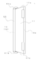
- FIG. 1 is a schematic front view of a fender structure according to a first embodiment of the present invention
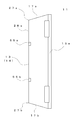
- FIG. 2 is a schematic right side view of the fender structure shown in FIG.
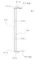
- FIG. 4 is a schematic plan view of the fender structure shown in FIG. 1, and
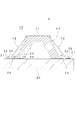
- FIG. 4 is a schematic sectional view taken along line IV-IV shown in FIG.
- the fender structure of the present invention can be installed so that the longitudinal direction is either the vertical direction or the horizontal direction.
- the fender structure 1 is made of an elastic material such as rubber, and shows the impact receiving portion 13 and the fender structure 1 for cushioning the impact of a ship (not shown) at the time of porting.
- the fender main body 11 includes quay wall attachment portions 19a and 19b for attaching to the quay, and an impact receiving portion cover body 41 made of the same elastic material as the fender structure 1 such as rubber.
- the impact receiving portion cover body 41 is detachably attached so as to cover the entire surface 14 (impact receiving surface) of the impact receiving portion 13 of the fender body 11. Detailed structures and the like of the fender body 11 and the impact receiving portion cover body 41 will be described later.
- the fender structure 1 has the quay wall mounting portions 19a and 19b arranged on the quay and is fixed by anchor bolts (not shown) using bolt mounting holes 20a to 20d and the like. That is, by embedding anchor bolts in the quay, inserting the anchor bolts into the bolt mounting holes 20a to 20d of the fender body 11 and screwing a nut (not shown) into the fender to secure the fender material.
- the structure 1 can be fixed to the quay.
- the impact receiving portion 13 of the fender main body 11 When a ship (not shown) comes in contact with the fender structure 1, the impact is absorbed by the impact receiving portion 13 of the fender main body 11, but the surface 14 of the impact receiving portion 13 has the impact receiving portion cover body 41. Since it is covered by the ship, it is difficult for the ship to come into direct contact with the fender body 11. As a result, the impact receiving section cover body 41, which has a higher frequency of direct contact with the ship than the fender body 11 is often damaged first. At this time, as described above, since the impact receiving body cover body 41 is detachably attached to the fender body 11, only the damaged impact receiving portion cover body 41 can be replaced. Therefore, the fender body 11 can be used for a long period of time, and the frequency of replacement of the entire fender structure 1 is reduced.
- FIG. 5 is a schematic front view of the fender body of the fender structure shown in FIG. 1
- FIG. 6 is a schematic right side view of the fender body shown in FIG. 5
- FIG. 5 is a schematic plan view of the fender body shown in FIG. 5
- FIG. 8 is a schematic sectional view taken along the line VIII-VIII shown in FIG.
- the fender body 11 has a substantially V-shape in plan view extending in the longitudinal direction and has a hollow portion 23 in which both longitudinal end portions 27a and 27b are open.
- first engaging portions 55a to 55d which are concave depressions, are provided on both ends 28a, 28b in the lateral direction of the impact receiving portion 13 of the fender body 11.
- Each of the first engaging portions 55a to 55d is arranged so as to engage with a second engaging portion provided on the impact receiving portion cover body described later.
- FIG. 9 is a schematic front view of the impact receiving portion cover body of the fender structure shown in FIG. 1, and FIG. 10 is a schematic rear view of the impact receiving portion cover body shown in FIG. 13 is a schematic right side view of the impact receiving portion cover body shown in FIG. 9, and FIG. 12 is a schematic plan view of a state in which the protective member of the impact receiving portion cover body shown in FIG. 9 is removed.
- FIG. 14 is a schematic bottom view of the impact receiving portion cover body shown in FIG. 9 with a protective member removed, and FIG. 14 is a schematic sectional view taken along line XIV-XIV shown in FIG. 10.
- the impact receiving portion cover body 41 has a substantially rectangular shape in a front view and a substantially trapezoidal shape in a plan view. Further, the back surface 46 of the impact-receiving section cover body 41, which is a surface in contact with the impact-receiving section 13 of the fender body 11, is hollowed out in accordance with the peripheral edge of the impact-receiving section 13 of the fender body 11 shown in FIG. ing. That is, the recess 50 is formed in the rear surface 46, and a part of the impact receiving portion 13 on the surface 14 side can be housed in the recess 50.
- a plurality of hemispherical projections 51 made of rubber or the like are provided at regular intervals on the back surface 46 (inner surface of the recess 50) of the impact receiving cover 41.
- the first engaging portions 55a to 55d shown in FIG. Four convex second engaging portions 56a to 56d corresponding to the shape are provided. As described above, each of the second engaging portions 56a to 56d engages with the first engaging portions 55a to 55d provided on the fender body 11 shown in FIG.
- the impact receiving portion cover body 41 has both ends 47a, 47b in the longitudinal direction (horizontal direction) as shown in FIGS. 9 and 11. Further, it is further provided with protection members 61a, 61b having a substantially semicylindrical shape. The protective members 61a and 61b cover a part of the side surface portions 17a and 17b of the corresponding fender body 11 on the impact receiving portion 13 side.
- fixing members 65 for fixing the impact receiving portion cover body 41 to the fender body 11 are attached to both longitudinal end portions 49a and 49b of the impact receiving portion cover body 41 on the back surface 46 side.
- the fixing member 65 includes a band 66 that is a flat string-shaped member made of rubber or the like, and a buckle 67 that is a string-shaped member fixing tool that fixes the band 66.
- the base end portion of the belt 66 is attached to the bottom surface side of the impact receiving portion cover body 41, and the buckle 67 is attached to the upper surface side thereof.
- the tip end portion of the band 66 is used for the hollow portion 23 of the fender body main body 11. It is inserted through the opening from the bottom side toward the opening on the upper side, and is passed through the buckle 67 to be fixed. At this time, the band 66 is tightened so as to follow the back surface 15 of the fender body 11 on the impact receiving portion 13 side. Then, the band 66 is arranged along the back surface on the impact receiving portion 13 side through the hollow portion 23.
- the band 66 can be removed from the buckle 67, so that the impact receiving portion cover body 41 can be easily attached and detached, and the fender structure 1 can be easily used.
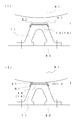
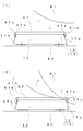
- FIG. 15 is a schematic diagram showing the function of the protrusions of the fender structure shown in FIG. 1, and (1) is a diagram showing a state before the ship is in contact with the fender structure. And (2) is a diagram showing a state in which the ship comes in contact with the fender structure and further moves in the horizontal direction.
- the fender structure 1 is installed on the quay 80 so that the longitudinal direction is perpendicular to the water surface.
- the front surface 14 of the impact receiving portion 13 of the fender body 11 and the tip of the protrusion 51 formed on the back surface 46 of the impact receiving portion cover body 41 are in contact with each other. is there.
- the impact receiving portion cover body 41 is pressed against the surface 14 of the impact receiving portion 13 of the fender body 11.
- the fender body 11 is made of an elastic material such as rubber, the surface 14 of the impact receiving portion 13 is deformed according to the surface shape of the projection 51 of the impact receiving portion cover body 41, and The surface area of the portion where the impact portion cover body 41 and the fender body 11 are in contact is increased. Therefore, the frictional force generated between the fender body 11 and the impact receiving portion cover body 41 becomes large.
- a horizontal force F 1 indicated by an arrow may be applied in accordance with the movement of the ship 81.
- the fender body 11 and the impact receiving portion cover body 41 are less likely to be displaced.
- FIG. 16 is a schematic view schematically showing the action of the engaging portion of the fender structure shown in FIG. 1, and (1) shows how the shearing force acts on the engaging portion. (2) shows a case where a force in a parallel direction generates a shearing force exceeding the second shearing strength generated in the impact receiving portion cover body.
- the shapes of the first engaging portion 55 and the second engaging portion 56 are simplified, and the formation position is changed to the central portion.
- the fender structure 1 is installed on the quay 80 so that the longitudinal direction is perpendicular to the water surface.
- the fender body 11 includes a first engaging portion 55, which is a concave recess, on the surface 14 of the impact receiving portion 13.
- the impact receiving portion cover body 41 has a convex second engaging portion 56 corresponding to the depression of the first engaging portion 55 on the back surface 46 which is a flat surface in contact with the impact receiving portion 13 of the fender body 11. Is equipped with.
- the first engaging portion 55 and the second engaging portion 56 are arranged so as to engage with each other.
- the shear strength S 2 of the shear strength S 1 and the impact receiving portion cover body 41 of the fender main body 11 are the same It can be said that
- the first force P 1 that causes shear fracture in the fender body 11 via the first engaging portion 55 is the second force. It is set to be larger than the second force P 2 that causes shear failure in the impact receiving portion cover body 41 via the engaging portion 56. This setting is possible, for example, by making the area of the area A 1 sufficiently larger than the area of the area A 2 .
- the second force P 2 is set to be larger than the first force P 1 .
- the force F 2 increases to F 3
- shear stress exceeding the shear strength S 1 of the fender body 11 may occur.
- the fender body 11 is destroyed in the area A 1 before the impact receiving portion cover body 41, and the fender body 11 is Will be damaged.
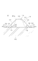
- FIG. 17 is a schematic diagram showing the action of the protective member of the fender structure shown in FIG. 1, and (1) is a diagram showing a state before the ship is in contact with the fender structure. And (2) is a view showing a state in which the ship is biased to one of the fender structure bodies and is ported.
- the fender structure 1 is installed on the quay 80 so that the longitudinal direction is parallel to the water surface.
- the marine vessel 81 may contact only a part of the fender structure 1 depending on the state of the marine vessel. 1
- the force may not be evenly applied to the entire body, but may be applied to only a part thereof.
- the fender structure 1 when a force is applied to one end portion 47a side of the impact receiving portion cover body 41 in the horizontal direction, the fender structure 1 has one end portion. The 47a side is largely deformed with respect to the other end 47b side. If the protection member 61a is not provided, the ship 81 may come into direct contact with the side surface portion 17a of the fender body 11 as indicated by the alternate long and short dash line. On the other hand, if there is the protection member 61a, the vessel 81 will come into contact with the protection member 61a first as shown by the solid line. As a result, the side surface portion 17a of the fender body 11 is protected by the protection member 61a, so that the side surface portion 17a of the fender body 11 can be less likely to be damaged by the port of the ship 81.
- the impact receiving portion cover body covers the entire surface of the impact receiving portion of the fender body, but it may cover at least a part of the surface of the impact receiving portion. Good.
- a plurality of protrusions are provided on the back surface of the impact receiving portion cover body, but the protrusions may be omitted.
- the plurality of protrusions provided on the back surface of the impact receiving portion cover body have a hemispherical shape, but may have another shape.
- the first engaging portion is provided on the impact receiving portion of the fender body
- the second engaging portion is provided on the plane of the impact receiving portion cover body that is in contact with the impact receiving portion of the fender material main body.
- the first engaging portion and the second engaging portion may not be provided.
- the recessed portion of the fender body is provided with four concave first engaging portions, and the flat surface of the impact receiving portion cover body is in contact with the impact portion of the fender body.
- the four convex second engaging portions are provided in the above, the present invention is not limited to this. At least one first engaging portion and at least one second engaging portion may be provided at positions corresponding to each other. Further, the first engaging portion may be formed in a convex shape and the second engaging portion may be formed in a concave shape.
- the protective member is provided at both ends in the longitudinal direction of the impact receiving cover body, but it may be provided at least at one of the longitudinal ends. Further, the protective member may not be provided.
- the protection member is a side surface portion of the fender body and covers a part of the side of the impact receiving portion, but as a configuration that covers the entire side surface portion of the fender body. Good.
- the cord-shaped member (band) of the fixing member and the cord-shaped member fixing tool (buckle) are provided, but the fixing member may be omitted.
- the cord-shaped member of the fixing member and the cord-shaped member fixing device are composed of the band and the buckle, but the invention is not limited to this.
- the string-like member is arranged on the back surface of the fender main body through the hollow part of the fender body and fixed by the string-like member fixing tool, other members such as a wire and a hook may be used.
- the cord-shaped member may be covered with rubber or resin, or may be covered with a tubular body made of rubber or resin.
- the position where the string-shaped member of the fixing member and the string-shaped member fixture are fixed is near one opening of the hollow portion of the fender body, but the fixed position is this. Not exclusively. For example, it may be fixed at another position such as near the center of the hollow portion.
- the fender body has the hollow portion, but the hollow portion may not be provided.
- the fender body has a substantially V-shape in plan view, but it can be similarly applied to fenders having other shapes such as a truncated cone shape.
- the impact receiving portion cover body has a rectangular shape in a front view and a substantially trapezoidal shape in a plan view, but may have another shape.
- the material of the fender body and the impact receiving portion cover body was rubber, but the material is not limited to this.
- the material of the impact receiving portion cover body is the same as that of the fender body, but it is replaced with a different material or different on the surface of the impact receiving portion cover body.
- the material may be added like a layer.
- the surface of the impact receiving portion cover body may be covered with ultra-high molecular weight polyethylene.
- ultrahigh-molecular polyethylene has a lower coefficient of friction than a rubber material, and the ship easily slips on the surface of the impact receiving portion cover at the time of porting, so that the risk of damaging the ship is reduced.
- the new fender body was premised, but it can be applied to the existing fender body as well.
- the impact receiving portion cover body with respect to the impact receiving surface of the fender body when an external force is applied regardless of the presence or absence of the protrusion and the first and second engaging portions. It may be a relative movement in the direction of deviation.
- the impact receiving portion cover body is displaced in the direction of displacement. It may be configured so as to move relatively. Thereby, when an excessive external force acts, the impact receiving portion cover body relatively moves to mitigate the influence of the external force, and the fender body can be prevented from being damaged.
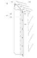
- FIG. 18 is a perspective view of the fender structure according to the second embodiment of the present invention attached to a quay
- FIG. 19 is an exploded perspective view of the fender structure shown in FIG. 20
- FIG. 20 is a cross-sectional view of the fender structure shown in FIG. 18, taken along line XX-XX.
- the impact receiving portion cover body 41 can be attached.
- the impact receiving portion cover body 41 covers at least a part of the surface (impacting surface) 14 of the impact receiving portion 13 of the fender body 12.
- a support portion 44 that is integrally provided on the cover main body portion 43 and is detachably fixed to the quay 80 and the like. Accordingly, by fixing the support portion 44 to the quay 80 or the like, the impact receiving portion cover body 41 can be attached to the fender body 12 so that the cover body portion 43 covers at least a part of the impact receiving surface 14. It is possible.
- the impact receiving portion cover body 41 is composed of a plurality of first to fifth cover units 42a to 42e. Since the first to fifth cover units 42a to 42e are formed in substantially the same form, the detailed description thereof will be represented by the description of the first cover unit 42a.
- the first cover unit 42a includes a cover main body 43 that is superposed on the impact receiving surface 14, and a pair of supports integrally provided on both sides of the cover main body 43 along the longitudinal direction of the fender main body 12. And a section 44.
- the cover main body 43 is formed in a trapezoidal cross section with an open rear side so that a part of the impact receiving surface 14 side can be accommodated.
- the first cover unit 42a located at the uppermost portion is attached to the cover body 43 at the upper end side of the fender body 12.
- a protection part 62 is provided to cover a part of the side surface part 18. The protective portion 62 is omitted in the second to fifth cover units 42b to 42e.
- the support portion 44 has a sheet-like shape extending from the cover main body portion 43 toward the quay 80 side, and an opening 57 for inserting an anchor bolt 30 to be described later is formed in a distal end side region thereof.
- two openings 57 are formed in one support portion 44.
- the pressing members 60a to 60e arranged on the support portion 44 for ensuring the fixed state to the quay 80 are provided for each of the support portions 44 of the first to fifth cover units 42a to 42e. Used.
- An opening 58 for inserting the anchor bolt 30 is also formed in each of the pressing members 60a to 60e.
- the anchor bolt 30 is embedded in advance near the fender body 12 on the quay 80 in accordance with the positions of the openings 57 formed in the support portions 44 of the first to fifth cover units 42a to 42e. Then, first, the cover main body 43 of the first cover unit 42a located at the uppermost position is superposed on the impact receiving portion 13, and the supporting portion 44 is inserted into the opening 57 of the anchor bolt 30, so that the quay 80. Place on the surface of. Next, the pressing member 60a is arranged on the support portion 44 by inserting the anchor bolt 30 into the opening 58 thereof. Then, the nut 32 is screwed into the anchor bolt 30 via the washer 31, and is tightened to fix the first cover unit 42a.
- the second cover unit 42b is fixed to the quay 80 so as to be adjacent to the first cover unit 42a by the same procedure as above.
- the third to fifth cover units 42c to 42e are sequentially fixed to the quay 80 so as to be adjacent to each other by the same procedure, so that the entire impact receiving surface 14 of the fender body 12 is covered. 41 is configured.
- the impact receiving portion cover body 41 of the present example is fixed to the fender body 12 by fixing the support portion 44 to the quay 80 so that the cover body portion 43 covers at least a part of the impact receiving surface 14. Since it can be attached, it can also be attached to the fender body 12 having no hollow portion.
- the size of the impact receiving section cover body 41 configured by the number of used cover units can be changed. That is, by using an appropriate number of cover units according to the size of the fender body 12, it is possible to properly cover the impact receiving surface 14 even with the fender body 12 having different lengths. Becomes Specifically, five cover units 42a to 42e were used for the fender body 12 shown in FIGS. 18 and 19, but the number of cover units used for the fender body 12 shorter than this Can be reduced to 4 or less, and if it is long, it can be dealt with by using 6 or more cover units.
- the impact receiving portion cover body 41 may be provided so as to be relatively difficult to move relative to the fender body 12, it receives the external force from the impact receiving surface 14 of the fender body 12. It may be configured so that it can be relatively moved in the direction of deviation. For example, by fixing the support portion 44 to the quay 80 in a state in which the impact receiving portion cover body 41 receives an external force, the cover main body portion 43 and the impact receiving surface 14 are fixed to the quay 80 in a state where the support portion 44 is slightly relaxed. It can be configured to be relatively movable in parallel directions.
- the condition for the relative movement of the impact receiving portion cover body 41 is, for example, that the component of the applied external force in the direction parallel to the impact receiving surface 14 exceeds the magnitude that causes shear damage to the fender body 12. It is possible to set it if Thereby, when an excessive external force is applied to the fender body, the impact receiving cover 41 is moved in the direction of displacement to reduce the external force and prevent the fender body 12 from being damaged. You can
- the impact receiving portion cover body 41 can be configured not to move relatively easily even if an external force is applied.
- FIG. 21 is a perspective view showing a state in which the fender structure according to the third embodiment of the present invention is attached to the quay.
- the impact receiving portion cover body 41 is manufactured in accordance with the length of the fender body 12 to form a single member.
- the pressing member 60 used when fixing the impact receiving portion cover body 41 to the quay 80 is also a long member adapted to the length of the fender body 12. Since the fender structure 3 of this example has a smaller number of constituent elements than the embodiment using the cover unit described above, the number of work steps at the time of installation can be reduced and the workability can be improved. .. Incidentally, the fender main body 12 having a different length may be dealt with by preparing the impact receiving portion cover body 41 having a different length.
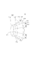
- FIG. 22 is a perspective view of the fender structure according to the fourth embodiment of the present invention
- FIG. 23 is an exploded perspective view of the fender structure shown in FIG. 22,
- FIG. FIG. 23 is a horizontal cross-sectional view of the fender structure shown in FIG. 22.
- the fender structure 4 is configured by attaching the impact receiving section cover body 70 to the fender body 21 having a truncated cone shape. It is a thing.
- the fender main body 21 of this example has a circular impact receiving surface 22 on the tip side and a mounting portion 24 formed on the base end side in the shape of a flange over the entire circumference.
- the impact receiving portion cover body 70 has a shallow frustoconical cover body portion 71 and a plurality of supporting portions provided so as to project from the peripheral edge portion thereof in accordance with the form of the fender body body 21. It is composed of 72.
- An opening 73 for inserting an anchor bolt, which will be described later, is formed on the tip end side of each support portion 72.
- the attachment of the impact receiving section cover body 70 is performed in the same procedure as in the second and third embodiments. That is, after the fender main body 21 is fixed to the quay 80 with the anchor bolts 25 and the nuts 26, each is formed in advance in the vicinity of the fender main body 21 on the quay 80 on the support 72 of the impact receiving portion cover body 70.
- the anchor bolt 30 is embedded according to the position of the opening 73.
- the cover body 71 of the impact receiving portion cover body 70 is placed on the impact receiving surface 22, and the supporting portion 72 is placed on the surface of the quay 80 by inserting the anchor bolt 30 into the opening 73.
- the nut 32 is screwed onto the anchor bolt 30 via the washer 31, and is tightened to fix the impact receiving portion cover body 70 to the quay 80 so as to cover the fender body 21. it can.
- the impact receiving portion cover body covers the entire impact receiving surface of the fender body, but covers at least a part of the impact receiving surface.
- the impact receiving portion cover body when the fender structure is subjected to an external force, the impact receiving portion cover body is relatively displaced in the direction in which it is displaced with respect to the impact surface of the fender body. It may be mobile. For example, when an external force is applied and the component of the external force in the direction parallel to the impact receiving surface exceeds the size that causes shear failure in the fender body, the impact receiving part cover body is used as the fender material. It can be configured to move relative to the body in a direction displaced.
- a plurality of protrusions may be provided on the back surface of the impact receiving portion cover body.
- the protrusion may have a hemispherical shape or another shape.
- the first engagement portion may be provided in the impact receiving portion of the fender body and the second engagement portion may be provided in the impact receiving portion cover body.
- one of the first engaging portion and the second engaging portion may be formed in a concave shape and the other may be formed in a convex shape.
- the number of the first engaging portions and the number of the second engaging portions may be, for example, four, but at least one may be provided.
- the first engaging portion and the second engaging portion cover the impact receiving portion cover before a shear failure occurs in the fender body when a force in a direction parallel to the impact receiving surface is applied to the impact receiving portion cover body.
- the second engaging portion of the body may be set to be shear-ruptured. This reduces the risk of damage to the fender body.
- a protective member may be provided on at least one of both end portions in the longitudinal direction of the impact receiving portion cover body or at least one end portion in the longitudinal direction.
- the protective member may be configured to cover a side surface of the fender body and a part of the side of the impact receiving portion or the entire side surface.
- the protection section may be in the form of the protection member of the first embodiment.
- the impact receiving portion cover body has a rectangular shape in a front view and a substantially trapezoidal shape in a plan view, but may have another shape.
- the fender body and the impact receiving portion cover body are made of rubber, but the present invention is not limited to this. Further, the impact receiving portion cover body and the fender body may be made of the same material or different materials.
- different materials may be added in layers on the surface of the impact receiving cover body.
- the surface of the impact receiving portion cover body may be covered with an ultra-high molecular weight polyethylene layer.
- Ultra-high molecular weight polyethylene has a lower coefficient of friction than rubber materials, and makes it easier for a ship to slip on the surface of the impact-receiving section cover at the time of porting.
- the second to fourth embodiments described above may be based on a new fender body, but can be applied to an existing fender body as well.
- the fender body may have a hollow portion or may have a V-shaped cross section.
- a fixing member including a string-shaped member and a string-shaped member fixture may be further provided.
- the fixing member may be made up of, for example, a wire and a hook, in addition to a band and a buckle.
- the string-shaped member may be covered with a tubular body covered with rubber or resin, or a tubular body made of rubber or resin. The position where the string-like member of the fixing member and the string-like member fixing tool are fixed may be near one opening of the hollow portion of the fender body, or near the center of the hollow portion.
- the fender structure according to the present invention can be applied not only to the fender body newly installed on the quay but also to the fender body already attached to the quay.
- the impact receiving portion cover body is attached to the existing fender body to construct the fender structure of the present invention. It is suitable.
- the present invention is applicable regardless of whether the longitudinal direction of the fender body is arranged horizontally or vertically. Further, the present invention can be applied to a case where the fender body is in a shape such as a truncated cone shape or a truncated pyramid shape having no longitudinal direction.
Landscapes
- Engineering & Computer Science (AREA)
- General Engineering & Computer Science (AREA)
- Ocean & Marine Engineering (AREA)
- Environmental & Geological Engineering (AREA)
- Mechanical Engineering (AREA)
- Civil Engineering (AREA)
- Structural Engineering (AREA)
- Body Structure For Vehicles (AREA)
- Refuge Islands, Traffic Blockers, Or Guard Fence (AREA)
- Vibration Dampers (AREA)
Abstract
Description
Claims (10)
- 岸壁(80)等に取り付けられる防舷材構造体(1)であって、
弾性材料からなり、船舶(81)の接舷時の衝撃を和らげるための受衝部(13)を含む防舷材本体(11)と、
弾性材料からなり、前記防舷材本体の前記受衝部の表面(14)の少なくとも一部を覆う受衝部カバー体(41)とを備え、
前記受衝部カバー体は、前記防舷材本体に分離自在に取り付けられる、防舷材構造体。 - 前記受衝部カバー体の少なくとも一部は、前記受衝部の受衝面(22)に対してずれる方向に相対移動可能である、請求項1記載の防舷材構造体。
- 前記防舷材本体は、両端が開放された中空部(23)を有し、
前記受衝部カバー体は、前記防舷材本体と前記受衝部カバー体とを固定するための固定部材(65)を更に備え、
前記固定部材は、前記受衝部カバー体の一方側に設けられた紐状部材(66)と前記受衝部カバー体の他方側に設けられ、前記紐状部材を固定するための紐状部材固定具(67)とからなり、
前記紐状部材は、前記中空部を介して前記受衝部の裏面(15)側に配置され、前記紐状部材固定具によって固定される、請求項1又は請求項2記載の防舷材構造体。 - 前記受衝部カバー体は、前記受衝面の少なくとも一部を覆うカバー本体部(43)と、このカバー本体部に一体的に設けられ、前記岸壁等に脱着自在に固定される支持部(44)とを備える、請求項1又は請求項2記載の防舷材構造体。
- 前記受衝部カバー体の前記防舷材本体の前記受衝部と接する面に複数の突起体(51)を設けた、請求項1から請求項4のいずれかに記載の防舷材構造体。
- 前記防舷材本体は、前記受衝部に少なくとも1つの凹又は凸形状の第1係合部(55a~55d)を備えると共に、前記受衝部カバー体は、前記防舷材本体の前記受衝部と接する平面に少なくとも1つの凸又は凹形状の第2係合部(56a~56d)とを更に備え、
前記第1係合部と前記第2係合部とは、互いに係合するように配置される、請求項1から請求項5のいずれかに記載の防舷材構造体。 - 前記防舷材本体の前記受衝部と接する平面に平行な方向の力が前記受衝部カバー体に加わった時において、前記第1係合部を介して前記防舷材本体にせん断破壊を生じさせる第1の前記力は、前記第2係合部を介して前記受衝部カバー体にせん断破壊を生じさせる第2の前記力より大きく設定される、請求項6記載の防舷材構造体。
- 前記受衝部カバー体は、前記防舷材本体の前記受衝部の全面を覆うと共に、水平方向の端部の少なくとも一方に対応する前記防舷材本体の側面部(17a、17b)であって前記受衝部側の少なくとも一部を覆う保護部材(61a、61b)を更に備えた、請求項1から請求項7のいずれかに記載の防舷材構造体。
- 前記受衝部カバー体は、前記防舷材本体の前記受衝部の全面を覆うと共に、前記防舷材本体の長手方向の少なくとも一方の側面部(27a、27b)における前記受衝部側の少なくとも一部を覆う保護部材を更に備えた、請求項1から請求項7のいずれかに記載の防舷材構造体。
- 前記受衝部カバー体は、複数のカバーユニット(42a~42e)から構成される、請求項1から請求項9のいずれかに記載の防舷材構造体。
Priority Applications (7)
| Application Number | Priority Date | Filing Date | Title |
|---|---|---|---|
| EP18943094.5A EP3896227B1 (en) | 2018-12-13 | 2018-12-13 | Fender structure |
| SG11202106093XA SG11202106093XA (en) | 2018-12-13 | 2018-12-13 | Fender structure |
| PCT/JP2018/045855 WO2020121472A1 (ja) | 2018-12-13 | 2018-12-13 | 防舷材構造体 |
| ES18943094T ES3050234T3 (en) | 2018-12-13 | 2018-12-13 | Fender structure |
| CN201880100156.3A CN113167040A (zh) | 2018-12-13 | 2018-12-13 | 护舷材构造体 |
| KR1020217017338A KR20210102242A (ko) | 2018-12-13 | 2018-12-13 | 방현재 구조체 |
| MYPI2021003166A MY208258A (en) | 2018-12-13 | 2018-12-13 | Fender structure |
Applications Claiming Priority (1)
| Application Number | Priority Date | Filing Date | Title |
|---|---|---|---|
| PCT/JP2018/045855 WO2020121472A1 (ja) | 2018-12-13 | 2018-12-13 | 防舷材構造体 |
Publications (1)
| Publication Number | Publication Date |
|---|---|
| WO2020121472A1 true WO2020121472A1 (ja) | 2020-06-18 |
Family
ID=71075695
Family Applications (1)
| Application Number | Title | Priority Date | Filing Date |
|---|---|---|---|
| PCT/JP2018/045855 Ceased WO2020121472A1 (ja) | 2018-12-13 | 2018-12-13 | 防舷材構造体 |
Country Status (7)
| Country | Link |
|---|---|
| EP (1) | EP3896227B1 (ja) |
| KR (1) | KR20210102242A (ja) |
| CN (1) | CN113167040A (ja) |
| ES (1) | ES3050234T3 (ja) |
| MY (1) | MY208258A (ja) |
| SG (1) | SG11202106093XA (ja) |
| WO (1) | WO2020121472A1 (ja) |
Families Citing this family (3)
| Publication number | Priority date | Publication date | Assignee | Title |
|---|---|---|---|---|
| KR102416551B1 (ko) | 2022-01-27 | 2022-07-05 | (주)동양기업 | 변곡부를 구비한 스풀타입 방현재 |
| KR102861717B1 (ko) | 2022-11-01 | 2025-09-18 | (주)동양기업 | 선박접안용 공기식 방현재 |
| KR20240067535A (ko) | 2022-11-09 | 2024-05-17 | (주)동양기업 | 선박접안용 공기식 방현재 |
Citations (9)
| Publication number | Priority date | Publication date | Assignee | Title |
|---|---|---|---|---|
| JPS498315Y1 (ja) * | 1969-11-18 | 1974-02-27 | ||
| JPS5681704A (en) * | 1979-12-05 | 1981-07-04 | Bridgestone Corp | Hollow drum shell type fender and manufacture thereof |
| JPS6051211A (ja) * | 1983-08-29 | 1985-03-22 | Yokohama Rubber Co Ltd:The | 防舷材 |
| JPS60104418U (ja) * | 1983-12-20 | 1985-07-16 | 横浜ゴム株式会社 | 浮遊式防舷材 |
| JPH08301188A (ja) | 1995-05-09 | 1996-11-19 | Masaki Yamamoto | キャップ式カラー防舷材 |
| JP2000309914A (ja) | 1999-04-27 | 2000-11-07 | Sumitomo Rubber Ind Ltd | 防舷材 |
| JP2002362480A (ja) * | 2001-05-31 | 2002-12-18 | Sekisui Plastics Co Ltd | 船首用保護装置 |
| JP2005090139A (ja) | 2003-09-18 | 2005-04-07 | Tsuneishi Shipbuilding Co Ltd | 防舷材カバー |
| JP2009150173A (ja) | 2007-12-21 | 2009-07-09 | Bridgestone Corp | 防舷材及びその製造方法 |
Family Cites Families (2)
| Publication number | Priority date | Publication date | Assignee | Title |
|---|---|---|---|---|
| JP4259730B2 (ja) * | 2000-06-07 | 2009-04-30 | 横浜ゴム株式会社 | 防舷施設用保護材 |
| KR100728150B1 (ko) | 2003-01-09 | 2007-06-13 | 가부시키가이샤 가네카 | 본딩 시트 및 한면 금속 클래드 적층판 |
-
2018
- 2018-12-13 ES ES18943094T patent/ES3050234T3/es active Active
- 2018-12-13 EP EP18943094.5A patent/EP3896227B1/en active Active
- 2018-12-13 WO PCT/JP2018/045855 patent/WO2020121472A1/ja not_active Ceased
- 2018-12-13 SG SG11202106093XA patent/SG11202106093XA/en unknown
- 2018-12-13 KR KR1020217017338A patent/KR20210102242A/ko not_active Ceased
- 2018-12-13 CN CN201880100156.3A patent/CN113167040A/zh active Pending
- 2018-12-13 MY MYPI2021003166A patent/MY208258A/en unknown
Patent Citations (9)
| Publication number | Priority date | Publication date | Assignee | Title |
|---|---|---|---|---|
| JPS498315Y1 (ja) * | 1969-11-18 | 1974-02-27 | ||
| JPS5681704A (en) * | 1979-12-05 | 1981-07-04 | Bridgestone Corp | Hollow drum shell type fender and manufacture thereof |
| JPS6051211A (ja) * | 1983-08-29 | 1985-03-22 | Yokohama Rubber Co Ltd:The | 防舷材 |
| JPS60104418U (ja) * | 1983-12-20 | 1985-07-16 | 横浜ゴム株式会社 | 浮遊式防舷材 |
| JPH08301188A (ja) | 1995-05-09 | 1996-11-19 | Masaki Yamamoto | キャップ式カラー防舷材 |
| JP2000309914A (ja) | 1999-04-27 | 2000-11-07 | Sumitomo Rubber Ind Ltd | 防舷材 |
| JP2002362480A (ja) * | 2001-05-31 | 2002-12-18 | Sekisui Plastics Co Ltd | 船首用保護装置 |
| JP2005090139A (ja) | 2003-09-18 | 2005-04-07 | Tsuneishi Shipbuilding Co Ltd | 防舷材カバー |
| JP2009150173A (ja) | 2007-12-21 | 2009-07-09 | Bridgestone Corp | 防舷材及びその製造方法 |
Non-Patent Citations (1)
| Title |
|---|
| See also references of EP3896227A4 |
Also Published As
| Publication number | Publication date |
|---|---|
| SG11202106093XA (en) | 2021-07-29 |
| KR20210102242A (ko) | 2021-08-19 |
| ES3050234T3 (en) | 2025-12-19 |
| EP3896227A4 (en) | 2022-07-20 |
| MY208258A (en) | 2025-04-29 |
| CN113167040A (zh) | 2021-07-23 |
| EP3896227B1 (en) | 2025-09-03 |
| EP3896227A1 (en) | 2021-10-20 |
Similar Documents
| Publication | Publication Date | Title |
|---|---|---|
| KR102225827B1 (ko) | 선박의 무링로프 보호장치 | |
| JP4478522B2 (ja) | 自発光式標識灯 | |
| US3680851A (en) | Fender with cushion board | |
| GB2438690A (en) | A fender for boats which includes an internal conduit | |
| KR20210102242A (ko) | 방현재 구조체 | |
| KR101480757B1 (ko) | 해저케이블 배전선로의 안전구조 | |
| JP4259730B2 (ja) | 防舷施設用保護材 | |
| JP2007168749A (ja) | 空気式防舷材の係留装置 | |
| JP7239971B2 (ja) | 防舷材構造体 | |
| JP2009167685A (ja) | 空気式防舷材の係留装置 | |
| KR100649105B1 (ko) | 항만 부두의 접안시설에 설치되는 충격흡수용 방현재 | |
| KR20170000268U (ko) | 선저플러그 파손방지장치 | |
| JP2009150173A (ja) | 防舷材及びその製造方法 | |
| KR20100003388U (ko) | 외면 돌부와 보강 로프를 형성한 방충 튜브 | |
| KR101332012B1 (ko) | 에어 펜더용 난연성 고무커버 | |
| US20060060122A1 (en) | Mooring rope protector which is intended, in particular, for a pleasure boat | |
| KR200303264Y1 (ko) | 선박 부착용 방현대 | |
| KR100989743B1 (ko) | 멀티 펜더를 이용한 선박의 안벽 계류 방법 | |
| KR102912854B1 (ko) | 해저케이블 등부표 선박 충돌 보호장치 | |
| JPH11201232A (ja) | 保護ガード材 | |
| KR200379585Y1 (ko) | 선박용 방현재 | |
| KR20050121489A (ko) | 충격흡수부재를 포함하는 고무방현재 | |
| KR960006596Y1 (ko) | 선박의 에어펜더(Air Fender)용 완충판 | |
| KR890000241Y1 (ko) | 부두용 방충제 | |
| JP2000008349A (ja) | 緩衝材 |
Legal Events
| Date | Code | Title | Description |
|---|---|---|---|
| 121 | Ep: the epo has been informed by wipo that ep was designated in this application |
Ref document number: 18943094 Country of ref document: EP Kind code of ref document: A1 |
|
| ENP | Entry into the national phase |
Ref document number: 20217017338 Country of ref document: KR Kind code of ref document: A |
|
| NENP | Non-entry into the national phase |
Ref country code: DE |
|
| ENP | Entry into the national phase |
Ref document number: 2018943094 Country of ref document: EP Effective date: 20210713 |
|
| NENP | Non-entry into the national phase |
Ref country code: JP |
|
| WWG | Wipo information: grant in national office |
Ref document number: 2018943094 Country of ref document: EP |