WO2020121476A1 - Émettteur - Google Patents
Émettteur Download PDFInfo
- Publication number
- WO2020121476A1 WO2020121476A1 PCT/JP2018/045868 JP2018045868W WO2020121476A1 WO 2020121476 A1 WO2020121476 A1 WO 2020121476A1 JP 2018045868 W JP2018045868 W JP 2018045868W WO 2020121476 A1 WO2020121476 A1 WO 2020121476A1
- Authority
- WO
- WIPO (PCT)
- Prior art keywords
- stored
- transmission data
- volatile memory
- selection information
- protocols
- Prior art date
- Legal status (The legal status is an assumption and is not a legal conclusion. Google has not performed a legal analysis and makes no representation as to the accuracy of the status listed.)
- Ceased
Links
Images



Classifications
-
- B—PERFORMING OPERATIONS; TRANSPORTING
- B60—VEHICLES IN GENERAL
- B60C—VEHICLE TYRES; TYRE INFLATION; TYRE CHANGING; CONNECTING VALVES TO INFLATABLE ELASTIC BODIES IN GENERAL; DEVICES OR ARRANGEMENTS RELATED TO TYRES
- B60C23/00—Devices for measuring, signalling, controlling, or distributing tyre pressure or temperature, specially adapted for mounting on vehicles; Arrangement of tyre inflating devices on vehicles, e.g. of pumps or of tanks; Tyre cooling arrangements
- B60C23/02—Signalling devices actuated by tyre pressure
- B60C23/04—Signalling devices actuated by tyre pressure mounted on the wheel or tyre
- B60C23/0408—Signalling devices actuated by tyre pressure mounted on the wheel or tyre transmitting the signals by non-mechanical means from the wheel or tyre to a vehicle body mounted receiver
- B60C23/0422—Signalling devices actuated by tyre pressure mounted on the wheel or tyre transmitting the signals by non-mechanical means from the wheel or tyre to a vehicle body mounted receiver characterised by the type of signal transmission means
- B60C23/0433—Radio signals
- B60C23/0435—Vehicle body mounted circuits, e.g. transceiver or antenna fixed to central console, door, roof, mirror or fender
- B60C23/0438—Vehicle body mounted circuits, e.g. transceiver or antenna fixed to central console, door, roof, mirror or fender comprising signal transmission means, e.g. for a bidirectional communication with a corresponding wheel mounted receiver
- B60C23/0442—Vehicle body mounted circuits, e.g. transceiver or antenna fixed to central console, door, roof, mirror or fender comprising signal transmission means, e.g. for a bidirectional communication with a corresponding wheel mounted receiver the transmitted signal comprises further information, e.g. instruction codes, sensor characteristics or identification data
-
- B—PERFORMING OPERATIONS; TRANSPORTING
- B60—VEHICLES IN GENERAL
- B60C—VEHICLE TYRES; TYRE INFLATION; TYRE CHANGING; CONNECTING VALVES TO INFLATABLE ELASTIC BODIES IN GENERAL; DEVICES OR ARRANGEMENTS RELATED TO TYRES
- B60C23/00—Devices for measuring, signalling, controlling, or distributing tyre pressure or temperature, specially adapted for mounting on vehicles; Arrangement of tyre inflating devices on vehicles, e.g. of pumps or of tanks; Tyre cooling arrangements
- B60C23/02—Signalling devices actuated by tyre pressure
- B60C23/04—Signalling devices actuated by tyre pressure mounted on the wheel or tyre
- B60C23/0408—Signalling devices actuated by tyre pressure mounted on the wheel or tyre transmitting the signals by non-mechanical means from the wheel or tyre to a vehicle body mounted receiver
-
- B—PERFORMING OPERATIONS; TRANSPORTING
- B60—VEHICLES IN GENERAL
- B60C—VEHICLE TYRES; TYRE INFLATION; TYRE CHANGING; CONNECTING VALVES TO INFLATABLE ELASTIC BODIES IN GENERAL; DEVICES OR ARRANGEMENTS RELATED TO TYRES
- B60C23/00—Devices for measuring, signalling, controlling, or distributing tyre pressure or temperature, specially adapted for mounting on vehicles; Arrangement of tyre inflating devices on vehicles, e.g. of pumps or of tanks; Tyre cooling arrangements
- B60C23/02—Signalling devices actuated by tyre pressure
- B60C23/04—Signalling devices actuated by tyre pressure mounted on the wheel or tyre
- B60C23/0408—Signalling devices actuated by tyre pressure mounted on the wheel or tyre transmitting the signals by non-mechanical means from the wheel or tyre to a vehicle body mounted receiver
- B60C23/0422—Signalling devices actuated by tyre pressure mounted on the wheel or tyre transmitting the signals by non-mechanical means from the wheel or tyre to a vehicle body mounted receiver characterised by the type of signal transmission means
- B60C23/0433—Radio signals
- B60C23/0447—Wheel or tyre mounted circuits
- B60C23/0455—Transmission control of wireless signals
- B60C23/0462—Structure of transmission protocol
-
- B—PERFORMING OPERATIONS; TRANSPORTING
- B60—VEHICLES IN GENERAL
- B60C—VEHICLE TYRES; TYRE INFLATION; TYRE CHANGING; CONNECTING VALVES TO INFLATABLE ELASTIC BODIES IN GENERAL; DEVICES OR ARRANGEMENTS RELATED TO TYRES
- B60C23/00—Devices for measuring, signalling, controlling, or distributing tyre pressure or temperature, specially adapted for mounting on vehicles; Arrangement of tyre inflating devices on vehicles, e.g. of pumps or of tanks; Tyre cooling arrangements
- B60C23/02—Signalling devices actuated by tyre pressure
- B60C23/04—Signalling devices actuated by tyre pressure mounted on the wheel or tyre
- B60C23/0408—Signalling devices actuated by tyre pressure mounted on the wheel or tyre transmitting the signals by non-mechanical means from the wheel or tyre to a vehicle body mounted receiver
- B60C23/0471—System initialisation, e.g. upload or calibration of operating parameters
-
- B—PERFORMING OPERATIONS; TRANSPORTING
- B60—VEHICLES IN GENERAL
- B60C—VEHICLE TYRES; TYRE INFLATION; TYRE CHANGING; CONNECTING VALVES TO INFLATABLE ELASTIC BODIES IN GENERAL; DEVICES OR ARRANGEMENTS RELATED TO TYRES
- B60C23/00—Devices for measuring, signalling, controlling, or distributing tyre pressure or temperature, specially adapted for mounting on vehicles; Arrangement of tyre inflating devices on vehicles, e.g. of pumps or of tanks; Tyre cooling arrangements
- B60C23/02—Signalling devices actuated by tyre pressure
- B60C23/04—Signalling devices actuated by tyre pressure mounted on the wheel or tyre
- B60C23/0408—Signalling devices actuated by tyre pressure mounted on the wheel or tyre transmitting the signals by non-mechanical means from the wheel or tyre to a vehicle body mounted receiver
- B60C23/0481—System diagnostic, e.g. monitoring battery voltage, detecting hardware detachments or identifying wireless transmission failures
-
- B—PERFORMING OPERATIONS; TRANSPORTING
- B60—VEHICLES IN GENERAL
- B60C—VEHICLE TYRES; TYRE INFLATION; TYRE CHANGING; CONNECTING VALVES TO INFLATABLE ELASTIC BODIES IN GENERAL; DEVICES OR ARRANGEMENTS RELATED TO TYRES
- B60C23/00—Devices for measuring, signalling, controlling, or distributing tyre pressure or temperature, specially adapted for mounting on vehicles; Arrangement of tyre inflating devices on vehicles, e.g. of pumps or of tanks; Tyre cooling arrangements
- B60C23/02—Signalling devices actuated by tyre pressure
- B60C23/04—Signalling devices actuated by tyre pressure mounted on the wheel or tyre
- B60C23/0486—Signalling devices actuated by tyre pressure mounted on the wheel or tyre comprising additional sensors in the wheel or tyre mounted monitoring device, e.g. movement sensors, microphones or earth magnetic field sensors
-
- B—PERFORMING OPERATIONS; TRANSPORTING
- B60—VEHICLES IN GENERAL
- B60R—VEHICLES, VEHICLE FITTINGS, OR VEHICLE PARTS, NOT OTHERWISE PROVIDED FOR
- B60R16/00—Electric or fluid circuits specially adapted for vehicles and not otherwise provided for; Arrangement of elements of electric or fluid circuits specially adapted for vehicles and not otherwise provided for
- B60R16/02—Electric or fluid circuits specially adapted for vehicles and not otherwise provided for; Arrangement of elements of electric or fluid circuits specially adapted for vehicles and not otherwise provided for electric constitutive elements
- B60R16/023—Electric or fluid circuits specially adapted for vehicles and not otherwise provided for; Arrangement of elements of electric or fluid circuits specially adapted for vehicles and not otherwise provided for electric constitutive elements for transmission of signals between vehicle parts or subsystems
- B60R16/027—Electric or fluid circuits specially adapted for vehicles and not otherwise provided for; Arrangement of elements of electric or fluid circuits specially adapted for vehicles and not otherwise provided for electric constitutive elements for transmission of signals between vehicle parts or subsystems between relatively movable parts of the vehicle, e.g. between steering wheel and column
-
- H—ELECTRICITY
- H04—ELECTRIC COMMUNICATION TECHNIQUE
- H04L—TRANSMISSION OF DIGITAL INFORMATION, e.g. TELEGRAPHIC COMMUNICATION
- H04L9/00—Cryptographic mechanisms or cryptographic arrangements for secret or secure communications; Network security protocols
- H04L9/40—Network security protocols
-
- H—ELECTRICITY
- H04—ELECTRIC COMMUNICATION TECHNIQUE
- H04W—WIRELESS COMMUNICATION NETWORKS
- H04W4/00—Services specially adapted for wireless communication networks; Facilities therefor
- H04W4/30—Services specially adapted for particular environments, situations or purposes
- H04W4/40—Services specially adapted for particular environments, situations or purposes for vehicles, e.g. vehicle-to-pedestrians [V2P]
- H04W4/44—Services specially adapted for particular environments, situations or purposes for vehicles, e.g. vehicle-to-pedestrians [V2P] for communication between vehicles and infrastructures, e.g. vehicle-to-cloud [V2C] or vehicle-to-home [V2H]
Definitions
- the present invention relates to a transmitter.
- the tire condition monitoring device described in Patent Document 1 includes a transmitter mounted on wheels and a receiver.
- the transmitter includes a pressure sensor that detects tire pressure, a transmitter, and a controller that controls the transmitter.
- the transmission unit transmits transmission data including the detection result detected by the pressure sensor. Since the protocol differs depending on the receiver, a transmitter of a model corresponding to the protocol of the receiver is selected and mounted on the wheel.
- a nonvolatile memory stores a plurality of types of protocols
- a volatile memory stores selection information.
- the selection information is information indicating one protocol selected from a plurality of types of protocols.
- the control unit transmits the transmission data according to the protocol indicated by the selection information. By selecting the protocol corresponding to the receiver, the transmitter can correspond to a plurality of types of receivers.
- the selection information is stored in a volatile memory and the selection information can be rewritten. If the selection information stored in the volatile memory is unintentionally deleted, the transmission data cannot be transmitted by the protocol corresponding to the receiver, and the reception data may not be able to be received by the receiver. ..
- An object of the present invention is to provide a transmitter that allows a receiver to receive transmission data even when the selection information stored in a volatile memory is erased.
- a transmitter mounted on each of a plurality of wheels provided in a vehicle and transmitting transmission data to a receiver.
- the transmitter is a non-volatile memory storing a plurality of types of protocols, and a protocol selected from the plurality of types of protocols stored in the non-volatile memory, the information indicating a protocol corresponding to the receiver.
- the transmission unit transmits the transmission data according to the protocol indicated by the selection information, and the selection information is not stored in the volatile memory. In this case, the transmission data according to all the protocols stored in the nonvolatile memory is transmitted.
- the transmission data according to all the protocols stored in the non-volatile memory is transmitted. Any one of all protocols is a protocol compatible with the receiver. Therefore, even if the selection information stored in the volatile memory is erased, the receiver can be made to receive the transmission data.
- the transmitter may be assigned a code corresponding to each of the plurality of types of protocols, and the selection information may be a code corresponding to a protocol selected from the plurality of types of protocols.
- the transmitter includes information indicating that selection information is not stored in the volatile memory when transmitting the transmission data according to all the protocols stored in the nonvolatile memory. However, the transmission data may be transmitted.
- the receiver can be made aware that the selection information is not stored in the volatile memory.
- the receiver can be made to receive the transmission data.
- the schematic block diagram of a tire condition monitoring device The schematic block diagram of a transmitter.
- the tire condition monitoring device 20 includes a transmitter 21 mounted on each of four wheels 11 of the vehicle 10 and a receiver 40 installed in the vehicle 10.
- Each wheel 11 includes a wheel 12 and a tire 13 mounted on the wheel 12.
- a transmitter fixed to the tire valve or a transmitter fixed to the wheel 12 or the tire 13 is used.
- the transmitter 21 is attached to the wheel 11 so as to be arranged in the internal space of the tire 13.
- the transmitter 21 detects the state of the corresponding tire 13, for example, the air pressure of the tire 13 or the temperature inside the tire 13, and wirelessly transmits the transmission data including the detection result to the receiver 40.
- the tire condition monitoring device 20 receives the transmission data transmitted from the transmitter 21 at the receiver 40 and monitors the condition of the tire 13.
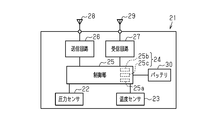
- the transmitter 21 includes a pressure sensor 22, a temperature sensor 23, a control unit 25, a transmission circuit 26, a transmission antenna 28, a reception circuit 27, a reception antenna 29, and a battery 30.
- the battery 30 serves as a power source of the transmitter 21.
- the pressure sensor 22 detects the pressure (air pressure) of the corresponding tire 13.
- the pressure sensor 22 outputs the detection result to the control unit 25.
- the temperature sensor 23 detects the temperature inside the corresponding tire 13.
- the temperature sensor 23 outputs the detection result to the control unit 25.
- the control unit 25 is composed of a microcomputer including the CPU 25a and the storage unit 24.
- the storage unit 24 includes a non-volatile memory 25b and a volatile memory 25c.
- the non-volatile memory 25b stores an ID code which is unique identification information of each transmitter 21, and various programs for controlling the transmitter 21.
- the control unit 25 may include dedicated hardware (application-specific integrated circuit: ASIC) that executes at least a part of various processes. That is, the control unit 25 includes 1) one or more processors operating according to a computer program (software), 2) one or more dedicated hardware circuits such as ASIC, or 3) a circuit including a combination thereof. Can be configured as The processor includes a CPU and memories such as RAM and ROM. The memory stores program code or instructions configured to cause the CPU to perform processing. Memory or computer readable media includes any available media that can be accessed by a general purpose or special purpose computer.
- ASIC application-specific integrated circuit
- a plurality of types of protocols are stored in a predetermined storage area of the non-volatile memory 25b. That is, the non-volatile memory 25b stores information about frame formats and procedures corresponding to a plurality of protocols.
- FIG. 3 shows an example in which three protocols, protocol A, protocol B, and protocol C, are stored as an example, the transmitter 21 is used as the number of protocols stored in the nonvolatile memory 25b. It depends on the type of vehicle you get.
- FIG. 4 shows an example of the frame format defined by Protocol A.
- the frame format is a format of transmission data to be sent to the receiver 40, and can be said to be a format of what information each bit forming the transmission data indicates.
- the frame format includes synchronization bits, identification information, status, flags, pressure data, temperature data, and error correction code.
- the sync bit is data for synchronizing transmission and reception.
- the identification information is data indicating an ID code.
- the status is data indicating the state of the transmitter 21.
- the error correction code is data indicating an error correction code and an error detection code.
- the flag is data indicating whether or not an abnormality has occurred in the transmitter 21. For example, the flag is 1-bit data that becomes 0 when the transmitter 21 has no abnormality and 1 when the transmitter 21 has abnormality.
- the frame format defined by the protocols B and C includes a synchronization bit, identification information, a status, a flag, pressure data, temperature data, and an error correction code, like the protocol A.
- the order of flags, pressure data, and temperature data is different. That is, which bit of the transmission data indicates the flag, the pressure data, and the temperature data is different.
- selection information which is information indicating a protocol selected from a plurality of types of protocols, is stored in a predetermined storage area of the volatile memory 25c.
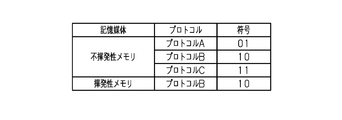
- a code represented by a binary data string is given to each of the protocols A, B, and C, and the code corresponding to the selected protocol is stored in the volatile memory 25c.
- 01 is associated with protocol A
- 10 is associated with protocol B
- 11 is associated with protocol C.
- 10 corresponding to the protocol B is stored in the volatile memory 25c. Therefore, it can be seen that the protocol B is selected from the protocols A, B, and C.
- the value of the predetermined storage area when the selection information is not stored is 00.
- the protocol stored in the volatile memory 25c that is, one protocol selected from a plurality of types of protocols is set corresponding to the protocol of the receiver 40. If the protocol is different, the frame format and the procedure are different, and unless the transmission data corresponds to the protocol of the receiver 40, the transmission data cannot be received by the receiver 40. It should be noted that the receiver 40 differs depending on the vehicle model, and it can be said that the frame format differs depending on the vehicle model.
- the selection information is written in the volatile memory 25c by an external device such as a trigger device.
- the control unit 25 generates transmission data according to the protocol and outputs it to the transmission circuit 26.
- the transmission circuit 26 as a transmission unit modulates the transmission data from the control unit 25 to generate a radio signal (RF signal) and transmits it from the transmission antenna 28.
- the control unit 25 generates transmission data including a tire state (tire pressure and tire internal temperature) and an ID code, which are the detection result of the pressure sensor 22 and the detection result of the temperature sensor 23, and uses a signal including the transmission data. Send a radio signal.
- the control unit 25 has a diagnostic function for diagnosing a failure of the pressure sensor 22 or the temperature sensor 23.
- the diagnosis function determines that the pressure sensor 22 or the temperature sensor 23 is out of order
- the transmission data includes data for causing the receiver 40 to recognize the abnormality of the pressure sensor 22 and the temperature sensor 23.
- the failure diagnosis of the pressure sensor 22 and the temperature sensor 23 is performed using the detection results of the pressure sensor 22 and the temperature sensor 23, for example.
- the detection results of the pressure sensor 22 and the temperature sensor 23 are obtained by converting an analog signal into a digital signal using an AD converter provided in the control unit 25. At this time, if the AD converter overflows or underflows, the control unit 25 determines that the pressure sensor 22 or the temperature sensor 23 is out of order.
- the control unit 25 can also detect disconnection or short circuit of the pressure sensor 22 and the temperature sensor 23.
- the receiving circuit 27 receives a signal transmitted from an external device such as a trigger device via the receiving antenna 29.
- This signal includes a command to the transmitter 21, and the control unit 25 executes processing according to the command. Thereby, it is possible to write the selection information to the volatile memory 25c.
- control unit 25 periodically transmits the transmission data to the receiver 40.
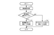
- the control unit 25 acquires the detection result from the pressure sensor 22 and the temperature sensor 23.
- step S2 the control unit 25 determines whether or not the selection information is stored in the volatile memory 25c.
- the selection information is not stored in the volatile memory 25c, it is considered that the selection information stored in the volatile memory 25c has been erased due to reset of the control unit 25, external noise such as a strong electric field, or software malfunction.
- the control unit 25 is reset by, for example, detecting a malfunction by the watchdog timer, when the temperature of the control unit 25 excessively rises, when data stored in the volatile memory 25c has an error, or when the voltage of the battery 30 is reduced. Is significantly reduced.
- the control unit 25 detects whether the reset is performed or confirms whether the selection information is stored in the volatile memory 25c to determine whether the selection information is stored in the volatile memory 25c. Whether or not can be determined.
- step S2 When the process of step S2 is affirmative, the control unit 25 performs the process of step S3. When the process of step S2 is negative, the control unit 25 performs the process of step S4.
- step S3 the control unit 25 generates transmission data in a frame format according to the protocol indicated by the selection information stored in the volatile memory 25c, and transmits the transmission data. That is, when the selection information is stored in the volatile memory 25c, the transmission data according to the protocol selected based on the selection information is transmitted.
- the control unit 25 since the code corresponding to the protocol is stored as the selection information, the control unit 25 reads the protocol corresponding to the code stored in the volatile memory 25c from the non-volatile memory 25b, and transmits the transmission data. Generate. Since the protocol selected based on the selection information corresponds to the receiver 40, the receiver 40 can be made to receive the transmission data.
- step S4 the control unit 25 generates transmission data in a frame format according to all protocols stored in the non-volatile memory 25b and transmits the transmission data. That is, when the selection information is not stored in the volatile memory 25c, the transmission data according to all the protocols stored in the non-volatile memory 25b is transmitted.
- the control unit 25 When generating data, the control unit 25 generates transmission data with a flag set, that is, with the flag set to 1.
- the flag being 1 can be said to be information indicating that the selection information is not stored in the volatile memory 25c.
- transmission data when transmission data is transmitted according to all protocols, transmission data may be transmitted according to all protocols at one transmission timing.
- the same number of transmission data as the number of protocols stored in the non-volatile memory 25b is stored. It is transmitted at one transmission timing.
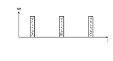
- transmission data when transmission data is transmitted according to all protocols, transmission data may be transmitted according to different protocols for each transmission timing. In this case, every time the transmission data is transmitted, the transmission data is generated according to different protocols and the transmission data is transmitted. As a result, the transmission data according to each protocol is sequentially transmitted.
- the transmission data may be periodically transmitted in the order of transmission of transmission data according to protocol A ⁇ transmission of transmission data according to protocol B ⁇ transmission of transmission data according to protocol C. Good.
- the receiver 40 includes a receiver control unit 41, a receiver receiving circuit 42, and a receiving antenna 43.
- An alarm device 44 is connected to the receiver control unit 41.
- the receiver control unit 41 includes a microcomputer including a receiver CPU 41a and a receiver storage unit 41b (ROM, RAM, etc.).
- the receiver reception circuit 42 demodulates the transmission data received from each transmitter 21 via the reception antenna 43, and outputs the demodulated transmission data to the receiver control unit 41.
- the ID code of the transmitter 21 mounted on each wheel 11 is stored in the receiver storage unit 41b. As a result, the transmitter 21 and the receiver 40 are associated with each other.
- the receiver control unit 41 collates the ID code included in the transmission data received by the receiver reception circuit 42 with the ID code stored in the receiver storage unit 41b. When the ID code included in the transmission data matches the registered ID code as a result of the matching, the receiver control unit 41 adopts the data included in the transmission data.
- the receiver control unit 41 grasps the state of the tire 13 from the data included in the transmission data transmitted from the transmitter 21 associated with the receiver 40.
- the receiver control unit 41 When the pressure of the tire 13 is lower than the threshold value or when the receiver control unit 41 recognizes that an abnormality has occurred in the transmitter 21 due to the flag included in the received transmission data, the receiver control unit 41 outputs an alarm (alarm). ) 44.
- the alarm device 44 for example, a device that notifies by lighting or blinking light, or a device that notifies by sound is used. Further, the receiver control unit 41 may display the state of the tire 13 on a display device that can be visually recognized by a passenger of the vehicle 10. It should be noted that the alarm device 44 may be separately provided with a device that gives a notification when an abnormality occurs in the tire 13 and a device that gives a notification when an abnormality occurs in the transmitter 21. In addition, one alarm device 44 may notify the abnormality of the tire 13 and the abnormality alarm of the transmitter 21.
- the transmitter 21 transmits the transmission data according to the protocol corresponding to the receiver 40. This allows the receiver 40 to receive the transmission data.
- the transmitter 21 transmits the transmission data according to all the protocols stored in the non-volatile memory 25b.
- any one of a plurality of types of protocols stored in the non-volatile memory 25b corresponding to the receiver 40 is selected and mounted on the wheel 11. It can be said that any one of all the protocols is a protocol corresponding to the receiver 40. Therefore, if transmission data is transmitted according to all protocols, any transmission data becomes transmission data that can be received by the receiver 40.
- the tire 13 may have an abnormal pressure such as an excessive decrease in pressure. However, it is not possible to make a notification to that effect.
- the receiver 40 can be made to receive the transmission data, so the selection information is erased from the volatile memory 25c. Even if an abnormality occurs in the tire 13 after the failure, it is possible to notify that fact.
- the receiver 40 can be made to recognize the abnormality of the transmitter 21 by the flag of the transmission data.
- the receiver 40 receives the transmission data whose flag is 1, the alarm 40 gives an alarm.
- the control unit 25 transmits the transmission data according to all the protocols stored in the nonvolatile memory 25b. Even when the selection information stored in the volatile memory 25c is erased, the receiver 40 can be made to receive the transmission data.
- the control unit 25 When the selection information is not stored in the volatile memory 25c, the control unit 25 generates transmission data including information indicating that the selection information is not stored in the volatile memory 25c. Therefore, it is possible to make the receiver 40 recognize that the selection information is not stored in the volatile memory 25c. In the present embodiment, the receiver 40 gives an alarm by the alarm device 44 when the selection information is not stored in the volatile memory 25c. Therefore, the passenger can be notified that the transmitter 21 has an abnormality.
- the flag used when the pressure sensor 22 or the temperature sensor 23 is abnormal is also used as a flag indicating that selection information is not stored. Therefore, when the existing frame format has a flag used for an abnormality such as the pressure sensor 22 or the temperature sensor 23, it is notified that the selection information is not stored without changing the frame format. You can
- the power consumption can be reduced by transmitting the transmission data according to all the protocols only when the selection information is erased from the volatile memory 25c. it can. Therefore, it is possible to suppress the life of the battery 30 from being shortened as compared with the case where the transmission data complying with all the protocols is constantly transmitted.
- the selection information is often stored in the volatile memory 25c. Therefore, compared with the case where the selection information is stored in a rewritable non-volatile memory such as an EEPROM or a flash memory, it is not necessary to change the hardware, and an increase in manufacturing cost can be suppressed.
- the embodiment may be modified as follows.
- the control unit 25 does not have to transmit the transmission data including the information indicating that the selection information is not stored in the volatile memory 25c.
- the data of the protocol itself may be stored in the volatile memory 25c instead of the code associated with the plurality of types of protocols.
- the control unit 25 reads the protocol stored in the volatile memory 25c and generates transmission data.
- control unit 25 may transmit the transmission data in plural times. For example, it is assumed that eight types of protocols A, B, C, D, E, F, G, and H are stored in the nonvolatile memory 25b as protocols.
- the transmission data is transmitted according to the four protocols at one transmission timing, and then the transmission data is transmitted according to the remaining four protocols. Good.
- the control unit 25 may transmit the transmission data according to all the protocols by repeating this.
- the transmission frequency of transmission data may be different for multiple protocols. For example, when transmitting the transmission data according to the four protocols at one transmission timing, two of the four protocols are fixed, and the remaining two protocols are changed at each transmission timing. Good.
- the transmission data may be transmitted in the order of protocol A, B, C, D ⁇ protocol A, B, E, F ⁇ protocol A, B, G, H.
- the protocols A and B a protocol suitable for the receiver 40 having a large number of distributions is selected.
- the type of protocol and the number of protocols may be changed for each transmission timing.
- the transmission data may be transmitted according to the four protocols at the next transmission timing after the transmission data is transmitted according to the three protocols.
- the protocols When transmitting transmission data according to a plurality of types of protocols at one transmission timing, the protocols may be randomly selected. Further, even when all the protocols are not transmitted in a plurality of times, the frequency of the protocol, the type of the protocol transmitted at the transmission timing of one time, etc. may be appropriately changed.
- the interval between transmission timings at which transmission data is transmitted need not be constant. In this case, the intervals between the transmission timings may be randomly determined.
- the value of the volatile memory 25c when selection information is not stored may be other than 00. That is, the value of the volatile memory 25c when the selection information is not stored may be any value as long as it is a value stored when the control unit 25 is reset.
- the same data may be stored in a plurality of storage areas.
- the data in the corresponding storage areas are referenced, and if the data are different, the data is erroneously inadvertently reset, or the correct data is obtained by majority. It becomes possible to judge.
- control unit 25 can send the transmission data according to the protocol specified by the selection information when the selection information is stored, and the transmission data according to all the protocols when the selection information is not stored, You may perform a process in such a procedure.
- the transmitter 21 may be one that can detect one of the states of the tire 13. For example, it is possible to detect either the pressure of the tire 13 or the temperature of the tire 13.
- the state of the tire 13 detected by the transmitter 21 may be other than pressure or temperature.
- the transmitter 21 may be provided with a sensor according to the state desired to be detected.
- the transmission data may include a dedicated flag for making the receiver 40 recognize that the selection information is not stored in the volatile memory 25c. That is, the data for causing the receiver 40 to recognize the abnormality of the pressure sensor 22 and the temperature sensor 23 is different from the data for causing the receiver 40 to recognize that the selection information is not stored in the volatile memory 25c. Good.
- the transmission interval of transmission data, the resolution of pressure data and temperature data, the type of data included in the frame format, etc. may be different for each protocol.
- the vehicle may be a two-wheeled vehicle or a vehicle including five or more wheels 11.
- the receiver 40 may be a mobile terminal carried by a passenger of the vehicle 10.
Landscapes
- Engineering & Computer Science (AREA)
- Mechanical Engineering (AREA)
- Computer Networks & Wireless Communication (AREA)
- Computer Security & Cryptography (AREA)
- Signal Processing (AREA)
- Arrangements For Transmission Of Measured Signals (AREA)
- Small-Scale Networks (AREA)
- Communication Control (AREA)
Abstract
L'invention concerne un émetteur qui est monté sur chaque roue d'une pluralité de roues disposées sur un véhicule et qui transmet des données de transmission à un récepteur. L'émetteur est pourvu : d'une mémoire non volatile dans laquelle au moins deux types de protocoles ont été stockés ; d'une mémoire volatile qui stocke des informations de sélection qui sont des informations indiquant un protocole sélectionné parmi les au moins deux types de protocoles stockés dans la mémoire non volatile, ce protocole correspondant au récepteur ; et d'une unité de transmission qui transmet des données de transmission en fonction du protocole. Lorsque les informations de sélection ont été stockées dans la mémoire volatile, l'unité de transmission transmet des données de transmission en fonction du protocole indiqué par ces informations de sélection ; et lorsqu'aucune information de sélection n'a été stockée dans la mémoire volatile, l'unité de transmission transmet des données de transmission en fonction de l'ensemble des protocoles stockés dans la mémoire non volatile.
Priority Applications (5)
| Application Number | Priority Date | Filing Date | Title |
|---|---|---|---|
| US17/297,638 US12036824B2 (en) | 2018-12-13 | 2018-12-13 | Transmitter |
| EP18942999.6A EP3896914B1 (fr) | 2018-12-13 | 2018-12-13 | Émettteur |
| CN201880099981.6A CN113169905B (zh) | 2018-12-13 | 2018-12-13 | 发送机 |
| PCT/JP2018/045868 WO2020121476A1 (fr) | 2018-12-13 | 2018-12-13 | Émettteur |
| JP2020559637A JP7026261B2 (ja) | 2018-12-13 | 2018-12-13 | 送信機 |
Applications Claiming Priority (1)
| Application Number | Priority Date | Filing Date | Title |
|---|---|---|---|
| PCT/JP2018/045868 WO2020121476A1 (fr) | 2018-12-13 | 2018-12-13 | Émettteur |
Publications (1)
| Publication Number | Publication Date |
|---|---|
| WO2020121476A1 true WO2020121476A1 (fr) | 2020-06-18 |
Family
ID=71076189
Family Applications (1)
| Application Number | Title | Priority Date | Filing Date |
|---|---|---|---|
| PCT/JP2018/045868 Ceased WO2020121476A1 (fr) | 2018-12-13 | 2018-12-13 | Émettteur |
Country Status (5)
| Country | Link |
|---|---|
| US (1) | US12036824B2 (fr) |
| EP (1) | EP3896914B1 (fr) |
| JP (1) | JP7026261B2 (fr) |
| CN (1) | CN113169905B (fr) |
| WO (1) | WO2020121476A1 (fr) |
Citations (6)
| Publication number | Priority date | Publication date | Assignee | Title |
|---|---|---|---|---|
| JP2004145474A (ja) * | 2002-10-22 | 2004-05-20 | Yokohama Rubber Co Ltd:The | タイヤモニタリングシステム並びにそのモニタ受信機とモニタ装置及びセンサ装置 |
| JP2010533612A (ja) * | 2007-07-03 | 2010-10-28 | コンティネンタル オートモーティブ システムズ ユーエス, インコーポレイティッド | 汎用タイヤ圧監視センサ |
| JP2012071755A (ja) * | 2010-09-29 | 2012-04-12 | Tokai Rika Co Ltd | タイヤ空気圧監視システムの受信機 |
| US20130038440A1 (en) * | 2011-08-09 | 2013-02-14 | Continental Automotive Systems Us, Inc. | Tire Pressure Monitoring Apparatus And Method |
| JP2014091344A (ja) | 2012-10-31 | 2014-05-19 | Yokohama Rubber Co Ltd:The | タイヤ状態監視システムおよび監視装置 |
| WO2018011954A1 (fr) * | 2016-07-14 | 2018-01-18 | 太平洋工業 株式会社 | Dispositif de détection d'état de pneumatique |
Family Cites Families (22)
| Publication number | Priority date | Publication date | Assignee | Title |
|---|---|---|---|---|
| JP3510164B2 (ja) * | 1999-10-06 | 2004-03-22 | トヨタ自動車株式会社 | 車輪状態情報供給装置および車輪状態情報供給・受信装置 |
| CN100375026C (zh) * | 2005-09-13 | 2008-03-12 | 联想(北京)有限公司 | 快速存储设备软件的安装/更新方法 |
| JP4748196B2 (ja) * | 2008-09-17 | 2011-08-17 | ブラザー工業株式会社 | 無線通信装置、識別子出力方法及びプログラム |
| WO2010096965A1 (fr) * | 2009-02-27 | 2010-09-02 | 华为技术有限公司 | Procédé, dispositif terminal et serveur de commutation de canaux pour le traitement d'anomalies en commutation de canaux |
| JP4737727B2 (ja) * | 2009-06-26 | 2011-08-03 | 横浜ゴム株式会社 | タイヤ状態取得装置及びタイヤ状態監視システム |
| US8301822B2 (en) * | 2009-09-23 | 2012-10-30 | Sandisk Il Ltd. | Multi-protocol storage device bridge |
| US8659412B2 (en) * | 2009-12-10 | 2014-02-25 | Continental Automotive Systems, Inc. | Tire pressure monitoring apparatus and method |
| US9676238B2 (en) * | 2011-08-09 | 2017-06-13 | Continental Automotive Systems, Inc. | Tire pressure monitor system apparatus and method |
| KR101844425B1 (ko) * | 2011-09-26 | 2018-04-04 | 삼성전자주식회사 | 응용 프로그램의 프로토콜을 재구성하는 방법 및 장치 |
| US20130203400A1 (en) * | 2011-11-16 | 2013-08-08 | Flextronics Ap, Llc | On board vehicle presence reporting module |
| CN102594643B (zh) * | 2012-03-12 | 2015-11-25 | 北京经纬恒润科技有限公司 | 一种控制器局域网总线通讯控制方法、装置及系统 |
| CN102917127B (zh) * | 2012-10-15 | 2014-07-16 | 北京推博信息技术有限公司 | 一种音频传输方法及系统 |
| US9974287B2 (en) * | 2013-08-08 | 2018-05-22 | Nelson Development Group, LLC | Snapping fish stringer |
| JP6149806B2 (ja) * | 2014-06-10 | 2017-06-21 | トヨタ自動車株式会社 | ハイブリッド車両 |
| JP6128143B2 (ja) | 2015-02-18 | 2017-05-17 | トヨタ自動車株式会社 | タイヤ空気圧モニタシステム |
| US9522579B1 (en) * | 2015-06-02 | 2016-12-20 | Continental Automotive Systems, Inc. | Tire pressure monitoring sensor |
| CN106612466B (zh) * | 2015-10-27 | 2019-07-09 | 北京国双科技有限公司 | 数据采集方法和装置 |
| US10310298B2 (en) * | 2016-10-25 | 2019-06-04 | GM Global Technology Operations LLC | Smart sensor-cover apparatus and methods and computer products for implementing same |
| DE102016225496A1 (de) * | 2016-12-19 | 2018-06-21 | Continental Automotive Gmbh | Elektronische Radeinheit und Steuereinrichtung für ein Radüberwachungssystem eines Fahrzeuges, Radüberwachungssystem für ein Fahrzeug sowie Verfahren zur Radüberwachung in einem Fahrzeug |
| CN107512142B (zh) * | 2017-09-05 | 2021-07-06 | 南京矽力微电子技术有限公司 | 代码写入装置、胎压监测单元及控制方法 |
| EP3521069B1 (fr) * | 2017-12-05 | 2023-03-08 | Pacific Industrial Co., Ltd. | Émetteur et dispositif de surveillance d'état de pneu |
| CN108446247B (zh) * | 2018-02-08 | 2021-02-09 | 深圳太极云软技术有限公司 | 一种数据交互的方法及终端 |
-
2018
- 2018-12-13 WO PCT/JP2018/045868 patent/WO2020121476A1/fr not_active Ceased
- 2018-12-13 US US17/297,638 patent/US12036824B2/en active Active
- 2018-12-13 CN CN201880099981.6A patent/CN113169905B/zh active Active
- 2018-12-13 EP EP18942999.6A patent/EP3896914B1/fr active Active
- 2018-12-13 JP JP2020559637A patent/JP7026261B2/ja active Active
Patent Citations (6)
| Publication number | Priority date | Publication date | Assignee | Title |
|---|---|---|---|---|
| JP2004145474A (ja) * | 2002-10-22 | 2004-05-20 | Yokohama Rubber Co Ltd:The | タイヤモニタリングシステム並びにそのモニタ受信機とモニタ装置及びセンサ装置 |
| JP2010533612A (ja) * | 2007-07-03 | 2010-10-28 | コンティネンタル オートモーティブ システムズ ユーエス, インコーポレイティッド | 汎用タイヤ圧監視センサ |
| JP2012071755A (ja) * | 2010-09-29 | 2012-04-12 | Tokai Rika Co Ltd | タイヤ空気圧監視システムの受信機 |
| US20130038440A1 (en) * | 2011-08-09 | 2013-02-14 | Continental Automotive Systems Us, Inc. | Tire Pressure Monitoring Apparatus And Method |
| JP2014091344A (ja) | 2012-10-31 | 2014-05-19 | Yokohama Rubber Co Ltd:The | タイヤ状態監視システムおよび監視装置 |
| WO2018011954A1 (fr) * | 2016-07-14 | 2018-01-18 | 太平洋工業 株式会社 | Dispositif de détection d'état de pneumatique |
Non-Patent Citations (1)
| Title |
|---|
| See also references of EP3896914A4 |
Also Published As
| Publication number | Publication date |
|---|---|
| EP3896914B1 (fr) | 2023-12-06 |
| US20220032696A1 (en) | 2022-02-03 |
| JPWO2020121476A1 (ja) | 2021-10-28 |
| JP7026261B2 (ja) | 2022-02-25 |
| EP3896914A1 (fr) | 2021-10-20 |
| CN113169905A (zh) | 2021-07-23 |
| EP3896914A4 (fr) | 2022-08-17 |
| CN113169905B (zh) | 2022-07-05 |
| US12036824B2 (en) | 2024-07-16 |
Similar Documents
| Publication | Publication Date | Title |
|---|---|---|
| JP6030098B2 (ja) | 異なる通信プロトコルを用いてシグナルを送受するシグナルトランスポンダ、及び異なる通信プロトコルを用いてシグナルを送受するための方法 | |
| US9308783B2 (en) | Tire pressure monitoring device | |
| EP2741928B1 (fr) | Appareil et procédé de surveillance de pression de pneu | |
| JP3842495B2 (ja) | タイヤ空気圧監視装置 | |
| JP2006117143A (ja) | 通信システムおよび車輪側無線送信装置 | |
| JP6728158B2 (ja) | タイヤ状態検出装置 | |
| EP3521069B1 (fr) | Émetteur et dispositif de surveillance d'état de pneu | |
| WO2012160780A1 (fr) | Dispositif de détection de la pression d'un pneumatique | |
| JP5629659B2 (ja) | バルブid登録システム | |
| CN204354736U (zh) | 带有自动缩放压力分辨率的轮胎压力监测车轮单元 | |
| JP3061047B1 (ja) | タイヤ空気圧警報装置 | |
| CN110114229B (zh) | 发送器、触发器、发送器的模式设定系统、以及发送器的模式设定方法 | |
| JP6536471B2 (ja) | タイヤ空気圧監視システム及び監視装置 | |
| TWI492864B (zh) | Can be equipped with a variety of different communication protocols to receive the device | |
| JP7026261B2 (ja) | 送信機 | |
| WO2018157510A1 (fr) | Dispositif de surveillance de pression de pneu et procédé de verrouillage | |
| JP4082345B2 (ja) | 車輪状態検出装置、車輪及び車体 | |
| JP6568824B2 (ja) | タイヤ状態検出装置 | |
| TW202042162A (zh) | 胎壓偵測器的無線燒錄方法 | |
| JP5808354B2 (ja) | タイヤ圧力監視装置 | |
| JP2017087802A (ja) | 空気圧監視システム及び監視装置 | |
| JP2012236527A (ja) | バルブid登録システム |
Legal Events
| Date | Code | Title | Description |
|---|---|---|---|
| 121 | Ep: the epo has been informed by wipo that ep was designated in this application |
Ref document number: 18942999 Country of ref document: EP Kind code of ref document: A1 |
|
| ENP | Entry into the national phase |
Ref document number: 2020559637 Country of ref document: JP Kind code of ref document: A |
|
| NENP | Non-entry into the national phase |
Ref country code: DE |
|
| ENP | Entry into the national phase |
Ref document number: 2018942999 Country of ref document: EP Effective date: 20210713 |