WO2020121568A1 - Pneumatique radial pour véhicule à passagers - Google Patents
Pneumatique radial pour véhicule à passagers Download PDFInfo
- Publication number
- WO2020121568A1 WO2020121568A1 PCT/JP2019/027039 JP2019027039W WO2020121568A1 WO 2020121568 A1 WO2020121568 A1 WO 2020121568A1 JP 2019027039 W JP2019027039 W JP 2019027039W WO 2020121568 A1 WO2020121568 A1 WO 2020121568A1
- Authority
- WO
- WIPO (PCT)
- Prior art keywords
- tire
- less
- width
- noise
- cross
- Prior art date
- Legal status (The legal status is an assumption and is not a legal conclusion. Google has not performed a legal analysis and makes no representation as to the accuracy of the status listed.)
- Ceased
Links
Images

Classifications
-
- B—PERFORMING OPERATIONS; TRANSPORTING
- B60—VEHICLES IN GENERAL
- B60C—VEHICLE TYRES; TYRE INFLATION; TYRE CHANGING; CONNECTING VALVES TO INFLATABLE ELASTIC BODIES IN GENERAL; DEVICES OR ARRANGEMENTS RELATED TO TYRES
- B60C3/00—Tyres characterised by the transverse section
- B60C3/04—Tyres characterised by the transverse section characterised by the relative dimensions of the section, e.g. low profile
-
- B—PERFORMING OPERATIONS; TRANSPORTING
- B60—VEHICLES IN GENERAL
- B60C—VEHICLE TYRES; TYRE INFLATION; TYRE CHANGING; CONNECTING VALVES TO INFLATABLE ELASTIC BODIES IN GENERAL; DEVICES OR ARRANGEMENTS RELATED TO TYRES
- B60C19/00—Tyre parts or constructions not otherwise provided for
- B60C19/002—Noise damping elements provided in the tyre structure or attached thereto, e.g. in the tyre interior
-
- B—PERFORMING OPERATIONS; TRANSPORTING
- B60—VEHICLES IN GENERAL
- B60C—VEHICLE TYRES; TYRE INFLATION; TYRE CHANGING; CONNECTING VALVES TO INFLATABLE ELASTIC BODIES IN GENERAL; DEVICES OR ARRANGEMENTS RELATED TO TYRES
- B60C5/00—Inflatable pneumatic tyres or inner tubes
- B60C5/002—Inflatable pneumatic tyres or inner tubes filled at least partially with foam material
-
- B—PERFORMING OPERATIONS; TRANSPORTING
- B60—VEHICLES IN GENERAL
- B60C—VEHICLE TYRES; TYRE INFLATION; TYRE CHANGING; CONNECTING VALVES TO INFLATABLE ELASTIC BODIES IN GENERAL; DEVICES OR ARRANGEMENTS RELATED TO TYRES
- B60C9/00—Reinforcements or ply arrangement of pneumatic tyres
- B60C9/02—Carcasses
- B60C9/04—Carcasses the reinforcing cords of each carcass ply arranged in a substantially parallel relationship
- B60C9/08—Carcasses the reinforcing cords of each carcass ply arranged in a substantially parallel relationship the cords extend transversely from bead to bead, i.e. radial ply
-
- B—PERFORMING OPERATIONS; TRANSPORTING
- B60—VEHICLES IN GENERAL
- B60C—VEHICLE TYRES; TYRE INFLATION; TYRE CHANGING; CONNECTING VALVES TO INFLATABLE ELASTIC BODIES IN GENERAL; DEVICES OR ARRANGEMENTS RELATED TO TYRES
- B60C2200/00—Tyres specially adapted for particular applications
- B60C2200/04—Tyres specially adapted for particular applications for road vehicles, e.g. passenger cars
Definitions
- the present invention relates to a pneumatic radial tire for passenger cars.
- Patent Document 1 The applicant has proposed various narrow and large-diameter pneumatic radial tires for passenger cars in which the tire cross-section width SW and the tire outer diameter OD have a predetermined relationship (for example, Patent Document 1).
- an object of the present invention is to provide a pneumatic radial tire for a passenger car, which has improved noise control.
- the pneumatic radial tire for passenger cars of the present invention is A pneumatic radial tire for a passenger vehicle, which comprises a carcass consisting of a ply of a radial arrangement cord, straddling toroidally between a pair of bead portions,
- the sectional width SW of the tire is less than 165 (mm)
- the ratio SW/OD of the sectional width SW of the tire and the outer diameter OD is 0.26 or less
- the inner surface of the tire is provided with one or more noise dampers,
- the circumferential length of the noise damper is L (mm) and the cross-sectional area of the noise damper is S (mm 2 )
- the ratio L (mm)/S (mm 2 ) is 0.02 or more. It is characterized by being 5 or less.
- the “circumferential length” is the peripheral length along the inner surface of the tire, and when the noise damper extends intermittently in the tire circumferential direction, it means the total peripheral length. To do.
- the pneumatic radial tire for passenger cars of the present invention is A pneumatic radial tire for a passenger vehicle, which comprises a carcass consisting of a ply of a radial arrangement cord, straddling toroidally between a pair of bead portions,
- the sectional width SW of the tire is 165 (mm) or more, and the sectional width SW (mm) and the outer diameter OD (mm) of the tire are expressed by a relational expression, OD (mm) ⁇ 2.135 ⁇ SW (mm)+282.3
- the inner surface of the tire is provided with one or more noise dampers, When the circumferential length of the noise damper is L (mm) and the cross-sectional area of the noise damper is S (mm 2 ), the ratio L (mm)/S (mm 2 ) is 0.02 or more. It is characterized by being 5 or less.
- the pneumatic radial tire for passenger cars of the present invention is A pneumatic radial tire for a passenger vehicle, which comprises a carcass consisting of a ply of a radial arrangement cord, straddling toroidally between a pair of bead portions,
- the sectional width SW (mm) and outer diameter OD (mm) of the tire are expressed by a relational expression, OD (mm) ⁇ -0.0187 x SW (mm) 2 +9.15 x SW (mm)-380
- the inner surface of the tire is provided with one or more noise dampers, When the circumferential length of the noise damper is L (mm) and the cross-sectional area of the noise damper is S (mm 2 ), the ratio L (mm)/S (mm 2 ) is 0.02 or more. It is characterized by being 5 or less.
- the "rim” is an industrial standard that is effective in regions where tires are produced and used.
- JATMA Joint Auto Tire Association
- ETRTO European Tire
- STANDARDS MANUAL Rim Technical Organization
- TRA The Tire and Rim Association, Inc.
- TRA Rim Technical Organization
- standard rims for application sizes ETRTO STANDARDS MANUALS
- Measuring Rim, Design Rim in YEAR BOOK of TRA includes not only the current size but also a size that may be included in the industry standard in the future. "It will be described in the future.
- the size includes sizes described as “FUTURE DEVELOPMENTS” in the ETRTO 2013 edition.) However, in the case of a size not listed in the above industrial standard, the size corresponds to the bead width of the tire. The width of the rim.
- the “specified internal pressure” refers to the air pressure (maximum air pressure) corresponding to the maximum load capacity of a single wheel in the applicable size and ply rating described in JATMA, etc.
- the “specified internal pressure” means the air pressure (maximum air pressure) corresponding to the maximum load capacity specified for each vehicle in which the tire is mounted.
- the “maximum load capacity” described later means a load corresponding to the maximum load capacity.
- the “ground contact end” means both ends in the tire width direction of the ground contact surface which is in contact with the road surface when the tire is incorporated into a rim, a specified internal pressure is filled, and a maximum load is applied.
- FIG. 3 is a cross-sectional view in the tire width direction showing a pneumatic radial tire for passenger cars according to an embodiment of the first to third aspects of the present invention.
- FIG. 1 is a schematic diagram showing a sectional width SW and an outer diameter OD of a tire.
- a pneumatic radial tire for passenger cars (hereinafter, also simply referred to as a tire) according to an embodiment of the first aspect of the present invention has a tire sectional width SW of less than 165 (mm), and a tire sectional width SW and an outer diameter.
- the ratio SW/OD with OD is 0.26 or less, and the shape is narrow and large in diameter.
- the rolling resistance can be reduced by suppressing the deformation of the tread rubber near the ground contact surface of the tire, which can improve the fuel economy of the tire.
- the SW/OD is preferably 0.25 or less, more preferably 0.24 or less.
- the above ratio is preferably satisfied when the internal pressure of the tire is 200 kPa or more, more preferably 220 kPa or more, and more preferably 280 kPa or more. Is more preferable. This is because the rolling resistance can be reduced.
- the above ratio is preferably satisfied when the internal pressure of the tire is 350 kPa or less. This is because the riding comfort can be improved.
- the sectional width SW of the tire is preferably 105 mm or more, more preferably 125 mm or more, and further preferably 135 mm or more in the range satisfying the above ratio. It is preferably 145 mm or more and particularly preferably.
- the sectional width SW of the tire is preferably 155 mm or less in the range satisfying the above ratio from the viewpoint of reducing the air resistance.
- the outer diameter OD of the tire is preferably 500 mm or more, more preferably 550 mm or more, and further preferably 580 mm or more in the range satisfying the above ratio. ..
- the outer diameter OD of the tire is preferably 800 mm or less, more preferably 720 mm or less, and further preferably 650 mm or less in the range satisfying the above ratio. It is preferably 630 mm or less, and particularly preferably 630 mm or less. Further, from the viewpoint of reducing rolling resistance, the rim diameter is preferably 16 inches or more, and more preferably 17 inches or more when the sectional width SW and the outer diameter OD of the tire satisfy the above ratio. More preferably, it is 18 inches or more.
- the rim diameter is preferably 22 inches or less, and more preferably 21 inches or less when the sectional width SW and the outer diameter OD of the tire satisfy the above ratio. 20 inches or less is more preferable, and 19 inches or less is particularly preferable. Further, the flatness of the tire is more preferably 45 to 70, and further preferably 45 to 65 when the sectional width SW and the outer diameter OD of the tire satisfy the above ratios.
- the specific tire size is not particularly limited, but as an example, 105/50R16, 115/50R17, 125/55R20, 125/60R18, 125/65R19, 135/45R21, 135/55R20, 135/60R17.
- the tire of one embodiment in the second aspect of the present invention has a tire cross-section width SW of 165 (mm) or more, and the tire cross-section width SW (mm) and outer diameter OD (mm) are expressed by a relational expression, OD (mm) ⁇ 2.135 ⁇ SW (mm)+282.3 It has a narrow width and a large diameter.
- the sectional width SW and the outer diameter OD of the tire satisfy the above relational expression, and the ratio SW/OD is preferably 0.26 or less, and is 0.25 or less. More preferably, it is more preferably 0.24 or less.
- the above relational expression and/or ratio is preferably satisfied when the internal pressure of the tire is 200 kPa or more, more preferably 220 kPa or more, and more preferably 280 kPa or more. More preferably, it is satisfied. This is because the rolling resistance can be reduced. On the other hand, it is preferable that the above relational expressions and/or ratios are satisfied when the internal pressure of the tire is 350 kPa or less. This is because the riding comfort can be improved.
- the sectional width SW of the tire is preferably 175 mm or more, and more preferably 185 mm or more, in the range satisfying the above relational expression, from the viewpoint of ensuring the ground contact area.
- the sectional width SW of the tire is preferably 230 mm or less, more preferably 215 mm or less, and more preferably 205 mm or less in the range satisfying the above relational expression. More preferably, it is particularly preferably 195 mm or less.
- the outer diameter OD of the tire is preferably 630 mm or more, and more preferably 650 mm or more, in the range satisfying the above relational expression.
- the outer diameter OD of the tire is preferably 800 mm or less, more preferably 750 mm or less, and even more preferably 720 mm or less in the range satisfying the above relational expression.
- the rim diameter is preferably 18 inches or more, and more preferably 19 inches or more when the sectional width SW and the outer diameter OD of the tire satisfy the above relational expressions. ..
- the rim diameter is preferably 22 inches or less, and more preferably 21 inches or less when the tire sectional width SW and the outer diameter OD satisfy the above relational expressions.
- the flatness of the tire is preferably 45 to 70, more preferably 45 to 65.
- the specific tire size is not particularly limited, but as an example, 165/45R22, 165/55R18, 165/55R19, 165/55R20, 165/55R21, 165/60R19, 165/65R19, 165/70R18. 175/45R23, 175/55R19, 175/55R20, 175/55R22, 175/60R18, 185/45R22, 185/50R20, 185/55R19, 185/55R20, 185/60R19, 185/60R20, 195/50R20, 195 /55R20, 195/60R19, 205/50R21, 205/55R20, 215/50R21.
- the sectional width SW (mm) and the outer diameter OD (mm) of the tire are expressed by a relational expression, OD (mm) ⁇ -0.0187 x SW (mm) 2 +9.15 x SW (mm)-380 It has a narrow width and a large diameter.
- the air resistance can be reduced and the rolling resistance can be reduced, whereby the fuel efficiency of the tire can be improved.
- the sectional width SW and the outer diameter OD of the tire satisfy the above relational expression, and the ratio SW/OD is preferably 0.26 or less, and is 0.25 or less. More preferably, it is more preferably 0.24 or less.
- the above relational expression and/or ratio is preferably satisfied when the internal pressure of the tire is 200 kPa or more, more preferably 220 kPa or more, and more preferably 280 kPa or more. More preferably, it is satisfied. This is because the rolling resistance can be reduced. On the other hand, it is preferable that the above relational expressions and/or ratios are satisfied when the internal pressure of the tire is 350 kPa or less. This is because the riding comfort can be improved.
- the tire cross-section width SW is preferably 105 mm or more, more preferably 125 mm or more, and more preferably 135 mm or more in the range satisfying the above relational expression. More preferably, it is more preferably 145 mm or more.
- the sectional width SW of the tire is preferably 230 mm or less, more preferably 215 mm or less, and more preferably 205 mm or less in the range satisfying the above relational expression. More preferably, it is particularly preferably 195 mm or less.
- the outer diameter OD of the tire is preferably 500 mm or more, more preferably 550 mm or more, and further preferably 580 mm or more in the range satisfying the above relational expression.
- the outer diameter OD of the tire is preferably 800 mm or less, more preferably 750 mm or less, and even more preferably 720 mm or less in the range satisfying the above relational expression. More preferable.
- the rim diameter is preferably 16 inches or more, and more preferably 17 inches or more when the sectional width SW and the outer diameter OD of the tire satisfy the above relational expressions. And more preferably 18 inches or more.
- the rim diameter is preferably 22 inches or less, and more preferably 21 inches or less when the tire sectional width SW and the outer diameter OD satisfy the above relational expressions. It is preferably 20 inches or less. Further, the flatness of the tire is more preferably 45 to 70, and further preferably 45 to 65 when the sectional width SW and the outer diameter OD of the tire satisfy the above ratios.
- the specific tire size is not particularly limited, but as an example, 105/50R16, 115/50R17, 125/55R20, 125/60R18, 125/65R19, 135/45R21, 135/55R20, 135/60R17.
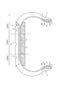
- FIG. 2 is a sectional view in the tire width direction showing a pneumatic radial tire for passenger cars according to an embodiment of the first to third aspects of the present invention.
- FIG. 2 shows a cross-section in the width direction of the tire when the tire is incorporated into a rim, a specified internal pressure is filled, and no load is applied.
- the tire 1 is provided with a carcass 3 made of a ply of a radial arrangement cord, which extends in a toroidal manner between a pair of bead portions 2.
- the tire 1 is provided with a belt 4 and a tread 5, which are two layers of belt layers 4a and 4b in the illustrated example, in that order on the tire radial outside of the carcass 3.
- a bead core 2a is embedded in each of the pair of bead portions 2.
- the cross-sectional shape and the material of the bead core 2a are not particularly limited, and the bead core 2a may have a configuration normally used in a pneumatic radial tire for passenger cars.
- the bead core 2a may be divided into a plurality of small bead cores.
- the bead core 2a may be omitted.
- the tire 1 in the illustrated example has a bead filler 2b having a substantially triangular cross section on the tire radial outside of the bead core 2a.
- the cross-sectional shape of the bead filler 2b is not limited to this example, and the material is not particularly limited. Alternatively, it is possible to reduce the weight of the tire by using the configuration without the bead filler 2b.
- the tire width direction cross-sectional area S1 of the bead filler 2b is preferably 1 to 4 times the tire width direction cross-sectional area S2 of the bead core 2a.
- the ratio Ts/Tb of the gauge Ts of the sidewall portion and the bead width (width of the bead portion 2 in the tire width direction) Tb at the tire radial center of the bead core 2a is preferably 15% or more and 40% or less. ..
- the ratio Ts/Tb By setting the ratio Ts/Tb to 15% or more, the rigidity of the sidewall portion can be secured.
- the ratio Ts/Tb to 40% or less, the tire can be made lighter and the fuel economy can be improved.
- the gauge Ts is the total thickness of all the members such as rubber, the reinforcing member, and the inner liner (however, even if the noise suppressor 9 is also arranged on the inner surface of the sidewall portion, 9 does not include the thickness).
- the “sidewall portion” is an outer side in the tire width direction of the ground contact end E, and is a tire radial direction outer end of the bead portion from the ground contact end E (in the case where the bead filler 2b is provided, a tire radial direction of the bead filler 2b).
- the bead filler 2b In the case where the bead filler 2b is not provided at the outer end, it means a tire radial direction region extending to the tire radial outer end of the bead core 2a.
- the distance between the innermost end and the outermost end in the tire width direction of all the small bead cores is Tb.
- the ratio Ts/Tc of the gauge Ts of the sidewall portion at the tire maximum width position and the diameter Tc of the carcass cord is 5 or more and 10 or less.
- the maximum tire width position is, for example, in the range of 50% to 90% in terms of tire cross-sectional height from the bead base line (imaginary line that passes through the bead base and is parallel to the tire width direction) to the tire radial outside. Can be provided.
- the "bead portion” refers to a portion in the tire radial region from the rim baseline to the tire radial outermost end of the bead filler when it has a bead filler, and when it does not have a bead filler, The portion in the tire radial direction region from the baseline to the tire radial outermost end of the bead core.
- the tire 1 may have a structure having a rim guard.
- the bead portion 2 may be further provided with an additional member such as a rubber layer or a cord layer for the purpose of reinforcement or the like.
- Such an additional member can be provided at various positions with respect to the carcass 3 and the bead filler 2b.
- the carcass 3 is composed of one carcass ply.
- the number of carcass plies is not particularly limited, and may be two or more.
- the carcass 3 includes a carcass body portion 3a that straddles between the pair of bead portions 2 in a toroidal shape, and a folded portion 3b that is folded from the carcass body portion 3a around the bead core 2a.
- the carcass folded-back portion 3b may be wound around the bead core 2a or may be sandwiched between a plurality of divided small bead cores.
- the end 3c of the carcass folded-back portion 3b is located outside the tire radial direction outer end of the bead filler 2b in the tire radial direction and inside the tire maximum width position in the tire radial direction.
- the end 3c of the carcass folded-back portion 3b may be located on the tire radial direction inner side from the tire radial direction outer end of the bead filler 2b, or on the tire radial direction outer side from the tire maximum width position. It may be located.
- the end 3c of the carcass folded-back portion 3b is positioned inside the tire width direction from the end of the belt 4 (for example, the end of the belt layer 4b) so as to be located between the carcass body 2a and the belt 4 in the tire radial direction. It may also be an envelope structure. Further, when the carcass 3 is composed of a plurality of carcass plies, the positions (for example, tire radial direction positions) of the ends 3c of the carcass folded-back portions 3b may be the same or different between the carcass plies. .
- the number of cords to be driven into the carcass 3 is not particularly limited, but may be, for example, 20 to 60 cords/50 mm. Further, various structures can be adopted for the carcass line.
- the carcass maximum width position can be brought closer to the bead portion 2 side or the tread 5 side in the tire radial direction.
- the carcass maximum width position can be provided outside the bead base line in the tire radial direction in the range of 50% to 90% in terms of the tire cross-sectional height.
- the “radial arrangement” is 85° or more with respect to the tire circumferential direction, and preferably 90° with respect to the tire circumferential direction.
- the tire according to the present embodiment preferably has one or more inclined belt layers formed of rubberized layers of cords that extend obliquely with respect to the tire circumferential direction, and is a compromise between weight reduction and suppression of ground plane shape distortion. It is most preferable to have two layers.
- the belt layer may be a single layer from the viewpoint of weight reduction, or may be three or more layers from the viewpoint of suppressing distortion of the ground contact surface shape.
- the width in the tire width direction of the belt layer 4b on the tire radial direction outer side is smaller than the width of the belt layer 4a on the tire radial direction inner side in the tire width direction. ..
- the width in the tire width direction of the belt layer 4b on the outer side in the tire radial direction can be made larger than or the same as the width of the belt layer 4a on the inner side in the tire radial direction in the tire width direction.
- the width of the belt layer having the largest width in the tire width direction (the belt layer 4a in the illustrated example) in the tire width direction is preferably 90 to 115% of the ground contact width, and 100 to 105% of the ground contact width. Particularly preferred.
- the "ground contact width” means the distance in the tire width direction between the ground contact ends E on the ground contact surface.
- the belt cord of the belt layers 4a and 4b it is most preferable to use a metal cord, particularly a steel cord, as the belt cord of the belt layers 4a and 4b, but an organic fiber cord can also be used.
- the steel cord is mainly composed of steel and may contain various trace contents such as carbon, manganese, silicon, phosphorus, sulfur, copper and chromium.
- the belt cords of the belt layers 4a and 4b may be monofilament cords, cords in which a plurality of filaments are aligned, or cords in which a plurality of filaments are twisted.
- Various twist structures can be adopted, and the cross-sectional structure, twist pitch, twist direction, and distance between adjacent filaments can be various.
- the inclination angle of the belt cords of the belt layers 4a and 4b is preferably 10° or more with respect to the tire circumferential direction.
- the inclination angle of the belt cords of the belt layers 4a and 4b is a high angle, specifically 20° or more, preferably 35° or more, and particularly 55° to the tire circumferential direction with respect to the tire circumferential direction. It is preferably in the range of 85°.
- the inclination angle is set to 20° or more (preferably 35° or more), the rigidity in the tire width direction can be increased, and particularly the steering stability performance during cornering can be improved. Also, it is possible to reduce the shear deformation of the interlayer rubber and reduce the rolling resistance.
- the tire according to the present embodiment has a configuration in which one or more circumferential belt layers including cords extending substantially along the tire circumferential direction are not provided outside the belt 4 in the tire radial direction.
- a configuration in which a circumferential belt composed of one or more circumferential belt layers can be provided outside the belt 4 in the tire radial direction.
- the belt cords of the belt layers 4a and 4b forming the belt 4 have inclination angles ⁇ 1 and ⁇ 2 of 35° or more, it is preferable to provide a circumferential belt, and the circumferential belt is a unit of the center region C.
- the tire circumferential rigidity per width is preferably higher than the tire circumferential rigidity per unit width of the shoulder region S.
- a tire width direction area of the tire width direction center 50% between the ground contact ends E is defined as a center area C
- the tire width direction regions of 25% on both sides in the tire width direction from the center region are defined as shoulder regions S.
- the tire circumferential rigidity per unit width of the center region C can be made smaller than the tire circumferential rigidity per unit width of the shoulder region S. Can be higher.
- the circumferential belt layer when the circumferential belt is provided, the circumferential belt layer preferably has high rigidity, and more specifically, the circumferential belt layer is made of a rubberized layer of a cord extending in the tire circumferential direction.
- the rate is Y (GPa)
- the number of driving is n (pieces/50 mm)
- the circumferential belt layer is m layers
- the cord diameter is d (mm)
- X Y ⁇ n ⁇ m ⁇ d It is preferable that 1500 ⁇ X ⁇ 225.
- the inclination angle of the belt cords of the belt layers 4a and 4b with respect to the tire circumferential direction may be a high angle, specifically, 35° or more. preferable.
- the rigidity in the tire circumferential direction becomes high, which may reduce the ground contact length depending on the tire. Therefore, by using a belt layer with a high angle, it is possible to reduce the out-of-plane bending rigidity in the tire circumferential direction, increase the elongation of the rubber in the tire circumferential direction when the tread deforms, and suppress the decrease in the ground contact length. ..
- a wavy cord may be used for the circumferential belt layer in order to increase the breaking strength.
- a high elongation cord (for example, elongation at break of 4.5 to 5.5%) may be used to increase the breaking strength.
- various materials can be used for the circumferential belt layer, and typical examples are rayon, nylon, polyethylene naphthalate (PEN), polyethylene terephthalate (PET), aramid, glass. Fiber, carbon fiber, steel, etc. can be used. From the viewpoint of weight reduction, organic fiber cords are particularly preferable.
- the cord of the circumferential belt layer is a monofilament cord, a cord in which a plurality of filaments are aligned, a cord in which a plurality of filaments are twisted, and a different material. It is also possible to use a hybrid cord formed by twisting filaments. Further, in the present embodiment, the number of circumferential belt layers to be driven can be set in a range of 20 to 60 lines/50 mm, but the number is not limited to this range.
- the circumferential belt layer may have a width in the tire width direction larger or smaller than that of the belt layers 4a and 4b.
- the width in the tire width direction of the circumferential belt layer is 90% to 110% of the width in the tire width direction of the belt layer (belt layer 4a in the illustrated example) having the largest width in the tire width direction among the belt layers 4a and 4b. It can be %.
- the circumferential belt layer is configured as a spiral layer.
- the tread rubber forming the tread 5 is composed of one layer.
- the tread rubber forming the tread 5 may be formed by laminating a plurality of different rubber layers in the tire radial direction.
- the plurality of rubber layers those having different tangent loss, modulus, hardness, glass transition temperature, material and the like can be used.
- the ratio of the thickness of the plurality of rubber layers in the tire radial direction may be changed in the tire width direction, and only the circumferential main groove bottom or the like may be a rubber layer different from the periphery thereof.
- the tread rubber that constitutes the tread 5 may be formed of a plurality of rubber layers that are different in the tire width direction.
- the plurality of rubber layers those having different tangent loss, modulus, hardness, glass transition temperature, material, etc. can be used. Further, the ratio of the width in the tire width direction of the plurality of rubber layers may be changed in the tire radial direction, and only in the vicinity of the circumferential main groove, only in the vicinity of the ground contact end, only in the shoulder land portion, only in the center land portion, etc. Only a limited part of the area may be a rubber layer different from the surrounding area. Further, in the present embodiment, in the tire width direction cross section, a straight line parallel to the tire width direction passing through the point P on the tread surface CL of the tire equatorial plane CL is defined as a straight line parallel to the tire width direction passing through the ground contact end E.
- the ratio L CR /W is preferably 0.045 or less.
- the tire 1 has three circumferential main grooves 6 extending in the tire circumferential direction. Specifically, one circumferential main groove 6 is provided on the tire equatorial plane CL, and one circumferential main groove 6 is provided in each shoulder region S on both sides in the tire width direction.
- the groove width (opening width) of the circumferential main groove 6 is not particularly limited, but may be, for example, 2 mm to 5 mm. In the present embodiment, it is preferable to reduce the amount of grooves occupying the tread 5 from the viewpoint of achieving both wet performance and other performance.
- the groove volume ratio (groove volume V2/tread rubber volume V1) is preferably 30% or less, and the negative ratio (ratio of the groove area to the tread tread area) is 30% or less.
- the ground contact pressure in the center region C is higher than that in the shoulder region S, so that heat generation in the center region C tends to be relatively large. Therefore, as in the present embodiment, by providing one circumferential main groove 6 in the center region C (on the tire equatorial plane CL in the illustrated example), heat can be efficiently dissipated.
- the noise suppressor 9 is provided at least in the center region C and the shoulder region S, one or more (one in this example) circumferential direction is also provided in each shoulder region S.
- heat can be efficiently radiated.
- the tread 5 has a land portion continuous in the tire circumferential direction in a region including at least the tire equatorial plane CL of the tread tread surface.
- the ground contact length is secured and the cornering performance is improved.
- the number and arrangement of the circumferential main grooves 6 are not particularly limited to the above example. Further, a widthwise groove extending in the tire widthwise direction, a sipe closed at the time of contact with the ground, and the like can be appropriately provided. Further, from the viewpoint of satisfying both noise performance and wet performance, the cross-sectional area of each circumferential direction main grooves it is preferably set to 24 mm 2 or more 96 mm 2 or less, the number of the time circumferential main groove, two or more is preferably set to five or less, therefore, the sum of the cross-sectional area of the circumferential main groove in the entire tread surface, it is preferable that the 48 mm 2 or more 480 mm 2 or less.
- the tire 1 of the present embodiment has an inner liner 8 on the inner surface 7 of the tire (hereinafter, also simply referred to as the tire inner surface 7).
- the inner liner 8 preferably has a thickness of about 1.5 mm to 2.8 mm. This is because the vehicle interior noise of 80 to 100 Hz can be effectively reduced.
- the air permeability coefficient of the rubber composition constituting the inner liner 8 is 1.0 ⁇ 10 ⁇ 14 cc ⁇ cm/(cm 2 ⁇ s ⁇ cmHg) or more and 6.5 ⁇ 10 ⁇ 10 cc ⁇ cm/(cm 2 ⁇ S ⁇ cmHg) or less is preferable.
- the inner liner 8 can be formed of a rubber layer mainly containing butyl rubber or a film layer mainly containing resin.
- a sealant member for preventing air leakage at the time of puncture can be provided in a portion of the tire inner surface 7 where the noise suppressor 9 is not arranged.
- the tire 1 of the present embodiment is provided with one or more (one in the illustrated example) noise suppressors 9 on the tire inner surface 7 (in this example, the inner surface of the inner liner 8). ..
- the noise suppressor 9 is a sponge material.
- the noise suppressor 9 is provided on the tire inner surface 7 in the center region C and the shoulder region S, and in the illustrated example, on the tire width direction cross section, the center region C and the tire width direction half parts are provided. It is provided over the entire area of the tire inner surface 7 in the shoulder region S.
- the noise suppressor 9 is not provided on the tire inner surface 7 in a region on the outer side in the tire width direction with respect to each of the shoulder regions S in each half portion in the tire width direction.
- the noise damper 9 may be provided at any position on the tire inner surface 7, and, for example, only the tire inner surface 7 in the center region C (the whole area or a part of the tire width direction cross section). , Only the tire inner surface 7 of the shoulder region S (whole or part), the center region C, the shoulder region S, and the tire inner surface 7 in the region outside the shoulder region S in the tire width direction (whole or part on the tire width direction cross section).
- the tire inner surface 7 (the whole area or a part of the tire width direction cross section) in the shoulder area and the area outside thereof in the tire width direction, and the like.
- the tire width direction end of the noise suppressor 9 is located at the tire width direction position of the ground contact end E, but may be located inside or outside of the ground contact end E in the tire width direction.
- the noise suppressor 9 is adhered to the tire inner surface 7 in the center region C and the shoulder regions S at each half of the tire width direction (over the entire area in the illustrated example) via an adhesive layer (not shown). ing. Any known adhesive layer can be used. Alternatively, they may be adhered by fusion or the like.
- the noise suppressor 9 and the tire inner surface 7 can be adhered only in a part of the above area, but in order to secure the adhesive force, as in this example, the center area C and the tire width It is preferable to bond the entire inner surface 7 of the tire in the shoulder region S at each half of the direction.
- the noise suppressor 9 can be provided by directly adhering to the tire inner surface 7.
- the noise suppressor 9 is composed of one noise suppressor 9 in the continuous extending region, but it may be constituted by adhering two or more noise suppressors 9 with an adhesive layer or the like. it can.
- the noise suppressor 9 continuously extends in the tire circumferential direction.
- the noise damper 9 is not divided in the tire circumferential direction, but two or more noise dampers 9 divided in the tire circumferential direction are bonded in the tire circumferential direction with an adhesive layer or the like. You can also do it.
- the noise suppressor 9 may extend discontinuously in the tire circumferential direction. In this case, from the viewpoint of improving the sound damping property, it is preferable that the total extension is made to 70 to 99% of the entire area in the tire circumferential direction.
- the noise suppressor 9 when the noise suppressor 9 extends discontinuously in the tire circumferential direction, from the viewpoint of improving the uniformity in the circumferential direction of the tire, the noise suppressor 9 having the same circumferential length is used at equal intervals. It is preferable to arrange at a directional pitch.
- the noise suppressor 9 has a substantially rectangular cross-sectional shape in the center region C and the shoulder region S (however, the side bonded to the tire inner surface 7 is In the center region C, the noise suppressor 9 has a substantially constant thickness, has a maximum thickness T1 on the tire equatorial plane CL, and has a shoulder region S in the shoulder region S.
- the thickness of the noise damper 9 gradually increases toward the inner side in the tire width direction, and has a maximum thickness T2 at the inner end position in the tire width direction of the shoulder region S.
- the cross-sectional shape of the noise suppressor 9 may be any shape such as another polygonal shape such as a triangular shape, a trapezoidal shape, a circular shape, an elliptical shape, or the like.
- the noise suppressor 9 has the same cross-sectional shape and size in any cross section in the tire width direction, but may change in the tire circumferential direction.
- the volume of the noise damper 9 is preferably 0.1% to 80% of the total volume of the tire inner cavity.
- the volume of the noise suppressor 9 is more preferably 5 to 70% of the total volume of the tire inner cavity, and further preferably 15 to 50%.
- the volume of the noise suppressor 9 is more preferably 5 to 70% of the total volume of the tire inner cavity, and further preferably 15 to 50%.
- dimensions are shown in the figure showing the state where the tire is built into the rim and the specified internal pressure is filled, but the volume of the noise suppressor and the width, thickness, flatness, cross-sectional area, peripheral length, etc., which will be described later, are shown. Indicates that the tire is removed from the rim at room temperature and pressure.
- the peripheral length along the tire inner surface 7 of the noise damper 9 is L1 (mm).
- the flatness ratio T1/L1 of the noise damper 9 is preferably 0.2 to 0.8.
- the thickness T1 can be increased as compared with the peripheral length L1, the volume of the noise suppressor 9 can be secured, and the noise suppressing property can be further improved.
- the oblateness is set to 0.8 or less, the thickness T1 is made smaller than the peripheral length L1, heat is suppressed from being accumulated in the noise suppressor 9, and tire durability is further improved. Because you can.
- the flatness T1/L1 is more preferably 0.3 to 0.6.
- the maximum thickness T1 of the noise suppressor 9 in the center region C can be set to 5 to 40 mm in the range of the flattening ratio T1/L1.
- the maximum thickness T2 of the noise suppressor in the shoulder region S can be set to 6 to 50 mm in the range of the flattening ratio T1/L1.
- the ratio S (mm 2 )/T 1 (mm) is preferably 30 to 150.
- the ratio S (mm 2 )/T1 (mm) is more preferably 40 to 120.
- the ratio L (mm)/S (mm 2 ) is 0. It is 0.02 or more and 1.5 or less.
- the material forming the noise suppressor 9 can be controlled so as to reduce the cavity resonance energy by relaxation, absorption of the cavity resonance energy, conversion to another energy (for example, thermal energy), or the like.
- another energy for example, thermal energy
- it is not limited to the sponge material described above, and for example, a non-woven fabric made of organic fibers or inorganic fibers may be used.
- the sponge material can be a sponge-like porous structure, and has, for example, open cells formed by foaming rubber or synthetic resin, Including so-called sponge.
- the sponge material includes, in addition to the above-mentioned sponge, a web-shaped material in which animal fibers, plant fibers, synthetic fibers or the like are entwined and integrally connected.
- the above-mentioned “porous structure” is not limited to a structure having open cells, but includes a structure having closed cells. The sponge material as described above converts the vibration energy of air in which the voids formed on the surface and inside vibrate into heat energy.
- the material of the sponge material include synthetic polyurethane resin sponges such as ether polyurethane sponge, ester polyurethane sponge, polyethylene sponge, chloroprene rubber sponge (CR sponge), ethylene propylene rubber sponge (EPDM sponge), nitrile rubber sponge (NBR sponge). ) Such as rubber sponge. From the viewpoints of noise control, lightness, controllability of foaming, durability, etc., it is preferable to use a polyurethane-based or polyethylene-based sponge including an ether-based polyurethane sponge.
- the total cross-sectional area of the noise damper 9 in the tire width direction cross section is preferably 20 to 30000 (mm 2 ).
- the total cross-sectional area is 20 (mm 2 ) or more, the sound damping property can be further improved.
- the total cross-sectional area is 30000 (mm 2 ) or less, the noise suppressor 9 is heated. This is because it is possible to suppress the muddyness and further improve the tire durability.
- the total cross-sectional area is more preferably 100 (mm 2 ) to 20000 (mm 2 ), more preferably 1000 (mm 2 ) to 18000 (mm 2 ), and 3000 (mm 2 ) to 15000 (mm 2 ) is more preferable.
- the hardness of the sponge material is not particularly limited, but is preferably in the range of 5N to 450N. By setting the hardness to 5 N or more, the sound damping property can be improved, and by setting the hardness to 450 N or less, the adhesive force of the sound damping body can be increased. Similarly, the hardness of the noise damper is more preferably in the range of 8 to 300N.
- the "hardness” is a value measured according to the A method of 6.3 in the measuring method of 6th item of JIS K6400.
- the specific gravity of the sponge material is preferably 0.001 to 0.090.
- the specific gravity of the sponge material By setting the specific gravity of the sponge material to 0.001 or more, the sound damping property can be improved, and on the other hand, by setting the specific gravity of the sponge material to 0.090 or less, the increase in weight due to the sponge material is suppressed. Because you can.
- the specific gravity of the sponge material is more preferably 0.003 to 0.080.
- the “specific gravity” is a value obtained by converting the apparent density into a specific gravity in accordance with the measuring method of the fifth item of JIS K6400.
- the tensile strength of the sponge material is preferably 20 kPa to 500 kPa.
- the adhesive force can be improved, and on the other hand, by setting the tensile strength to 500 kPa or less, the productivity of the sponge material can be improved.
- the tensile strength of the sponge material is more preferably 40 to 400 kPa.
- the “tensile strength” is a value measured by a No. 1 dumbbell-shaped test piece in accordance with the measuring method of Item 10 of JIS K6400.
- the elongation at break of the sponge material is preferably 110% or more and 800% or less.
- the elongation at break of the sponge material is more preferably 130% or more and 750% or less.
- the "elongation at break” is a value measured with a No. 1 dumbbell-shaped test piece in accordance with the measuring method of Item 10 of JIS K6400.
- the tear strength of the sponge material is preferably 1 to 130 N/cm.
- the tear strength of the sponge material is more preferably 3 to 115 N/cm.
- the “tear strength” is a value measured with a No. 1 type test piece in accordance with the measuring method of Item 11 of JIS K6400.
- the foaming rate of the sponge material is preferably 1% or more and 40% or less.
- the foaming rate of the sponge material is more preferably 2 to 25%.
- the "foaming rate” means a value obtained by subtracting 1 from the ratio A/B of the specific gravity A of the solid phase portion of the sponge material to the specific gravity B of the sponge material and multiplying the value by 100.
- the mass of the sponge material is preferably 5 to 800 g. This is because if the mass is 5 g or more, the sound damping property can be reduced, and if the mass is 800 g or less, the weight increase due to the sponge material can be suppressed. Similarly, the mass of the sponge material is preferably 20 to 600 g.
- the tire cross-section width SW and the tire outer diameter OD satisfy the above-mentioned predetermined relationship (that is, in the first aspect, the tire cross-section width SW is The cross-sectional width SW of the tire is less than 165 (mm), and the ratio SW/OD of the tire cross-sectional width SW to the outer diameter OD is 0.26 or less. ) It is above, and the cross-sectional width SW (mm) and outer diameter OD (mm) of the tire satisfy the relational expression, OD (mm) ⁇ 2.135 ⁇ SW (mm)+282.3. In the aspect of 3, the relational expression, OD (mm) ⁇ 0.0187 ⁇ SW (mm) 2 +9.15 ⁇ SW (mm) ⁇ 380, is satisfied).
- the fuel efficiency can be improved.
- the ratio L (mm)/S (mm 2 ) is 0. It is set to 0.02 or more and 1.5 or less. If the ratio L (mm)/S (mm 2 ) is less than 0.02, heat is accumulated in the sponge body to lower the heat generation durability of the tire, and the ratio L (mm)/S (mm 2 ) is 1.5. If it is super, the sound damping property is reduced.
- the ratio L (mm)/S (mm 2 ) is 0.02 or more and 1.5 or less, so that the sound damping property can be improved.
- the ratio L (mm)/S (mm 2 ) is more preferably 0.03 or more and 1.0 or less, still more preferably 0.04 or more and 0.5 or less, and 0.1. It is particularly preferable to set it to 05 or more and 0.3 or less.
- the noise damper 9 is provided on the entire tire inner surface 7 (in the tire width direction) of the center region C and each shoulder region S, the volume of the noise damper 9 is secured over the region, The noise control property can be improved. Further, in the present embodiment, since the noise suppressor 9 is not provided in the region outside the shoulder regions S in the tire width direction, it is possible to prevent heat from being accumulated in the noise suppressor 9. It is possible to suppress an increase in weight due to the noise suppressor 9. In the present invention, when the region where the noise suppressor 9 is provided is narrowed (compared to the case shown in FIG. 2, for example), the volume of the noise suppressor 9 becomes small and heat can be prevented from being accumulated. On the other hand, when the region where the noise suppressor 9 is provided is wide (compared to the case shown in FIG. 2, for example), a large volume of the noise suppressor 9 can be secured, and the noise suppressing property can be improved. ..
- the predetermined relationship between the sectional width SW of the tire and the tire outer diameter OD is preferably satisfied when the internal pressure is 200 kPa or more, more preferably 220 kPa or more, and more preferably 280 kPa or more. More preferably, it is satisfied in some cases. This is because the rolling resistance can be further reduced.
- the predetermined relationship between the sectional width SW of the tire and the tire outer diameter OD is preferably satisfied when the internal pressure is 350 kPa or less. This is because the riding comfort can be improved.
- the noise suppressor 9 a sponge material is used as the noise suppressor 9, and since the sponge material can exhibit high sound damping property despite its small specific gravity, it is possible to prevent an excessive weight increase.
- the noise control property can be further improved.
- the pneumatic radial tire for a passenger vehicle according to the present embodiment of the first to third aspects of the present invention can improve the noise control.
- the tire/rim assembly here is one in which the pneumatic radial tire for a passenger vehicle according to each of the embodiments of the first to third aspects is assembled to a rim. According to the tire/rim assembly of this example, it is possible to obtain the same operational effects as those described for the pneumatic radial tire for a passenger vehicle according to each of the embodiments of the first to third aspects.
- the internal pressure of the tire/rim assembly is preferably 200 kPa or more, more preferably 220 kPa or more, and further preferably 280 kPa or more. This is because the rolling resistance can be further reduced by using a high internal pressure.
- the internal pressure of the tire/rim assembly is preferably 350 kPa or less. This is because the riding comfort can be improved.
- the pneumatic radial tire for passenger cars used here is the pneumatic radial tire for passenger cars according to the respective embodiments of the first to third aspects. According to the method of using the pneumatic radial tire for a passenger vehicle of the present example, it is possible to obtain the same effects as those described for the pneumatic radial tire for a passenger vehicle according to each of the embodiments of the first to third aspects. ..
- the internal pressure is preferably 200 kPa or more, more preferably 220 kPa or more, and further preferably 280 kPa or more. This is because the rolling resistance can be further reduced by using a high internal pressure. On the other hand, it is preferable to use the internal pressure of 350 kPa or less. This is because the riding comfort can be improved.
- the noise damper 9 has a symmetrical structure with the tire equatorial plane CL as a boundary, but it may have an asymmetrical structure.
- any one or more of the position, the extension region, the shape, the material, the maximum width, the maximum thickness, etc. of the noise suppressor 9 in one half of the tire width direction may be used to suppress the noise in the other half of the tire width direction. It can be different from body 9.
- SW is less than 165 mm
- the ratio SW/OD is 0.26 or less
- the internal pressure is 200 kPa or more
- the oblateness is 70 or less
- the rim diameter is 18 inches or more
- the sound absorber eg, sponge material
- the "perimeter of the noise suppressor” here means the perimeter at the position where the circumference of the noise suppressor is minimized when measured in the tire circumferential direction, and the noise suppressor is divided into multiple parts. In the case of the sound damping body, it means the circumference of the sound damping body having the smallest circumference.
- the noise damper when divided in the tire circumferential direction, it means the total circumferential length.
- the internal pressure when the internal pressure is set high, the ground contact pressure on the tread tread increases, and the cavity resonance tends to deteriorate. Further, when the flatness is lowered, the belt tension increases and the ground contact pressure on the tread tread increases, so that the cavity resonance tends to be deteriorated.
- the tread width is also narrowed accordingly, so that the cross-sectional area of the noise suppressor is generally reduced and the cavity resonance tends to be deteriorated. Therefore, by increasing the outer diameter of the tire and increasing the circumferential length of the noise suppressor, it is possible to increase the total volume of the noise suppressor without increasing the cross-sectional area of the noise suppressor. Can be suppressed. Furthermore, since the noise suppressor has a small cross-sectional area, the amount of heat generated by the noise suppressor can be suppressed. As described above, according to the above configuration, it is possible to achieve a high level of both cavity resonance reduction, rolling resistance reduction, and heat generation endurance performance.
- the tire/rim assembly has SW of 165 mm or more, satisfies OD (mm) ⁇ 2.135 ⁇ SW (mm)+282.3, and has an internal pressure of 200 kPa or more, and a flatness Is 70 or less, the rim diameter is 18 inches or more, and the peripheral length of the noise damper (eg, sponge material) is 1800 mm or more.
- the noise damper eg, sponge material
- the tire/rim assembly satisfies OD (mm) ⁇ 0.0187 ⁇ SW(mm) 2 +9.15 ⁇ SW(mm) ⁇ 380, and has an internal pressure of 200 kPa or more, Further, it is preferable that the flatness is 70 or less, the rim diameter is 18 inches or more, and the circumferential length of the noise damper (eg, sponge material) is 1800 mm or more.
- the noise damper eg, sponge material
Landscapes
- Engineering & Computer Science (AREA)
- Mechanical Engineering (AREA)
- Tires In General (AREA)
Abstract
Le pneumatique radial pour véhicule à passagers de l'invention est équipé d'une carcasse constituée de plis de câble à agencement radial, laquelle carcasse s'étend de manière toroïdale entre une paire de parties talon. La largeur en plan transversal (SW) et le rayon externe (OD) dudit pneumatique satisfont une formule relationnelle prédéfinie. Au moins un corps insonorisant est agencé sur une face interne dudit pneumatique. Lorsque la longueur périphérique dudit corps insonorisant est représentée par L(mm), et que sa surface transversale est représentée par S(mm2), alors le rapport L(mm)/S(mm2) est supérieur ou égal à 0,02 et inférieur ou égal à 1,5.
Priority Applications (3)
| Application Number | Priority Date | Filing Date | Title |
|---|---|---|---|
| CN201980082056.7A CN113165434A (zh) | 2018-12-13 | 2019-07-08 | 乘用车用充气子午线轮胎 |
| US17/296,646 US20220024250A1 (en) | 2018-12-13 | 2019-07-08 | Pneumatic radial tire for passenger vehicles |
| EP19896492.6A EP3895907B1 (fr) | 2018-12-13 | 2019-07-08 | Pneumatique radial pour véhicule de tourisme |
Applications Claiming Priority (2)
| Application Number | Priority Date | Filing Date | Title |
|---|---|---|---|
| JP2018233185A JP2020093680A (ja) | 2018-12-13 | 2018-12-13 | 乗用車用空気入りラジアルタイヤ |
| JP2018-233185 | 2018-12-13 |
Publications (1)
| Publication Number | Publication Date |
|---|---|
| WO2020121568A1 true WO2020121568A1 (fr) | 2020-06-18 |
Family
ID=71076584
Family Applications (1)
| Application Number | Title | Priority Date | Filing Date |
|---|---|---|---|
| PCT/JP2019/027039 Ceased WO2020121568A1 (fr) | 2018-12-13 | 2019-07-08 | Pneumatique radial pour véhicule à passagers |
Country Status (5)
| Country | Link |
|---|---|
| US (1) | US20220024250A1 (fr) |
| EP (1) | EP3895907B1 (fr) |
| JP (2) | JP2020093680A (fr) |
| CN (1) | CN113165434A (fr) |
| WO (1) | WO2020121568A1 (fr) |
Cited By (1)
| Publication number | Priority date | Publication date | Assignee | Title |
|---|---|---|---|---|
| EP4570521A4 (fr) * | 2022-08-08 | 2025-11-19 | Bridgestone Corp | Pneumatique radial pour véhicule à passagers |
Families Citing this family (3)
| Publication number | Priority date | Publication date | Assignee | Title |
|---|---|---|---|---|
| EP3831620B1 (fr) * | 2019-12-04 | 2023-04-19 | The Goodyear Tire & Rubber Company | Pneumatique |
| JP7586761B2 (ja) * | 2021-04-28 | 2024-11-19 | 株式会社ブリヂストン | 空気入りタイヤ |
| JP2024061151A (ja) * | 2022-10-21 | 2024-05-07 | 住友ゴム工業株式会社 | 空気入りタイヤ |
Citations (6)
| Publication number | Priority date | Publication date | Assignee | Title |
|---|---|---|---|---|
| JP2005254924A (ja) | 2004-03-10 | 2005-09-22 | Sumitomo Rubber Ind Ltd | タイヤの制音具 |
| JP2007326555A (ja) * | 2006-05-09 | 2007-12-20 | Sumitomo Rubber Ind Ltd | 空気入りタイヤセット |
| WO2012176476A1 (fr) | 2011-06-22 | 2012-12-27 | 株式会社ブリヂストン | Bandage pneumatique radial pour voiture particulière, procédé d'utilisation du bandage et ensemble bandage/jante à bandage |
| WO2013065318A1 (fr) * | 2011-11-02 | 2013-05-10 | 株式会社ブリヂストン | Pneu radial pour voiture automobile |
| JP2014213837A (ja) * | 2013-04-30 | 2014-11-17 | 株式会社ブリヂストン | 空気入りラジアルタイヤ及びこれとリムとの組立体 |
| JP2016074280A (ja) * | 2014-10-03 | 2016-05-12 | 株式会社ブリヂストン | ランフラットタイヤ |
Family Cites Families (18)
| Publication number | Priority date | Publication date | Assignee | Title |
|---|---|---|---|---|
| DE60209053T2 (de) * | 2001-04-16 | 2006-09-28 | Sumitomo Rubber Industries Ltd., Kobe | Reifengeräusch reduzierende Vorrichtung |
| WO2003103989A1 (fr) * | 2002-06-05 | 2003-12-18 | 住友ゴム工業株式会社 | Ensemble pneumatique-jante, element insonorisant utilise avec cet ensemble et procede de stockage de pneumatiques |
| KR101148012B1 (ko) * | 2003-08-04 | 2012-05-25 | 미쯔비시 지도샤 고교 가부시끼가이샤 | 저소음 공기 타이어 |
| JP4044526B2 (ja) * | 2004-01-27 | 2008-02-06 | 住友ゴム工業株式会社 | 空気入りタイヤとリムとの組立体 |
| JP4224432B2 (ja) * | 2004-06-14 | 2009-02-12 | 住友ゴム工業株式会社 | 空気入りタイヤとリムとの組立体 |
| JP4330550B2 (ja) * | 2005-04-28 | 2009-09-16 | 住友ゴム工業株式会社 | 空気入りタイヤとリムとの組立体 |
| JP4299813B2 (ja) * | 2005-07-20 | 2009-07-22 | 住友ゴム工業株式会社 | 空気入りタイヤ |
| JP2008080969A (ja) * | 2006-09-27 | 2008-04-10 | Bridgestone Corp | 空気入りタイヤ及び車輪構造 |
| WO2008069010A1 (fr) * | 2006-12-06 | 2008-06-12 | Bridgestone Corporation | Pneu et procédé de production de celui-ci |
| JP4338761B2 (ja) * | 2008-01-29 | 2009-10-07 | 住友ゴム工業株式会社 | 制音具付き空気入りタイヤ |
| EP3115227B1 (fr) * | 2014-04-09 | 2019-02-20 | Bridgestone Corporation | Bandage pneumatique |
| KR101473850B1 (ko) * | 2014-04-25 | 2014-12-17 | 금호타이어 주식회사 | 공명음 저감 타이어 |
| DE102015224294A1 (de) * | 2015-12-04 | 2017-06-08 | Continental Reifen Deutschland Gmbh | Fahrzeugluftreifen |
| JP6658035B2 (ja) * | 2016-02-05 | 2020-03-04 | 横浜ゴム株式会社 | 空気入りタイヤ |
| KR20180048315A (ko) * | 2016-11-02 | 2018-05-10 | 기아자동차주식회사 | 공명음 저감용 타이어 |
| JP7097362B2 (ja) * | 2016-12-23 | 2022-07-07 | ピレリ・タイヤ・ソチエタ・ペル・アツィオーニ | 車両ホイール用のタイヤに騒音低減要素を貼り付ける方法及び装置 |
| CN109649093B (zh) * | 2019-01-23 | 2020-09-18 | 合肥工业大学 | 一种轮胎空腔共振噪音衰减装置的参数设计方法 |
| KR102023044B1 (ko) * | 2019-04-22 | 2019-09-19 | 주식회사 폼웍스 | 적층형 타이어 흡음용 프로파일 |
-
2018
- 2018-12-13 JP JP2018233185A patent/JP2020093680A/ja active Pending
-
2019
- 2019-07-08 CN CN201980082056.7A patent/CN113165434A/zh active Pending
- 2019-07-08 WO PCT/JP2019/027039 patent/WO2020121568A1/fr not_active Ceased
- 2019-07-08 EP EP19896492.6A patent/EP3895907B1/fr active Active
- 2019-07-08 US US17/296,646 patent/US20220024250A1/en not_active Abandoned
-
2022
- 2022-09-05 JP JP2022140905A patent/JP2022164930A/ja active Pending
Patent Citations (6)
| Publication number | Priority date | Publication date | Assignee | Title |
|---|---|---|---|---|
| JP2005254924A (ja) | 2004-03-10 | 2005-09-22 | Sumitomo Rubber Ind Ltd | タイヤの制音具 |
| JP2007326555A (ja) * | 2006-05-09 | 2007-12-20 | Sumitomo Rubber Ind Ltd | 空気入りタイヤセット |
| WO2012176476A1 (fr) | 2011-06-22 | 2012-12-27 | 株式会社ブリヂストン | Bandage pneumatique radial pour voiture particulière, procédé d'utilisation du bandage et ensemble bandage/jante à bandage |
| WO2013065318A1 (fr) * | 2011-11-02 | 2013-05-10 | 株式会社ブリヂストン | Pneu radial pour voiture automobile |
| JP2014213837A (ja) * | 2013-04-30 | 2014-11-17 | 株式会社ブリヂストン | 空気入りラジアルタイヤ及びこれとリムとの組立体 |
| JP2016074280A (ja) * | 2014-10-03 | 2016-05-12 | 株式会社ブリヂストン | ランフラットタイヤ |
Cited By (1)
| Publication number | Priority date | Publication date | Assignee | Title |
|---|---|---|---|---|
| EP4570521A4 (fr) * | 2022-08-08 | 2025-11-19 | Bridgestone Corp | Pneumatique radial pour véhicule à passagers |
Also Published As
| Publication number | Publication date |
|---|---|
| CN113165434A (zh) | 2021-07-23 |
| EP3895907B1 (fr) | 2025-10-29 |
| US20220024250A1 (en) | 2022-01-27 |
| JP2020093680A (ja) | 2020-06-18 |
| EP3895907A4 (fr) | 2022-10-05 |
| EP3895907A1 (fr) | 2021-10-20 |
| JP2022164930A (ja) | 2022-10-27 |
Similar Documents
| Publication | Publication Date | Title |
|---|---|---|
| JP7083741B2 (ja) | 乗用車用空気入りラジアルタイヤ | |
| JP7198071B2 (ja) | 乗用車用空気入りラジアルタイヤ | |
| JP7482963B2 (ja) | 乗用車用空気入りラジアルタイヤ | |
| JP2022164930A (ja) | 乗用車用空気入りラジアルタイヤ | |
| WO2018179636A1 (fr) | Pneumatique | |
| JP2022164929A (ja) | 乗用車用空気入りラジアルタイヤ | |
| WO2018179637A1 (fr) | Pneu | |
| JP7469848B2 (ja) | 乗用車用空気入りラジアルタイヤ | |
| JP6812293B2 (ja) | 空気入りタイヤ | |
| JP7329106B2 (ja) | 乗用車用空気入りラジアルタイヤ | |
| JP7162515B2 (ja) | 乗用車用空気入りラジアルタイヤ | |
| JP4855972B2 (ja) | 空気入りタイヤ | |
| JP2020093679A (ja) | 乗用車用空気入りラジアルタイヤ | |
| JP6038574B2 (ja) | 空気入りタイヤ |
Legal Events
| Date | Code | Title | Description |
|---|---|---|---|
| 121 | Ep: the epo has been informed by wipo that ep was designated in this application |
Ref document number: 19896492 Country of ref document: EP Kind code of ref document: A1 |
|
| NENP | Non-entry into the national phase |
Ref country code: DE |
|
| ENP | Entry into the national phase |
Ref document number: 2019896492 Country of ref document: EP Effective date: 20210713 |
|
| WWG | Wipo information: grant in national office |
Ref document number: 2019896492 Country of ref document: EP |