WO2020121625A1 - Dispositif de production d'hydrogène - Google Patents
Dispositif de production d'hydrogène Download PDFInfo
- Publication number
- WO2020121625A1 WO2020121625A1 PCT/JP2019/038489 JP2019038489W WO2020121625A1 WO 2020121625 A1 WO2020121625 A1 WO 2020121625A1 JP 2019038489 W JP2019038489 W JP 2019038489W WO 2020121625 A1 WO2020121625 A1 WO 2020121625A1
- Authority
- WO
- WIPO (PCT)
- Prior art keywords
- hydrogen
- gas
- reformer
- burner
- hydrogen production
- Prior art date
- Legal status (The legal status is an assumption and is not a legal conclusion. Google has not performed a legal analysis and makes no representation as to the accuracy of the status listed.)
- Ceased
Links
Images



Classifications
-
- C—CHEMISTRY; METALLURGY
- C01—INORGANIC CHEMISTRY
- C01B—NON-METALLIC ELEMENTS; COMPOUNDS THEREOF; METALLOIDS OR COMPOUNDS THEREOF NOT COVERED BY SUBCLASS C01C
- C01B3/00—Hydrogen; Gaseous mixtures containing hydrogen; Separation of hydrogen from mixtures containing it; Purification of hydrogen; Reversible storage of hydrogen
- C01B3/02—Production of hydrogen; Production of gaseous mixtures containing hydrogen
- C01B3/32—Production of hydrogen; Production of gaseous mixtures containing hydrogen by reaction of gaseous or liquid organic compounds with gasifying agents, e.g. water, carbon dioxide or air
- C01B3/34—Production of hydrogen; Production of gaseous mixtures containing hydrogen by reaction of gaseous or liquid organic compounds with gasifying agents, e.g. water, carbon dioxide or air by reaction of hydrocarbons with gasifying agents
- C01B3/38—Production of hydrogen; Production of gaseous mixtures containing hydrogen by reaction of gaseous or liquid organic compounds with gasifying agents, e.g. water, carbon dioxide or air by reaction of hydrocarbons with gasifying agents using catalysts
-
- C—CHEMISTRY; METALLURGY
- C01—INORGANIC CHEMISTRY
- C01B—NON-METALLIC ELEMENTS; COMPOUNDS THEREOF; METALLOIDS OR COMPOUNDS THEREOF NOT COVERED BY SUBCLASS C01C
- C01B3/00—Hydrogen; Gaseous mixtures containing hydrogen; Separation of hydrogen from mixtures containing it; Purification of hydrogen; Reversible storage of hydrogen
- C01B3/50—Separation of hydrogen or hydrogen-containing gases from gaseous mixtures, e.g. purification
- C01B3/56—Separation of hydrogen or hydrogen-containing gases from gaseous mixtures, e.g. purification by contacting with solids; Regeneration of used solids
Definitions
- the present disclosure has been made in view of such circumstances, and an object of the present disclosure is to provide a hydrogen production apparatus that improves the maintenance and inspection workability of a burner arranged in a multi-tubular reformer.
- the reformer can be taken out of the housing through the upper opening, and the workability of maintenance and inspection of the reformer can be improved.
- the hydrogen production device has an opening/closing lid that covers the upper opening and can be opened/closed.
- the multi-cylinder reformer 12 is connected to the pre-pressurizing water separator 30 via the reformed gas discharge pipe P3, and the reformed gas sent from the multi-tube reformer 12 is the pre-pressurizing water. It flows into the separation unit 30.
- a heat exchange unit HE1 is provided on the upstream side of the pre-pressurization water separation unit 30.
- the steam in the reformed gas is condensed and the pre-pressurization water separation unit 30 separates gas and liquid.
- the pre-pressurization water separation unit 30 is connected to the compressor 14 via the flow path pipe P4, and the reformed gas in which water is separated from the reformed gas in the pre-pressurization water separation unit 30 is transferred to the compressor 14. Inflow.
- a reformed gas water pipe P8A is connected to the bottom of the pre-pressurization water separation unit 30, and the water separated from the reformed gas by condensation is delivered to the reformed gas water pipe P8A.
- a water tank 40 is arranged at the bottom of the hydrogen production device 10.
- the water tank 40 is connected to the reformed gas water pipes P8A and P8B and the combustion exhaust gas water pipe P8C.
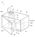
- the multi-cylinder reformer 12, the pre-pressurization water separation unit 30, the post-pressurization water separation unit 32, and the combustion exhaust gas water separation unit 34 are arranged on the back surface portion 56B side.
- the post-pressurization water separation unit 32 and the combustion exhaust gas water separation unit 34 are shown together.
- the hydrogen purifier 16 and the compressor 14 are arranged closer to the front face 56A than the multi-cylinder reformer 12, the pre-pressurization water separation unit 30, the post-pressurization water separation unit 32, and the combustion exhaust gas water separation unit 34. Note that, in FIG. 3, the other devices are not shown.
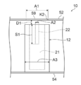
- the distance D1 between the upper portion of the multi-tubular reformer 12 and the top surface portion 52 is shorter than the length S1 of the burner 22 in the longitudinal direction.
- the reformed gas that has passed through the CO conversion catalyst layer 26 is supplied to the CO selective oxidation catalyst layer 27 together with the oxidizing gas (air) supplied from the oxidant gas supply pipe P2B, and carbon monoxide reacts with oxygen on the catalyst. Are converted to carbon dioxide and carbon monoxide is removed.
- the reformed gas in which carbon monoxide is reduced in the CO selective oxidation catalyst layer 27 is sent to the reformed gas discharge pipe P3.
- the hydrogen production device 10 is operated according to the demand for hydrogen.
- city gas and reforming water are supplied to the multi-cylinder reformer 12 from the raw material supply pipe P1 and the reforming water supply pipe P9.
- the city gas and the reforming water are heated while being mixed, and steam reformed in the reforming catalyst layer to generate reformed gas containing hydrogen as a main component.
- Carbon monoxide is removed from the reformed gas at the CO reduction unit, and the reformed gas is sent to the reformed gas discharge pipe P3.
- the reformed gas is supplied to the pre-pressurization water separation unit 30 via the heat exchanger H1 provided in the reformed gas discharge pipe P3.
- the water vapor contained in the reformed gas is condensed by cooling in the heat exchanger H1 and separated from the reformed gas, and sent to the water tank 40 via the reformed gas water pipe P8A.
- the reformed gas from which the water has been separated flows through the communication flow path pipe P4, is supplied to the compressor 14, and is compressed by the compressor 14.
- the compressed reformed gas flows through the flow path pipe P6, passes through the heat exchanger H2, and is supplied to the water separation unit 32 after being pressurized.
- the water vapor contained in the reformed gas is condensed by cooling in the heat exchanger H2, separated from the reformed gas, and sent to the water tank 40 via the reformed gas water pipe P8B.
- the reformed gas from which water has been separated flows through the flow path pipe P6 and is supplied to the hydrogen purifier 16.
- the opening/closing door 58 is opened and the work is performed.
- the hydrogen purifier 16 and the compressor 14 are arranged on the front face 56A side and are easily accessible from the maintenance/inspection port K1. Therefore, the hydrogen purifier 16 and the compressor 14, which are more frequently maintained than the multiple cylinder reformer 12, the pre-pressurization water separation unit 30, the post-pressurization water separation unit 32, and the combustion exhaust gas water separation unit 34, can be easily installed. It can be accessed and the workability of maintenance and inspection can be improved.
- the opening/closing lid 59 is opened and the burner 22 is connected to the combustion section 21 of the multi-tubular reformer 12. From above and taken out of the housing 50. As described above, since the burner 22 can be taken out while the multi-cylinder reformer 12 is arranged in the housing 50, the workability of maintenance and inspection of the burner can be improved.
- the burner 22 can be moved directly above the combustion section 21 and easily taken out from the upper opening K2.
- the distance D1 between the top surface portion 52 of the housing 50 and the upper surface of the multi-cylinder reformer 12 is shorter than the length S1 of the burner 22 in the longitudinal direction, so that the hydrogen production apparatus 10 can be made compact. be able to.
- the openable/closable lid 59 can be closed to protect the inside of the housing 50 except during maintenance and inspection.
Landscapes
- Chemical & Material Sciences (AREA)
- Organic Chemistry (AREA)
- Chemical Kinetics & Catalysis (AREA)
- Engineering & Computer Science (AREA)
- Combustion & Propulsion (AREA)
- Inorganic Chemistry (AREA)
- Health & Medical Sciences (AREA)
- General Health & Medical Sciences (AREA)
- Hydrogen, Water And Hydrids (AREA)
- Fuel Cell (AREA)
Abstract
Dispositif de production d'hydrogène pourvu : d'un modificateur qui a une unité de modification de forme cylindrique multiple et ayant un catalyseur de modification pour modifier une matière première en un gaz modifié contenant du gaz hydrogène, et un brûleur qui est disposé dans un espace de combustion formé à l'intérieur d'un cylindre de manière à pouvoir être inséré dans une ouverture d'une partie cylindrique ou être extractible à partir de celle-ci et chauffe l'unité de modification; d'un purificateur d'hydrogène qui purifie le gaz modifié pour délivrer de l'hydrogène gazeux; et un boîtier qui reçoit le modificateur et le purificateur d'hydrogène et a, sur sa surface supérieure, une ouverture supérieure à partir de laquelle le brûleur peut être extrait.
Applications Claiming Priority (2)
| Application Number | Priority Date | Filing Date | Title |
|---|---|---|---|
| JP2018-231905 | 2018-12-11 | ||
| JP2018231905A JP6505938B1 (ja) | 2018-12-11 | 2018-12-11 | 水素製造装置 |
Publications (1)
| Publication Number | Publication Date |
|---|---|
| WO2020121625A1 true WO2020121625A1 (fr) | 2020-06-18 |
Family
ID=66324195
Family Applications (1)
| Application Number | Title | Priority Date | Filing Date |
|---|---|---|---|
| PCT/JP2019/038489 Ceased WO2020121625A1 (fr) | 2018-12-11 | 2019-09-30 | Dispositif de production d'hydrogène |
Country Status (2)
| Country | Link |
|---|---|
| JP (1) | JP6505938B1 (fr) |
| WO (1) | WO2020121625A1 (fr) |
Families Citing this family (1)
| Publication number | Priority date | Publication date | Assignee | Title |
|---|---|---|---|---|
| EP4158409A1 (fr) | 2020-05-29 | 2023-04-05 | Ricoh Company, Ltd. | Dispositif optique |
Citations (6)
| Publication number | Priority date | Publication date | Assignee | Title |
|---|---|---|---|---|
| US5934897A (en) * | 1996-11-07 | 1999-08-10 | Metallgesellschaft Aktiengesellschaft | Reactor for the autothermal conversion of hydrocarbons |
| JP2003165709A (ja) * | 2001-11-29 | 2003-06-10 | Toho Gas Co Ltd | 水素製造装置 |
| JP2007031185A (ja) * | 2005-07-25 | 2007-02-08 | Fuji Electric Holdings Co Ltd | 燃料改質装置 |
| JP2008235102A (ja) * | 2007-03-22 | 2008-10-02 | Honda Motor Co Ltd | 燃料電池システム |
| WO2011067930A1 (fr) * | 2009-12-03 | 2011-06-09 | パナソニック株式会社 | Système de pile à combustible et procédé de maintenance d'un système de pile à combustible |
| KR101895927B1 (ko) * | 2017-03-10 | 2018-09-10 | (주)신넥앤테크 | 고분자 전해질 연료전지의 연료 개질장치 |
-
2018
- 2018-12-11 JP JP2018231905A patent/JP6505938B1/ja active Active
-
2019
- 2019-09-30 WO PCT/JP2019/038489 patent/WO2020121625A1/fr not_active Ceased
Patent Citations (6)
| Publication number | Priority date | Publication date | Assignee | Title |
|---|---|---|---|---|
| US5934897A (en) * | 1996-11-07 | 1999-08-10 | Metallgesellschaft Aktiengesellschaft | Reactor for the autothermal conversion of hydrocarbons |
| JP2003165709A (ja) * | 2001-11-29 | 2003-06-10 | Toho Gas Co Ltd | 水素製造装置 |
| JP2007031185A (ja) * | 2005-07-25 | 2007-02-08 | Fuji Electric Holdings Co Ltd | 燃料改質装置 |
| JP2008235102A (ja) * | 2007-03-22 | 2008-10-02 | Honda Motor Co Ltd | 燃料電池システム |
| WO2011067930A1 (fr) * | 2009-12-03 | 2011-06-09 | パナソニック株式会社 | Système de pile à combustible et procédé de maintenance d'un système de pile à combustible |
| KR101895927B1 (ko) * | 2017-03-10 | 2018-09-10 | (주)신넥앤테크 | 고분자 전해질 연료전지의 연료 개질장치 |
Also Published As
| Publication number | Publication date |
|---|---|
| JP2020093949A (ja) | 2020-06-18 |
| JP6505938B1 (ja) | 2019-04-24 |
Similar Documents
| Publication | Publication Date | Title |
|---|---|---|
| KR20230029615A (ko) | 수소 생성 방법 | |
| US20100166645A1 (en) | Compact pressure swing reformer | |
| CA2930902C (fr) | Procede de production d'hydrogene | |
| EP3720813B1 (fr) | Système et procédé pour la production de gaz de synthèse | |
| CN101400601A (zh) | 氢制备装置及氢制备方法 | |
| US20050188616A1 (en) | Fuel processing treatment system and fuel processing systems containing the same | |
| WO2020121625A1 (fr) | Dispositif de production d'hydrogène | |
| JP6530123B1 (ja) | 水素製造装置 | |
| KR101472767B1 (ko) | 일산화탄소 가스 발생 장치 및 방법 | |
| KR20230059796A (ko) | 열 교환 개질기의 하류에 전기 스팀 개질기를 포함하는 플랜트에서 합성 가스의 제조 | |
| JP2004017701A (ja) | 水素ステーション及び改質器 | |
| JP6983086B2 (ja) | 水素製造装置 | |
| JP2020079174A (ja) | 水素製造装置 | |
| CA3088018C (fr) | Systeme et procede de vapeur separe dans une installation de production d`hydrogene | |
| JP6602941B1 (ja) | 水素製造装置及び水素製造方法 | |
| JP6924596B2 (ja) | 水素製造装置 | |
| JP2018162195A (ja) | 水素製造装置 | |
| JP7527236B2 (ja) | 改質処理装置 | |
| JP2020079171A (ja) | 水素製造装置、及び水素製造システム | |
| EP0385857B1 (fr) | Procédé et installation de production de monoxyde de carbone | |
| WO2020100463A1 (fr) | Appareil de production d'hydrogene | |
| WO2020100462A1 (fr) | Reformeur de type cylindrique multiple et appareil de production d'hydrogène | |
| JP2020079170A (ja) | 水素製造システム | |
| CN102807199B (zh) | 氩气的提纯方法及提纯装置 | |
| JP2020111488A (ja) | 水素製造システムの配置構造 |
Legal Events
| Date | Code | Title | Description |
|---|---|---|---|
| 121 | Ep: the epo has been informed by wipo that ep was designated in this application |
Ref document number: 19896200 Country of ref document: EP Kind code of ref document: A1 |
|
| NENP | Non-entry into the national phase |
Ref country code: DE |
|
| 122 | Ep: pct application non-entry in european phase |
Ref document number: 19896200 Country of ref document: EP Kind code of ref document: A1 |