WO2020121631A1 - 静電霧化塗装機 - Google Patents
静電霧化塗装機 Download PDFInfo
- Publication number
- WO2020121631A1 WO2020121631A1 PCT/JP2019/039372 JP2019039372W WO2020121631A1 WO 2020121631 A1 WO2020121631 A1 WO 2020121631A1 JP 2019039372 W JP2019039372 W JP 2019039372W WO 2020121631 A1 WO2020121631 A1 WO 2020121631A1
- Authority
- WO
- WIPO (PCT)
- Prior art keywords
- paint
- branch
- nozzle head
- valve body
- circumferential groove
- Prior art date
- Legal status (The legal status is an assumption and is not a legal conclusion. Google has not performed a legal analysis and makes no representation as to the accuracy of the status listed.)
- Ceased
Links
Images


Classifications
-
- B—PERFORMING OPERATIONS; TRANSPORTING
- B05—SPRAYING OR ATOMISING IN GENERAL; APPLYING FLUENT MATERIALS TO SURFACES, IN GENERAL
- B05B—SPRAYING APPARATUS; ATOMISING APPARATUS; NOZZLES
- B05B5/00—Electrostatic spraying apparatus; Spraying apparatus with means for charging the spray electrically; Apparatus for spraying liquids or other fluent materials by other electric means
- B05B5/025—Discharge apparatus, e.g. electrostatic spray guns
-
- B—PERFORMING OPERATIONS; TRANSPORTING
- B05—SPRAYING OR ATOMISING IN GENERAL; APPLYING FLUENT MATERIALS TO SURFACES, IN GENERAL
- B05B—SPRAYING APPARATUS; ATOMISING APPARATUS; NOZZLES
- B05B1/00—Nozzles, spray heads or other outlets, with or without auxiliary devices such as valves, heating means
- B05B1/14—Nozzles, spray heads or other outlets, with or without auxiliary devices such as valves, heating means with multiple outlet openings; with strainers in or outside the outlet opening
-
- B—PERFORMING OPERATIONS; TRANSPORTING
- B05—SPRAYING OR ATOMISING IN GENERAL; APPLYING FLUENT MATERIALS TO SURFACES, IN GENERAL
- B05B—SPRAYING APPARATUS; ATOMISING APPARATUS; NOZZLES
- B05B1/00—Nozzles, spray heads or other outlets, with or without auxiliary devices such as valves, heating means
- B05B1/30—Nozzles, spray heads or other outlets, with or without auxiliary devices such as valves, heating means designed to control volume of flow, e.g. with adjustable passages
- B05B1/3026—Gate valves; Sliding valves; Cocks
-
- B—PERFORMING OPERATIONS; TRANSPORTING
- B05—SPRAYING OR ATOMISING IN GENERAL; APPLYING FLUENT MATERIALS TO SURFACES, IN GENERAL
- B05B—SPRAYING APPARATUS; ATOMISING APPARATUS; NOZZLES
- B05B1/00—Nozzles, spray heads or other outlets, with or without auxiliary devices such as valves, heating means
- B05B1/30—Nozzles, spray heads or other outlets, with or without auxiliary devices such as valves, heating means designed to control volume of flow, e.g. with adjustable passages
- B05B1/3033—Nozzles, spray heads or other outlets, with or without auxiliary devices such as valves, heating means designed to control volume of flow, e.g. with adjustable passages the control being effected by relative coaxial longitudinal movement of the controlling element and the spray head
- B05B1/304—Nozzles, spray heads or other outlets, with or without auxiliary devices such as valves, heating means designed to control volume of flow, e.g. with adjustable passages the control being effected by relative coaxial longitudinal movement of the controlling element and the spray head the controlling element being a lift valve
- B05B1/3046—Nozzles, spray heads or other outlets, with or without auxiliary devices such as valves, heating means designed to control volume of flow, e.g. with adjustable passages the control being effected by relative coaxial longitudinal movement of the controlling element and the spray head the controlling element being a lift valve the valve element, e.g. a needle, co-operating with a valve seat located downstream of the valve element and its actuating means, generally in the proximity of the outlet orifice
- B05B1/306—Nozzles, spray heads or other outlets, with or without auxiliary devices such as valves, heating means designed to control volume of flow, e.g. with adjustable passages the control being effected by relative coaxial longitudinal movement of the controlling element and the spray head the controlling element being a lift valve the valve element, e.g. a needle, co-operating with a valve seat located downstream of the valve element and its actuating means, generally in the proximity of the outlet orifice the actuating means being a fluid
-
- B—PERFORMING OPERATIONS; TRANSPORTING
- B05—SPRAYING OR ATOMISING IN GENERAL; APPLYING FLUENT MATERIALS TO SURFACES, IN GENERAL
- B05B—SPRAYING APPARATUS; ATOMISING APPARATUS; NOZZLES
- B05B1/00—Nozzles, spray heads or other outlets, with or without auxiliary devices such as valves, heating means
- B05B1/30—Nozzles, spray heads or other outlets, with or without auxiliary devices such as valves, heating means designed to control volume of flow, e.g. with adjustable passages
- B05B1/3033—Nozzles, spray heads or other outlets, with or without auxiliary devices such as valves, heating means designed to control volume of flow, e.g. with adjustable passages the control being effected by relative coaxial longitudinal movement of the controlling element and the spray head
- B05B1/3086—Nozzles, spray heads or other outlets, with or without auxiliary devices such as valves, heating means designed to control volume of flow, e.g. with adjustable passages the control being effected by relative coaxial longitudinal movement of the controlling element and the spray head the controlling element being a grooved body, which is movable in the outlet orifice
-
- B—PERFORMING OPERATIONS; TRANSPORTING
- B05—SPRAYING OR ATOMISING IN GENERAL; APPLYING FLUENT MATERIALS TO SURFACES, IN GENERAL
- B05B—SPRAYING APPARATUS; ATOMISING APPARATUS; NOZZLES
- B05B5/00—Electrostatic spraying apparatus; Spraying apparatus with means for charging the spray electrically; Apparatus for spraying liquids or other fluent materials by other electric means
- B05B5/025—Discharge apparatus, e.g. electrostatic spray guns
- B05B5/035—Discharge apparatus, e.g. electrostatic spray guns characterised by gasless spraying, e.g. electrostatically assisted airless spraying
-
- B—PERFORMING OPERATIONS; TRANSPORTING
- B05—SPRAYING OR ATOMISING IN GENERAL; APPLYING FLUENT MATERIALS TO SURFACES, IN GENERAL
- B05B—SPRAYING APPARATUS; ATOMISING APPARATUS; NOZZLES
- B05B5/00—Electrostatic spraying apparatus; Spraying apparatus with means for charging the spray electrically; Apparatus for spraying liquids or other fluent materials by other electric means
- B05B5/16—Arrangements for supplying liquids or other fluent material
-
- B—PERFORMING OPERATIONS; TRANSPORTING
- B05—SPRAYING OR ATOMISING IN GENERAL; APPLYING FLUENT MATERIALS TO SURFACES, IN GENERAL
- B05B—SPRAYING APPARATUS; ATOMISING APPARATUS; NOZZLES
- B05B15/00—Details of spraying plant or spraying apparatus not otherwise provided for; Accessories
- B05B15/50—Arrangements for cleaning; Arrangements for preventing deposits, drying-out or blockage; Arrangements for detecting improper discharge caused by the presence of foreign matter
- B05B15/58—Arrangements for cleaning; Arrangements for preventing deposits, drying-out or blockage; Arrangements for detecting improper discharge caused by the presence of foreign matter preventing deposits, drying-out or blockage by recirculating the fluid to be sprayed from upstream of the discharge opening back to the supplying means
-
- B—PERFORMING OPERATIONS; TRANSPORTING
- B05—SPRAYING OR ATOMISING IN GENERAL; APPLYING FLUENT MATERIALS TO SURFACES, IN GENERAL
- B05B—SPRAYING APPARATUS; ATOMISING APPARATUS; NOZZLES
- B05B5/00—Electrostatic spraying apparatus; Spraying apparatus with means for charging the spray electrically; Apparatus for spraying liquids or other fluent materials by other electric means
- B05B5/025—Discharge apparatus, e.g. electrostatic spray guns
- B05B5/043—Discharge apparatus, e.g. electrostatic spray guns using induction-charging
-
- B—PERFORMING OPERATIONS; TRANSPORTING
- B05—SPRAYING OR ATOMISING IN GENERAL; APPLYING FLUENT MATERIALS TO SURFACES, IN GENERAL
- B05B—SPRAYING APPARATUS; ATOMISING APPARATUS; NOZZLES
- B05B7/00—Spraying apparatus for discharge of liquids or other fluent materials from two or more sources, e.g. of liquid and air, of powder and gas
- B05B7/02—Spray pistols; Apparatus for discharge
- B05B7/08—Spray pistols; Apparatus for discharge with separate outlet orifices, e.g. to form parallel jets, i.e. the axis of the jets being parallel, to form intersecting jets, i.e. the axis of the jets converging but not necessarily intersecting at a point
- B05B7/0892—Spray pistols; Apparatus for discharge with separate outlet orifices, e.g. to form parallel jets, i.e. the axis of the jets being parallel, to form intersecting jets, i.e. the axis of the jets converging but not necessarily intersecting at a point the outlet orifices for jets constituted by a liquid or a mixture containing a liquid being disposed on a circle
Definitions
- the present invention relates to an electrostatic atomization coating machine, and more specifically, a nozzle head is provided with a plurality of paint ejection ports, a paint chamber is provided inside the nozzle head, and a paint supply passage is provided in the paint chamber.
- the paint is supplied, each of the paint jets communicates with the paint chamber through a separate branch paint passage, and a voltage applying device that applies a potential difference between the nozzle head and the object to be coated is provided,
- the paint sprayed from each of the paint jets through the supply passage, the paint chamber, and the branch paint passage relates to an electrostatic atomizing coater that is charged by voltage application by the voltage applying device.
- the paint in a charged state ejected from a plurality of paint ejection ports is atomized by the action of an electric field formed around each paint ejection port, and thus is atomized.
- the charged electrified paint is electrostatically attracted to the object to be coated by the potential difference between the object to be coated and the nozzle head and flies to the surface of the object to be coated.
- the main problem of the present invention is to effectively solve the above problems by rational improvement.
- the first characteristic configuration of the present invention relates to an electrostatic atomization coating machine, and the characteristic features thereof are:
- the nozzle head has multiple paint outlets, A paint chamber is provided inside the nozzle head, and paint is supplied to the paint chamber through a paint supply passage, Each of the paint outlets communicates with the paint chamber through a separate branch paint passage, A voltage applying device for providing a potential difference between the nozzle head and the object to be coated is provided, The paint sprayed from each of the paint outlets through the paint supply passage, the paint chamber, and the branch paint passage is an electrostatic atomizing coater that is charged by voltage application by the voltage applying device.
- An on-off valve device is provided which opens and closes all the branch paint passages, or opens and closes a plurality of specific branch paint passages of all the branch paint passages.
- the on-off valve device when an on-off valve device that opens and closes all the branch paint passages is provided as the on-off valve device, the on-off valve device is closed and all the branch paint passages are closed when the painting work is interrupted or ended. Therefore, regardless of the attitude of the nozzle header at that time, external air may enter the paint chamber through some paint jets, and the paint remaining in the paint chamber may cause some other paint to flow into the paint chamber when the air enters. It can be reliably prevented from leaking to the outside through the ejection port.
- an on-off valve device that opens and closes a specific part of a plurality of branch paint passages out of all branch paint passages is provided as an on-off valve device
- air intrusion and paint leakage may occur in all paint outlets.
- Specific multiple paint branch passages corresponding to multiple paint jets with high performance If some of the branch paint passages are selected and an on-off valve device is installed, it is possible to By closing the on-off valve device and closing a certain part of the multiple branch paint passages, external air can pass through some paint outlets and paint chambers regardless of the posture of the nozzle header at that time, as described above. It is possible to reliably prevent the residual paint in the paint chamber from leaking to the outside through another part of the paint ejection port due to the air invasion.
- a second characteristic configuration of the present invention specifies an embodiment suitable for carrying out the first characteristic configuration, and the characteristic thereof is:
- the paint ejection ports are arranged in a state in which they are arranged in a line at equal intervals in the circumferential direction on the same circumference of the tip end surface portion of the nozzle head.
- each paint An electric field is uniformly formed around the ejection port without bias.
- the atomized paint sprayed from a plurality of paint jets becomes more uniform, which improves the coating quality of the coated object.
- a third characteristic configuration of the present invention specifies an embodiment suitable for carrying out the second characteristic configuration, and the characteristic thereof is:
- a plurality of paint ejection nozzles each having the paint ejection port are individually arranged on the tip end surface portion of the nozzle head in a protruding state and arranged in a line at equal intervals in the circumferential direction on the same circumference. There is a point.
- each paint ejection nozzle since each paint ejection nozzle is in the protruding state, it is possible to more effectively form an electric field around each paint ejection port, and thus, the charged state ejected from each paint ejection port is increased. It is possible to promote the atomization of the coating composition and further improve the coating quality of the coated object.
- a fourth characteristic configuration of the present invention specifies an embodiment suitable for carrying out the second characteristic configuration, and the characteristic thereof is:
- An annular protrusion is provided on the tip surface of the nozzle head,
- the coating material ejection ports are arranged in the annular protruding portion so as to be aligned in a line at equal intervals in the circumferential direction of the annular protruding portion.
- each paint ejection port since the annular projecting portion in which each paint ejection port is formed is in a protruding state, the paint ejection port can be effectively formed while the electric field is effectively formed around each paint ejection port.
- the structure and shape of the tip surface of the nozzle head can be simplified, compared with the case where a plurality of paint ejection nozzles provided individually are arranged side by side on the tip surface of the nozzle head in an independently protruding state. Can be easily manufactured.
- a fifth characteristic configuration of the present invention specifies an embodiment suitable for carrying out the second characteristic configuration, and the characteristic thereof is:
- the paint ejection ports are arranged so as to be arranged in a line at equal intervals in the circumferential direction on each of a plurality of concentric circles on the tip end surface portion of the nozzle head.
- a sixth characteristic configuration of the present invention specifies an embodiment suitable for carrying out any of the first to fifth characteristic configurations, and its characteristic is
- the on-off valve device includes one common valve body housed in the paint chamber, The common valve body is opened and closed between a valve closed position that simultaneously closes the inlets of the branch paint passages that open to the paint chamber and a valve open position that simultaneously opens the inlets of the branch paint passages. ..
- the structure of the head can be simplified, which facilitates the manufacture of the device, reduces the cost of the device, and also enables the weight and size of the nozzle head to be reduced.
- a seventh characteristic configuration of the present invention specifies an embodiment suitable for carrying out the sixth characteristic configuration, and the characteristic thereof is: Inside the nozzle head, a circumferential groove is formed as the paint chamber, The inlet of the branch paint passage is arranged in a state in which it is arranged at equal intervals in the circumferential direction of the circumferential groove portion on the bottom surface of the circumferential groove portion,
- the common valve body has an annular shape that fits into the circumferential groove portion, The common valve body is located at a point of moving inside the circumferential groove portion like a piston in a perspective direction with respect to a bottom surface of the circumferential groove portion as an opening/closing operation between the valve closing position and the valve opening position.
- An eighth characteristic configuration of the present invention specifies an embodiment suitable for implementing the seventh characteristic configuration, and the characteristic thereof is: A communication groove that communicates from one end surface side to the other end surface side of the common valve body in the annular shape is formed on the inner peripheral surface or the outer peripheral surface of the common valve body in the annular shape.
- the common valve body fitted in the circumferential groove portion when the annular common valve body fitted in the circumferential groove portion is piston-operated in the circumferential groove portion toward and away from the bottom surface of the circumferential groove portion, the common valve is passed through the communication groove.
- the paint can be driven back and forth between the one end face side and the other end face side of the body (that is, between the bottom side region and the anti-bottom side region of the circumferential groove portion), whereby the common valve body It is possible to smooth the piston-like opening/closing operation.
- a ninth characteristic configuration of the present invention specifies an embodiment suitable for carrying out the sixth characteristic configuration, and the characteristic is Inside the nozzle head, a circumferential groove is formed as the paint chamber, The inlet of the branch paint passage is arranged in a state in which it is arranged at equal intervals in the circumferential direction of the circumferential groove portion on the bottom surface of the circumferential groove portion,
- the common valve body has an annular shape that fits into the circumferential groove portion,
- the common valve body is formed with a plurality of communication holes penetrating from one end surface side to the other end surface side in the annular shape of the common valve body, The communication holes are arranged individually corresponding to the inlets of the branch paint paths, respectively, and are arranged in a state in which they are arranged at equal intervals in the circumferential direction in the annular shape of the common valve body,
- the common valve body is configured to rotate inside the circumferential groove portion in a circumferential direction of the circumferential groove portion as an opening/closing operation between the
- the annular common valve body fitted in the circumferential groove portion is rotated in the circumferential direction of the circumferential groove portion inside the circumferential groove portion so that the inlets of the branch paint passages are of the common valve body.
- the branch paint passages are brought into communication with each other, the inlets of the branch paint passages are communicated with the circumferential groove portions as the paint chambers through the communication holes to open the branch paint passages.
- annular common valve element is rotated in the circumferential direction of the circumferential groove portion inside the circumferential groove portion until each communication hole of the common valve element is disengaged from the inlet of each branch paint passage, and the branch coating material is rotated.
- the branch paint passages are closed by closing the inlets of the respective passages with a common valve body.
- the annular common valve element is used as the circumferential groove portion. Since it is only necessary to rotate in the circumferential direction of the circumferential groove portion inside, the space required for the opening/closing operation of the common valve body between the valve closing position and the valve opening position can be reduced, and the nozzle head The size can be further reduced.
- a tenth characteristic configuration of the present invention specifies an embodiment suitable for carrying out the first or second characteristic configuration, and the characteristic is
- Each of the branch paint passages is equipped with an individual on-off valve as the on-off valve device, A common operation means for opening and closing the on-off valves at the same time is provided.
- branch paint passages are simultaneously opened and closed by simultaneously opening and closing the on-off valves equipped in each of the branch paint passages by the common operation means.
- each branch paint passage is equipped with an individual opening/closing valve, compared to simultaneously opening and closing a plurality of branch paint passages by one common valve body, each branch paint passage in the nozzle head is opened.
- the degree of freedom in arranging the nozzles is increased, which facilitates the design of the nozzle head.
- An eleventh characteristic configuration of the present invention specifies an embodiment suitable for carrying out any of the first to tenth characteristic configurations, and the characteristic is
- the nozzle head is formed of an electrically insulating material or a weakly conductive material.
- the electric field formed around each paint jet can be strengthened accordingly, and atomization of the charged paint jetted from the paint jet can be further promoted.
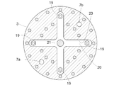
- FIG. 1 is a vertical sectional view of an electrostatic atomization coating machine.
- FIG. 2 is a front view of the tip end surface of the nozzle head.
- FIG. 3 is a view taken along the line III-III in FIG. 4 is a sectional view taken along line IV-IV in FIG.
- FIG. 5 is a perspective view of the common valve body.
- FIG. 6 is a front view of a tip end surface portion of a nozzle head showing another embodiment.
- FIG. 7 is a structural diagram of an on-off valve device showing another embodiment.
- FIG. 8 is a front view of a nozzle head tip surface portion showing another embodiment.
- FIG. 9 is a schematic vertical sectional view of a nozzle head showing another embodiment.
- FIG. 1 shows an electrostatic atomization coating machine 1 for coating an object by paint spraying.
- the electrostatic atomization coating machine 1 includes a main body 2 connected to the tip of a working arm of a coating robot, and a main body 2 thereof.
- the nozzle head 3 is attached to the tip of the main body 2.
- the coating work using the electrostatic atomization coating machine 1 proceeds while sequentially moving the target portion of the paint spray on the object to be coated, but at this time, between the object to be coated and the nozzle head 3.
- the distance and the distance between the nozzles 3 are kept constant, and the position and orientation of the electrostatic atomizer coating machine 1 is maintained so that the tip end surface of the nozzle head 3 faces the object to be coated vertically.
- the operation is sequentially adjusted.
- a paint chamber 4 is formed inside the nozzle head 3, and the paint chamber 4 is arranged concentrically with the cylindrical nozzle head 3. Further, an on-off valve device 5 is installed inside the nozzle head 3.
- a paint supply passage 7a and a paint return passage 7b are formed extending to the paint chamber 4 inside the nozzle head 3, and a supply side switching valve 6A for opening and closing the paint supply passage 7a, and A return-side switching valve 6B for opening and closing the paint return passage 7b is provided.
- annular projecting portion 11 arranged concentrically with the nozzle head 3 is formed on the tip end surface portion of the nozzle head 3 which is directly opposed to the object to be coated.
- a large number of paint jets 12a are formed on the annular projection 11, and the large number of paint jets 12a are arranged in a line at equal intervals in the circumferential direction of the annular projection 11. There is.
- a plurality of paint ejection nozzles N each having a paint ejection port 12a are individually provided. In a protruding state, they may be arranged in a line at equal intervals in the circumferential direction on the same circumference.
- Each paint outlet 12a communicates with the paint chamber 4 through an individual branch paint passage 13, and the paint T supplied to the paint chamber 4 through the paint supply passage 7a passes through each branch paint passage 13 and each paint outlet 12a. Erupted from.
- the paint T is in a state of flowing through the paint supply passage 7a, the paint chamber 4, and the paint return passage 7b.
- the parts are sent from the paint chamber 4 to each paint jet 12a through each branch paint passage 13.
- the electrostatic atomization coating machine 1 is equipped with a voltage application device 14 that applies a potential difference ⁇ V between the object to be coated and the nozzle head 3, and the paint supply passage 7a, the paint chamber 4, and the The paint T ejected from each paint ejection port 12 a via the branch paint passage 13 is charged by the high voltage applied by the voltage application device 14.
- an electric field is formed around each paint ejection port 12a by applying a high voltage by the voltage application device 14, and the charged paint T ejected from each paint ejection port 12a is a so-called electrostatic spray.
- the atomized paint T which is atomized by the action of the electric field formed around the ejection port 12a, is electrostatically attracted to the object to be coated by the potential difference between the nozzle head 3 and the object to be coated. It flies and is applied to the surface of the object to be coated.
- the on-off valve device 5 mounted on the nozzle head 3 is a valve device that opens and closes the branch paint passage 13 with respect to the paint ejection port 12a, and this on-off valve device 5 is constantly urged toward the valve opening side by a spring 18.
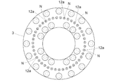
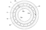
- the paint chamber 4 inside the nozzle head 3 is provided with a circumferential groove portion 15 which is concentric with the annular protrusion 11 and has substantially the same diameter, and a large number of paint branches are provided.
- the inlets 13a of each of the passages 13 open in the circumferential groove portion 15 as the paint chamber 4 on the bottom surface of the circumferential groove portion 15, and these many inlets 13a correspond to the circular row of the paint outlets 12a.
- the circumferential groove portions 15 are arranged in a line at equal intervals in the circumferential direction.
- valve element 16 of the on-off valve device 5 is formed in an annular shape that fits in the circumferential groove portion 15, and is housed in the circumferential groove portion 15 in a fitted state.
- the valve body 16 is a common valve body for many branch paint passages 13.
- the annular common valve element 16 moves to the bottom surface side of the circumferential groove portion 15 in a piston shape, and the inlets 13a of all the branch paint passages 13 have the annular common valve.
- the annular common valve body 16 moves in a piston shape to the side away from the bottom surface of the circumferential groove portion 15, so that all By opening the inlet 13a of the branch paint passage 13, all the branch paint passages 13 are simultaneously opened.
- the paint supply passage 7a and the paint return passage 7b are closed in the supply side switching valve 6A and the return side switching valve 6B.
- outside air may enter the paint chamber 4 through the branch paint passage 13 from some of the paint outlets 12a located at the upper part of the plurality of paint outlets 12a. Accordingly, the paint T remaining in the paint chamber 4 may leak to the outside through the branch paint passage 13 and from some other paint outlets 12a located in the lower portion.
- the opening/closing valve device 5 when stopping the spraying of the paint on the object to be coated, the opening/closing valve device 5 is operated to close so that all the branch paint passages 13 are annular common valve bodies. 16 by this, regardless of the posture of the nozzle head 3 at that time, the external air enters through the paint outlets 12a and the other paint outlets 12a as described above. External leakage of the residual paint T is reliably prevented.
- each communication groove 17 has a common annular shape.
- the valve body 16 is formed from one end surface to the other end surface thereof, and at the one end surface of the common valve body 16, each communication groove 17 is opened to a region on the bottom surface side of the circumferential groove portion 15, and at the other end surface of the common valve body 16, Each communication groove 17 is open to the region of the circumferential groove portion 15 on the side opposite to the bottom surface.
- the paint T supplied to the paint chamber 4 is transferred from the area on the side opposite to the bottom surface to the area on the bottom surface side in the circumferential groove portion 15 through the plurality of communication grooves 17.
- the paint T passes between the region on the bottom surface side and the region on the anti-bottom surface side of the circumferential groove portion 15 through the large number of communication grooves 17.
- the annular common valve body 16 is connected to the cross-shaped support member 20 via four connecting rods 19, and the four connecting rods 19 are arranged at equal intervals in the circumferential direction of the circumferential groove portion 15. It is arranged.
- the cross-shaped support member 20 is connected to the valve operating piston 22 via the valve operating shaft 21 arranged on the central axis q of the nozzle head 3.
- a guide hole 23 for the cross-shaped support member 20 is formed inside the nozzle head 3, and the guide hole 23 is formed in a cross shape when viewed from the direction of the central axis q of the nozzle head. Has been done.
- the cross-shaped support member 20 reciprocates inside the guide hole 23 having this cross shape in the direction of the central axis q of the nozzle head.
- the nozzle head 3 is formed of a non-conductive material or a weakly conductive material, which may cause the nozzle head 3 in a state where a high voltage is applied by the voltage applying device 14 to unexpectedly approach another object. Also, the occurrence of discharge between the nozzle head 3 and another object is prevented.
- the opening/closing valve device 5 has a structure in which the inlets 13a of the branch paint passages 13 are simultaneously opened and closed with respect to the paint chamber 4 by the piston-like opening/closing operation of the annular common valve body 16.
- the structure shown in FIG. 7 may be adopted as the structure of the on-off valve device 5.
- Reference numeral 24 is an arrangement that individually corresponds to the inlets 13a of the branch paint passages 13 that open to the bottom surface of the circumferential groove portion 15, and is arranged in a state of being arranged at equal intervals in the circumferential direction in the annular shape of the common valve body 16. Has been done.
- the annular common valve body 16 is configured to rotate in the circumferential direction inside the circumferential groove portion 15 by rotating around the central axis of the annular shape as an opening/closing operation.
- the common valve body 16 is pivotally operated until the inlets 13a of the respective branch paint passages 13 communicate with the respective communication holes 24 of the common valve body 16, whereby the communication holes 24 are formed.
- the inlets 13a of the respective branch paint passages 13 are opened to the paint chamber 4, whereby the respective branch paint passages 13 are simultaneously opened.
- each branch paint passage 13 is closed at the same time.
- the plurality of paint ejection ports 12a is not limited to being formed on the tip surface portion of the nozzle head 3 in an annular row arrangement, but may be formed on the tip surface portion of the nozzle head 3 in a matrix arrangement.
- each of the opening/closing valves 5v may be equipped with an individual opening/closing valve 5v, and these opening/closing valves 5v may be simultaneously opened/closed by a common operating means.
- the electrostatic atomization coating machine of the present invention can be used for coating various bodies in various fields such as coating of automobile bodies and automobile parts, coating of casings of electric appliances and construction materials.
Landscapes
- Electrostatic Spraying Apparatus (AREA)
- Nozzles (AREA)
Abstract
ノズルヘッド3には複数の塗料噴出口12aが設けられ、ノズルヘッド3の内部には塗料室4が設けられて、塗料室4には塗料供給路7aを通じて塗料Tが供給され、塗料噴出口12aの夫々は、個別の分岐塗料路13を通じて塗料室4に連通し、ノズルヘッド3と被塗物との間に電位差を付与する電圧印加装置14が設けられ、塗料供給路7a、塗料室4並びに分岐塗料路13を通じて塗料噴出口12aの夫々から噴出される塗料Tは、電圧印可装置14による電圧印加により帯電状態になる静電霧化塗装機において、 全ての分岐塗料路13を開閉する、又は、全ての分岐塗料路13のうちの特定一部の複数の分岐塗料路を開閉する開閉弁装置5が設けられる。これにより、ノズルヘッド3内への外部空気の侵入やノズルヘッド3外部への塗料漏出が防止される。
Description
本発明は静電霧化塗装機に関し、詳しくは、ノズルヘッドには複数の塗料噴出口が設けられ、前記ノズルヘッドの内部には塗料室が設けられて、前記塗料室には塗料供給路を通じて塗料が供給され、前記塗料噴出口の夫々は、個別の分岐塗料路を通じて前記塗料室に連通し、前記ノズルヘッドと被塗物との間に電位差を付与する電圧印加装置が設けられ、前記塗料供給路、前記塗料室、並びに前記分岐塗料路を経て前記塗料噴出口の夫々から噴出される塗料は、前記電圧印可装置による電圧印加により帯電状態になる静電霧化塗装機に関する。
この種の静電霧化塗装機(特許文献1参照)では、複数の塗料噴出口から噴出された帯電状態の塗料は、各塗料噴出口の周りに形成される電場の作用により微粒化し、微粒化した帯電状態の塗料が、被塗物とノズルヘッドとの間の電位差により静電的に被塗物に引き付けられて飛翔することで被塗物の表面に塗着する。
また、特許文献1において提案されている静電霧化塗装機では、ノズルヘッドの姿勢(換言すれば、ノズルヘッドの向き)にかかわらず複数の塗料噴出口の夫々から帯電状態の塗料が均一に噴出されることを目的として、ノズルヘッド内の塗料室から各塗料噴出口に至る分岐塗料路の夫々に流路抵抗体が装備され、これにより、各分岐塗料路において塗料は、流路抵抗体の存在により生じる一定の通過抵抗に抗して分岐塗料路を通過する。
ところで従来、この種の静電霧化塗装機では、特許文献1に示されるように分岐塗料路の夫々に流路抵抗体が装備されたとしても、塗装作業の中断や終了のために塗料室への塗料の供給が停止されたとき、そのときのノズルヘッドの姿勢によっては、複数の塗料噴出口のうち上部に位置する一部の塗料噴出口を通じて外部の空気が塗料室に侵入するのに伴い、塗料室に残存していた塗料が下部に位置する他の塗料噴出口を通じて外部へ漏れ出ることがあり、この漏出塗料がノズルヘッドを初め各部に付着することで、清掃メンテナンスの負担が大きくなる問題があった。
また、一部の塗料噴出口を通じて塗料室内に侵入した空気の影響により、複数の塗料噴出口からの次回の塗料噴出が不良になって、被塗物の塗装に不都合を来す問題もあった。
この実情に鑑み、本発明の主たる課題は、合理的な改良により上記問題を効果的に解消する点にある。
本発明の第1特徴構成は、静電霧化塗装機に係り、その特徴は、
ノズルヘッドには複数の塗料噴出口が設けられ、
前記ノズルヘッドの内部には塗料室が設けられて、前記塗料室には塗料供給路を通じて塗料が供給され、
前記塗料噴出口の夫々は、個別の分岐塗料路を通じて前記塗料室に連通し、
前記ノズルヘッドと被塗物との間に電位差を付与する電圧印加装置が設けられ、
前記塗料供給路、前記塗料室、並びに前記分岐塗料路を経て前記塗料噴出口の夫々から噴出される塗料は、前記電圧印可装置による電圧印加により帯電状態になる静電霧化塗装機であって、
全ての前記分岐塗料路を開閉する、又は、全ての前記分岐塗料路のうちの特定一部の複数の前記分岐塗料路を開閉する開閉弁装置が設けられている点にある。
この構成では、開閉弁装置として、全ての分岐塗料路を開閉する開閉弁装置が設けられる場合、塗装作業の中断や終了の際に、開閉弁装置を閉弁させて全ての分岐塗料路を閉じることで、そのときのノズルヘッダの姿勢にかかわらず、外部の空気が一部の塗料噴出口を通じて塗料室に侵入することや、その空気侵入に伴い塗料室における残存塗料が他の一部の塗料噴出口を通じて外部に漏れ出ることを確実に防止できる。
また、開閉弁装置として、全ての分岐塗料路のうちの特定一部の複数の分岐塗料路を開閉する開閉弁装置が設けられる場合、全ての塗料噴出口のうち空気侵入や塗料漏洩の発生可能性が高い複数の塗料噴出口に対応する複数の塗料分岐路を特定一部の複数の分岐塗料路に選定して開閉弁装置を設けておけば、塗装作業の中断や終了の際に、その開閉弁装置を閉弁させて特定一部の複数の分岐塗料路を閉じることで、上記と同様、そのときのノズルヘッダの姿勢にかかわらず、外部の空気が一部の塗料噴出口を通じて塗料室に侵入することや、その空気侵入に伴い塗料室における残存塗料が他の一部の塗料噴出口を通じて外部に漏れ出ることを確実に防止できる。
そして、このように塗料室における残存塗料の外部漏出、及び、塗料室への外部空気の侵入が防止されることで、付着塗料を除去する清掃メンテナンスの負担を効果的に低減でき、また、塗料室に侵入した空気に原因する被塗物塗装上の不都合も効果的に回避できる。
本発明の第2特徴構成は、第1特徴構成の実施に好適な実施形態を特定するものであり、その特徴は、
前記塗料噴出口は、前記ノズルヘッドの先端面部における同一円周上において周方向に等間隔で一列に並ぶ状態に配置されている点にある。
前記塗料噴出口は、前記ノズルヘッドの先端面部における同一円周上において周方向に等間隔で一列に並ぶ状態に配置されている点にある。
この構成によれば、塗料噴出口が等間隔で円周方向に一列に並ぶ状態に配置されていることから、隣り合う塗料噴出口どうしの間で電場の相互干渉が生じるにしても、各塗料噴出口の周りには電場が偏りなく均一に形成される。
したがって、複数の塗料噴出口から噴出された帯電状態の塗料の微粒化が均一になり、これにより、被塗物の塗装品質が向上する。
本発明の第3特徴構成は、第2特徴構成の実施に好適な実施形態を特定するものであり、その特徴は、
前記ノズルヘッドの先端面部には、前記塗料噴出口を個々に備える複数の塗料噴出ノズルが、個々に独立した突出状態で同一円周上において周方向に等間隔に一列に並ぶ状態に配設されている点にある。
前記ノズルヘッドの先端面部には、前記塗料噴出口を個々に備える複数の塗料噴出ノズルが、個々に独立した突出状態で同一円周上において周方向に等間隔に一列に並ぶ状態に配設されている点にある。
この構成によれば、各塗料噴出ノズルが突出状態にあることで、各塗料噴出口の周りに電場を一層効果的に形成することができ、これにより、各塗料噴出口から噴出された帯電状態の塗料の微粒化を促進することができて、被塗物の塗装品質を一層向上させることができる。
本発明の第4特徴構成は、第2特徴構成の実施に好適な実施形態を特定するものであり、その特徴は、
前記ノズルヘッドの先端面部には円環状突出部が設けられ、
前記塗料噴出口は、前記円環状突出部において前記円環状突出部の周方向に等間隔で一列に並ぶ状態に配置されている点にある。
前記ノズルヘッドの先端面部には円環状突出部が設けられ、
前記塗料噴出口は、前記円環状突出部において前記円環状突出部の周方向に等間隔で一列に並ぶ状態に配置されている点にある。
この構成によれば、各塗料噴出口が形成された円環状突出部が突出状態にあることで、各塗料噴出口の周りに電場が効果的に形成されるようにしながらも、塗料噴出口を個々に備える複数の塗料噴出ノズルを個々に独立した突出状態でノズルヘッドの先端面部に並設するのに比べ、ノズルヘッド先端面部の構造・形状を簡単化することができ、これにより、ノズルヘッドの製作を容易にすることができる。
本発明の第5特徴構成は、第2特徴構成の実施に好適な実施形態を特定するものであり、その特徴は、
前記塗料噴出口は、前記ノズルヘッドの先端面部における同芯状の複数の円周上の夫々において、周方向に等間隔で一列に並ぶ状態に配置されている点にある。
前記塗料噴出口は、前記ノズルヘッドの先端面部における同芯状の複数の円周上の夫々において、周方向に等間隔で一列に並ぶ状態に配置されている点にある。
この構成によれば、隣り合う同芯円周どうしの間の間隔(即ち、半径差)さえ十分に確保すれば、各円周上に形成した塗料噴出口の環状列の夫々について、第2特徴構成による作用効果(即ち、噴出帯電塗料の均一な微粒化)を得ることができる。
そして、そのように均一微粒化の効果を得ながらも、同芯状の複数の円周の夫々に塗料噴出口の環状列を形成することで、単位時間当たりの塗料噴出量を大きくすることができ、これにより、このノズルヘッドを用いた塗装作業の能率を高めることができる。
本発明の第6特徴構成は、第1~第5特徴構成のいずれかの実施に好適な実施形態を特定するものであり、その特徴は、
前記開閉弁装置は、前記塗料室に収容された1つの共通弁体を備え、
前記共通弁体は、前記塗料室に開口する前記分岐塗料路夫々の入口を同時に閉塞する閉弁位置と、それら分岐塗料路夫々の入口を同時に開放する開弁位置とにわたって開閉動作する点にある。
前記開閉弁装置は、前記塗料室に収容された1つの共通弁体を備え、
前記共通弁体は、前記塗料室に開口する前記分岐塗料路夫々の入口を同時に閉塞する閉弁位置と、それら分岐塗料路夫々の入口を同時に開放する開弁位置とにわたって開閉動作する点にある。
この構成によれば、全ての分岐塗料路、又は、全ての分岐塗料路のうちの特定一部の複数の分岐塗料路を開閉するのに、1つの共通弁体を設けるだけで済むから、ノズルヘッドの構造を簡素化することができ、これにより、装置の製作を容易にするとともに、装置コストを安価にすることができ、また、ノズルヘッドの軽量化や小型化も可能になる。
本発明の第7特徴構成は、第6特徴構成の実施に好適な実施形態を特定するものであり、その特徴は、
前記ノズルヘッドの内部には、前記塗料室として円周状溝部が形成され、
前記分岐塗料路の入口は、前記円周状溝部の底面において前記円周状溝部の周方向に等間隔に並ぶ状態に配置され、
前記共通弁体は前記円周状溝部に嵌合する円環形状を備え、
前記共通弁体は、前記閉弁位置と前記開弁位置とにわたる開閉動作として、前記円周状溝部の内部を前記円周状溝部の底面に対する遠近方向にピストン状に移動する点にある。
前記ノズルヘッドの内部には、前記塗料室として円周状溝部が形成され、
前記分岐塗料路の入口は、前記円周状溝部の底面において前記円周状溝部の周方向に等間隔に並ぶ状態に配置され、
前記共通弁体は前記円周状溝部に嵌合する円環形状を備え、
前記共通弁体は、前記閉弁位置と前記開弁位置とにわたる開閉動作として、前記円周状溝部の内部を前記円周状溝部の底面に対する遠近方向にピストン状に移動する点にある。
この構成によれば、全ての分岐塗料路、又は、全ての分岐塗料路のうちの特定一部の複数の分岐塗料路を開閉するのに、1つの共通弁体を単にピストン動作させるだけで済むから、開閉弁装置における弁体の駆動構造を簡素にすることができ、これにより、装置の製作を一層容易にするとともに、装置コストも一層安価にすることができる。
本発明の第8特徴構成は、第7特徴構成の実施に好適な実施形態を特定するものであり、その特徴は、
前記共通弁体の前記円環形状における内周面又は外周面には、前記共通弁体の前記円環形状における一端面側から他端面側にわたって連通する連通溝が形成されている点にある。
前記共通弁体の前記円環形状における内周面又は外周面には、前記共通弁体の前記円環形状における一端面側から他端面側にわたって連通する連通溝が形成されている点にある。
この構成によれば、円周状溝部に嵌合させた円環状の共通弁体を円周状溝部の内部において円周状溝部の底面に対する遠近方向にピストン動作させるとき、上記連通溝を通じて共通弁体の一端面側と他端面側との間(即ち、円周状溝部の底側領域と反底側領域との間)で塗料を従動的に行き来させることができ、これにより、共通弁体のピストン状の開閉動作を円滑化することができる。
本発明の第9特徴構成は、第6特徴構成の実施に好適な実施形態を特定するものであり、その特徴は、
前記ノズルヘッドの内部には、前記塗料室として円周状溝部が形成され、
前記分岐塗料路の入口は、前記円周状溝部の底面において前記円周状溝部の周方向に等間隔に並ぶ状態に配置され、
前記共通弁体は前記円周状溝部に嵌合する円環形状を備え、
前記共通弁体には、前記共通弁体の円環形状における一端面側から他端面側にわたって貫通する複数の連通孔が形成され、
前記連通孔は、前記分岐塗料路夫々の入口に対して個別に対応する配置で、前記共通弁体の円環形状における周方向に等間隔に並ぶ状態に配置され、
前記共通弁体は、前記閉弁位置と前記開弁位置とにわたる開閉動作として、前記円周状溝部の内部を前記円周状溝部の周方向に回動する点にある。
この構成では、円周状溝部に嵌合する円環状の共通弁体を円周状溝部の内部で円周状溝部の周方向に回動させて、分岐塗料路夫々の入口が共通弁体の各連通孔と連通する状態にすることで、各連通孔を通じ分岐塗料路夫々の入口を塗料室としての円周状溝部に連通させて、それら分岐塗料路を開く。
また、共通弁体の各連通孔が分岐塗料路夫々の入口から外れる状態まで、円環状の共通弁体を円周状溝部の内部で円周状溝部の周方向に回動させて、分岐塗料路夫々の入口を共通弁体により閉塞することで、それら分岐塗料路を閉じる。
即ち、この構成によれば、全ての分岐塗料路、又は、全ての分岐塗料路のうちの特定一部の複数の分岐塗料路を開閉するのに、円環状の共通弁体を円周状溝部の内部で円周状溝部の周方向に回動させるだけで済むから、閉弁位置と開弁位置とにわたる共通弁体の開閉動作に要するスペースを小さくすることができ、これにより、ノズルヘッドを一層小型化することができる。
本発明の第10特徴構成は、第1又は第2特徴構成の実施に好適な実施形態を特定するものであり、その特徴は、
前記分岐塗料路の夫々に、前記開閉弁装置として個別の開閉弁が装備され、
それら開閉弁を同時に開閉操作する共通操作手段が設けられている点にある。
前記分岐塗料路の夫々に、前記開閉弁装置として個別の開閉弁が装備され、
それら開閉弁を同時に開閉操作する共通操作手段が設けられている点にある。
この構成では、分岐塗料路の夫々に装備された開閉弁を共通操作手段により同時に開閉操作することで、それら分岐塗料路を同時に開閉する。
この構成によれば、分岐塗料路の夫々に個別の開閉弁を装備するから、1つの共通弁体により複数の分岐塗料路を同時に開閉するのに比べて、ノズルヘッドでの個々の分岐塗料路の配置の自由度(特に、塗料室での分岐塗料路夫々の入口の配置の自由度)が高くなり、これにより、ノズルヘッドの設計が容易になる。
本発明の第11特徴構成は、第1~第10特徴構成のいずれかの実施に好適な実施形態を特定するものであり、その特徴は、
前記ノズルヘッドが、電気絶縁材料又は弱導電材料により形成されている点にある。
前記ノズルヘッドが、電気絶縁材料又は弱導電材料により形成されている点にある。
この構成によれば、ノズルヘッドと他物との接近により、それらノズルヘッドと他物との間で放電が生じることを防止できて、安全性を高めることができる。
また、その分、各塗料噴出口の周りに形成される電場を強くすることができて、塗料噴出口から噴出される帯電塗料の微粒化を一層促進することができる。
図1は塗料噴霧により被塗物を塗装する静電霧化塗装機1を示し、この静電霧化塗装機1は、塗装ロボットの作業アームの先端部に連結された本体部2と、その本体部2の先端に取り付けられたノズルヘッド3とを備えている。
この静電霧化塗装機1を用いた塗装作業では、被塗物上における塗料噴霧の対象箇所を逐次移動させながら塗装作業が進められるが、このとき、被塗物とノズルヘッド3との間の離間距離が一定に保たれ、また、ノズルヘッド3の先端面部が被塗物に対して垂直に正対する状態が保たれるように、静電霧化塗装機1の位置及び姿勢が塗装ロボットの動作により逐次調整される。
ノズルヘッド3の内部には塗料室4が形成されており、この塗料室4は円柱状のノズルヘッド3に対して同芯状に配置されている。また、ノズルヘッド3の内部には開閉弁装置5が装備されている。
一方、本体部2の内部には、ノズルヘッド3内部の塗料室4に渡る塗料供給路7a及び塗料還送路7bが形成されるとともに、塗料供給路7aを開閉する供給側切換弁6A、及び、塗料還送路7bを開閉する還送側切換弁6Bが装備されている。
図1、図2に示されるように、被塗物に対して正対させるノズルヘッド3の先端面部には、ノズルヘッド3に対して同芯状に配置された円環状突出部11が形成されており、この円環状突出部11には多数の塗料噴出口12aが形成され、これら多数の塗料噴出口12aは、円環状突出部11の周方向に等間隔で一列に並ぶ状態に配置されている。
なお、ノズルヘッド3の先端面部には、上記円環状突出部11を設けるに代えて、図6に示すように、塗料噴出口12aを個々に備える複数の塗料噴出ノズルNを、個々に独立した突出状態で同一円周上において周方向に等間隔に一列に並べて配設してもよい。
各塗料噴出口12aは、個別の分岐塗料路13を通じて塗料室4に連通しており、塗料供給路7aを通じて塗料室4に供給される塗料Tは、各分岐塗料路13を通じて各塗料噴出口12aから噴出される。
ところで、供給側切換弁6A及び還送側切換弁6Bが開かれた状態では、塗料Tが塗料供給路7a、塗料室4、塗料還送路7bを通じて流れる状態になり、その流動塗料Tの一部が塗料室4から各分岐塗料路13を通じて各塗料噴出口12aに送出される。
静電霧化塗装機1には、塗装対象である被塗物とノズルヘッド3との間に電位差ΔVを付与する電圧印加装置14が装備されており、塗料供給路7a、塗料室4、並びに分岐塗料路13を経て各塗料噴出口12aから噴出される塗料Tは、この電圧印加装置14による高電圧印加により帯電状態になる。
また、この電圧印加装置14による高電圧印加により各塗料噴出口12aの周りには電場が形成され、各塗料噴出口12aから噴出された帯電状態の塗料Tは、いわゆる静電噴霧として、各塗料噴出口12aの周りに形成された電場の作用により微粒化され、微粒化した帯電状態の塗料Tは、ノズルヘッド3と被塗物との間の電位差により静電的に被塗物に引き寄せられて飛翔することで被塗物の表面に塗着する。
この静電霧化塗装機1では、ノズルヘッド3の先端面部において多数の塗料噴出口12aが等間隔で円周方向に並べて配置されていることから、各塗料噴出口12aの周りには、隣り合う塗料噴出口12aどうしの間で電場の相互干渉が生じるにしても、電場が偏りなく均一に形成され、これにより、それら塗料噴出口12aから噴出された帯電状態の塗料Tの微粒化が均一になることで、被塗物の塗装品質が向上する。
また、一部の塗料噴出口12aから噴出された帯電状態の塗料Tの微粒化が電場の偏りのために不十分になることが原因で、微粒化が不十分な塗料Tがノズルヘッド3に付着するといったことも効果的に防止され、これにより、ノズルヘッド3に対する清掃メンテナンスの負担も軽減される。
ノズルヘッド3に装備された開閉弁装置5は、塗料噴出口12aに対する分岐塗料路13を開閉する弁装置であり、この開閉弁装置5はバネ18により開弁側に常時付勢されている。
図1、図4に示されるように、ノズルヘッド3の内部において塗料室4は、円環状突出部11と同芯状でほぼ同径の円周状溝部15を備えており、多数の塗料分岐路13夫々の入口13aは、円周状溝部15の底面において塗料室4としての円周状溝部15に開口し、これら多数の入口13aは、塗料噴出口12aの環状列に対応して、円周状溝部15の周方向に等間隔で一列に並ぶ状態に配置されている。
これに対し、開閉弁装置5の弁体16は、円周状溝部15に嵌合する円環形状に形成されて、円周状溝部15に嵌合状態で収容されており、この円環状の弁体16が多数の分岐塗料路13に対する共通弁体になっている。
具体的には、円周状溝部15において円環状の共通弁体16が円周状溝部15の底面側へピストン状に移動して、全ての分岐塗料路13の入口13aが円環状の共通弁体16により閉塞されることで、全て分岐塗料路13が同時に閉じられ、また、この円環状の共通弁体16が円周状溝部15の底面から離れる側へピストン状に移動して、全ての分岐塗料路13の入口13aが開放されることで、全ての分岐塗料路13が同時に開かれる。
つまり、塗装作業の中断や終了のために被塗物に対する塗料噴霧を停止する際、供給側切換弁6A及び還送側切換弁6Bにおいて塗料供給路7a及び塗料還送路7bの夫々が閉じられるだけでは、そのときのノズルヘッド3の姿勢によっては、多数の塗料噴出口12aのうち上部に位置する一部の塗料噴出口12aから分岐塗料路13を通じて塗料室4に外部の空気が侵入するのに伴い、塗料室4内に残存する塗料Tが、分岐塗料路13を通じて、下部に位置する他の一部の塗料噴出口12aから外部へ漏れ出ることがある。
これに対し、この静電霧化塗装機1では、被塗物に対する塗料噴霧を停止する際に、開閉弁装置5が閉弁操作されて、全ての分岐塗料路13が円環状の共通弁体16により閉じられ、これにより、そのときのノズルヘッド3の姿勢にかかわらず、上記の如き一部の塗料噴出口12aを通じた外部空気の侵入、及び、他の一部の塗料噴出口12aを通じた残存塗料Tの外部漏出が確実に防止される。
図4、図5に示されるように、共通弁体16の円環形状における外周面及び内周面には、多数の連通溝17が形成されており、各連通溝17は、円環状の共通弁体16の一端面から他端面にわたって形成され、共通弁体16の一端面では、各連通溝17が円周状溝部15における底面側の領域に開放し、共通弁体16の他端面では、各連通溝17が円周状溝部15における反底面側の領域に開放している。
即ち、開閉弁装置5が開弁されている状態では、塗料室4に供給された塗料Tは、これら多数の連通溝17を通じて円周状溝部15における反底面側の領域から底面側の領域に流入し、また、開閉弁装置5がピストン状に開閉動作する際には、これら多数の連通溝17を通じて塗料Tが円周状溝部15における底面側の領域と反底面側の領域との間を従動的に移動する。
円環状の共通弁体16は、4本の連結杆19を介して十字形状のサポート部材20に連結されており、4本の連結杆19は、円周状溝部15の周方向において等間隔に配置されている。
また、十字形状のサポート部材20は、ノズルヘッド3の中心軸芯q上に配置された弁操作軸21を介して弁操作用ピストン22に連結されている。
即ち、弁操作用ピストン22が、閉弁操作用空気圧力の付与により開弁付勢用バネ18の付勢力に抗して、ノズルヘッド3の先端面の側へ移動すると、それに伴うサポート部材20及び4本の連結杆19の平行移動により、円環状の共通弁体16が全ての分岐塗料路13の入口13aを閉じる側に動作する。
図3に示されるように、ノズルヘッド3の内部には、十字形状のサポート部材20に対する案内孔23が形成されており、この案内孔23はノズルヘッド中心軸芯q方向視において十字形状に形成されている。
即ち、十字形状のサポート部材20は、この十字形状を有する案内孔23の内部をノズルヘッド中心軸芯q方向に往復移動する。
ノズルヘッド3は非導電材料又は弱導電材料により形成されており、これにより、電圧印可装置14により高電圧が印可された状態にあるノズルヘッド3が不測に他物に接近する状態になったとしても、ノズルヘッド3と他物との間での放電の発生が防止される。
〔別実施形態〕
次に本発明の別実施形態を列記する。
次に本発明の別実施形態を列記する。
前述の実施形態では、円環状の共通弁体16のピストン状の開閉動作により分岐塗料路13夫々の入口13aが塗料室4に対して同時に開閉する構造の開閉弁装置5を示したが、これに代え、開閉弁装置5の構造として、図7に示される構造を採用してもよい。
つまり、図7に示される構造では、共通弁体16の円環形状における一端面側から他端面側にわたって貫通する複数の連通孔24が、円環状の共通弁体16に形成され、これら連通孔24は、円周状溝部15の底面に開口する分岐塗料路13夫々の入口13aに対して個別に対応する配置で、共通弁体16の円環形状における周方向に等間隔に並ぶ状態に配置されている。
そして、円環状の共通弁体16は、開閉動作として、円環形状における中心軸芯周りでの回転により円周状溝部15の内部を周方向に回動する構成になっている。
即ち、図7に示す構造では、分岐塗料路13夫々の入口13aが共通弁体16の各連通孔24と連通する状態まで、共通弁体16が回動操作されることで、それら連通孔24を通じて分岐塗料路13夫々の入口13aが塗料室4に対し開放され、これにより、各分岐塗料路13が同時に開かれる。
また、各連通孔24が分岐塗料路13夫々の入口13aから外れる状態まで、共通弁体16が回動操作されることで、分岐塗料路13夫々の入口13aが共通弁体16により閉鎖され、これにより、各分岐塗料路13が同時に閉じられる。
前述の実施形態では、塗料噴出口12aが同一円周上で周方向に等間隔で一列に並ぶ状態に配置された塗料噴出口12aの環状列を1列だけノズルヘッド3の先端面部に設ける例を示したが、これに代え、図8に示すように、ノズルヘッド3の先端面部における同芯状の複数の円周s1,s2の夫々において、塗料噴出口12aを周方向に等間隔で一列に並ぶ状態に配置する、換言すれば、ノズルヘッド3の先端面部において塗料噴出口12aの環状列を同芯配置で複数列設けるようにしてもよい。
また、複数の塗料噴出口12aは、環状列配置でノズルヘッド3の先端面部に形成するのに限らず、行列配置でノズルヘッド3の先端面部に形成するようにしてもよい。
前述の実施形態では、複数の分岐塗料路13を1つの共通弁体16により同時に開閉する例を示したが、図9に模式的に示すように、開閉対象とする複数の分岐塗料路13の夫々に、開閉弁装置5として個別の開閉弁5vを装備し、そして、これら開閉弁5vが共通の操作手段により同時に開閉操作されるようにしてもよい。
前述の実施形態では、全ての分岐塗料路13を開閉弁装置5により同時に開閉する例を示したが、これに代え、全ての分岐塗料路13のうち外部空気の侵入や塗料の漏れ出しの可能性が高い複数の分岐塗料路13を特定一部の分岐塗料路として選定し、これら特定一部の複数の分岐塗料路13だけが開閉弁装置5により同時に開閉されるようにしてもよい。
本発明の静電霧化塗装機は、自動車ボディや自動車部品の塗装、あるいは、電化製品のケーシングや建築資材の塗装など、各種分野における種々の物品の塗装に利用することができる。
3 ノズルヘッド
12a 塗料噴出口
4 塗料室
7a 塗料供給路
T 塗料
13 分岐塗料路
14 電圧印加装置
5 開閉弁装置
N 塗料噴出ノズル
11 円環状突出部
s1,s2 円周
16 共通弁体
15 円周状溝部
17 連通溝
24 連通孔
5v 開閉弁
12a 塗料噴出口
4 塗料室
7a 塗料供給路
T 塗料
13 分岐塗料路
14 電圧印加装置
5 開閉弁装置
N 塗料噴出ノズル
11 円環状突出部
s1,s2 円周
16 共通弁体
15 円周状溝部
17 連通溝
24 連通孔
5v 開閉弁
Claims (11)
- ノズルヘッドには複数の塗料噴出口が設けられ、
前記ノズルヘッドの内部には塗料室が設けられて、前記塗料室には塗料供給路を通じて塗料が供給され、
前記塗料噴出口の夫々は、個別の分岐塗料路を通じて前記塗料室に連通し、
前記ノズルヘッドと被塗物との間に電位差を付与する電圧印加装置が設けられ、
前記塗料供給路、前記塗料室、並びに前記分岐塗料路を経て前記塗料噴出口の夫々から噴出される塗料は、前記電圧印可装置による電圧印加により帯電状態になる静電霧化塗装機であって、
全ての前記分岐塗料路を開閉する、又は、全ての前記分岐塗料路のうちの特定一部の複数の前記分岐塗料路を開閉する開閉弁装置が設けられている静電霧化塗装機。 - 前記塗料噴出口は、前記ノズルヘッドの先端面部における同一円周上において周方向に等間隔で一列に並ぶ状態に配置されている請求項1記載の静電霧化塗装機。
- 前記ノズルヘッドの先端面部には、前記塗料噴出口を個々に備える複数の塗料噴出ノズルが、個々に独立した突出状態で同一円周上において周方向に等間隔に一列に並ぶ状態に配設されている請求項2記載の静電霧化塗装機。
- 前記ノズルヘッドの先端面部には円環状突出部が設けられ、
前記塗料噴出口は、前記円環状突出部において前記円環状突出部の周方向に等間隔で一列に並ぶ状態に配置されている請求項2記載の静電霧化塗装機。 - 前記塗料噴出口は、前記ノズルヘッドの先端面部における同芯状の複数の円周の夫々において、周方向に等間隔で一列に並ぶ状態に配置されている請求項2記載の静電霧化塗装機。
- 前記開閉弁装置は、前記塗料室に収容された1つの共通弁体を備え、
前記共通弁体は、前記塗料室に開口する前記分岐塗料路夫々の入口を同時に閉塞する閉弁位置と、それら分岐塗料路夫々の入口を同時に開放する開弁位置とにわたって開閉動作する請求項1~5のいずれか1項に記載の静電霧化塗装機。 - 前記塗料室の室壁部には円周状溝部が形成され、
前記分岐塗料路の入口は、前記円周状溝部の底面において前記円周状溝部の周方向に等間隔に並ぶ状態に配置され、
前記共通弁体は前記円周状溝部に嵌合する円環形状を備え、
前記共通弁体は、前記閉弁位置と前記開弁位置とにわたる開閉動作として、前記円周状溝部の内部を前記円周状溝部の底面に対する遠近方向にピストン状に移動する請求項6記載の静電霧化塗装機。 - 前記共通弁体の前記円環形状における内周面又は外周面には、前記共通弁体の前記円環形状における一端面側から他端面側にわたって連通する連通溝が形成されている請求項7記載の静電霧化塗装機。
- 前記塗料室の室壁部には円周状溝部が形成され、
前記分岐塗料路の入口は、前記円周状溝部の底面において前記円周状溝部の周方向に等間隔に並ぶ状態に配置され、
前記共通弁体は前記円周状溝部に嵌合する円環形状を備え、
前記共通弁体には、前記共通弁体の円環形状における一端面側から他端面側にわたって貫通する複数の連通孔が形成され、
前記連通孔は、前記分岐塗料路夫々の入口に対して個別に対応する配置で、前記共通弁体の円環形状における周方向に等間隔に並ぶ状態に配置され、
前記共通弁体は、前記閉弁位置と前記開弁位置とにわたる開閉動作として、前記円周状溝部の内部を前記円周状溝部の周方向に回動する請求項6記載の静電霧化塗装機。 - 前記分岐塗料路の夫々に、前記開閉弁装置として個別の開閉弁が装備され、
それら開閉弁を同時に開閉操作する共通操作手段が設けられている請求項1又は2記載の静電霧化塗装機。 - 前記ノズルヘッドが、電気絶縁材料又は弱導電材料により形成されている請求項1~10のいずれか1項に記載の静電霧化塗装機。
Priority Applications (3)
| Application Number | Priority Date | Filing Date | Title |
|---|---|---|---|
| EP19896911.5A EP3895808B1 (en) | 2018-12-11 | 2019-10-04 | Electrostatic atomization coating apparatus |
| US16/637,850 US11192127B2 (en) | 2018-12-11 | 2019-10-04 | Electrostatic atomization coating apparatus |
| CN201980003628.8A CN111556792B (zh) | 2018-12-11 | 2019-10-04 | 静电雾化涂饰机 |
Applications Claiming Priority (2)
| Application Number | Priority Date | Filing Date | Title |
|---|---|---|---|
| JP2018231533A JP6936779B2 (ja) | 2018-12-11 | 2018-12-11 | 静電霧化塗装機 |
| JP2018-231533 | 2018-12-11 |
Publications (1)
| Publication Number | Publication Date |
|---|---|
| WO2020121631A1 true WO2020121631A1 (ja) | 2020-06-18 |
Family
ID=71077213
Family Applications (1)
| Application Number | Title | Priority Date | Filing Date |
|---|---|---|---|
| PCT/JP2019/039372 Ceased WO2020121631A1 (ja) | 2018-12-11 | 2019-10-04 | 静電霧化塗装機 |
Country Status (5)
| Country | Link |
|---|---|
| US (1) | US11192127B2 (ja) |
| EP (1) | EP3895808B1 (ja) |
| JP (1) | JP6936779B2 (ja) |
| CN (1) | CN111556792B (ja) |
| WO (1) | WO2020121631A1 (ja) |
Cited By (1)
| Publication number | Priority date | Publication date | Assignee | Title |
|---|---|---|---|---|
| JPWO2024161810A1 (ja) * | 2023-01-31 | 2024-08-08 |
Families Citing this family (2)
| Publication number | Priority date | Publication date | Assignee | Title |
|---|---|---|---|---|
| CN112648343B (zh) * | 2020-09-14 | 2026-04-10 | 上海弦力清洗设备有限公司 | 一种清洗设备用双轴行星旋转喷头 |
| JP6948487B1 (ja) * | 2021-06-23 | 2021-10-13 | アーベーベー・シュバイツ・アーゲーABB Schweiz AG | 静電塗装装置 |
Citations (5)
| Publication number | Priority date | Publication date | Assignee | Title |
|---|---|---|---|---|
| JPS478712B1 (ja) * | 1968-03-23 | 1972-03-13 | ||
| JPS6041563A (ja) * | 1983-07-15 | 1985-03-05 | インペリアル・ケミカル・インダストリ−ズ・ピ−エルシ− | 静電スプレ− |
| JP2015188621A (ja) * | 2014-03-28 | 2015-11-02 | 株式会社Lixil | 吐水装置 |
| JP3200784U (ja) * | 2015-08-25 | 2015-11-05 | Lui株式会社 | 静電式塗布ノズル |
| JP2018008253A (ja) | 2016-07-15 | 2018-01-18 | アネスト岩田株式会社 | 静電噴霧装置 |
Family Cites Families (11)
| Publication number | Priority date | Publication date | Assignee | Title |
|---|---|---|---|---|
| US3870233A (en) * | 1973-09-12 | 1975-03-11 | Nordson Corp | Color change of electrostatic spray apparatus |
| JPS60855A (ja) | 1983-06-18 | 1985-01-05 | Toyota Motor Corp | 回転霧化静電塗装装置 |
| JP3753462B2 (ja) * | 1995-01-10 | 2006-03-08 | マツダ株式会社 | 多色回転霧化塗装装置および洗浄方法 |
| JP4240654B2 (ja) | 1999-05-20 | 2009-03-18 | 本田技研工業株式会社 | 静電塗装装置 |
| CA2537142C (en) * | 2003-08-27 | 2013-05-28 | Toyota Jidosha Kabushiki Kaisha | Electrostatic coating machine and method of cleaning the same |
| BRPI0618255B1 (pt) * | 2005-11-03 | 2020-10-06 | Spraying Systems Co | Conjunto de pulverização eletrostática |
| JP5279452B2 (ja) * | 2008-10-31 | 2013-09-04 | トリニティ工業株式会社 | 多色静電塗装機 |
| EP2537593B1 (en) * | 2010-01-06 | 2015-03-11 | Ransburg Industrial Finishing KK | Rotary atomizing head for electrostatic coating machine |
| CN203778229U (zh) | 2013-06-03 | 2014-08-20 | 江苏大学 | 农用气力式静电雾化喷枪 |
| JP6097438B1 (ja) | 2016-09-06 | 2017-03-15 | Lui株式会社 | 静電型液体塗布装置 |
| JP6681575B2 (ja) | 2017-05-24 | 2020-04-15 | パナソニックIpマネジメント株式会社 | 液体噴霧装置及び携帯型美容機器 |
-
2018
- 2018-12-11 JP JP2018231533A patent/JP6936779B2/ja active Active
-
2019
- 2019-10-04 CN CN201980003628.8A patent/CN111556792B/zh active Active
- 2019-10-04 EP EP19896911.5A patent/EP3895808B1/en active Active
- 2019-10-04 US US16/637,850 patent/US11192127B2/en active Active
- 2019-10-04 WO PCT/JP2019/039372 patent/WO2020121631A1/ja not_active Ceased
Patent Citations (5)
| Publication number | Priority date | Publication date | Assignee | Title |
|---|---|---|---|---|
| JPS478712B1 (ja) * | 1968-03-23 | 1972-03-13 | ||
| JPS6041563A (ja) * | 1983-07-15 | 1985-03-05 | インペリアル・ケミカル・インダストリ−ズ・ピ−エルシ− | 静電スプレ− |
| JP2015188621A (ja) * | 2014-03-28 | 2015-11-02 | 株式会社Lixil | 吐水装置 |
| JP3200784U (ja) * | 2015-08-25 | 2015-11-05 | Lui株式会社 | 静電式塗布ノズル |
| JP2018008253A (ja) | 2016-07-15 | 2018-01-18 | アネスト岩田株式会社 | 静電噴霧装置 |
Non-Patent Citations (1)
| Title |
|---|
| See also references of EP3895808A4 |
Cited By (2)
| Publication number | Priority date | Publication date | Assignee | Title |
|---|---|---|---|---|
| JPWO2024161810A1 (ja) * | 2023-01-31 | 2024-08-08 | ||
| WO2024161810A1 (ja) * | 2023-01-31 | 2024-08-08 | 株式会社大気社 | 静電霧化塗装機用ノズルヘッド |
Also Published As
| Publication number | Publication date |
|---|---|
| EP3895808A4 (en) | 2022-08-31 |
| EP3895808B1 (en) | 2025-04-16 |
| EP3895808A1 (en) | 2021-10-20 |
| CN111556792A (zh) | 2020-08-18 |
| US20200290063A1 (en) | 2020-09-17 |
| US11192127B2 (en) | 2021-12-07 |
| JP2020093195A (ja) | 2020-06-18 |
| CN111556792B (zh) | 2021-09-28 |
| JP6936779B2 (ja) | 2021-09-22 |
Similar Documents
| Publication | Publication Date | Title |
|---|---|---|
| JP4428973B2 (ja) | 回転霧化塗装装置および塗装方法 | |
| JP7114246B2 (ja) | コーティングされるべき表面上へのコーティング用製品の適用ヘッド及びそのような適用ヘッドを含む適用システム | |
| CA2105838C (en) | Rotary atomizing electrostatic coating apparatus and a method of use thereof | |
| KR102686001B1 (ko) | 코팅제 도포용 프린트 헤드 | |
| WO2020121631A1 (ja) | 静電霧化塗装機 | |
| KR101448089B1 (ko) | 카트리지용 도료 충전 장치 및 그 도료 충전 방법 | |
| US11097294B2 (en) | Device for rotating a fluid inside a spray nozzle, assembly comprising such a device and coating device | |
| JPH01130751A (ja) | ロボット取付け用スプレーガン | |
| KR20090084959A (ko) | 에어 무화형 도장 장치 | |
| WO2013111427A1 (ja) | 回転霧化頭型塗装機 | |
| JP5654834B2 (ja) | スプレーガン、塗装システム | |
| KR100320344B1 (ko) | 회전무화헤드형 도장장치 | |
| CN100522383C (zh) | 静电涂装机 | |
| CN112334235A (zh) | 涂装用喷嘴 | |
| CA2685784A1 (en) | Paint sprayer with rotary atomizer | |
| CN107835718A (zh) | 涂覆剂阀 | |
| JP3415458B2 (ja) | 回転霧化頭型塗装装置 | |
| JPH0462787B2 (ja) | ||
| JP6944883B2 (ja) | 塗装用ノズル | |
| JP6871429B2 (ja) | 塗装装置 | |
| JPWO2024161810A5 (ja) | ||
| WO2024161810A1 (ja) | 静電霧化塗装機用ノズルヘッド | |
| JPS60855A (ja) | 回転霧化静電塗装装置 | |
| JPS62114672A (ja) | 塗装用スプレイノズル装置 | |
| JPS60854A (ja) | 回転霧化静電塗装装置 |
Legal Events
| Date | Code | Title | Description |
|---|---|---|---|
| 121 | Ep: the epo has been informed by wipo that ep was designated in this application |
Ref document number: 19896911 Country of ref document: EP Kind code of ref document: A1 |
|
| NENP | Non-entry into the national phase |
Ref country code: DE |
|
| ENP | Entry into the national phase |
Ref document number: 2019896911 Country of ref document: EP Effective date: 20210712 |
|
| WWG | Wipo information: grant in national office |
Ref document number: 2019896911 Country of ref document: EP |