WO2020121644A1 - Coussin de siège de véhicule - Google Patents
Coussin de siège de véhicule Download PDFInfo
- Publication number
- WO2020121644A1 WO2020121644A1 PCT/JP2019/040775 JP2019040775W WO2020121644A1 WO 2020121644 A1 WO2020121644 A1 WO 2020121644A1 JP 2019040775 W JP2019040775 W JP 2019040775W WO 2020121644 A1 WO2020121644 A1 WO 2020121644A1
- Authority
- WO
- WIPO (PCT)
- Prior art keywords
- hole
- hip
- holes
- pair
- length
- Prior art date
- Legal status (The legal status is an assumption and is not a legal conclusion. Google has not performed a legal analysis and makes no representation as to the accuracy of the status listed.)
- Ceased
Links
Images


Classifications
-
- A—HUMAN NECESSITIES
- A47—FURNITURE; DOMESTIC ARTICLES OR APPLIANCES; COFFEE MILLS; SPICE MILLS; SUCTION CLEANERS IN GENERAL
- A47C—CHAIRS; SOFAS; BEDS
- A47C27/00—Spring, stuffed or fluid mattresses or cushions specially adapted for chairs, beds or sofas
- A47C27/14—Spring, stuffed or fluid mattresses or cushions specially adapted for chairs, beds or sofas with foamed material inlays
-
- A—HUMAN NECESSITIES
- A47—FURNITURE; DOMESTIC ARTICLES OR APPLIANCES; COFFEE MILLS; SPICE MILLS; SUCTION CLEANERS IN GENERAL
- A47C—CHAIRS; SOFAS; BEDS
- A47C7/00—Parts, details, or accessories of chairs or stools
- A47C7/02—Seat parts
- A47C7/18—Seat parts having foamed material included in cushioning part
-
- B—PERFORMING OPERATIONS; TRANSPORTING
- B60—VEHICLES IN GENERAL
- B60N—SEATS SPECIALLY ADAPTED FOR VEHICLES; VEHICLE PASSENGER ACCOMMODATION NOT OTHERWISE PROVIDED FOR
- B60N2/00—Seats specially adapted for vehicles; Arrangement or mounting of seats in vehicles
-
- B—PERFORMING OPERATIONS; TRANSPORTING
- B60—VEHICLES IN GENERAL
- B60N—SEATS SPECIALLY ADAPTED FOR VEHICLES; VEHICLE PASSENGER ACCOMMODATION NOT OTHERWISE PROVIDED FOR
- B60N2/00—Seats specially adapted for vehicles; Arrangement or mounting of seats in vehicles
- B60N2/90—Details or parts not otherwise provided for
Definitions
- the present invention relates to a vehicle seat pad.
- This application claims the priority right based on Japanese Patent Application No. 2018-234520 filed in Japan on December 14, 2018, the entire content of which is incorporated herein by reference.
- Patent Document 1 As a conventional vehicle seat pad, there is one in which a seat portion for supporting a seated person is provided with a plurality of holes (for example, Patent Document 1).
- An object of the present invention is to provide a vehicle seat pad capable of reducing wobble while improving riding comfort.
- a vehicle seat pad of the present invention which is formed of a resin foam and has a seating portion for supporting a seated person, Of the seating portion, a portion on the rear side from the front-rear direction position separated by 45% of the entire length of the seating portion in the front-rear direction from the frontmost end position of the seating portion is a lower hip portion, A pair of first left and right positions of the lower part of the hip apart from the left-right centerline located at the center of the seat in the left-right direction by 15% of the total length of the lower part of the hip in the left-right direction.
- the inner part in the left-right direction is the center part under the buttocks, A portion between the pair of first left-right positions and the pair of second left-right positions separated from the left-right centerline by 35% of the entire length of the lower part of the hip in the left-right direction.
- the bottom of the hip has a plurality of holes, which are bottomless or bottomed, Of the plurality of holes, the average length in the vertical direction of the first hole arranged in the lower buttocks center portion is longer than the average length in the vertical direction of the second holes arranged in the lower buttocks middle portion.
- the average length in the vertical direction of the second hole is longer than or equal to the average length in the vertical direction of the third hole arranged in the lower hip side portion
- the first hole includes at least one bottomless hole.
- FIG. 3 is a cross-sectional view taken along the line AA of the cushion pad of FIG. 2, showing a cross section taken along the line AA of FIG. 2.
- the vehicle seat pad of the present invention can be used for seats of vehicles of any type. Embodiments of a vehicle seat pad according to the present invention will be described below with reference to the drawings. The same reference numerals are given to common constituent elements in each drawing. Hereinafter, the vehicle seat pad is also simply referred to as a "seat pad”.
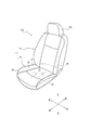
- FIG. 1 shows a vehicle seat 100 including a vehicle seat pad 1 according to a first embodiment of the present invention.
- the seat pad 1 of the present embodiment includes a cushion pad 1a on which a seated person sits and a back pad 1b for supporting the back of the seated person.
- the vehicle seat 100 includes, for example, a skin 101 that covers the front side (seat side) of the seat pad 1, a frame (not shown) that supports the cushion pad 1a from below, and a back pad 1b.
- a frame (not shown) installed on the back side and a headrest 102 installed on the upper side of the back pad 1b for supporting the head of the seated person are provided.
- the skin 101 is made of, for example, a material having good air permeability (cloth or the like).
- the cushion pad 1a and the back pad 1b are each formed of resin foam.
- the resin foam forming the cushion pad 1a and the back pad 1b is preferably a soft resin foam, more preferably a soft polyurethane foam.
- the cushion pad 1a and the back pad 1b can be configured separately from each other.
- each of “upper”, “lower”, “left”, “right”, “front”, and “rear” when viewed from a seated person sitting on the seat pad 1.
- the directions are simply referred to as “up”, “down”, “left”, “right”, “front”, “rear”, etc.
- the cushion pad 1a will be described instead of the back pad 1b. Therefore, the cushion pad 1a may be simply referred to as "seat pad 1".
- the cushion pad 1 a is provided with a seating portion (also referred to as “main pad portion”) 10 configured to support a seated person from below, and on both left and right sides of the seating portion 10. Then, the pair of side pad portions 20 that are raised above the seating portion 10 and are configured to support the seated person from both the left and right sides, and the back pad 1b are located in the rear side of the seating portion 10 and in the vertical direction.
- a seating portion also referred to as “main pad portion” 10 configured to support a seated person from below, and on both left and right sides of the seating portion 10.
- the pair of side pad portions 20 that are raised above the seating portion 10 and are configured to support the seated person from both the left and right sides, and the back pad 1b are located in the rear side of the seating portion 10 and in the vertical direction.
- a back pad facing portion 30 configured so as to face each other.
- a groove 40a extending substantially in the front-rear direction between the seat portion 10 and the side pad portion 20, and a seat portion 10 and a back pad facing portion 30 are provided.
- a groove 40b extending substantially in the left-right direction between the two is provided, and a groove 40c extending substantially in the left-right direction inside the seating portion 10 is provided.
- an attachment tool (not shown) for attaching the skin 101 (FIG. 1) to the cushion pad 1a is arranged inside these grooves 40a, 40b, 40c.
- the boundary line between the seating portion 10 and the side pad portion 20 is the groove width center line of the groove 40a therebetween, and the seating portion 10 and the back pad facing portion 30 are Is the center line of the groove width of the groove 40b between them.
- the grooves 40a and 40b may be located at positions different from the boundary line between the seating portion 10 and the side pad portion 20 and the boundary line between the seating portion 10 and the back pad facing portion 30.
- the grooves 40a to 40c may not be provided on the upper surface US of the cushion pad 1a.
- the seating portion 10 is configured to support the thigh of the seated person from below, and is located rearward of the lower thigh 11 and the lower thigh 11 to support the seated person's hip from below.
- the lower part 12 of the hips is configured.
- a distance L2 that is 45% of the total length L1 of the seating portion 10 in the front-rear direction is separated from the frontmost end position T of the seating portion 10 in the seating portion 10.
- a portion on the front side of the front-rear boundary position B is the lower thigh 11, and a portion on the rear side of the front-rear boundary position B is the lower hip 12. That is, even when the groove 40c is arranged inside the seating portion 10 as in the example of FIG. 2, the front-rear boundary position B between the lower thigh 11 and the lower thigh 12 depends on the position of the groove 40c. Without being prescribed.
- the lower buttocks 12 includes a lower buttocks center portion 12C, a pair of lower buttocks middle portions 12M, and a pair of lower buttocks side portions 12S.
- the lower hips center portion 12C has a length L4 which is 15% of the total length L3 of the lower hips 12 in the left-right direction from the left-right centerline C located at the center of the seating portion 10 in the left-right direction. It is a part on the inner side in the left-right direction than the pair of first left-right positions C1 separated from each other.
- FIG. 3 shows the cushion pad 1a of FIG. 2 in a cross section in the vertical direction (vertical direction) along the line AA of FIG.
- the lower hip portion 12 has a plurality of holes 51 including a bottomless hole 51 and a bottomed hole 51 opening to the upper surface US or the lower surface BS (FIG. 3).
- the lower hip portion 12 has a bottomless hole 51 and a bottomed hole 51 opening to the upper surface US).
- “Unbottomed” with respect to the hole 51 means that the hole 51 is a through hole, that is, that the hole 51 penetrates the lower hip portion 12.
- bottomed means that the hole 51 is a dent, that is, one end of the hole 51 is opened on any surface (the upper surface US or the lower surface BS) of the lower buttocks 12.
- the other end (bottom portion) of the hole 51 does not open on the surface opposite to the open surface of the lower buttocks 12 and ends inside the lower buttocks 12.
- the lower hip portion 12 has a plurality of bottomed holes 51 that are bottomless or open to the upper surface US or the lower surface BS. Therefore, compared with the case where the holes 51 are not provided, the sitting When a person sits down, the hip portion is easily bent, so that the hip portion can be supported softly and the riding comfort can be improved.
- the lower hip portion 12 has a plurality of holes 51 including a bottomless hole 51 and a bottomed hole 51 opening to the upper surface US or the lower surface BS, if the hole 51 is not provided.
- the weight of the seat pad 1 (cushion pad 1a) can be reduced as compared with. Reducing the weight of the seat pad 1 (cushion pad 1a) leads to an improvement in fuel consumption of the vehicle and, in turn, energy saving.
- the bottom part 12 has the bottomless hole 51, it is possible to improve the air permeability and reduce the heat storage property as compared with the case where the bottomless hole 51 is not provided.
- the hole 51 includes a first hole 511, a second hole 512, and a third hole 513.
- the first hole 511 is arranged in the lower hip center portion 12C and includes at least one bottomless hole 51. Further, the first holes 511 may include a bottomed hole 51 that opens to the upper surface US or the lower surface BS of the lower hip center portion 12C (in the example of FIG. 3, the first holes 511 are all bottomless). .. In the example of FIG. 2, 18 first holes 511 arranged in 3 columns and 6 rows are arranged in the lower tail center portion 12C.
- the second hole 512 is a bottomed hole 51 that is disposed in the pair of lower hip intermediate portions 12M and opens on the upper surface US.
- An area from the left-right centerline C to each end in the left-right direction in the lower hip portion 12 is defined as a half portion 12h, and specifically, an area from the left-right centerline C in the lower hip 12 to the left end is defined.
- the left half 12hl and the region from the left-right centerline C to the right end of the lower hip 12 are defined as the right half 12hr, in the example of Fig. 2, the left half 12hl and the right half 12hr
- Six second holes 512 arranged in one column and six rows are arranged in the lower middle portion 12M.
- the third hole 513 is a bottomed hole 51 that is arranged in the pair of lower hip side portions 12S and opens on the upper surface US.
- six third holes 513 arranged in one row and six rows are arranged in the lower bottom side portions 12S of the left half portion 12hl and the right half portion 12hr, respectively.
- the vertical average length L51 of the first holes 511 arranged in the lower hip center portion 12C is the average of the second holes 512 arranged in the pair of lower hip intermediate portions 12M in the vertical direction. Longer than length L52. “The average length L51 of the first hole 511 in the vertical direction” is an average value of the vertical lengths of one or a plurality of the first holes 511 arranged in the lower hip center portion 12C. "The average length L52 of the second hole 512 in the vertical direction” is an average value of the length in the vertical direction of one or a plurality of the second holes 512 arranged in the pair of lower hip intermediate portions 12M. In the example of FIG.
- the average length L51 in the up-down direction of one or a plurality (in this example, a plurality as shown in FIG. 2) of the first holes 511 is in the half portion 12h (left half portion 12hl) on one side. It is longer than the average length L52 in the up-down direction of one or a plurality (in this example, a plurality as shown in FIG. 2) of the second holes 512 arranged in the lower hip intermediate portion 12M. Further, the average length L51 in the vertical direction of the first hole 511 is one or more (in this example, in FIG. 2) arranged in the lower hip middle portion 12M in the other half 12h (right half 12hr). It is longer than the average length L52 in the vertical direction of the plurality of second holes 512 as shown.
- the vertical lengths of the plurality of first holes 511 may be different from each other.
- the first hole 511 that is closest to the center line C in the left-right direction has the longest length in the up-down direction, and the first holes 511 move away from the center line C in the left-right direction to the outer sides in the left-right direction.
- the vertical length of may be short.
- the plurality of first holes 511 are arranged in three rows, but not limited to this, they may be arranged in one row, two rows, or four or more rows.
- the vertical average length L52 of the second holes 512 arranged in the pair of lower hip intermediate portions 12M is larger than the average vertical length L53 of the third holes 513 arranged in the pair of lower hip side portions. Long or equal.
- the “vertical average length L53 of the third holes 513” is an average value of the vertical lengths of one or more third holes 513.
- one or a plurality in this example, as shown in FIG. 2) arranged in the lower middle portion 12M in the half 12h (left half 12hl) on one side from the center line C in the left-right direction.
- the average length L52 of the second hole 512 in the up-down direction is one or a plurality (in this example, a plurality) of the third holes arranged in the lower hip side portion 12S in the half portion 12h (left half portion 12hl). It is longer than or equal to the average length L53 of the holes 513 in the vertical direction (L52>L53 in this example).
- one or a plurality (in this example, a plurality) of the second holes 512 arranged in the lower hip intermediate portion 12M in the half portion 12h (right half portion 12hr) on the other side from the center line C in the left-right direction is arranged in the vertical direction.
- the average length L52 is the average length L53 in the vertical direction of one or a plurality (a plurality in this example) of the third holes 513 arranged in the lower hip side portion 12S in the half portion 12h (right half portion 12hr). Longer or equal (L52>L53 in this example).
- the vertical average length L52 of the second holes 512 arranged in the pair of lower hip intermediate portions 12M is one or more in the pair of lower hip side portions 12S. Is longer than or equal to the average length L53 of the third hole 513 in the vertical direction (L52>L53 in this example).
- the vertical lengths of the plurality of second holes 512 arranged in the pair of lower hip intermediate portions 12M are the same, and therefore, the average vertical length L52 of the second holes 512 is L52. Is the vertical length of each second hole 512.
- the vertical lengths of the plurality of third holes 513 arranged in the pair of lower buttocks side portions 12S are the same, and therefore, the average length L53 of the third holes 513 in the vertical direction is equal to each third length. It is the vertical length of the three holes 513.
- the vertical lengths of the plurality of second holes 512 may be different from each other, and the vertical lengths of the plurality of third holes 513 may be different from each other. ..
- the plurality of second holes 512 are arranged in one row at the lower middle portion 12M of each half portion 12hr, but the present invention is not limited to this, and the half portions 12hr on one side or both sides are arranged. It may be arranged in two or more rows in the left-right direction in the lower middle portion 12M. In this case, the vertical lengths of the plurality of second holes 512 arranged in two or more rows in the left-right direction may be the same or different from each other. When the vertical lengths of the plurality of second holes 512 arranged in two or more rows in the left-right direction are different from each other, the second hole 512 that is closest to the first left-right position C1 among the plurality of second holes 512.
- the length in the vertical direction of the second hole 512 may become shorter as the distance from the first left-right direction position C1 to the outer sides in the left-right direction increases.
- the plurality of third holes 513 are arranged in one row in each lower half side portion 12S of each half portion 12hr, but the present invention is not limited to this, and the lower half side portions 12S of one or both half portions 12hr are not limited to this. It may be arranged in two or more rows in the left-right direction.
- the second hole 512 does not have to be arranged in the lower middle portion 12M, and in that case, the average length L52 of the second hole 512 in the vertical direction is 0.
- the third hole 513 does not have to be arranged in the lower hip side portion 12S, and in that case, the average length L53 in the vertical direction of the third hole 513 is 0.
- the average length L51 of the first hole 511 in the vertical direction is longer than the average length L52 of the second hole 512 in the vertical direction
- the average length L52 of the second hole 512 in the vertical direction is the third hole. Since the average length L53 of the 513 in the vertical direction is longer than or equal to the average length L53, the seat occupant is firmly fixed in the left-right direction when the seat occupant rolls in the lower part 12 of the hip depending on the running state of the vehicle. It can be supported, and the holding property of the seated person can be improved, and the wobble of the seated person can be reduced.
- the second hole 512 and the third hole 513 have openings on the upper surface US, the proportion of the holes 51 on the upper surface US side as going from the center line C in the left-right direction to both outer sides in the left-right direction in the lower hip portion 12. Is high, and the ratio of the holes 51 on the lower surface BS side is low. Accordingly, in the lower hip portion 12, when the hip portion of the seated person shifts to the outside in the left-right direction, the hip portion is likely to bend along the hip portion of the seated person in the portion on the upper surface US side.
- the areas of the plurality of first holes 511 are substantially the same, the areas of the plurality of second holes 512 are substantially the same, and the areas of the plurality of third holes 513 are the same in the horizontal projection plane. Are almost the same.
- the area of the first hole 511, the area of the second hole 512, and the area of the third hole 513 are substantially the same.
- the plurality of pitch intervals p51 in the front-rear direction of the first hole 511 are substantially the same as each other
- the plurality of pitch intervals p52 in the front-rear direction of the second hole 512 are substantially the same as each other
- the pitch interval p52 of the third hole 513 in the front-rear direction is the same.
- the plurality of pitch intervals p51 are substantially the same as each other. Further, the front-rear direction pitch interval p51 of the first holes 511, the front-rear direction pitch interval p52 of the second holes 512, and the front-rear direction pitch interval p53 of the third holes 513 are substantially the same.
- the "pitch interval in the front-rear direction” is the interval between the centers of the pair of holes adjacent to each other in the front-rear direction on the horizontal projection plane.
- the ratio of the total volume of the first holes 511 to the volume of the lower buttocks center portion 12C is the ratio of the total volume of the second holes 512 to the total volume of the pair of lower buttocks intermediate portions 12M.
- the “total volume of the pair of lower hip side portions 12S” is the sum of the volumes of the entire regions defined by the outer edges of the pair of lower hip side portions 12S, that is, the lower hip side portions 12S in the left half 12hl. And the volume of the lower buttocks side part 12S in the right half 12hr, including the volume occupied by the third holes 513 of the respective lower buttocks side 12S of the left half 12hl and the right half 12hr. I'm out.
- the “total volume of the first holes 511” is the total volume of the first holes 511 arranged in the lower tail center portion 11C.
Landscapes
- Engineering & Computer Science (AREA)
- Aviation & Aerospace Engineering (AREA)
- Transportation (AREA)
- Mechanical Engineering (AREA)
- Seats For Vehicles (AREA)
- Mattresses And Other Support Structures For Chairs And Beds (AREA)
- Chair Legs, Seat Parts, And Backrests (AREA)
Abstract
Dans un coussin de siège de véhicule (1) selon la présente invention, une section sous-fessière (12) comprend une pluralité de trous (51) avec ou sans fond. Parmi la pluralité de trous (51), la longueur moyenne (L51), dans la direction verticale, de premiers trous (511) positionnés dans une partie centrale sous-fessière (12C) est supérieure à la longueur moyenne (L52), dans la direction verticale, de deuxièmes trous (512) positionnés dans une partie intermédiaire sous-fessière (12M) ; la longueur moyenne (L52), dans la direction verticale, des deuxièmes trous (512) est supérieure ou égale à la longueur moyenne (L53), dans la direction verticale, de troisièmes trous (513) positionnés dans une partie latérale sous-fessière (12S) ; et les premiers trous (511) comportent au moins un trou sans fond.
Applications Claiming Priority (2)
| Application Number | Priority Date | Filing Date | Title |
|---|---|---|---|
| JP2018234520A JP7239311B2 (ja) | 2018-12-14 | 2018-12-14 | 車両用シートパッド |
| JP2018-234520 | 2018-12-14 |
Publications (1)
| Publication Number | Publication Date |
|---|---|
| WO2020121644A1 true WO2020121644A1 (fr) | 2020-06-18 |
Family
ID=71077220
Family Applications (1)
| Application Number | Title | Priority Date | Filing Date |
|---|---|---|---|
| PCT/JP2019/040775 Ceased WO2020121644A1 (fr) | 2018-12-14 | 2019-10-16 | Coussin de siège de véhicule |
Country Status (2)
| Country | Link |
|---|---|
| JP (1) | JP7239311B2 (fr) |
| WO (1) | WO2020121644A1 (fr) |
Cited By (1)
| Publication number | Priority date | Publication date | Assignee | Title |
|---|---|---|---|---|
| CN117460440A (zh) * | 2021-06-15 | 2024-01-26 | 株式会社亚科迈 | 座垫及座垫的制造方法 |
Citations (4)
| Publication number | Priority date | Publication date | Assignee | Title |
|---|---|---|---|---|
| JPS63163654U (fr) * | 1987-04-14 | 1988-10-25 | ||
| JPH08238141A (ja) * | 1995-03-06 | 1996-09-17 | Toyota Motor Corp | 車両用シート構造 |
| JP2009513297A (ja) * | 2005-10-31 | 2009-04-02 | エコルネス・エイエスエイ | 家具用詰め物 |
| JP2017056078A (ja) * | 2015-09-18 | 2017-03-23 | 株式会社ブリヂストン | 車両用シートパッド |
-
2018
- 2018-12-14 JP JP2018234520A patent/JP7239311B2/ja active Active
-
2019
- 2019-10-16 WO PCT/JP2019/040775 patent/WO2020121644A1/fr not_active Ceased
Patent Citations (4)
| Publication number | Priority date | Publication date | Assignee | Title |
|---|---|---|---|---|
| JPS63163654U (fr) * | 1987-04-14 | 1988-10-25 | ||
| JPH08238141A (ja) * | 1995-03-06 | 1996-09-17 | Toyota Motor Corp | 車両用シート構造 |
| JP2009513297A (ja) * | 2005-10-31 | 2009-04-02 | エコルネス・エイエスエイ | 家具用詰め物 |
| JP2017056078A (ja) * | 2015-09-18 | 2017-03-23 | 株式会社ブリヂストン | 車両用シートパッド |
Cited By (1)
| Publication number | Priority date | Publication date | Assignee | Title |
|---|---|---|---|---|
| CN117460440A (zh) * | 2021-06-15 | 2024-01-26 | 株式会社亚科迈 | 座垫及座垫的制造方法 |
Also Published As
| Publication number | Publication date |
|---|---|
| JP7239311B2 (ja) | 2023-03-14 |
| JP2020093744A (ja) | 2020-06-18 |
Similar Documents
| Publication | Publication Date | Title |
|---|---|---|
| JP6475278B2 (ja) | 車両用シート | |
| EP2983945B1 (fr) | Structure de repose-tête, coussin de repose-tête et siège passager | |
| WO2014003094A1 (fr) | Structure de matériau de rembourrage pour siège de véhicule | |
| WO2014003091A1 (fr) | Structure de plaque inférieure pour siège de véhicule | |
| JP7283248B2 (ja) | 乗物用シート | |
| WO2015129753A1 (fr) | Siège de type selle | |
| JP5242088B2 (ja) | 自動車用座席のクッション | |
| US10661690B2 (en) | Vehicle seat having a recessed central region of the seat pad | |
| CN112714621B (zh) | 缓冲垫 | |
| WO2020121644A1 (fr) | Coussin de siège de véhicule | |
| JP2010254104A (ja) | ヘッドレスト | |
| JP7110931B2 (ja) | 車両用のシート | |
| WO2020121643A1 (fr) | Coussin de siège de véhicule | |
| JP6162372B2 (ja) | 車両用シートのクッション材構造 | |
| JP2022079532A (ja) | 跨座式シート | |
| WO2020121645A1 (fr) | Coussin de siège de véhicule | |
| JP7803161B2 (ja) | 車両用シートバック | |
| JP2006110221A (ja) | 車両用シート | |
| JP7604073B2 (ja) | 座席シート | |
| JP6195473B2 (ja) | 車両用シートのクッション材構造 | |
| JP7087945B2 (ja) | 車両用のシート | |
| US20180297659A1 (en) | Vehicle seat | |
| JPH0322027Y2 (fr) | ||
| WO2020059881A1 (fr) | Coussin de siège de véhicule | |
| JP7236323B2 (ja) | 乗物用シート、当該乗物用シートを備える乗物 |
Legal Events
| Date | Code | Title | Description |
|---|---|---|---|
| 121 | Ep: the epo has been informed by wipo that ep was designated in this application |
Ref document number: 19895703 Country of ref document: EP Kind code of ref document: A1 |
|
| NENP | Non-entry into the national phase |
Ref country code: DE |
|
| 122 | Ep: pct application non-entry in european phase |
Ref document number: 19895703 Country of ref document: EP Kind code of ref document: A1 |