WO2020121646A1 - Procédé de fabrication de tôles d'acier métallisées à chaud et appareil de fabrication de tôles d'acier métallisées à chaud - Google Patents
Procédé de fabrication de tôles d'acier métallisées à chaud et appareil de fabrication de tôles d'acier métallisées à chaud Download PDFInfo
- Publication number
- WO2020121646A1 WO2020121646A1 PCT/JP2019/040837 JP2019040837W WO2020121646A1 WO 2020121646 A1 WO2020121646 A1 WO 2020121646A1 JP 2019040837 W JP2019040837 W JP 2019040837W WO 2020121646 A1 WO2020121646 A1 WO 2020121646A1
- Authority
- WO
- WIPO (PCT)
- Prior art keywords
- steel sheet
- plating
- amount
- steel plate
- back surface
- Prior art date
- Legal status (The legal status is an assumption and is not a legal conclusion. Google has not performed a legal analysis and makes no representation as to the accuracy of the status listed.)
- Ceased
Links
Images


Classifications
-
- C—CHEMISTRY; METALLURGY
- C23—COATING METALLIC MATERIAL; COATING MATERIAL WITH METALLIC MATERIAL; CHEMICAL SURFACE TREATMENT; DIFFUSION TREATMENT OF METALLIC MATERIAL; COATING BY VACUUM EVAPORATION, BY SPUTTERING, BY ION IMPLANTATION OR BY CHEMICAL VAPOUR DEPOSITION, IN GENERAL; INHIBITING CORROSION OF METALLIC MATERIAL OR INCRUSTATION IN GENERAL
- C23C—COATING METALLIC MATERIAL; COATING MATERIAL WITH METALLIC MATERIAL; SURFACE TREATMENT OF METALLIC MATERIAL BY DIFFUSION INTO THE SURFACE, BY CHEMICAL CONVERSION OR SUBSTITUTION; COATING BY VACUUM EVAPORATION, BY SPUTTERING, BY ION IMPLANTATION OR BY CHEMICAL VAPOUR DEPOSITION, IN GENERAL
- C23C2/00—Hot-dipping or immersion processes for applying the coating material in the molten state without affecting the shape; Apparatus therefor
- C23C2/14—Removing excess of molten coatings; Controlling or regulating the coating thickness
- C23C2/16—Removing excess of molten coatings; Controlling or regulating the coating thickness using fluids under pressure, e.g. air knives
- C23C2/18—Removing excess of molten coatings from elongated material
- C23C2/20—Strips; Plates
-
- C—CHEMISTRY; METALLURGY
- C23—COATING METALLIC MATERIAL; COATING MATERIAL WITH METALLIC MATERIAL; CHEMICAL SURFACE TREATMENT; DIFFUSION TREATMENT OF METALLIC MATERIAL; COATING BY VACUUM EVAPORATION, BY SPUTTERING, BY ION IMPLANTATION OR BY CHEMICAL VAPOUR DEPOSITION, IN GENERAL; INHIBITING CORROSION OF METALLIC MATERIAL OR INCRUSTATION IN GENERAL
- C23C—COATING METALLIC MATERIAL; COATING MATERIAL WITH METALLIC MATERIAL; SURFACE TREATMENT OF METALLIC MATERIAL BY DIFFUSION INTO THE SURFACE, BY CHEMICAL CONVERSION OR SUBSTITUTION; COATING BY VACUUM EVAPORATION, BY SPUTTERING, BY ION IMPLANTATION OR BY CHEMICAL VAPOUR DEPOSITION, IN GENERAL
- C23C2/00—Hot-dipping or immersion processes for applying the coating material in the molten state without affecting the shape; Apparatus therefor
- C23C2/34—Hot-dipping or immersion processes for applying the coating material in the molten state without affecting the shape; Apparatus therefor characterised by the shape of the material to be treated
- C23C2/36—Elongated material
- C23C2/40—Plates; Strips
Definitions
- the present invention relates to a method and an apparatus for manufacturing a hot-dip galvanized steel sheet, and more particularly to a technique for reducing variations in the amount of plating adhered on the front and back surfaces of the hot-dip galvanized steel sheet.
- a method of manufacturing a hot-dip galvanized steel sheet for example, a method using an apparatus shown in FIG. 5 is generally used.
- the steel sheet S continuously drawn into the molten metal plating bath 2 is pulled upward from the plating bath 2 and the amount of coating adhered is adjusted by a high pressure gas (wiping gas) injected from the gas expansion device 4.
- the steel plate S is heated in the alloying furnace 8 to alloy the metal forming the plating film with the iron of the steel plate S.
- the surface of the steel sheet S in contact with the sink roll 3 is referred to as the “front surface” of the steel sheet S, and the opposite surface is referred to as the “rear surface”.
- the shape of the steel sheet S at the portion where the amount of plating adhered is not flat, and is generally a shape that is called a C-warp and is curved in an arc shape in the width direction of the steel sheet S (hereinafter also referred to as the plate width direction). is there.
- the plate width direction the width direction of the steel sheet S
- the interval between the steel plate S and the tip of the nozzle of the gas expansion device 4 changes depending on the position in the plate width direction. Therefore, the scraping force by the wiping gas is insufficient in the portion of the steel plate S away from the nozzle, and the coating amount is large, and the plating amount is conversely small in the portion near the nozzle.
- an electromagnet is provided in the vicinity of the gas expansion device 4, and the magnetic force of the electromagnets corrects the shape of the steel sheet to a uniform coating amount.
- the nozzle shape of the gas expansion device 4 has a nozzle width (specifically, the length of the nozzle opening in the plate width direction) of 2 to 2.5 m (2000 to 2500 mm), and the nozzle gap (specifically, The length of the nozzle opening in the vertical direction is 0.6 to 1.2 mm, which is extremely thin and wide.
- the nozzle having such a shape it is not easy to manufacture the nozzle gap in the width direction of the nozzle quite uniformly, and the wiping gas having a uniform gas pressure and a uniform flow rate is provided in the width direction of the nozzle. It's not easy either. That is, it is extremely difficult to make the wiping force completely uniform in the plate width direction.
- the shape of the steel sheet S to be straightened by the electromagnet 5 is not made to be a completely flat shape (flat shape), but the amount of adhered plating or the like is actually measured and the steel sheet shape after straightening is adjusted based on the measured value. There is a need.
- the plurality of electromagnets 5 arranged side by side along the plate width direction are selectively used to correct the warp shape of the steel plate S in the width direction (Patent Document 1). (See paragraph 0043 of Document 1). Specifically, the output is controlled by correcting the current value of the selected electromagnet 5 or changing the position (distance from the steel plate S) (see paragraph 0050 of Patent Document 1).
- Patent Document 1 aims to make the distribution of the alloying degree in the plate width direction uniform, and does not necessarily make the amount of plating adhered in the plate width direction (Patent Document 1). Paragraph 0022). Further, as described above, the wiping force of the gas expansion device 4 is not completely uniform in the plate width direction. Therefore, the distribution of the wiping force in the plate width direction may change between the front surface and the back surface of the steel plate S. In that case, the amount of plating adhered between the front surface and the back surface of the steel plate S is different.
- the shape correction by the electromagnet 5 is repeatedly performed until the distribution of the alloying degree falls within the allowable range.
- the shape correction is repeatedly performed, it does not always converge so that the amount of deposited plating becomes uniform on each of the front surface and the back surface of the steel plate S.
- the present invention has been made in view of the above circumstances, and an object of the present invention is to solve the following objects. Specifically, the present invention solves the above-mentioned problems of the prior art, and a method and an apparatus for manufacturing a hot-dip galvanized steel sheet capable of reducing the variation in the amount of plating applied on the front and back surfaces of the hot-dip galvanized steel sheet. The purpose is to provide.
- the method for producing a hot-dip plated steel sheet of the present invention the steel sheet is continuously drawn into the plating bath of the molten metal, the direction is changed by the direction changing device in the plating bath and pulled from the plating bath.
- a magnetic force is applied in a direction intersecting with the front and back surfaces of the steel sheet to correct the warpage shape of the steel sheet in a non-contact manner, and by an adhesion meter installed on the downstream side of the plating bath, Measure the amount of plating on each of the front and back surfaces, and control the current value of each of the electromagnets to reduce the difference in the amount of plating between the front and back of the steel plate. It is characterized by adjusting.
- the shape of the steel sheet can be corrected so as to reduce the difference. Thereby, it becomes possible to manufacture a hot-dip galvanized steel sheet of good quality.
- the deposition amount meter at each of a plurality of measurement points in the steel sheet set along the width direction, the amount of plating deposition on each of the front surface and the back surface of the steel sheet. Is measured, and the current value of each of the plurality of electromagnets may be controlled to adjust the shape of the straightened steel plate so that the difference becomes zero in at least one or more of the plurality of measurement points.
- the deposition amount meter at each of a plurality of measurement points in the steel sheet set along the width direction, the amount of plating deposition on each of the front surface and the back surface of the steel sheet.
- the shape of the steel plate is changed so that the back surface of the steel plate approaches the gas expansion device at that position. to correct.
- the amount of deposited plating on the back surface at the above-mentioned location is reduced and the amount of deposited plating on the front surface at that location is increased, so that it becomes possible to bring the difference in the deposited quantity between the front surface and the back surface close to zero.
- the current value of each of the plurality of electromagnets may be feedback-controlled so that the difference becomes zero.
- the shape correction of the steel sheet can be repeated until the difference in the amount of adhesion between the front surface and the back surface becomes zero.
- the distance between the tip of the nozzle provided in the gas expansion device and the steel sheet may be changed by adjusting the shape of the straightened steel sheet.
- the apparatus for producing a molten metal-plated steel sheet of the present invention a molten metal plating bath, a steel sheet continuously drawn into the plating bath, in the plating bath to pull up from the plating bath.
- a direction changing device that changes direction a gas expansion device that adjusts the coating amount of the steel plate, and a gas expansion device that corrects the warp shape of the steel plate in a non-contact manner by generating a magnetic force in the direction intersecting the front and back surfaces of the steel plate.
- a plurality of electromagnets arranged on the front and back sides of the steel sheet along the width direction of the steel sheet at at least one position above and below the apparatus, and the plating adhesion on each of the front and back surfaces of the steel sheet on the downstream side of the plating bath.
- the current value of each of the multiple electromagnets is controlled. And an electromagnet control device.
- variation of the coating amount of the surface of a hot-dip galvanized steel sheet and the back surface is reduced, and the quality of a hot-dip galvanized steel plate which has become favorable quality (strictly, the unevenness of the coating amount was suppressed) is manufactured. It is possible.
- One embodiment of the present invention (hereinafter referred to as the present embodiment) manufacturing apparatus for hot-dip galvanized steel sheet, and a method for manufacturing hot-dip galvanized steel sheet using the apparatus will be described in detail below with reference to the accompanying drawings. explain.
- a hot-dip galvanized steel sheet (mainly a hot-dip galvanized steel sheet) is manufactured by using hot-dip zinc as an example of hot-melt metal
- the molten metal is not limited to molten zinc, and other examples include molten tin, molten aluminum, molten lead, and the like.
- downstream side means a more downstream side in the transport direction of the steel sheet S in the manufacturing process of the hot-dip galvanized steel sheet (for clarity, the side closer to the end point in the steel sheet transport path). To do.
- FIG. 1 is a configuration diagram of the manufacturing apparatus 100.
- the manufacturing apparatus 100 includes a plating bath 1 that holds a plating bath 2 of molten zinc to be attached to a strip-shaped steel plate S, a hot dip galvanizing amount attached to the steel plate S pulled from the plating bath 2 ( It is provided with a gas expansion device 4 for adjusting the amount of deposited plating), an electromagnet 5, and a support roll 6 outside the bath. Further, on the downstream side of the support roll 6, an alloying furnace 8 for alloying the plating film, a heat retaining zone 9, and a cooling zone 10 are provided. Further, at a position on the downstream side, an adhesion amount meter 11 and an alloying degree measuring device 12 as a plating film measuring device are provided.
- the manufacturing apparatus 100 controls the electromagnet control device 13 that controls the electromagnet 5, the alloying control device 14 that controls the alloying furnace 8, and the nozzle 4 a of the gas expansion device 4 as a control device that controls each part of the device. And a line control device 17 for controlling these control devices.
- the steel plate S is continuously drawn into the plating bath 2 inside the plating tank 1 and immersed in the plating bath 2.
- the plating bath 2 is provided with a direction changing device that winds the steel plate S to change the direction.
- the sink roll 3 is generally used as the direction changing device.
- a supporting roll 7 in the bath for supporting the steel sheet S whose direction is changed in the plating bath 2 may be provided.
- the support roll 7 in the bath is effective in suppressing the vibration of the steel sheet S and correcting the warp shape, it entraps the dross in the plating bath 2 and gets caught in the steel sheet S, resulting in a so-called dross defect. There is a case to let.
- the vibration can be sufficiently suppressed and the warp shape can be corrected by the electromagnet 5, it is not always necessary to install the support roll 7 in the bath.
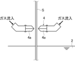
- FIG. 2 is a configuration diagram of the gas expansion device 4 according to the present embodiment.
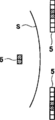
- FIG. 3 is a plan view showing an example of the widthwise arrangement of the electromagnets 5 according to this embodiment.
- the gas expansion device 4 has a pair of nozzles 4a.
- One nozzle 4a faces the front surface of the steel plate S, and the other nozzle 4a faces the back surface of the steel plate S. doing.
- the opening shape of each nozzle 4a is extremely thin and wide in the vertical direction as described in the section "Background Art".
- the electromagnet 5 is installed at least one of above and below the gas expansion device 4. However, since molten zinc may be scattered and accumulated below the gas expansion device 4, it is desirable to install the electromagnet 5 above the gas expansion device 4 as shown in FIG. 1.
- a plurality of electromagnets 5 are arranged along the width direction (plate width direction) of the steel plate S.
- Each of the electromagnets 5 is arranged on both front and back sides of the steel plate S, and is specifically provided to face the front surface or the back surface of the steel plate S. Then, the electromagnet 5 exerts a magnetic force in a direction intersecting with the front surface and the back surface of the steel plate S to suppress the vibration of the steel plate S, and bends and bends when wound around the sink roll 3 and the support roll 7 in the bath. The warp shape of the steel sheet S caused by the return is corrected without contact.
- the arrangement position of the electromagnet 5 in the width direction for example, the arrangement position shown in FIG. 3 can be cited.
- a large number of electromagnets 5 are arranged side by side in the plate width direction, and these electromagnets 5 can be selectively used according to the plate width of the steel plate S and the warp shape in the plate width direction.
- the electromagnet 5 electromagnet 5 with hatching in FIG. 3
- the warp shape of the steel plate S can be adjusted. It is possible.
- a sensor for measuring the distance (spacing) between the steel plate S and the electromagnet 5 or a shape measuring device for the steel plate S may be installed near the electromagnet 5.
- the alloying furnace 8, the heat retaining zone 9 and the cooling zone 10 are for controlling the alloying degree of the plating film by adjusting these temperature conditions appropriately.
- the heating system of the alloying furnace 8 is preferably an induction heating system. This is because the induction heating type can realize uniform heating in the width direction without being affected by the emissivity of the steel sheet surface unlike the gas heating type.
- the adhesion amount meter 11 is a device that measures the amount of plating adhesion on each of the front surface and the back surface of the steel plate S without contact. Further, the deposition amount meter 11 according to the present embodiment can measure the plating deposition amount on each of the front surface and the back surface of the steel plate S at each of a plurality of measurement points on the steel plate S set along the plate width direction. It is possible. That is, the deposition amount meter 11 according to the present embodiment can measure the widthwise distribution of the plating deposition amount on each of the front surface and the back surface of the steel plate S.
- the number and positions of measurement points of the amount of plating adhered are not particularly limited, but it is preferable that the both end positions and the central position of the steel plate S in the plate width direction are included, and the intermediate position between each end position and the central position. More preferably, the position is further included.
- the alloying degree measuring device 12 measures the iron content in the plating film, that is, the alloying degree.
- the alloying degree measuring device 12 does not necessarily need to be able to measure the alloying degree distribution in the width direction.
- the steel plate S is continuously drawn into the plating bath 2, and the sink roll 3 in the plating bath 2 changes the direction of the steel plate S to pull it up from the plating bath 2. Then, wiping gas is sprayed from the nozzle 4a of the gas expansion device 4 toward the steel plate S pulled up from the plating bath 2. Thereby, the amount of plating adhered on each of the front surface and the back surface of the steel plate S is adjusted.
- the steel plate S that has passed through the sink roll 3 is supported by the support roll 6 outside the bath and the support roll 7 inside the bath. Further, the steel plate S receives magnetic force from the plurality of electromagnets 5 above the gas expansion device 4 to prevent vibration and correct the warped shape.
- the steel sheet S with the adjusted amount of plating is heated to a temperature required for alloying in the alloying furnace 8, kept at an appropriate temperature in the heat retaining zone 9, and then cooled in the cooling zone 10.
- a desired degree of alloying can be obtained.
- the plating film is formed on the front and back surfaces of the steel plate S by the above procedure. Then, on the downstream side of the cooling zone 10, the amount of plating applied on each of the front surface and the back surface of the steel sheet S is measured by the adhesion amount meter 11.
- the adhesion amount meter 11 measures the plating adhesion amount at each of a plurality of measurement points set along the plate width direction. As a result, the distribution in the width direction of the coating adhesion amount on each of the front surface and the back surface of the steel plate S is measured.
- the alloying degree of the steel sheet S is measured by the alloying degree measuring device 12. Then, the respective measured values of the coating adhesion amount and the alloying degree are sent to the control computer 16, and the electromagnet 5, the alloying furnace 8 and the gas expansion device 4 are controlled based on these measured values.
- the gas expansion device 4 is adjusted so that the coating amount of plating at each measurement point of the steel plate S becomes an appropriate amount.
- a known adjustment method may be used, for example, the pressure and flow rate of the wiping gas may be adjusted.
- the control value of the output of the gas expansion device 4 is determined according to the adjustment content, and when the control value is sent to the nozzle control device 15, the output of the gas expansion device 4 is controlled by the command of the nozzle control device 15. ..
- the current of each of the plurality of electromagnets 5 is reduced so as to reduce the difference in the plating adhesion amount between the front surface and the back surface of the steel plate S. Control the value.
- the current value of each of the plurality of electromagnets 5 is set so that the difference in the plating adhesion amount becomes zero.
- Feedback control Particularly, in the present embodiment, each current value is feedback-controlled so that the above difference becomes zero at all of the plurality of measurement points.
- the control value of the current value thus obtained is sent to the electromagnet control device 13, and the output of each electromagnet 5 is controlled by the command of the electromagnet control device 13.
- the output of the alloying furnace 8 is controlled so that the desired alloying degree value can be obtained based on the actually measured alloying degree data sent to the control computer 16.
- a known method may be used as the output control method, and for example, the method described in Japanese Patent Application Laid-Open No. 8-269669 may be used.
- the output control value of the alloying furnace 8 is sent to the alloying controller 14, and the output of the alloying furnace 8 is controlled by the command of the alloying controller 14.
- the control of the alloying treatment may be performed not only on the alloying furnace 8 but also on the heat retaining zone 9 and the cooling zone 10.
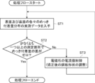
- FIG. 4 is a diagram showing an example of a processing flow of the plating adhesion amount control in the present invention.
- the line control device 17 sends the target values of the plating deposition amount and the alloying degree to the control computer 16.
- the initial condition operating condition before control
- the processing flow of the plating deposition amount control starts in a linked manner.
- the coating weight control first, the coating weight is measured by the coating weight meter 11, and the actual measurement data showing the distribution of the coating weights on the front surface and the back surface of the steel plate S is obtained (ST1 in FIG. 4). Then, it is determined whether or not the difference in the amount of plating adhered between the front surface and the back surface of the steel sheet S is zero at at least one of the measurement points set in the steel sheet S in the plate width direction. (ST2 in FIG. 4).
- the current value of each of the plurality of electromagnets 5 is controlled to correct the shape of the steel sheet S (ST3 in FIG. 4). ..
- step ST3 of FIG. 4 when there is a local difference in the coating amount between the front surface and the back surface of the steel plate S in the plate width direction, the plating at that position is performed.
- the warp shape of the steel sheet S after straightening is adjusted so that the difference in the adhesion amount becomes zero. For example, when the amount of plating on the back surface is larger than the amount of plating on the front surface of the steel plate S at a certain measurement point in the plate width direction, the back surface of the measurement point is brought closer to the tip of the nozzle 4a of the gas expansion device 4. In this way, the shape of the steel plate S after straightening is adjusted.
- the amount of plating adhered on the back surface of the steel sheet S decreases, while the amount of plating adhered on the front surface increases, so that the difference in the amount of plating adhesion approaches zero.
- the above-mentioned steps ST1 to ST3 are performed. repeat. That is, the output of each of the plurality of electromagnets 5 is feedback-controlled, and is repeatedly controlled until the shape of the straightened steel plate S is adjusted so that the difference in the plating adhesion amount at at least one or more measurement points becomes zero. To be done.
- the output control of the gas expansion device 4 may be performed in accordance with the output control of the electromagnet 5 to adjust the plating adhesion amount (strictly, the scraping amount) on each of the front surface and the back surface of the steel plate S.
- the measured alloying degree may be obtained, the output of the alloying furnace 8 may be controlled based on the obtained alloying degree, and the alloying degree of the plating film may be adjusted to an appropriate value. ..
- the plating deposition amount between the front surface and the back surface of the steel plate S is controlled by controlling the current value of each of the plurality of electromagnets 5. Can be reduced. It should be noted that it is sufficient that the difference between the amounts of adhered plating between the front surface and the back surface of the steel sheet S is zero, and the amount of adhered plating on each surface is not necessarily uniform in the plate width direction.
- the hot-dip galvanized steel sheet produced according to the present invention has a uniform coating amount between the front surface and the back surface of the steel sheet, so that unevenness in the coating amount is suppressed, and a plated steel sheet of good quality is obtained. .. Further, since the unevenness of the amount of plating adhered is suppressed, it is possible to suppress the use of excess molten metal and thereby reduce the amount of molten metal used.
- a plurality of measurement points set in the plate width direction are set so that the difference in the plating adhesion amount between the front surface and the back surface of the steel sheet becomes zero.
- the current value of each of the electromagnets was controlled to adjust the shape of the steel sheet after straightening. Specifically, the distance between the tip of the nozzle of the gas expansion device and the back surface of the straightened steel plate (nozzle-steel plate distance) was adjusted as shown in Table 1 below.
- Table 1 shows a value obtained by subtracting the plating adhesion amount on the back surface from the plating adhesion amount on the front surface as a difference in the plating adhesion amount at each measurement location.
- the steel plate shape was flattened without correction.
- the difference between the nozzle-steel plate spacing and the coating adhesion amount in the comparative example is as shown in Table 1 above.
- the measurement points in the plate width direction are the one end position in the plate width direction, the intermediate position between the one end position and the central position (one end side intermediate position), the central position, and the intermediate position between the other end position and the central position. (The intermediate position on the other end side) and the other end position are five positions.
Landscapes
- Chemical & Material Sciences (AREA)
- Chemical Kinetics & Catalysis (AREA)
- Engineering & Computer Science (AREA)
- Materials Engineering (AREA)
- Mechanical Engineering (AREA)
- Metallurgy (AREA)
- Organic Chemistry (AREA)
- Coating With Molten Metal (AREA)
Abstract
La présente invention concerne un procédé et un appareil de fabrication de tôles d'acier métallisées à chaud permettant de réduire la variation du poids de placage entre les surfaces avant et arrière des tôles d'acier métallisées à chaud. Selon la présente invention, dans un procédé et un appareil de fabrication de tôles d'acier métallisées à chaud, la déformation d'une tôle d'acier S est corrigée sans contact grâce à l'application d'une force magnétique dans une direction croisant la surface avant et la surface arrière de la tôle d'acier S au moyen d'une pluralité d'électroaimants 5 disposés sur les surfaces avant et arrière de la tôle d'acier S le long de la largeur de la tôle d'acier S dans au moins une position au-dessus et au-dessous d'un dispositif d'étranglement de gaz 4, le poids du placage sur chacune des surfaces avant et arrière de la tôle d'acier S est mesuré par un dispositif de mesure de poids de placage 11 installé en aval d'un bain de placage 2, et la forme de la tôle d'acier corrigée S est modifiée par réglage de la valeur actuelle de chaque électroaimant parmi la pluralité d'électroaimants 5 de façon à réduire la variation du poids de placage entre les surfaces avant et arrière de la tôle d'acier S.
Priority Applications (3)
| Application Number | Priority Date | Filing Date | Title |
|---|---|---|---|
| MX2021006938A MX2021006938A (es) | 2018-12-11 | 2019-10-17 | Metodo para fabricar chapa de acero revestida con metal por inmersion en caliente y aparato para fabricar chapa de acero revestida con metal por inmersion en caliente. |
| JP2020501838A JPWO2020121646A1 (ja) | 2018-12-11 | 2019-10-17 | 溶融金属めっき鋼板の製造方法、溶融金属めっき鋼板の製造装置 |
| CN201980079447.3A CN113166909A (zh) | 2018-12-11 | 2019-10-17 | 熔融金属镀覆钢板的制造方法、熔融金属镀覆钢板的制造装置 |
Applications Claiming Priority (2)
| Application Number | Priority Date | Filing Date | Title |
|---|---|---|---|
| JP2018-231397 | 2018-12-11 | ||
| JP2018231397 | 2018-12-11 |
Publications (1)
| Publication Number | Publication Date |
|---|---|
| WO2020121646A1 true WO2020121646A1 (fr) | 2020-06-18 |
Family
ID=71077242
Family Applications (1)
| Application Number | Title | Priority Date | Filing Date |
|---|---|---|---|
| PCT/JP2019/040837 Ceased WO2020121646A1 (fr) | 2018-12-11 | 2019-10-17 | Procédé de fabrication de tôles d'acier métallisées à chaud et appareil de fabrication de tôles d'acier métallisées à chaud |
Country Status (4)
| Country | Link |
|---|---|
| JP (1) | JPWO2020121646A1 (fr) |
| CN (1) | CN113166909A (fr) |
| MX (1) | MX2021006938A (fr) |
| WO (1) | WO2020121646A1 (fr) |
Citations (2)
| Publication number | Priority date | Publication date | Assignee | Title |
|---|---|---|---|---|
| JP2004027315A (ja) * | 2002-06-27 | 2004-01-29 | Jfe Steel Kk | 溶融金属めっき鋼板の製造方法および製造装置 |
| WO2013168668A1 (fr) * | 2012-05-10 | 2013-11-14 | 新日鐵住金株式会社 | Procédé et dispositif de commande de forme de tôle d'acier |
Family Cites Families (3)
| Publication number | Priority date | Publication date | Assignee | Title |
|---|---|---|---|---|
| JP3574204B2 (ja) * | 1995-01-24 | 2004-10-06 | 新日本製鐵株式会社 | 溶融めっき鋼板のめっき付着量制御装置及び方法 |
| DE69626628T2 (de) * | 1995-11-10 | 2003-09-11 | Kawasaki Steel Corp., Kobe | Verfahren und vorrichtung zum halten von metallschmelze |
| JP5444706B2 (ja) * | 2008-12-18 | 2014-03-19 | Jfeスチール株式会社 | 金属帯の制御方法及び溶融めっき金属帯の製造方法 |
-
2019
- 2019-10-17 WO PCT/JP2019/040837 patent/WO2020121646A1/fr not_active Ceased
- 2019-10-17 CN CN201980079447.3A patent/CN113166909A/zh active Pending
- 2019-10-17 MX MX2021006938A patent/MX2021006938A/es unknown
- 2019-10-17 JP JP2020501838A patent/JPWO2020121646A1/ja active Pending
Patent Citations (2)
| Publication number | Priority date | Publication date | Assignee | Title |
|---|---|---|---|---|
| JP2004027315A (ja) * | 2002-06-27 | 2004-01-29 | Jfe Steel Kk | 溶融金属めっき鋼板の製造方法および製造装置 |
| WO2013168668A1 (fr) * | 2012-05-10 | 2013-11-14 | 新日鐵住金株式会社 | Procédé et dispositif de commande de forme de tôle d'acier |
Also Published As
| Publication number | Publication date |
|---|---|
| CN113166909A (zh) | 2021-07-23 |
| JPWO2020121646A1 (ja) | 2021-02-15 |
| MX2021006938A (es) | 2021-07-15 |
Similar Documents
| Publication | Publication Date | Title |
|---|---|---|
| JPWO2013168668A1 (ja) | 鋼板形状制御方法及び鋼板形状制御装置 | |
| JP6350663B2 (ja) | 鋼帯の冷却方法及び冷却設備 | |
| WO2004003249A1 (fr) | Procede et appareil de production de tole d'acier plaquee de metal en fusion | |
| WO2020121646A1 (fr) | Procédé de fabrication de tôles d'acier métallisées à chaud et appareil de fabrication de tôles d'acier métallisées à chaud | |
| JP7134591B2 (ja) | 連続溶融亜鉛めっき方法及び連続溶融亜鉛めっき装置 | |
| JP3201260B2 (ja) | 溶融金属めっき鋼板の付着量制御方法 | |
| JPH11100651A (ja) | 連続溶融金属めっき装置 | |
| JP3876810B2 (ja) | 金属帯の制振装置及び金属帯の製造方法 | |
| JPH02254146A (ja) | 誘導加熱装置及び誘導加熱式合金化炉及び合金化方法 | |
| JP5263433B2 (ja) | 金属帯の安定装置および溶融めっき金属帯の製造方法 | |
| JP5223451B2 (ja) | 溶融めっき金属帯の製造方法 | |
| JP5600873B2 (ja) | 溶融めっき鋼帯の製造方法 | |
| JP5644141B2 (ja) | 金属帯の制振及び位置矯正装置、および該装置を用いた溶融めっき金属帯製造方法 | |
| JP3755492B2 (ja) | 合金化溶融亜鉛めっき鋼板及びその製造方法 | |
| JP6187577B2 (ja) | 金属帯の安定装置および溶融めっき金属帯の製造方法 | |
| JP5169089B2 (ja) | 連続溶融金属めっき方法 | |
| JP6648650B2 (ja) | 金属帯の安定装置および溶融めっき金属帯の製造方法 | |
| JP2016169430A (ja) | 溶融亜鉛めっき鋼板の製造方法 | |
| JP2016151032A (ja) | 溶融金属めっき鋼板の製造設備および製造方法 | |
| JP2002275610A (ja) | 金属帯形状制御装置 | |
| JP3114572B2 (ja) | 合金化溶融亜鉛鍍金鋼板の合金化制御方法 | |
| JP3535131B2 (ja) | 溶融めっき鋼帯の製造方法 | |
| JP2015160959A (ja) | 金属帯の非接触制御装置および溶融めっき金属帯の製造方法 | |
| JP2789946B2 (ja) | 合金化溶融亜鉛めっき鋼板の製造方法 | |
| JPH04329857A (ja) | 溶融合金化亜鉛めっき鋼帯の合金化制御方法 |
Legal Events
| Date | Code | Title | Description |
|---|---|---|---|
| ENP | Entry into the national phase |
Ref document number: 2020501838 Country of ref document: JP Kind code of ref document: A |
|
| 121 | Ep: the epo has been informed by wipo that ep was designated in this application |
Ref document number: 19895704 Country of ref document: EP Kind code of ref document: A1 |
|
| NENP | Non-entry into the national phase |
Ref country code: DE |
|
| 122 | Ep: pct application non-entry in european phase |
Ref document number: 19895704 Country of ref document: EP Kind code of ref document: A1 |