WO2020121660A1 - 液体クロマトグラフ質量分析装置 - Google Patents
液体クロマトグラフ質量分析装置 Download PDFInfo
- Publication number
- WO2020121660A1 WO2020121660A1 PCT/JP2019/042053 JP2019042053W WO2020121660A1 WO 2020121660 A1 WO2020121660 A1 WO 2020121660A1 JP 2019042053 W JP2019042053 W JP 2019042053W WO 2020121660 A1 WO2020121660 A1 WO 2020121660A1
- Authority
- WO
- WIPO (PCT)
- Prior art keywords
- flow path
- mass spectrometer
- liquid chromatograph
- valve
- chromatograph mass
- Prior art date
- Legal status (The legal status is an assumption and is not a legal conclusion. Google has not performed a legal analysis and makes no representation as to the accuracy of the status listed.)
- Ceased
Links
Images



Classifications
-
- G—PHYSICS
- G01—MEASURING; TESTING
- G01N—INVESTIGATING OR ANALYSING MATERIALS BY DETERMINING THEIR CHEMICAL OR PHYSICAL PROPERTIES
- G01N30/00—Investigating or analysing materials by separation into components using adsorption, absorption or similar phenomena or using ion-exchange, e.g. chromatography or field flow fractionation
- G01N30/02—Column chromatography
- G01N30/26—Conditioning of the fluid carrier; Flow patterns
- G01N30/38—Flow patterns
- G01N30/46—Flow patterns using more than one column
- G01N30/466—Flow patterns using more than one column with separation columns in parallel
-
- G—PHYSICS
- G01—MEASURING; TESTING
- G01N—INVESTIGATING OR ANALYSING MATERIALS BY DETERMINING THEIR CHEMICAL OR PHYSICAL PROPERTIES
- G01N30/00—Investigating or analysing materials by separation into components using adsorption, absorption or similar phenomena or using ion-exchange, e.g. chromatography or field flow fractionation
- G01N30/02—Column chromatography
- G01N30/62—Detectors specially adapted therefor
- G01N30/72—Mass spectrometers
- G01N30/7233—Mass spectrometers interfaced to liquid or supercritical fluid chromatograph
- G01N30/724—Nebulising, aerosol formation or ionisation
- G01N30/7266—Nebulising, aerosol formation or ionisation by electric field, e.g. electrospray
-
- G—PHYSICS
- G01—MEASURING; TESTING
- G01N—INVESTIGATING OR ANALYSING MATERIALS BY DETERMINING THEIR CHEMICAL OR PHYSICAL PROPERTIES
- G01N27/00—Investigating or analysing materials by the use of electric, electrochemical, or magnetic means
- G01N27/62—Investigating or analysing materials by the use of electric, electrochemical, or magnetic means by investigating the ionisation of gases, e.g. aerosols; by investigating electric discharges, e.g. emission of cathode
- G01N27/622—Ion mobility spectrometry
- G01N27/623—Ion mobility spectrometry combined with mass spectrometry
-
- G—PHYSICS
- G01—MEASURING; TESTING
- G01N—INVESTIGATING OR ANALYSING MATERIALS BY DETERMINING THEIR CHEMICAL OR PHYSICAL PROPERTIES
- G01N30/00—Investigating or analysing materials by separation into components using adsorption, absorption or similar phenomena or using ion-exchange, e.g. chromatography or field flow fractionation
- G01N30/02—Column chromatography
- G01N30/26—Conditioning of the fluid carrier; Flow patterns
- G01N30/28—Control of physical parameters of the fluid carrier
- G01N30/32—Control of physical parameters of the fluid carrier of pressure or speed
-
- G—PHYSICS
- G01—MEASURING; TESTING
- G01N—INVESTIGATING OR ANALYSING MATERIALS BY DETERMINING THEIR CHEMICAL OR PHYSICAL PROPERTIES
- G01N30/00—Investigating or analysing materials by separation into components using adsorption, absorption or similar phenomena or using ion-exchange, e.g. chromatography or field flow fractionation
- G01N30/02—Column chromatography
- G01N30/26—Conditioning of the fluid carrier; Flow patterns
- G01N30/38—Flow patterns
- G01N30/46—Flow patterns using more than one column
-
- G—PHYSICS
- G01—MEASURING; TESTING
- G01N—INVESTIGATING OR ANALYSING MATERIALS BY DETERMINING THEIR CHEMICAL OR PHYSICAL PROPERTIES
- G01N30/00—Investigating or analysing materials by separation into components using adsorption, absorption or similar phenomena or using ion-exchange, e.g. chromatography or field flow fractionation
- G01N30/02—Column chromatography
- G01N30/62—Detectors specially adapted therefor
- G01N30/72—Mass spectrometers
- G01N30/7233—Mass spectrometers interfaced to liquid or supercritical fluid chromatograph
-
- G—PHYSICS
- G01—MEASURING; TESTING
- G01N—INVESTIGATING OR ANALYSING MATERIALS BY DETERMINING THEIR CHEMICAL OR PHYSICAL PROPERTIES
- G01N30/00—Investigating or analysing materials by separation into components using adsorption, absorption or similar phenomena or using ion-exchange, e.g. chromatography or field flow fractionation
- G01N30/02—Column chromatography
- G01N30/86—Signal analysis
- G01N30/8658—Optimising operation parameters
-
- G—PHYSICS
- G01—MEASURING; TESTING
- G01N—INVESTIGATING OR ANALYSING MATERIALS BY DETERMINING THEIR CHEMICAL OR PHYSICAL PROPERTIES
- G01N30/00—Investigating or analysing materials by separation into components using adsorption, absorption or similar phenomena or using ion-exchange, e.g. chromatography or field flow fractionation
- G01N30/02—Column chromatography
- G01N2030/022—Column chromatography characterised by the kind of separation mechanism
- G01N2030/027—Liquid chromatography
-
- G—PHYSICS
- G01—MEASURING; TESTING
- G01N—INVESTIGATING OR ANALYSING MATERIALS BY DETERMINING THEIR CHEMICAL OR PHYSICAL PROPERTIES
- G01N30/00—Investigating or analysing materials by separation into components using adsorption, absorption or similar phenomena or using ion-exchange, e.g. chromatography or field flow fractionation
- G01N30/02—Column chromatography
- G01N30/26—Conditioning of the fluid carrier; Flow patterns
- G01N30/28—Control of physical parameters of the fluid carrier
- G01N30/32—Control of physical parameters of the fluid carrier of pressure or speed
- G01N2030/324—Control of physical parameters of the fluid carrier of pressure or speed speed, flow rate
-
- G—PHYSICS
- G01—MEASURING; TESTING
- G01N—INVESTIGATING OR ANALYSING MATERIALS BY DETERMINING THEIR CHEMICAL OR PHYSICAL PROPERTIES
- G01N30/00—Investigating or analysing materials by separation into components using adsorption, absorption or similar phenomena or using ion-exchange, e.g. chromatography or field flow fractionation
- G01N30/02—Column chromatography
- G01N30/26—Conditioning of the fluid carrier; Flow patterns
- G01N30/38—Flow patterns
- G01N30/46—Flow patterns using more than one column
- G01N30/468—Flow patterns using more than one column involving switching between different column configurations
Definitions
- the present disclosure relates to a liquid chromatograph mass spectrometer.
- a mass spectrometer is a device that ionizes a sample solution, introduces it into a vacuum device, and separates and detects ions according to the mass-to-charge ratio (m/z), and can detect ions with high sensitivity and high accuracy.
- a mass spectrometer is generally used, for example, as a detector of a liquid chromatograph (LC), and a sample is analyzed by an analytical technique called liquid chromatography mass spectrometry (LC-MS).
- Liquid chromatography is a method in which a mobile phase containing a sample is pressurized with a liquid feed pump and passed through a separation column, and the sample is separated according to the difference in the interaction (adsorption, distribution, etc.) with the stationary phase of the separation column. is there.
- the separation column is densely packed with fine porous particles as a stationary phase so as to facilitate interaction with the sample. Therefore, when foreign matter such as dust is mixed or contaminants such as salt are accumulated, the separation column may be clogged and the sensitivity may be lowered. If the separation column becomes clogged, the conductance will decrease and the solution pressure will increase.
- a general LC liquid feed pump is equipped with a pressure gauge, it is possible to detect whether or not a separation column is clogged due to a change in pressure when a constant flow amount of liquid is fed.
- Patent Document 1 discloses a method for determining whether or not a flow path is clogged, "a second flow path 18 that can be switched by a valve 15 is provided on an analysis flow path 8, and a flow meter 17 is provided in the second flow path 18. In preparation, it determines the presence or absence of clogging by measuring the flow rate when necessary" (see the abstract of the same document).
- Patent Document 1 when the flow rate is constant, the pressure of the solution rises in inverse proportion to the conductance of the flow path, so that it is possible to detect a decrease in conductance due to clogging of the flow path.
- the presence or absence of clogging can be confirmed only in the separation column, and it is not possible to specify which part of the flow path from the LC to the mass spectrometer is clogged.
- a method for automatically detecting clogging or leak in the flow path on the downstream side (on the mass spectrometer side) of the separation column has not been known so far.
- the present disclosure provides a liquid chromatograph mass spectrometer that can automatically identify a location where a flow path is clogged and recover in a short time.
- a liquid chromatograph mass spectrometer includes a first flow path that passes through a separation column, a second flow path that does not pass through the separation column, and a first flow path that passes through the first flow path.
- a mass spectrometer for analyzing the sample a first valve for connecting any one of the first channel and the second channel to the mass spectrometer, and driving of the first valve.
- a control unit for controlling and a pressure gauge for measuring the pressure of the second flow path and outputting the pressure to the control unit are provided, and the control unit, when analyzing the sample in the mass spectrometry unit, When the first flow path is connected to the mass spectrometric section and the measured value of the mass spectrometric section is compared with a predetermined threshold value and it is determined to be abnormal, the second flow path is connected to the mass spectrometric analysis section. The first valve is driven so as to be connected to the section.
- FIG. 1 is a schematic diagram showing the configuration of the liquid chromatograph mass spectrometer according to the first embodiment.
- the liquid chromatograph mass spectrometer comprises the solution tanks 1a to 1c, the mass spectrometer 2, the liquid feed pumps 3a to 3c, the separation column 4, the selector valve 5 (first valve), the first flow path 11, and the second flow path.
- a flow path 12, pressure gauges 13a to 13c, a sampler 14, and a control unit 100 are provided.
- the solution tanks 1a and 1b contain a solution serving as a mobile phase.
- a solution serving as a mobile phase.
- the mobile phase solution depending on the sample, those generally used in liquid chromatography can be used.
- water, an aqueous solution of salts, or an organic solvent such as methanol, acetonitrile, or hexane alone or It can be mixed and used.
- the solution tanks 1a and 1b are connected to the first flow path 11 via liquid feed pumps 3a and 3b (first liquid feed pumps).
- the solution tank 1c contains the solution to be fed to the second flow passage 12, and is connected to the second flow passage 12 via the liquid feed pump 3c (second liquid feed pump).
- the solution contained in the solution tank 1c may be the same as or different from the solution contained in the solution tanks 1a and 1b.
- the liquid feed pumps 3a to 3c pressurize and feed the solution in the solution tanks 1a to 1c.
- the pressure gauges 13a and 13b are connected to the liquid feed pumps 3a and 3b for feeding the liquid to the first flow passage 11, and the pressure gauge 13c is provided to the liquid feed pump 3c for feeding the liquid to the second flow passage 12. Connected.
- Each of the pressure gauges 13a to 13c measures the pressure of the solution flowing through the flow path.
- the pressure gauges 13a to 13c it is preferable to use those capable of measuring a pressure within a range that can be pressurized by the liquid feed pumps 3a to 3c, typically a pressure of about 0 to 200 MPa. Further, if the dead volume of the pressure gauges 13a to 13c is large, the time required for the pressure of the solution to stabilize becomes long. Therefore, it is preferable to reduce the dead volume of the pressure gauges 13a to 13c, typically 10 ⁇ L or less. It is preferable to suppress it.
- the first flow channel 11 and the second flow channel 12 are composed of, for example, pipes.
- a sampler 14 is connected to the first flow path 11, and a separation column 4 is connected to the downstream side of the sampler 14.
- the sample is introduced into the first channel 11 by the sampler 14.
- the second flow channel 12 is a flow channel that does not pass through the separation column 4, and no sample is introduced into the second flow channel 12.
- the first flow path 11 Since the first flow path 11 has the separation column 4 having a small conductance on the flow path, the first flow path 11 is typically 0.1 in order to obtain a sufficient flow rate for analysis as the liquid feed pumps 3a and 3b. It is preferable to use a material that can deliver liquid at a pressure of about 100 MPa.
- the liquid feed pump 3c for feeding liquid to the second flow passage 12 serves as the liquid feed pump 3c for feeding liquid to the first flow passage 11.
- a liquid feed pump having a lower upper limit of pressure that can be applied than the liquid pumps 3a and 3b can be used.
- the first channel 11 and the second channel 12 are connected to the selector valve 5, and by switching the selector valve 5, one of the first channel 11 and the second channel 12 is subjected to mass spectrometry. Connected to the section 2. Details of the selector valve 5 will be described later.
- the selector valve 5 will be described later.
- the parts from the solution tanks 1a and 1b to immediately before the mass spectrometric section 2 may be referred to as “liquid chromatograph (LC)”.
- the mass spectrometric unit 2 has a configuration such as an ion source, a vacuum chamber, an ion detection unit, and the like provided in a general mass spectrometric device (MS).
- the mass spectrometric section 2 ionizes the sample introduced from the first flow path 11 with an ion source, introduces it into a vacuum chamber, separates ions for each mass-to-charge ratio (m/z), and uses the ion detection section. Detect ionic strength.
- the ion detector outputs an ion intensity detection signal to the controller 100.
- the ion detector may output the ion current as a detection signal to the controller 100.
- the ion source includes, for example, an electrospray ionization ion source, an atmospheric pressure chemical ionization ion source, an atmospheric pressure photoionization ion source, and the like.
- an electrospray ionization ion source an atmospheric pressure chemical ionization ion source
- an atmospheric pressure photoionization ion source an atmospheric pressure photoionization ion source, and the like.
- the solution containing the sample is sprayed through the capillary of the ion source probe towards the vacuum chamber.
- the appropriate inner diameter of the capillary depends on the flow rate of the liquid chromatograph (LC), and it is preferable to use a thinner capillary as the flow rate decreases.
- the inner diameter of a typical capillary is about 30 ⁇ m to 150 ⁇ m.
- the capillary having an inner diameter larger than 150 ⁇ m is used, the ionization efficiency is lowered, and the distribution of the sample is widened by diffusion while the solution flows through the capillary, which may deteriorate the resolution of LC. Since the capillary has a small inner diameter and is heated depending on the ionization conditions, it is likely to be clogged due to the inclusion of foreign matter and the accumulation of foreign substances.
- the control unit 100 is a computer terminal such as a personal computer, and is configured to control the operation of the entire liquid chromatograph mass spectrometer. Although illustration is omitted, the control unit 100 includes a data processing unit that processes a detection signal (measurement value) of the ion detection unit of the mass spectrometric unit 2, a storage unit that stores various data, a liquid chromatograph mass by a user. An input unit for inputting instructions to the analyzer, a display unit for displaying results of mass spectrometry, various GUI screens, and the like are provided.
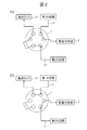
- FIG. 2 is a schematic view showing an example of connection of flow paths by the selector valve 5, (a) showing a state where the first flow path 11 is connected to the mass spectrometric section 2, and (b) showing a second flow path. 12 shows a state in which 12 is connected to the mass spectrometric section 2.
- the control unit 100 drives the selector valve 5 to switch the flow path connected to the mass analysis unit 2. As a result, either the first flow channel 11 or the second flow channel 12 is introduced into the mass spectrometric section 2. As shown in FIG. 2, the flow path that is not connected to the mass spectrometric section 2 is connected to the waste liquid tank 15, which prevents the solution from flowing out.
- FIG. 3 is a flowchart showing the operation of the liquid chromatograph mass spectrometer according to the first embodiment. The operation when an autosampler is used as the sampler 14 will be described below.
- the user prepares a sample in advance and introduces it into the sampler 14.
- an internal standard substance of known concentration By adding an internal standard substance of known concentration to the sample, it is possible to eliminate the influence of instability of adsorption and ionization in the flow channel, so that the signal intensity of the sample can be precisely quantified.
- the user After introducing the sample into the sampler 14, the user inputs an operation start instruction from the input unit of the mass spectrometer 2.
- the control unit 100 Upon receiving the operation start instruction, the control unit 100 operates the liquid chromatograph mass spectrometer in step S1 to start normal measurement. That is, the control unit 100 confirms that the first flow path 11 is connected to the mass spectrometric unit 2 by the selector valve 5, drives the liquid feed pumps 3a and 3b, and moves from the solution tanks 1a and 1b to the first position. The solution is introduced into the first channel 11.
- the pressure gauges 13a and 13b output the pressure values of the liquid feed pumps 3a and 3b to the control unit 100.
- the control unit 100 drives the sampler 14 to introduce the sample into the first flow path 11 and causes the mass spectrometric unit 2 to analyze the sample.
- the ion detector of the mass spectrometer 2 outputs the signal intensity of the sample and the signal intensity of the internal standard substance to the controller 100.
- the output signal of the ion detector may be ionic strength or ionic current.
- the data processing unit of the control unit 100 obtains a chromatogram based on the output signal of the ion detection unit.
- the display unit of the control unit 100 may receive the chromatogram from the data processing unit and display the chromatogram.
- step S2 the control unit 100 compares the signal intensity of the internal standard substance or the output value of the pressure gauges 13a and 13b with a predetermined threshold value stored in the storage unit. Thereby, the control unit 100 determines whether or not there is an abnormality in the measurement.
- the predetermined threshold is a value set based on, for example, a measured value obtained by past measurement or its variation, and the upper limit of the range of values obtained by normal measurement can be used as the threshold.
- No the control unit 100 returns to step S1 and continues normal measurement.
- step S3 the control unit 100 switches the selector valve 5, connects the second flow path 12 to the mass spectrometric unit 2, drives the liquid feed pump 3c, and supplies the solution from the solution tank 1c to the mass spectrometric unit 2. Liquid is delivered at a constant flow rate. Further, the control unit 100 receives the value of the pressure of the liquid feed pump 3c from the pressure gauge 13c.
- step S4 the control unit 100 compares the output value of the pressure gauge 13c with the predetermined threshold value stored in the storage unit.
- the predetermined threshold value to be compared with the output value of the pressure gauge 13c is set, for example, based on the pressure when no clogging has occurred. If there is a blockage between the selector valve 5 and the outlet of the capillary of the ion source, especially when the capillary of the ion source is clogged, the pressure measured by the pressure gauge 13c increases. Therefore, it is possible to determine whether or not there is a clogging between the selector valve 5 and the capillary outlet of the ion source depending on whether or not the pressure measured by the pressure gauge 13c is equal to or higher than the threshold value.
- the control unit 100 switches the selector valve 5 to connect the first flow path 11 to the mass spectrometric unit 2, and returns to step S1 to return to normal measurement.
- the control unit 100 displays, for example, a message requesting maintenance for eliminating the clogging of the ion source on the display unit, and stops the measurement operation.
- step S6 the process proceeds to step S6, and the user performs a recovery process to remove the clogging.
- the restoration process for example, the type and flow rate of the solution in the solution tank 1c are changed. Since the second flow passage 12 does not have a portion having a small conductance such as the separation column 4 on the flow passage, it is possible to directly apply the pressure to the clogged portion by increasing the flow rate, and efficiently push the clogging away. You can Further, as the solution introduced into the second flow path 12, a solvent that easily dissolves impurities (salt or polymer) that causes clogging can be used to efficiently remove clogging.
- the control unit 100 determines whether the output value of the pressure gauge 13c is less than a predetermined threshold value.
- the control unit 100 determines that the clogging has disappeared when the value of the pressure gauge 13c becomes less than the threshold value, switches the selector valve 5 to connect the first flow path 11 to the mass spectrometry unit 2, and returns to step S1. , Can return to normal measurement.
- an internal standard substance having a known concentration can be added to the solution flowing through the second flow path 12 in step S6. In this case, by monitoring the signal intensity of the internal standard substance in addition to the value of the pressure of the solution, it is possible to determine whether the state of the flow channel has returned to normal.
- the liquid chromatograph mass spectrometer switches from the first flow channel 11 to the second flow channel 12 that does not pass through the separation column 4 when the abnormality is detected, and The pressure of the second flow channel 12 is measured, and when the pressure of the second flow channel 12 is equal to or higher than a predetermined threshold value, it is possible to specify that the clogged portion is the ion source. .. Therefore, according to the present embodiment, it is possible to automatically identify the location where the clogging has occurred and to recover from the clogging in a short time.
- FIG. 4 is a schematic diagram showing the configuration of the liquid chromatograph mass spectrometer according to the second embodiment.
- the first flow channel 11 is branched into three, and three separation columns 4 passing through the branched first flow channels 11 are provided.
- the selector valves 6 and 7 (second valve) on the upstream side and the downstream side of the three separation columns 4, respectively, which is different from the first embodiment.
- the characteristics of the plurality of separation columns 4 may be the same or different.
- the control unit 100 controls driving of the selector valves 6 and 7 to select the separation column 4 to be used for measurement.
- the number of separation columns 4 is not limited to three, and other configurations and operations are the same as those in the first embodiment, and thus description thereof will be omitted.
- the liquid chromatograph mass spectrometer according to the present embodiment has the plurality of separation columns 4, the characteristics of the plurality of separation columns 4 can be different and the separation column 4 can be selected according to the characteristics of the sample to be measured.
- a plurality of separation columns 4 having similar characteristics can be used for parallel analysis, and the analysis can be introduced into the mass spectrometric section 2 for a time around the peak, which has the advantage of improving the throughput.
- the liquid chromatograph mass spectrometer of the present embodiment is provided with a plurality of separation columns 4, so that the number of selector valves increases and the flow path becomes complicated. Further, the selector valves 6 and 7 may be clogged, or carryover due to the sample remaining on the selector valves 6 and 7 may occur.
- the first flow path 11 is switched to the second flow path 12 that does not pass through the separation column 4, and the pressure in the second flow path 12 is measured. ..
- the pressure in the second flow path 12 is equal to or higher than a predetermined threshold value, it is possible to specify that the ion source is clogged, and when the pressure in the second flow path 12 is lower than the predetermined threshold value, separation is performed. It is possible to specify that the column 4 or the selector valve 6 or 7 is clogged. Therefore, according to the present embodiment, it is possible to automatically identify the location where the clogging has occurred and to recover from the clogging in a short time.
- FIG. 5 is a schematic diagram showing the configuration of the liquid chromatograph mass spectrometer according to the third embodiment.
- at least one of the plurality of separation columns 4 included in the liquid chromatograph mass spectrometer according to the second embodiment is a hollow dummy column 10, and the separation column 4
- the flow paths can be switched by the selector valves 6 and 7 (second valve) provided on the upstream side and the downstream side of the dummy column 10, respectively.
- the flow path that passes through the separation column 4 is the first flow path 11 and the flow path that passes through the dummy column 10 is the second flow path 12.
- the dummy column 10 is provided in parallel with the plurality of separation columns 4, and the second flow channel 12 is a flow channel that passes through the dummy column 10.
- the dummy column 10 is a hollow column with no packing material inside. Therefore, the dummy column 10 has a larger conductance than the separation column 4.
- the control unit 100 connects either one of the plurality of first flow paths 11 or the second flow path 12 to the mass analysis unit 2 by switching the selector valves 6 and 7.
- Other configurations of the device are the same as those in the first and second embodiments, and thus the description thereof will be omitted.
- step S1 the solution is sent from the solution tank 1a by the solution sending pump 3a (first solution sending pump).
- the control unit 100 switches the selector valves 6 and 7 (step S3), and the second flow through the dummy column 10 is performed.
- the path 12 is connected to the mass spectrometric section 2, the solution is sent from the solution tank 1b by the solution sending pump 3b (second solution sending pump), and the pressure in the second channel 12 is measured by the pressure gauge 13b (step S4).
- Other operations are the same as the operations in the first embodiment, and thus detailed description will be omitted.
- the second flow passage 12 is not a pipe as in the first embodiment, but a dummy column provided in parallel with the separation column 4 of the first flow passage 11.
- a configuration that passes through 10 it is possible to simplify the configuration of the device without providing a special flow path and reduce the manufacturing cost.
- the dummy column 10 can be removed similarly to the separation column 4, it can be easily replaced with another column.
- it is possible to determine whether there is a clogging between the liquid delivery pump 3b and the capillary outlet of the ion source it is possible to determine whether the clogging occurs on the separation column 4 side or the ion source side. It can be identified automatically and can recover from a clogging in a short time.
- FIG. 6 is a schematic diagram showing the configuration of the mass spectrometric unit according to the fourth embodiment.
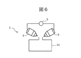
- the mass spectrometer 2 has two or more ion source probes 9, and a selector valve 8 (the first valve for switching a plurality of ion source probes) is used. 3 valve) and is different from the first embodiment. Switching of the selector valve 8 is controlled by the control unit 100.
- the ion source probe 9 has a capillary, and the outlet of the capillary is arranged toward the vacuum chamber 16.
- the other device configuration is the same as that of the first embodiment, and thus the description thereof is omitted.
- the present embodiment similarly to the first embodiment, when an abnormality is detected, the first flow path 11 is switched to the second flow path 12 that does not pass through the separation column 4,
- the configuration is such that the pressure in the second flow path 12 is measured.
- the present embodiment it is possible to automatically identify the location where the clogging has occurred, and it is possible to recover from the clogging in a short time.
- the present embodiment has a configuration in which the flow path is switched to another ion source probe 9 when it is determined that there is a blockage between the selector valve 5 and the capillary outlet of the ion source. This makes it possible to recover from the clogging more reliably and in a short time.
- the present disclosure is not limited to the above-described embodiments and includes various modifications.
- the above-described embodiments have been described in detail in order to explain the present disclosure in an easy-to-understand manner, and it is not necessary to include all the configurations described.
- part of one embodiment can be replaced with the configuration of another embodiment.
- the configuration of another embodiment can be added to the configuration of one embodiment.
- a part of the configuration of each embodiment may be added, deleted, or replaced with a part of the configuration of another embodiment.
Landscapes
- Physics & Mathematics (AREA)
- Chemical & Material Sciences (AREA)
- Health & Medical Sciences (AREA)
- Life Sciences & Earth Sciences (AREA)
- Immunology (AREA)
- Analytical Chemistry (AREA)
- Biochemistry (AREA)
- General Health & Medical Sciences (AREA)
- General Physics & Mathematics (AREA)
- Pathology (AREA)
- Spectroscopy & Molecular Physics (AREA)
- Chemical Kinetics & Catalysis (AREA)
- Electrochemistry (AREA)
- Molecular Biology (AREA)
- Dispersion Chemistry (AREA)
- Other Investigation Or Analysis Of Materials By Electrical Means (AREA)
Abstract
流路の詰まりが生じた箇所を自動的に特定し、短時間で復帰できる液体クロマトグラフ質量分析装置を提供する。本開示の液体クロマトグラフ質量分析装置は、分離カラムを通る第1の流路と、分離カラムを通らない第2の流路と、第1の流路及び第2の流路の下流側に設けられ、第1の流路を通過した試料を分析する質量分析部と、第1の流路及び第2の流路のうちいずれか一方を質量分析部に接続する第1のバルブと、第1のバルブの駆動を制御する制御部と、第2の流路の圧力を測定し、制御部に出力する圧力計と、を備える。制御部は、質量分析部における試料の分析の際に、第1の流路を質量分析部に接続し、質量分析部の測定値と所定の閾値とを比較して、異常であると判定した場合に、第2の流路を質量分析部に接続するように第1のバルブを駆動する。
Description
本開示は、液体クロマトグラフ質量分析装置に関する。
質量分析装置は、試料溶液をイオン化して真空装置に導入し、質量電荷比(m/z)に応じてイオンを分離して検出する装置であり、高感度かつ高精度にイオンを検出できる。質量分析装置は、例えば液体クロマトグラフ(LC)の検出器として一般的に用いられ、液体クロマトグラフィー質量分析(LC-MS)と呼ばれる分析手法により試料の分析が行われる。
液体クロマトグラフィーは、試料を含む移動相を送液ポンプで加圧して分離カラムを通過させ、分離カラムの固定相との相互作用(吸着、分配など)の差に応じて試料を分離する手法である。分離カラムは、試料との相互作用が起こりやすいように、固定相として微細な多孔質粒子が内部に密に充填されている。そのため、埃などの異物混入や塩などの夾雑物の堆積が発生すると、分離カラムが詰まり、感度の低下を引き起こす場合がある。分離カラムが詰まるとコンダクタンスが低下して、溶液の圧力が上昇する。
一般的なLCの送液ポンプは圧力計を備えているため、一定流量の送液を行った場合の圧力の変化により、分離カラムに詰まりが生じたどうかを検知することができる。
特許文献1には、流路の詰まりの有無を判断する方法として、「分析流路8上にバルブ15により切り換え可能な第2流路18を設け、第2流路18内に流量計17を備えて、必要なときに流量を計測することにより、詰まりの有無を判断する」ことが記載されている(同文献の要約参照)。
試料が流れる流路が詰まった場合、流路の詰まりによる感度低下から復帰するためには、詰まり箇所を特定して詰まりを取り除く必要がある。しかし、公知の液体クロマトグラフ質量分析装置では、詰まりが生じた箇所をユーザーが手動で特定する必要があり、詰まった箇所の特定に長い時間を要していた。
また、特許文献1においては、流量が一定であれば溶液の圧力は流路のコンダクタンスに反比例して上昇するため、流路の詰まりによるコンダクタンスの減少を検知することができる。しかし、特許文献1に記載の方法では、詰まりの有無を確認できるのは分離カラムについてのみであり、LCから質量分析装置までの流路のどの部分が詰まったのかを特定することができない。特に、分離カラムよりも下流側(質量分析装置側)の流路の詰まりやリークを自動で検出する方法はこれまで知られていなかった。
そこで、本開示は、流路の詰まりが生じた箇所を自動的に特定し、短時間で復帰できる液体クロマトグラフ質量分析装置を提供する。
上記課題を解決するために、本開示の液体クロマトグラフ質量分析装置は、分離カラムを通る第1の流路と、分離カラムを通らない第2の流路と、前記第1の流路を通過した試料を分析する質量分析部と、前記第1の流路及び前記第2の流路のうちいずれか一方を前記質量分析部に接続する第1のバルブと、前記第1のバルブの駆動を制御する制御部と、前記第2の流路の圧力を測定し、前記制御部に出力する圧力計と、を備え、前記制御部は、前記質量分析部における前記試料の分析の際に、前記第1の流路を前記質量分析部に接続し、前記質量分析部の測定値と所定の閾値とを比較して、異常であると判定した場合に、前記第2の流路を前記質量分析部に接続するように前記第1のバルブを駆動することを特徴とする。
本開示に関連する更なる特徴は、本明細書の記述、添付図面から明らかになるものである。また、本開示の態様は、要素及び多様な要素の組み合わせ及び以降の詳細な記述と添付される特許請求の範囲の様態により達成され実現される。
本明細書の記述は典型的な例示に過ぎず、本開示の特許請求の範囲又は適用例を如何なる意味に於いても限定するものではないことを理解する必要がある。
本明細書の記述は典型的な例示に過ぎず、本開示の特許請求の範囲又は適用例を如何なる意味に於いても限定するものではないことを理解する必要がある。
本開示によれば、液体クロマトグラフ質量分析装置において流路の詰まりが生じた箇所を自動的に特定し、短時間で復帰できる。
上記以外の課題、構成及び効果は、以下の実施の形態の説明により明らかにされる。
上記以外の課題、構成及び効果は、以下の実施の形態の説明により明らかにされる。
[第1の実施形態]
<装置構成>
図1は、第1の実施形態に係る液体クロマトグラフ質量分析装置の構成を示す模式図である。液体クロマトグラフ質量分析装置は、溶液タンク1a~1c、質量分析部2、送液ポンプ3a~3c、分離カラム4、セレクターバルブ5(第1のバルブ)、第1の流路11、第2の流路12、圧力計13a~13c、サンプラー14並びに制御部100を備える。
<装置構成>
図1は、第1の実施形態に係る液体クロマトグラフ質量分析装置の構成を示す模式図である。液体クロマトグラフ質量分析装置は、溶液タンク1a~1c、質量分析部2、送液ポンプ3a~3c、分離カラム4、セレクターバルブ5(第1のバルブ)、第1の流路11、第2の流路12、圧力計13a~13c、サンプラー14並びに制御部100を備える。
溶液タンク1a及び1bは、移動相となる溶液を収容する。移動相となる溶液としては、試料に応じて、一般に液体クロマトグラフィーで用いられるものを使用することができ、例えば水、塩類の水溶液や、メタノール、アセトニトリル、ヘキサンなどの有機溶媒などを単独であるいは混合して用いることができる。溶液タンク1a及び1bは、送液ポンプ3a及び3b(第1の送液ポンプ)を介して第1の流路11に接続される。
溶液タンク1cは、第2の流路12に送液される溶液を収容し、送液ポンプ3c(第2の送液ポンプ)を介して第2の流路12に接続される。溶液タンク1cに収容される溶液は、溶液タンク1a及び1bに収容される溶液と同じであってもよいし、異なっていてもよい。
送液ポンプ3a~3cは、溶液タンク1a~1c内の溶液を加圧して送液する。第1の流路11に送液する送液ポンプ3a及び3bには、それぞれ圧力計13a及び13bが接続され、第2の流路12に送液する送液ポンプ3cには、圧力計13cが接続される。
圧力計13a~13cは、それぞれ流路を流れる溶液の圧力を測定する。圧力計13a~13cとして、送液ポンプ3a~3cで加圧できる範囲の圧力、典型的には0~200MPa程度の圧力を測定可能なものを用いることが好ましい。また、圧力計13a~13cのデッドボリュームが大きいと溶液の圧力が安定するまでに要する時間が長くなるため、圧力計13a~13cのデッドボリュームを小さくすることが好ましく、典型的には10μL以下に抑えることが好ましい。
第1の流路11及び第2の流路12は、例えば配管により構成される。第1の流路11にはサンプラー14が接続され、サンプラー14の下流側に分離カラム4が接続される。サンプラー14として、例えばオートサンプラーやマニュアルインジェクター等を用いることができる。試料は、サンプラー14により第1の流路11に導入される。第2の流路12は分離カラム4を通らない流路であり、第2の流路12に試料は導入されない。
第1の流路11は、コンダクタンスが小さい分離カラム4を流路上に有するため、送液ポンプ3a及び3bとして、分析を行うのに十分な流量を得られるように、典型的には0.1~100MPa程度の圧力で送液可能なものを用いることが好ましい。一方、第2の流路12は第1の流路11に比べてコンダクタンスが大きいため、第2の流路12に送液する送液ポンプ3cとして、第1の流路11に送液する送液ポンプ3a及び3bよりも加圧できる圧力の上限が低い送液ポンプを用いることができる。
第1の流路11及び第2の流路12は、セレクターバルブ5に接続され、セレクターバルブ5の切り替えにより、第1の流路11及び第2の流路12のうちいずれか一方が質量分析部2に接続される。セレクターバルブ5の詳細は後述する。以下、本実施形態の液体クロマトグラフ質量分析装置において、溶液タンク1a及び1bから質量分析部2の直前までを「液体クロマトグラフ(LC)」という場合がある。
質量分析部2は、図示は省略しているが、イオン源、真空チャンバ、イオン検出部等、一般の質量分析装置(MS)が備える構成を有する。質量分析部2は、第1の流路11から導入された試料をイオン源でイオン化し、真空チャンバに導入して、質量電荷比(m/z)ごとにイオンを分離し、イオン検出部によりイオン強度を検出する。イオン検出部は、イオン強度の検出信号を制御部100に出力する。また、イオン検出部は、イオン電流を検出信号として制御部100に出力してもよい。
イオン源として、例えばエレクトロスプレーイオン化イオン源、大気圧化学イオン化イオン源、大気圧光イオン化イオン源などが挙げられる。何れのイオン化方法においても、試料を含む溶液は、イオン源プローブのキャピラリーを通して真空チャンバに向かって噴霧される。
適切なキャピラリーの内径は液体クロマトグラフ(LC)の流量に依存し、流量が少ないほど細いキャピラリーを用いることが好ましい。典型的なキャピラリーの内径は30μm~150μm程度である。150μmより太い内径のキャピラリーを使用した場合、イオン化効率が低下するほか、キャピラリーを溶液が流れる間に拡散により試料の分布が広がるため、LCの分離能も劣化する虞がある。キャピラリーは内径が細く、かつイオン化の条件によっては加熱されるため、異物の混入や夾雑物の堆積により詰まりやすい。
制御部100は、例えばパーソナルコンピュータ等のコンピュータ端末であり、液体クロマトグラフ質量分析装置全体の動作を制御するよう構成される。図示は省略しているが、制御部100は、質量分析部2のイオン検出部の検出信号(測定値)の処理を行うデータ処理部、各種データを記憶する記憶部、ユーザーが液体クロマトグラフ質量分析装置に対し指示を入力するための入力部、質量分析の結果や各種GUI画面等を表示する表示部などを備える。
図2は、セレクターバルブ5による流路の接続例を示す模式図であり、(a)は第1の流路11が質量分析部2に接続された状態、(b)は第2の流路12が質量分析部2に接続された状態を示す。
制御部100は、セレクターバルブ5を駆動して、質量分析部2につながる流路を切り替える。これにより、第1の流路11と第2の流路12のいずれか一方が、質量分析部2に導入される。図2に示すように、質量分析部2につながらない流路は廃液タンク15に接続され、これにより溶液の外部への流出が防止される。
<動作>
図3は、第1の実施形態に係る液体クロマトグラフ質量分析装置の動作を示すフローチャートである。以下において、サンプラー14としてオートサンプラーを用いる場合の動作を説明する。
図3は、第1の実施形態に係る液体クロマトグラフ質量分析装置の動作を示すフローチャートである。以下において、サンプラー14としてオートサンプラーを用いる場合の動作を説明する。
まず、ユーザーは、予め試料を調製し、サンプラー14に導入しておく。試料に既知濃度の内部標準物質を添加することで、流路への吸着やイオン化の不安定性の影響を排除できるため、試料の信号強度を精密に定量することができる。ユーザーは、サンプラー14に試料を導入した後、質量分析部2の入力部から動作の開始指示を入力する。
制御部100は、動作の開始指示を受信すると、ステップS1において、液体クロマトグラフ質量分析装置を動作させ、通常の測定を開始する。すなわち、制御部100は、セレクターバルブ5により第1の流路11が質量分析部2に接続されていることを確認し、送液ポンプ3a及び3bを駆動して、溶液タンク1a及び1bから第1の流路11に溶液を導入する。圧力計13a及び13bは、送液ポンプ3a及び3bの圧力の値を制御部100に出力する。また、制御部100は、サンプラー14を駆動して第1の流路11に試料を導入し、質量分析部2に試料の分析を行わせる。質量分析部2のイオン検出部は、試料の信号強度及び内部標準物質の信号強度を制御部100に出力する。イオン検出部の出力信号は、イオン強度であってもよいし、イオン電流であってもよい。
制御部100のデータ処理部は、イオン検出部の出力信号に基づいて、クロマトグラムを得る。制御部100の表示部は、データ処理部からクロマトグラムを受信して、該クロマトグラムを表示してもよい。
ステップS2において、制御部100は、内部標準物質の信号強度、あるいは圧力計13a及び13bの出力値と、記憶部に記憶された所定の閾値とを比較する。これにより、制御部100は、測定に異常があるか否かを判定する。所定の閾値は、例えば過去の測定により得られた測定値やそのばらつきに基づいて設定される値であり、正常な測定で得られる値の範囲の上限を閾値とすることができる。制御部100は、異常がないと判断した場合(No)、ステップS1に戻り、通常の測定を継続する。
制御部100が異常を検知した場合(Yes)、LC又は質量分析部2において詰まりが生じた可能性が高いので、詰まりが生じた箇所を特定するために、ステップS3に移行する。ステップS3において、制御部100は、セレクターバルブ5を切り替え、第2の流路12を質量分析部2に接続し、送液ポンプ3cを駆動して、溶液タンク1cから質量分析部2に溶液を一定流量で送液する。また、制御部100は、圧力計13cから送液ポンプ3cの圧力の値を受信する。
ステップS4において、制御部100は、圧力計13cの出力値と、記憶部に記憶された所定の閾値とを比較する。圧力計13cの出力値と比較される所定の閾値は、例えば、詰まりが生じていない場合の圧力に基づいて設定される。セレクターバルブ5とイオン源のキャピラリーの出口との間、特にイオン源のキャピラリーに詰まりが生じると、圧力計13cで測定される圧力が上昇する。このため、圧力計13cで計測した圧力が閾値以上であるかどうかによって、セレクターバルブ5とイオン源のキャピラリー出口との間に詰まりがあるかどうかを判断することができる。
圧力計13cで計測した圧力が閾値未満であった場合(No)、セレクターバルブ5とイオン源のキャピラリー出口との間に詰まりは生じておらず、詰まりが生じた箇所はLC側、すなわち分離カラム4であることが想定できる。その後、ステップS5に移行し、ユーザーは、分離カラム4の交換を行う。制御部100は、分離カラム4が交換されたことを検知すると、セレクターバルブ5を切り替えて第1の流路11を質量分析部2に接続し、ステップS1に戻り、通常の測定に復帰する。
圧力計13cで計測した圧力が閾値以上であった場合(Yes)、セレクターバルブ5とイオン源のキャピラリー出口との間に詰まりがあることがわかる。このとき、制御部100は、例えば、イオン源の詰まりを解消するためのメンテナンスを要求するメッセージを表示部に表示し、測定動作を停止する。
その後、ステップS6に移行し、ユーザーは、詰まりを取り除くための復帰処理を行う。復帰処理として、例えば、溶液タンク1cの溶液の種類や流量の変更を行う。第2の流路12は、流路上に分離カラム4などのコンダクタンスが小さい部分がないため、流量を上げることで詰まっている箇所に直接圧力を印加することができ、効率的に詰まりを押し流すことができる。また、第2の流路12に導入する溶液として、詰まりの原因となる夾雑物(塩や高分子)を溶解しやすい溶媒を用いることで、効率よく詰まりを除去することができる。具体的には、第2の流路12に導入する溶液として、塩を溶解するには純水、高分子を溶解するにはイソプロパノールなどの有機溶媒が適している。本ステップにおいて、制御部100は、圧力計13cの出力値が所定の閾値未満であるかを判断する。
制御部100は、圧力計13cの値が閾値未満となった時点で詰まりがなくなったと判断し、セレクターバルブ5を切り替えて第1の流路11を質量分析部2に接続し、ステップS1に戻り、通常の測定に復帰することができる。なお、ステップS6において第2の流路12に流す溶液に対し、既知濃度の内部標準物質を添加することもできる。この場合、溶液の圧力の値に加えて内部標準物質の信号強度をモニタすることで、流路の状態が正常に復帰したかを判断することができる。
<技術的効果>
以上のように、本実施形態に係る液体クロマトグラフ質量分析装置は、異常を検知した場合に、第1の流路11から、分離カラム4を通らない第2の流路12に切り替え、第2の流路12の圧力を測定するという構成を有し、第2の流路12の圧力が所定の閾値以上であった場合に、詰まりが生じた箇所がイオン源であると特定することができる。従って、本実施形態によれば、詰まりが生じた箇所を自動的に特定することができ、短時間で詰まりから復帰することができる。
以上のように、本実施形態に係る液体クロマトグラフ質量分析装置は、異常を検知した場合に、第1の流路11から、分離カラム4を通らない第2の流路12に切り替え、第2の流路12の圧力を測定するという構成を有し、第2の流路12の圧力が所定の閾値以上であった場合に、詰まりが生じた箇所がイオン源であると特定することができる。従って、本実施形態によれば、詰まりが生じた箇所を自動的に特定することができ、短時間で詰まりから復帰することができる。
[第2の実施形態]
<装置構成>
図4は、第2の実施形態に係る液体クロマトグラフ質量分析装置の構成を示す模式図である。図4に示すように、本実施形態に係る液体クロマトグラフ質量分析装置は、第1の流路11が3つに分岐し、それぞれが分岐した第1の流路11を通る3つの分離カラム4を有し、3つの分離カラム4の上流側及び下流側にそれぞれセレクターバルブ6及び7(第2のバルブ)を有する点で、第1の実施形態と異なっている。複数の分離カラム4の特性は、それぞれ同様であってもよいし、異なっていてもよい。制御部100は、セレクターバルブ6及び7の駆動を制御して、測定に供する分離カラム4の選択を行う。分離カラム4の数は3つに限定されるものではなく、その他の構成や、動作については第1の実施形態と同様であるため、説明を省略する。
<装置構成>
図4は、第2の実施形態に係る液体クロマトグラフ質量分析装置の構成を示す模式図である。図4に示すように、本実施形態に係る液体クロマトグラフ質量分析装置は、第1の流路11が3つに分岐し、それぞれが分岐した第1の流路11を通る3つの分離カラム4を有し、3つの分離カラム4の上流側及び下流側にそれぞれセレクターバルブ6及び7(第2のバルブ)を有する点で、第1の実施形態と異なっている。複数の分離カラム4の特性は、それぞれ同様であってもよいし、異なっていてもよい。制御部100は、セレクターバルブ6及び7の駆動を制御して、測定に供する分離カラム4の選択を行う。分離カラム4の数は3つに限定されるものではなく、その他の構成や、動作については第1の実施形態と同様であるため、説明を省略する。
<技術的効果>
本実施形態に係る液体クロマトグラフ質量分析装置においては、複数の分離カラム4を有するため、複数の分離カラム4の特性を異ならせ、測定する試料の特性によって分離カラム4を選択することができる。あるいは同様の特性を有する複数の分離カラム4を用いて並列に分析を行い、ピークが出る付近の時間だけ質量分析部2に導入することができ、これによりスループットを向上できるという利点がある。
本実施形態に係る液体クロマトグラフ質量分析装置においては、複数の分離カラム4を有するため、複数の分離カラム4の特性を異ならせ、測定する試料の特性によって分離カラム4を選択することができる。あるいは同様の特性を有する複数の分離カラム4を用いて並列に分析を行い、ピークが出る付近の時間だけ質量分析部2に導入することができ、これによりスループットを向上できるという利点がある。
なお、本実施形態の液体クロマトグラフ質量分析装置は、複数の分離カラム4を備えることによりセレクターバルブの数が増加し流路が複雑になる。また、セレクターバルブ6及び7に詰まりが生じたり、セレクターバルブ6及び7に残留した試料によるキャリーオーバーが生じたりする虞がある。
ここで、特許文献1に記載の液体クロマトグラフ分取装置において、本実施形態と同様に複数の分離カラムを設け、送液ポンプの圧力を測定して詰まりを検出したとしても、詰まりが生じた箇所がセレクターバルブであるのか、分離カラムであるのか、又はイオン源であるのかを特定することはできない。従って、ユーザーにより詰まり箇所を特定する必要があるため、手間がかかる。
一方、本実施形態によれば、異常を検知した場合に、第1の流路11から、分離カラム4を通らない第2の流路12に切り替え、第2の流路12の圧力を測定する。第2の流路12の圧力が所定の閾値以上であった場合に、イオン源に詰まりがあることが特定でき、第2の流路12の圧力が所定の閾値未満であった場合に、分離カラム4、セレクターバルブ6及び7のいずれかに詰まりがあることを特定できる。従って、本実施形態によれば、詰まりが生じた箇所を自動的に特定することができ、短時間で詰まりから復帰することができる。
[第3の実施形態]
<装置構成>
図5は、第3の実施形態に係る液体クロマトグラフ質量分析装置の構成を示す模式図である。図5に示すように、本実施形態においては、第2の実施形態に係る液体クロマトグラフ質量分析装置が備える複数の分離カラム4のうちの少なくとも1つを中空のダミーカラム10とし、分離カラム4及びダミーカラム10の上流側及び下流側にそれぞれ設けられたセレクターバルブ6及び7(第2のバルブ)により流路の切り替えを可能とする。本実施形態において、セレクターバルブ6セレクターバルブ7との間の流路のうち、分離カラム4を通るものを第1の流路11、ダミーカラム10を通るものを第2の流路12とする。換言すれば、ダミーカラム10は、複数の分離カラム4に並列に設けられ、第2の流路12は、ダミーカラム10を通る流路である。
<装置構成>
図5は、第3の実施形態に係る液体クロマトグラフ質量分析装置の構成を示す模式図である。図5に示すように、本実施形態においては、第2の実施形態に係る液体クロマトグラフ質量分析装置が備える複数の分離カラム4のうちの少なくとも1つを中空のダミーカラム10とし、分離カラム4及びダミーカラム10の上流側及び下流側にそれぞれ設けられたセレクターバルブ6及び7(第2のバルブ)により流路の切り替えを可能とする。本実施形態において、セレクターバルブ6セレクターバルブ7との間の流路のうち、分離カラム4を通るものを第1の流路11、ダミーカラム10を通るものを第2の流路12とする。換言すれば、ダミーカラム10は、複数の分離カラム4に並列に設けられ、第2の流路12は、ダミーカラム10を通る流路である。
ダミーカラム10は、内部に充填剤がなく、中空のカラムである。従って、ダミーカラム10は、分離カラム4と比較してコンダクタンスが大きい。
制御部100は、セレクターバルブ6及び7を切り替えることにより、複数の第1の流路11又は第2の流路12のうちいずれかを質量分析部2に接続する。その他の装置構成については、第1の実施形態及び第2の実施形態と同様であるため、説明を省略する。
<動作>
本実施形態に係る液体クロマトグラフ質量分析装置の動作について説明する。本実施形態においては、通常の測定時(図3に示すステップS1)において、溶液タンク1aから送液ポンプ3a(第1の送液ポンプ)により送液を行う。通常の測定中に異常であると判定した場合に(図3に示すステップS2においてYes)、制御部100は、セレクターバルブ6及び7を切り替え(ステップS3)、ダミーカラム10を通る第2の流路12を質量分析部2に接続し、溶液タンク1bから送液ポンプ3b(第2の送液ポンプ)により送液を行い、圧力計13bにより第2の流路12の圧力を測定する(ステップS4)。その他の動作については、第1の実施形態における動作と同様であるため、詳細な説明は省略する。
本実施形態に係る液体クロマトグラフ質量分析装置の動作について説明する。本実施形態においては、通常の測定時(図3に示すステップS1)において、溶液タンク1aから送液ポンプ3a(第1の送液ポンプ)により送液を行う。通常の測定中に異常であると判定した場合に(図3に示すステップS2においてYes)、制御部100は、セレクターバルブ6及び7を切り替え(ステップS3)、ダミーカラム10を通る第2の流路12を質量分析部2に接続し、溶液タンク1bから送液ポンプ3b(第2の送液ポンプ)により送液を行い、圧力計13bにより第2の流路12の圧力を測定する(ステップS4)。その他の動作については、第1の実施形態における動作と同様であるため、詳細な説明は省略する。
<技術的効果>
以上のように、本実施形態によれば、第2の流路12として、第1の実施形態のように配管ではなく、第1の流路11の分離カラム4に並列に設けられたダミーカラム10を通る構成とすることで、特別な流路を設ける必要がなく装置の構成が簡単になり、製造コストを低減することができる。また、ダミーカラム10は、分離カラム4と同様に取り外しが可能であるため、他のカラムに交換することも容易である。さらに、送液ポンプ3bとイオン源のキャピラリー出口との間に詰まりがあるかどうかを判断することができるため、詰まりが生じた箇所が分離カラム4側であるのか、イオン源側であるのかを自動的に特定することができ、短時間で詰まりから復帰することができる。
以上のように、本実施形態によれば、第2の流路12として、第1の実施形態のように配管ではなく、第1の流路11の分離カラム4に並列に設けられたダミーカラム10を通る構成とすることで、特別な流路を設ける必要がなく装置の構成が簡単になり、製造コストを低減することができる。また、ダミーカラム10は、分離カラム4と同様に取り外しが可能であるため、他のカラムに交換することも容易である。さらに、送液ポンプ3bとイオン源のキャピラリー出口との間に詰まりがあるかどうかを判断することができるため、詰まりが生じた箇所が分離カラム4側であるのか、イオン源側であるのかを自動的に特定することができ、短時間で詰まりから復帰することができる。
[第4の実施形態]
<装置構成>
第4の実施形態に係る液体クロマトグラフ質量分析装置について説明する。図6は、第4の実施形態に係る質量分析部の構成を示す模式図である。図6に示すように、本実施形態の液体クロマトグラフ質量分析装置は、質量分析部2が2つ以上のイオン源プローブ9を有し、複数のイオン源プローブを切り替えるためのセレクターバルブ8(第3のバルブ)を有する点で、第1の実施形態と異なる。セレクターバルブ8は、制御部100により切り替えが制御される。図示は省略しているが、イオン源プローブ9は、キャピラリーを有し、キャピラリーの出口が真空チャンバ16に向かって配置される。その他の装置構成については、第1の実施形態と同様であるため、説明を省略する。
<装置構成>
第4の実施形態に係る液体クロマトグラフ質量分析装置について説明する。図6は、第4の実施形態に係る質量分析部の構成を示す模式図である。図6に示すように、本実施形態の液体クロマトグラフ質量分析装置は、質量分析部2が2つ以上のイオン源プローブ9を有し、複数のイオン源プローブを切り替えるためのセレクターバルブ8(第3のバルブ)を有する点で、第1の実施形態と異なる。セレクターバルブ8は、制御部100により切り替えが制御される。図示は省略しているが、イオン源プローブ9は、キャピラリーを有し、キャピラリーの出口が真空チャンバ16に向かって配置される。その他の装置構成については、第1の実施形態と同様であるため、説明を省略する。
<動作>
本実施形態に係る液体クロマトグラフ質量分析装置の動作について説明する。本実施形態の動作は、第1の実施形態とほぼ同様であるが、通常の測定時(第1の実施形態におけるステップS1)には、複数のイオン源プローブ9のうち1つのイオン源プローブ9を用い、イオン源に詰まりが生じたと判断される場合(ステップS4においてYes)、ステップS5において、制御部100がセレクターバルブ8を切り替えて、他のイオン源プローブを質量分析部2に接続する点で、第1の実施形態と異なる。このように、イオン源に詰まりが生じたと判断された場合に、イオン源プローブ9を切り替えることによって、より確実に、かつ短時間で詰まりから復旧することができる。
本実施形態に係る液体クロマトグラフ質量分析装置の動作について説明する。本実施形態の動作は、第1の実施形態とほぼ同様であるが、通常の測定時(第1の実施形態におけるステップS1)には、複数のイオン源プローブ9のうち1つのイオン源プローブ9を用い、イオン源に詰まりが生じたと判断される場合(ステップS4においてYes)、ステップS5において、制御部100がセレクターバルブ8を切り替えて、他のイオン源プローブを質量分析部2に接続する点で、第1の実施形態と異なる。このように、イオン源に詰まりが生じたと判断された場合に、イオン源プローブ9を切り替えることによって、より確実に、かつ短時間で詰まりから復旧することができる。
<技術的効果>
以上のように、本実施形態においては、第1の実施形態と同様に、異常を検知した場合に、第1の流路11から、分離カラム4を通らない第2の流路12に切り替え、第2の流路12の圧力を測定するという構成を有する。これにより、本実施形態によれば、詰まりが生じた箇所を自動的に特定することができ、短時間で詰まりから復帰することができる。また、本実施形態は、セレクターバルブ5とイオン源のキャピラリー出口との間に詰まりがあると判断した場合に、別のイオン源プローブ9に流路を切り替える構成を有する。これにより、より確実に、かつ短時間で詰まりから復旧することができる。
以上のように、本実施形態においては、第1の実施形態と同様に、異常を検知した場合に、第1の流路11から、分離カラム4を通らない第2の流路12に切り替え、第2の流路12の圧力を測定するという構成を有する。これにより、本実施形態によれば、詰まりが生じた箇所を自動的に特定することができ、短時間で詰まりから復帰することができる。また、本実施形態は、セレクターバルブ5とイオン源のキャピラリー出口との間に詰まりがあると判断した場合に、別のイオン源プローブ9に流路を切り替える構成を有する。これにより、より確実に、かつ短時間で詰まりから復旧することができる。
[変形例]
本開示は、上述した実施例に限定されるものでなく、様々な変形例を含んでいる。例えば、上述した実施例は、本開示を分かりやすく説明するために詳細に説明したものであり、必ずしも説明した全ての構成を備える必要はない。また、ある実施例の一部を他の実施例の構成に置き換えることができる。また、ある実施例の構成に他の実施例の構成を加えることもできる。また、各実施例の構成の一部について、他の実施例の構成の一部を追加、削除又は置換することもできる。
本開示は、上述した実施例に限定されるものでなく、様々な変形例を含んでいる。例えば、上述した実施例は、本開示を分かりやすく説明するために詳細に説明したものであり、必ずしも説明した全ての構成を備える必要はない。また、ある実施例の一部を他の実施例の構成に置き換えることができる。また、ある実施例の構成に他の実施例の構成を加えることもできる。また、各実施例の構成の一部について、他の実施例の構成の一部を追加、削除又は置換することもできる。
1a~1c…溶液タンク
2…質量分析部
3a~3c…送液ポンプ
4…分離カラム
5~8…セレクターバルブ
9…イオン源プローブ
10…ダミーカラム
11…第1の流路
12…第2の流路
13a~13c…圧力計
14…サンプラー
15…廃液タンク
16…真空チャンバ
2…質量分析部
3a~3c…送液ポンプ
4…分離カラム
5~8…セレクターバルブ
9…イオン源プローブ
10…ダミーカラム
11…第1の流路
12…第2の流路
13a~13c…圧力計
14…サンプラー
15…廃液タンク
16…真空チャンバ
Claims (7)
- 分離カラムを通る第1の流路と、
分離カラムを通らない第2の流路と、
前記第1の流路及び前記第2の流路の下流側に設けられ、前記第1の流路を通過した試料を分析する質量分析部と、
前記第1の流路及び前記第2の流路のうちいずれか一方を前記質量分析部に接続する第1のバルブと、
前記第1のバルブの駆動を制御する制御部と、
前記第2の流路の圧力を測定し、前記制御部に出力する圧力計と、を備え、
前記制御部は、
前記質量分析部における前記試料の分析の際に、前記第1の流路を前記質量分析部に接続し、
前記質量分析部の測定値と所定の閾値とを比較して、異常であると判定した場合に、前記第2の流路を前記質量分析部に接続するように前記第1のバルブを駆動することを特徴とする液体クロマトグラフ質量分析装置。 - 請求項1に記載の液体クロマトグラフ質量分析装置であって、
前記制御部は、前記第1のバルブを駆動した後に、前記圧力計により測定された前記第2の流路の圧力により、前記質量分析部のイオン源に詰まりが生じたか否かを判断することを特徴とする液体クロマトグラフ質量分析装置。 - 請求項2に記載の液体クロマトグラフ質量分析装置であって、
前記制御部は、前記質量分析部のイオン源には詰まりが生じていないと判断した場合、前記分離カラム側に詰まりが生じたと判断することを特徴とする液体クロマトグラフ質量分析装置。 - 請求項1に記載の液体クロマトグラフ質量分析装置であって、
前記第1の流路に送液する第1の送液ポンプと、
前記第2の流路に送液する第2の送液ポンプと、をさらに備え、
前記第1の送液ポンプ及び前記第2の送液ポンプは、異なる圧力で送液することを特徴とする液体クロマトグラフ質量分析装置。 - 請求項1に記載の液体クロマトグラフ質量分析装置であって、
複数の前記第1の流路と、
前記複数の前記第1の流路にそれぞれ設けられる複数の前記分離カラムと、
前記複数の前記第1の流路のいずれかに流路を切り替える第2のバルブと、をさらに備えることを特徴とする液体クロマトグラフ質量分析装置。 - 請求項5に記載の液体クロマトグラフ質量分析装置であって、
前記複数の前記分離カラムに並列に設けられる中空のカラムをさらに備え、
前記第2の流路は、前記中空のカラムを通る流路であり、
前記第2のバルブは、前記複数の前記第1の流路又は前記第2の流路のいずれかに流路を切り替えることを特徴とする液体クロマトグラフ質量分析装置。 - 請求項1に記載の液体クロマトグラフ質量分析装置であって、
前記質量分析部は、複数のイオン源プローブと、前記複数のイオン源プローブを切り替える第3のバルブと、を備え、
前記制御部は、前記第2の流路を前記質量分析部に接続するように前記第1のバルブを駆動した後、前記第3のバルブを駆動して、前記複数のイオン源プローブを切り替えることを特徴とする液体クロマトグラフ質量分析装置。
Priority Applications (3)
| Application Number | Priority Date | Filing Date | Title |
|---|---|---|---|
| CN201980077153.7A CN114127551B (zh) | 2018-12-10 | 2019-10-25 | 液相色谱质谱分析装置 |
| US17/296,317 US11860142B2 (en) | 2018-12-10 | 2019-10-25 | Liquid chromatograph mass spectrometer |
| EP19897194.7A EP3896440B1 (en) | 2018-12-10 | 2019-10-25 | Liquid chromatograph mass spectrometer |
Applications Claiming Priority (2)
| Application Number | Priority Date | Filing Date | Title |
|---|---|---|---|
| JP2018230775A JP6964065B2 (ja) | 2018-12-10 | 2018-12-10 | 液体クロマトグラフ質量分析装置 |
| JP2018-230775 | 2018-12-10 |
Publications (1)
| Publication Number | Publication Date |
|---|---|
| WO2020121660A1 true WO2020121660A1 (ja) | 2020-06-18 |
Family
ID=71077244
Family Applications (1)
| Application Number | Title | Priority Date | Filing Date |
|---|---|---|---|
| PCT/JP2019/042053 Ceased WO2020121660A1 (ja) | 2018-12-10 | 2019-10-25 | 液体クロマトグラフ質量分析装置 |
Country Status (5)
| Country | Link |
|---|---|
| US (1) | US11860142B2 (ja) |
| EP (1) | EP3896440B1 (ja) |
| JP (1) | JP6964065B2 (ja) |
| CN (1) | CN114127551B (ja) |
| WO (1) | WO2020121660A1 (ja) |
Cited By (3)
| Publication number | Priority date | Publication date | Assignee | Title |
|---|---|---|---|---|
| JPWO2022124187A1 (ja) * | 2020-12-11 | 2022-06-16 | ||
| WO2023286612A1 (ja) * | 2021-07-12 | 2023-01-19 | 株式会社日立ハイテク | 質量分析システム、処理装置及び異常検出方法 |
| US11940427B2 (en) | 2020-10-28 | 2024-03-26 | Roche Diagnostics Operations, Inc. | Liquid chromatography—stream equivalence by single stream calibration |
Families Citing this family (9)
| Publication number | Priority date | Publication date | Assignee | Title |
|---|---|---|---|---|
| WO2020171240A1 (ja) * | 2019-02-22 | 2020-08-27 | 株式会社日立ハイテク | 分析装置 |
| EP3786634B1 (en) * | 2019-08-27 | 2025-08-06 | Roche Diagnostics GmbH | Techniques for checking state of analyzers |
| US12163934B2 (en) * | 2020-06-22 | 2024-12-10 | Waters Technologies Corporation | Parallel insulated chromatography columns |
| US12360087B2 (en) | 2020-12-24 | 2025-07-15 | Hitachi High-Tech Corporation | Method of controlling liquid chromatograph and liquid chromatograph |
| JP2024505688A (ja) * | 2021-02-12 | 2024-02-07 | エフ. ホフマン-ラ ロシュ アーゲー | カラム装置 |
| US12546757B2 (en) | 2021-05-13 | 2026-02-10 | Hitachi High-Tech Corporation | Method for adjusting pressure sensor and liquid chromatography analyzer |
| WO2024218866A1 (ja) * | 2023-04-18 | 2024-10-24 | 株式会社島津製作所 | 分析装置 |
| CN117571897B (zh) * | 2023-11-15 | 2024-04-30 | 青岛惠安康生物工程有限公司 | 一种液相色谱-质谱联用仪及切换装置 |
| CN120319652B (zh) * | 2025-06-12 | 2026-04-10 | 杭州谱育科技发展有限公司 | 一种用于质谱仪的电喷雾离子源控制方法及装置 |
Citations (8)
| Publication number | Priority date | Publication date | Assignee | Title |
|---|---|---|---|---|
| JP2000249694A (ja) | 1999-02-26 | 2000-09-14 | Shimadzu Corp | 液体クロマトグラフ分取装置 |
| JP2006215033A (ja) * | 2005-02-03 | 2006-08-17 | Agilent Technol Inc | 多次元的な分離のためのデバイス、システム及び分離方法 |
| JP2007213934A (ja) * | 2006-02-08 | 2007-08-23 | Hitachi Ltd | 質量分析装置及び質量分析方法 |
| JP2008209334A (ja) * | 2007-02-28 | 2008-09-11 | Hitachi High-Technologies Corp | 液体クロマトグラフィ装置 |
| JP2012145513A (ja) * | 2011-01-14 | 2012-08-02 | Hitachi High-Technologies Corp | 分析装置 |
| JP2012220245A (ja) * | 2011-04-05 | 2012-11-12 | Yokogawa Electric Corp | クロマトグラフ |
| WO2017103180A1 (en) * | 2015-12-18 | 2017-06-22 | F. Hoffmann-La Roche Ag | Automated clinical diagnostic system and method |
| WO2017164417A1 (ja) * | 2016-03-25 | 2017-09-28 | 科健化学株式会社 | 中空カラム液体クロマトグラフィーシステム及び該システムを用いた物質の分離 |
Family Cites Families (18)
| Publication number | Priority date | Publication date | Assignee | Title |
|---|---|---|---|---|
| US4391778A (en) * | 1981-09-30 | 1983-07-05 | The Ohio State University | Method and apparatus for the analysis of materials by chromatography and mass spectrometry |
| JPH0545350A (ja) * | 1991-08-13 | 1993-02-23 | Yamatake Honeywell Co Ltd | ガスクロマトグラフの減圧弁調整方法 |
| JPH11326302A (ja) * | 1998-05-13 | 1999-11-26 | Shimadzu Corp | 液体クロマトグラフ質量分析装置 |
| JP2001153875A (ja) | 1999-11-29 | 2001-06-08 | Olympus Optical Co Ltd | 自動分析装置 |
| JP3908142B2 (ja) * | 2002-10-02 | 2007-04-25 | 株式会社日立ハイテクノロジーズ | プラズマイオン源質量分析装置 |
| JP3996550B2 (ja) * | 2003-05-28 | 2007-10-24 | 株式会社日立ハイテクノロジーズ | アミノ酸分析装置 |
| JP2005257609A (ja) * | 2004-03-15 | 2005-09-22 | Shimadzu Corp | 液体クロマトグラフ装置 |
| JP4946647B2 (ja) * | 2007-06-14 | 2012-06-06 | 株式会社島津製作所 | 試料前処理装置及び液体クロマトグラフ装置 |
| JP5286134B2 (ja) | 2009-03-31 | 2013-09-11 | 株式会社日立ハイテクノロジーズ | 検体検査システムとその装置管理サーバの運用方法 |
| CN103907020B (zh) * | 2011-10-28 | 2017-10-13 | 萨默费尼根有限公司 | 用于液相色谱流体监控的方法和系统 |
| JP2014145675A (ja) * | 2013-01-29 | 2014-08-14 | Hitachi High-Technologies Corp | 分析装置、及びそれを用いて液体試料のクロマトグラムを取得する方法 |
| JP2015052533A (ja) | 2013-09-06 | 2015-03-19 | 株式会社日立製作所 | クロマトグラフィー装置およびクロマトグラフィー方法 |
| WO2016031008A1 (ja) | 2014-08-28 | 2016-03-03 | 株式会社島津製作所 | 分析装置 |
| CN105223264B (zh) | 2015-09-21 | 2017-12-29 | 广东联捷生物科技有限公司 | 一种质谱定量分析的模拟内标方法、装置及应用 |
| CN105259273B (zh) * | 2015-11-01 | 2017-05-24 | 中国科学院成都生物研究所 | 耐盐液相色谱电喷雾质谱联用接口装置及其使用方法 |
| DE112016006847T5 (de) | 2016-06-16 | 2019-02-07 | Hitachi High-Technologies Corporation | Chromatographie-Massenanalysevorrichtung und Steuerverfahren |
| JP6988158B2 (ja) * | 2017-05-11 | 2022-01-05 | 株式会社島津製作所 | 液体クロマトグラフ質量分析方法及び液体クロマトグラフ質量分析装置 |
| WO2019211930A1 (ja) * | 2018-05-01 | 2019-11-07 | 株式会社島津製作所 | オートサンプラ及び液体クロマトグラフ |
-
2018
- 2018-12-10 JP JP2018230775A patent/JP6964065B2/ja active Active
-
2019
- 2019-10-25 US US17/296,317 patent/US11860142B2/en active Active
- 2019-10-25 CN CN201980077153.7A patent/CN114127551B/zh active Active
- 2019-10-25 WO PCT/JP2019/042053 patent/WO2020121660A1/ja not_active Ceased
- 2019-10-25 EP EP19897194.7A patent/EP3896440B1/en active Active
Patent Citations (8)
| Publication number | Priority date | Publication date | Assignee | Title |
|---|---|---|---|---|
| JP2000249694A (ja) | 1999-02-26 | 2000-09-14 | Shimadzu Corp | 液体クロマトグラフ分取装置 |
| JP2006215033A (ja) * | 2005-02-03 | 2006-08-17 | Agilent Technol Inc | 多次元的な分離のためのデバイス、システム及び分離方法 |
| JP2007213934A (ja) * | 2006-02-08 | 2007-08-23 | Hitachi Ltd | 質量分析装置及び質量分析方法 |
| JP2008209334A (ja) * | 2007-02-28 | 2008-09-11 | Hitachi High-Technologies Corp | 液体クロマトグラフィ装置 |
| JP2012145513A (ja) * | 2011-01-14 | 2012-08-02 | Hitachi High-Technologies Corp | 分析装置 |
| JP2012220245A (ja) * | 2011-04-05 | 2012-11-12 | Yokogawa Electric Corp | クロマトグラフ |
| WO2017103180A1 (en) * | 2015-12-18 | 2017-06-22 | F. Hoffmann-La Roche Ag | Automated clinical diagnostic system and method |
| WO2017164417A1 (ja) * | 2016-03-25 | 2017-09-28 | 科健化学株式会社 | 中空カラム液体クロマトグラフィーシステム及び該システムを用いた物質の分離 |
Non-Patent Citations (1)
| Title |
|---|
| See also references of EP3896440A4 |
Cited By (10)
| Publication number | Priority date | Publication date | Assignee | Title |
|---|---|---|---|---|
| US11940427B2 (en) | 2020-10-28 | 2024-03-26 | Roche Diagnostics Operations, Inc. | Liquid chromatography—stream equivalence by single stream calibration |
| JPWO2022124187A1 (ja) * | 2020-12-11 | 2022-06-16 | ||
| WO2022124187A1 (ja) * | 2020-12-11 | 2022-06-16 | 株式会社日立ハイテク | 自動分析装置の制御方法 |
| JP7574321B2 (ja) | 2020-12-11 | 2024-10-28 | 株式会社日立ハイテク | 自動分析装置の制御方法 |
| WO2023286612A1 (ja) * | 2021-07-12 | 2023-01-19 | 株式会社日立ハイテク | 質量分析システム、処理装置及び異常検出方法 |
| JP2023011436A (ja) * | 2021-07-12 | 2023-01-24 | 株式会社日立ハイテク | 質量分析システム、処理装置及び異常検出方法 |
| CN117597582A (zh) * | 2021-07-12 | 2024-02-23 | 株式会社日立高新技术 | 质量分析系统、处理装置以及异常检测方法 |
| US20240310338A1 (en) * | 2021-07-12 | 2024-09-19 | Hitachi High-Tech Corporation | Mass spectrometry system, processing device, and anomaly detection method |
| JP7695130B2 (ja) | 2021-07-12 | 2025-06-18 | 株式会社日立ハイテク | 質量分析システム、処理装置及び異常検出方法 |
| EP4372374A4 (en) * | 2021-07-12 | 2025-07-02 | Hitachi High Tech Corp | MASS SPECTROMETRY SYSTEM, PROCESSING DEVICE AND ANOMALY DETECTION METHOD |
Also Published As
| Publication number | Publication date |
|---|---|
| JP2020094817A (ja) | 2020-06-18 |
| US20220050091A1 (en) | 2022-02-17 |
| US11860142B2 (en) | 2024-01-02 |
| CN114127551B (zh) | 2024-12-31 |
| JP6964065B2 (ja) | 2021-11-10 |
| CN114127551A (zh) | 2022-03-01 |
| EP3896440B1 (en) | 2024-12-11 |
| EP3896440A4 (en) | 2022-08-17 |
| EP3896440A1 (en) | 2021-10-20 |
Similar Documents
| Publication | Publication Date | Title |
|---|---|---|
| JP6964065B2 (ja) | 液体クロマトグラフ質量分析装置 | |
| US20180038837A1 (en) | Sample injection device | |
| JP5736457B2 (ja) | 固相抽出装置 | |
| JP4457135B2 (ja) | 液体クロマトグラフ分析装置及び試料導入装置 | |
| CN115398222A (zh) | 包括液相色谱流体物流之间的切换的分析系统和方法 | |
| EP2703809B1 (en) | Mobile phase preparation device for liquid chromatography | |
| US8156788B2 (en) | Supercritical-phase mixed chromatography method and installation for implementing same | |
| JP2950697B2 (ja) | 高速液体クロマトグラフ・質量分析計の直結方法およびその装置 | |
| JP7161595B2 (ja) | 液体クロマトグラフィー単流の較正による流れの等価性 | |
| US10753916B2 (en) | Systems, methods, and devices for detecting leaks in a chromatography system | |
| JP2012145513A (ja) | 分析装置 | |
| CN117980739A (zh) | 液相色谱质量分析装置的控制方法 | |
| CN114544795B (zh) | 质谱中气体流参数的异常检测 | |
| CN116569035A (zh) | 液相色谱仪的控制方法及液相色谱仪 | |
| US12607609B2 (en) | Systems and methods for a ventless gas chromatography mass spectrometry interface | |
| US11733218B2 (en) | Automated valve switching setup for ion chromatography (IC) that facilitates equilibration of consumables or allows for normal IC operation | |
| JP2006329656A (ja) | 流路切替バルブの内部液漏れ検出装置。 | |
| CN117981050A (zh) | 分析系统和方法 | |
| JP2025179823A (ja) | 純水の水質分析方法及び純水製造システムの運転方法 |
Legal Events
| Date | Code | Title | Description |
|---|---|---|---|
| 121 | Ep: the epo has been informed by wipo that ep was designated in this application |
Ref document number: 19897194 Country of ref document: EP Kind code of ref document: A1 |
|
| DPE2 | Request for preliminary examination filed before expiration of 19th month from priority date (pct application filed from 20040101) | ||
| NENP | Non-entry into the national phase |
Ref country code: DE |
|
| ENP | Entry into the national phase |
Ref document number: 2019897194 Country of ref document: EP Effective date: 20210712 |
|
| WWG | Wipo information: grant in national office |
Ref document number: 201980077153.7 Country of ref document: CN |