WO2020121692A1 - スピーカー装置 - Google Patents
スピーカー装置 Download PDFInfo
- Publication number
- WO2020121692A1 WO2020121692A1 PCT/JP2019/043466 JP2019043466W WO2020121692A1 WO 2020121692 A1 WO2020121692 A1 WO 2020121692A1 JP 2019043466 W JP2019043466 W JP 2019043466W WO 2020121692 A1 WO2020121692 A1 WO 2020121692A1
- Authority
- WO
- WIPO (PCT)
- Prior art keywords
- speaker
- helmet
- sound
- duct
- speaker device
- Prior art date
- Legal status (The legal status is an assumption and is not a legal conclusion. Google has not performed a legal analysis and makes no representation as to the accuracy of the status listed.)
- Ceased
Links
Images


Classifications
-
- H—ELECTRICITY
- H04—ELECTRIC COMMUNICATION TECHNIQUE
- H04R—LOUDSPEAKERS, MICROPHONES, GRAMOPHONE PICK-UPS OR LIKE ACOUSTIC ELECTROMECHANICAL TRANSDUCERS; ELECTRIC HEARING AIDS; PUBLIC ADDRESS SYSTEMS
- H04R1/00—Details of transducers, loudspeakers or microphones
- H04R1/02—Casings; Cabinets ; Supports therefor; Mountings therein
- H04R1/028—Casings; Cabinets ; Supports therefor; Mountings therein associated with devices performing functions other than acoustics, e.g. electric candles
-
- H—ELECTRICITY
- H04—ELECTRIC COMMUNICATION TECHNIQUE
- H04R—LOUDSPEAKERS, MICROPHONES, GRAMOPHONE PICK-UPS OR LIKE ACOUSTIC ELECTROMECHANICAL TRANSDUCERS; ELECTRIC HEARING AIDS; PUBLIC ADDRESS SYSTEMS
- H04R1/00—Details of transducers, loudspeakers or microphones
- H04R1/20—Arrangements for obtaining desired frequency or directional characteristics
- H04R1/22—Arrangements for obtaining desired frequency or directional characteristics for obtaining desired frequency characteristic only
- H04R1/28—Transducer mountings or enclosures modified by provision of mechanical or acoustic impedances, e.g. resonator, damping means
- H04R1/2807—Enclosures comprising vibrating or resonating arrangements
- H04R1/2853—Enclosures comprising vibrating or resonating arrangements using an acoustic labyrinth or a transmission line
- H04R1/2857—Enclosures comprising vibrating or resonating arrangements using an acoustic labyrinth or a transmission line for loudspeaker transducers
-
- A—HUMAN NECESSITIES
- A42—HEADWEAR
- A42B—HATS; HEAD COVERINGS
- A42B3/00—Helmets; Helmet covers ; Other protective head coverings
- A42B3/04—Parts, details or accessories of helmets
- A42B3/30—Mounting radio sets or communication systems
-
- H—ELECTRICITY
- H04—ELECTRIC COMMUNICATION TECHNIQUE
- H04R—LOUDSPEAKERS, MICROPHONES, GRAMOPHONE PICK-UPS OR LIKE ACOUSTIC ELECTROMECHANICAL TRANSDUCERS; ELECTRIC HEARING AIDS; PUBLIC ADDRESS SYSTEMS
- H04R1/00—Details of transducers, loudspeakers or microphones
- H04R1/10—Earpieces; Attachments therefor ; Earphones; Monophonic headphones
-
- H—ELECTRICITY
- H04—ELECTRIC COMMUNICATION TECHNIQUE
- H04R—LOUDSPEAKERS, MICROPHONES, GRAMOPHONE PICK-UPS OR LIKE ACOUSTIC ELECTROMECHANICAL TRANSDUCERS; ELECTRIC HEARING AIDS; PUBLIC ADDRESS SYSTEMS
- H04R1/00—Details of transducers, loudspeakers or microphones
- H04R1/20—Arrangements for obtaining desired frequency or directional characteristics
- H04R1/22—Arrangements for obtaining desired frequency or directional characteristics for obtaining desired frequency characteristic only
- H04R1/28—Transducer mountings or enclosures modified by provision of mechanical or acoustic impedances, e.g. resonator, damping means
-
- H—ELECTRICITY
- H04—ELECTRIC COMMUNICATION TECHNIQUE
- H04R—LOUDSPEAKERS, MICROPHONES, GRAMOPHONE PICK-UPS OR LIKE ACOUSTIC ELECTROMECHANICAL TRANSDUCERS; ELECTRIC HEARING AIDS; PUBLIC ADDRESS SYSTEMS
- H04R1/00—Details of transducers, loudspeakers or microphones
- H04R1/02—Casings; Cabinets ; Supports therefor; Mountings therein
- H04R1/025—Arrangements for fixing loudspeaker transducers, e.g. in a box, furniture
-
- H—ELECTRICITY
- H04—ELECTRIC COMMUNICATION TECHNIQUE
- H04R—LOUDSPEAKERS, MICROPHONES, GRAMOPHONE PICK-UPS OR LIKE ACOUSTIC ELECTROMECHANICAL TRANSDUCERS; ELECTRIC HEARING AIDS; PUBLIC ADDRESS SYSTEMS
- H04R2420/00—Details of connection covered by H04R, not provided for in its groups
- H04R2420/07—Applications of wireless loudspeakers or wireless microphones
-
- H—ELECTRICITY
- H04—ELECTRIC COMMUNICATION TECHNIQUE
- H04R—LOUDSPEAKERS, MICROPHONES, GRAMOPHONE PICK-UPS OR LIKE ACOUSTIC ELECTROMECHANICAL TRANSDUCERS; ELECTRIC HEARING AIDS; PUBLIC ADDRESS SYSTEMS
- H04R5/00—Stereophonic arrangements
- H04R5/02—Spatial or constructional arrangements of loudspeakers
Definitions
- This technology relates to the technical field of speaker devices that are used by being attached to a helmet.
- a speaker device that is attached to a helmet and used, for example, sound is output according to a signal input by wireless communication from a mobile terminal such as a mobile phone.
- each pad provided as the inner surface of the shell provided as the exterior of the speaker device or the interior parts It is difficult to secure a sufficiently large space on the back side of the speaker unit due to the presence of the above.
- the sound output from the rear surface of the speaker unit and the sound output from the front surface of the speaker unit mix and cancel each other as the sound with the opposite phase, and the sound pressure sensitivity in the low range tends to decrease.
- a side surface hole and an audio path are formed in the side surface portion of the speaker housing, and sound output from the speaker unit through the side surface hole and the audio path and the front surface of the speaker unit
- the sound output from the back surface is synthesized, and the resonance frequency of the sound output via the sound path is adjusted to suppress the decrease in the sound pressure sensitivity in the bass range.
- the speaker device as described above is attached to the helmet, it is necessary to reduce the layout space of the speaker device inside the helmet by making it thinner, and it is necessary to suppress the decrease in the sound pressure sensitivity in the low range as described above. There is also.
- the speaker device of the present technology aims to suppress the reduction of the sound pressure sensitivity in the low frequency range while aiming to be thin.
- the speaker device is used in a state of being attached to a helmet, and has a speaker unit for outputting sound and a rear wall portion that covers the speaker unit from the rear side. And a speaker housing in which a space between the rear wall and the rear wall is formed as an output space of sound output from the rear surface of the speaker unit, and an internal space communicates with the output space to output the sound output to the output space. And a duct that leads to the outside of the helmet, the distance between the back surface of the speaker unit and the back wall portion being smaller than the distance of the internal space of the duct in the direction of guiding sound.
- the sound output from the back surface of the speaker unit is emitted to the outside of the helmet through the duct from the output space whose distance in the sound output direction is smaller than the distance in the direction of guiding the sound of the duct.
- the output direction of the sound from the rear surface of the speaker unit and the direction of guiding the sound of the duct are different directions.
- the output direction of the sound from the back of the speaker unit and the extending direction of the duct are different, and it is possible to freely set the orientation of the duct with respect to the speaker housing.
- the output direction of the sound from the back surface of the speaker unit and the direction of guiding the sound of the duct are orthogonal to each other.
- the output direction of the sound from the back surface of the speaker unit and the extending direction of the duct are orthogonal to each other, and the extending direction of the duct can be orthogonal to the thickness direction of the speaker housing.
- the opening at the tip of the duct is formed as a voice emission port for emitting voice to the outside of the helmet, and the voice emission port is attached to the helmet when the voice emission port is attached to the speaker housing. It is desirable to be located lower.
- the sound output from the back surface of the speaker unit is emitted downward from the duct, so that the opening direction of the helmet and the opening direction of the sound emitting port are aligned.
- the sound emission port is located above the lower opening of the helmet.
- the duct does not project outward from the lower opening of the helmet, so it is difficult for outside air to enter from the sound emission port.
- the distance of the internal space of the duct in the direction of guiding the sound be reduced toward the rear of the helmet.
- the opening at the tip of the duct is formed as a sound emission port for emitting sound to the outside of the helmet, and the sound emission port is attached to the helmet when the sound emission port is the speaker housing. It is desirable to be located further back.
- a cooling space is formed inside the helmet, and a wind inflow hole and a wind outflow hole communicating with the cooling space are formed in the helmet, and the internal space is formed. Is preferably communicated with the cooling space.
- the helmet has a cheek pad provided as an interior component, and is attached to the helmet while at least a part of the speaker housing or the duct is pressed by the cheek pad. Is desirable.
- At least a part of the speaker housing or duct is attached by the cheek pad while being attached to the helmet.
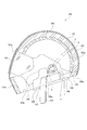
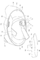
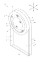
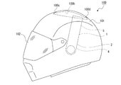
- FIG. 7 shows an embodiment of a speaker device according to an embodiment of the present technology, which is a side view of a helmet shown with a speaker device attached. It is a sectional view of a helmet shown with a speaker device attached. It is a perspective view of a helmet shown in the state where one cheek pad was removed and a speaker device was attached. It is an expansion perspective view of a speaker apparatus. It is an expanded sectional view of a speaker device.
- a procedure for attaching the speaker device to the helmet will be described with FIG. 7, and this figure is a side view showing a state before the cheek pad is attached. It is a side view showing a state where a cheek pad is attached and a speaker device is attached to a helmet.
- FIG. 6 is a side view showing an example of a speaker device in which a sound output direction from a rear surface of a speaker unit and a sound guiding direction of a duct are in the same direction.
- FIG. 11 is a side view showing another example of the speaker device in which the output direction of sound from the back surface of the speaker unit and the direction of guiding sound in the duct are the same.
- FIG. 6 is a side view showing an example of a speaker device in which an output direction of sound from a rear surface of a speaker unit and a direction of guiding sound in a duct are different from each other. It is a front view which shows the example of the speaker apparatus in which the front end surface of the duct was inclined.
- the helmet 100 is, for example, a helmet for a motorcycle such as a motorcycle, and includes a shell 101 provided as an exterior and each required part attached to or supported by the shell 101.
- the helmet 100 may be, for example, a helmet used at a construction site or the like, or another type of helmet used for disaster prevention or the like.
- the shell 101 is opened downward and has a window portion 101a on the front side.
- the shell 101 is formed of, for example, fiber reinforced resin.
- a transparent face cover 102 that opens and closes the window 101a is rotatably supported on the outer surface of the shell 101.
- a shock absorbing liner 103 is attached to the inner surface of the shell 101.
- the impact absorbing liner 103 is made of styrene foam and is composed of, for example, a main liner 103a and a front liner 103b.
- the main liner 103a is attached to a position extending from the upper part to the rear part of the shell 101, and the front liner 103b is attached to the lower part in the front part of the shell 101.
- the shock absorbing liner 103 is covered with a cloth cover (not shown).
- a head pad 104 is attached inside the shell 101 as an interior component.
- the head pad 104 is attached to the shell 101 by, for example, a hook stop or a fastener stop.
- the head pad 104 is formed mainly of a cushion material such as urethane foam, and has a function of receiving a head when the passenger is wearing the helmet 100.
- the head pad 104 is attached to the shell 101 so as to cover the main liner 103a from the inside.
- a neck pad 105 is attached as an interior component inside the shell 101.
- the neck pad 105 is attached to the shell 101 by, for example, a hook stop or a fastener stop.
- the neck pad 105 may be formed integrally with the head pad 104.
- the neck pad 105 is formed mainly of a cushion material such as urethane foam, and has a function of receiving a neck portion in a state where the helmet 100 is worn by a passenger.
- the neck pad 105 is formed in a substantially U-shape that is open to the front, and has a rear portion 105a located on the rear side and side portions 105b and 105b that are continuous with both left and right ends of the rear portion 105a.
- the neck pad 105 is attached to the shell 101 with the rear portion 105a positioned below the lower end of the main liner 103a and the lower end of the neck pad 104.
- the side portions 105b and 105b of the neck pad 105 are attached to the inner peripheral portion of the lower end portion of the shell 101 between the main liner 103a and the front liner 103b, respectively.
- Cheek pads 106, 106 are attached to the left and right sides of the inner surface of the shell 101 as interior parts.
- the cheek pad 106 is attached to the shell 101 by, for example, a hook stop or a fastener stop.
- the cheek pad 106 is formed mainly of a cushion material such as urethane foam, and has a function of receiving a cheek when the passenger is wearing the helmet 100.
- the cheek pad 106 includes a receiving surface portion 107 formed in a shape that extends in the left-right direction and extends substantially in the front-rear direction, and a bending surface portion 108 that is bendable in the left-right direction with respect to the receiving surface portion 107 and is continuous with the lower edge of the receiving surface portion 107.
- the receiving surface 107 has a projecting surface 109 that projects upward from a part of the upper edge of the receiving surface 107.
- a notch 106 a is formed in the cheek pad 106 between the receiving surface portion 107 and the projecting surface portion 109.
- the cheek pad 106 has a curved surface portion 108 bent substantially at a right angle to the receiving surface portion 107, and is attached to the shell 101, for example, with each portion of the curved surface portion 108 covering each portion of the neck pad 105 from below.
- the receiving surface portion 107 and the projecting surface portion 109 are located along the side portion on the inner surface of the shell 101.
- One end of the jaw belts 110, 110 is attached to the inner surface of the shell 101, and the jaw belts 110, 110 project downward from the lower opening 101b of the shell 101.
- the jaw belt 110 is inserted into the notch 106a of the cheek pad 106 and protrudes downward from the lower opening 101b of the shell 101 in a state where the cheek pad 106 is attached to a side portion on the inner surface of the shell 101.
- the other ends of the jaw belts 110, 110 are connected to each other, and the jaw belts 110, 110 are attached to the passenger's chin while the helmet 100 is attached to the passenger.
- the configuration of the helmet 100 described above is an example, and the shape, size and position of the shock absorbing liner 103, and the shape, size and position of the head pad 104, the neck pad 105 and the cheek pad 106 are different. Good. Further, as the interior parts of the helmet 100, only the head pad 104 and the cheek pad 106 may be provided.
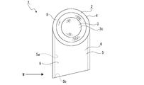
- the speaker device 1 is, for example, a dynamic speaker device, and has a case body 2 and a speaker unit 3 (see FIGS. 4 and 5).
- the case body 2 has a speaker housing 4 whose outer shape is formed into a substantially circular shape, and a duct 5 which is continuous with the speaker housing 4 and whose outer shape is formed into a substantially rectangular shape.
- the side portion and the back side portion are integrally formed.
- the speaker housing 4 and the duct 5 are integrally formed in the speaker device 1, there is no need to separately form the speaker housing 4 and the duct 5, and the speaker device 1 is It is possible to reduce the number of parts and the manufacturing cost.
- the speaker housing 4 and the duct 5 may be provided as separate members.
- the case body 2 is composed of a front case 6 and a rear case 7 joined together.
- the front case 6 side is the front side
- the rear case 7 side is the back side
- the front case 6 and the rear case 7 are coupled in the thickness direction.
- the front case 6 has a substantially annular holding portion 8 and a rectangular flat plate portion 9 continuous with the holding portion 8.
- the holding portion 8 is provided with a flange-shaped pressing portion 8a that projects inward from the front end portion.
- a circular space is formed inside the holding part 8a in the holding part 8, and this space is formed as a voice output hole 8b.
- the rear case 7 has a first connecting portion 10 connected to the holding portion 8 and a second connecting portion 11 connected to the flat plate portion 9.
- the first coupling portion 10 has a substantially circular back wall portion 10a and a peripheral surface portion 10b protruding from the outer peripheral portion of the rear wall portion 10a to the front side, and the front surface of the peripheral surface portion 10b.
- the end face on the side is abutted against the end face on the back side of the holding portion 8 and is joined to the holding portion 8.
- the speaker housing 4 is configured by coupling the holding portion 8 and the first coupling portion 10, and a space inside the speaker housing 4 is formed as an arrangement space 12.
- the second coupling portion 11 has a rectangular facing surface portion 11a and side surface portions 11b and 11b protruding from both side edges of the facing surface portion 11a to the front side, respectively, and the front end surfaces of the side surface portions 11b and 11b are flat plates.
- the flat plate portion 9 is joined to both side edges of the portion 9 by being abutted against each other.
- the flat plate portion 9 and the second coupling portion 11 are coupled to form the duct 5, and a part of the sound output from the speaker unit 3 is guided in the internal space 5a of the duct 5.
- the opening of the duct 5 on the side opposite to the speaker housing 4 is formed as a sound emission port 5b.
- the duct 5 is formed in a tubular shape extending in a direction orthogonal to the thickness direction of the speaker device 1, and the thickness direction T is smaller than the width direction H and the length direction L to be thin. Further, the speaker housing 4 has a thickness slightly larger than the thickness of the duct 5, but the thickness direction T is smaller than the width direction H and the length direction L to be thin. Therefore, the speaker device 1 is thin as a whole in which the thickness direction T is smaller than the width direction H and the length direction L.
- the speaker unit 3 is arranged in the speaker housing 4.
- the speaker unit 3 has a drive unit 3a having a coil and a magnet, a unit case 3b in which the drive unit 3a is arranged, and a diaphragm 3c supported by the unit case 3b on the front side of the drive unit 3a.
- the speaker unit 3 is arranged in the arrangement space 12 of the speaker housing 4 in a state where the axial direction is aligned with the thickness direction of the case body 2, the unit case 3b is held by the holding portion 8 from the outer peripheral side, and the diaphragm 3c outputs sound. Located in hole 8b.
- the unit case 3b and the back wall portion 10a of the first coupling portion 10 are positioned to face each other in the thickness direction of the case body 2, and the back surface of the speaker unit 3 is formed.
- a space is formed between the end surface on the side and the surface on the front side of the back wall portion 10a, and this space is the output space 12a.
- the output space 12a of the speaker housing 4 communicates with the internal space 5a of the duct 5.
- the distance A between the rear surface 3a of the speaker unit 3 which is the rear end surface of the unit case 3b and the front surface of the rear wall portion 10a is the distance of the internal space 5a of the duct 5 in the direction of guiding sound. It is smaller than B (see FIG. 5).
- a signal is input to the speaker unit 3 by wireless communication, for example, and sound is output according to the input signal.
- the speaker device 1 may be of a type in which a signal is input to the speaker unit 3 by wire.
- Audio is output from the speaker unit 3 to the front side through the audio output hole 8b. Further, in the speaker device 1, a part of the sound is output from the speaker unit 3 to the back side. The sound output to the back side passes through the output space 12a and the inner space 5a of the duct 5 inside the speaker housing 4 in order and is emitted to the outside of the speaker device 1 from the sound emission port 5b.
- the output direction P in which sound is output from the rear surface 3a of the speaker unit 3 and the direction Q in which sound is guided through the duct 5 are orthogonal to each other (see FIG. 5).
- the arrangement space 12 is not opened except for the sound output hole 8b, and the duct 5 is output to the rear side from the speaker unit 3 because the inner space 5a is not opened except the sound emission port 5b.
- the generated sound is not emitted to the outside of the speaker device 1 when passing through the output space 12a and the internal space 5a, but is emitted to the outside of the speaker device 1 only from the voice emission port 5b.
- the speaker devices 1 and 1 are attached to the left and right sides of the inner surface of the shell 101 with their fronts facing each other.
- the speaker device 1 is attached to the shell 101 by various means such as adhesion, attachment, engagement, and pressing by another member.
- the speaker device 1 is attached such that the back wall portion 10a of the case body 2 faces the inner surface of the shell 101, and the diaphragm 3c of the speaker unit 3 faces the ear.
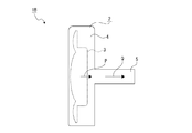
- the speaker device 1 is arranged on the inner surface of the shell 101 before the head pad 104 and the neck pad 105 are attached to the shell 101 and the cheek pad 106 is attached to the shell 101 (see FIG. 6 ). At this time, in the speaker device 1, the duct 5 is pressed against the side portion 105b of the neck pad 105.
- the cheek pad 106 is attached to the shell 101 so as to cover a part of the speaker device 1 from the inside (see FIG. 7).
- the duct 5 is pressed from the inside by the receiving surface portion 107 of the cheek pad 106 and sandwiched between the side portion 105b of the neck pad 105 and the receiving surface portion 107 of the cheek pad 106.
- the receiving surface portion 107 of the cheek pad 106 sandwiching the duct 5 and the side portion 105b of the neck pad 105 are in a deformed state.
- the duct 5 and the speaker housing 4 may be pressed from the inside by the receiving surface portion 107 of the cheek pad 106 as long as the output of the sound from the speaker unit 3 is not disturbed.
- the housing 4 may be pressed from the inside by the receiving surface portion 107 of the cheek pad 106.
- the speaker device 1 is attached to the helmet 100 by attaching the cheek pad 106 to the shell 101 as described above.
- the duct 5 is pressed by the receiving surface portion 107 of the cheek pad 106, and the holding portion 8 part of which protrudes toward the ear side from the duct 5 is located above the receiving surface portion 107. Is located.
- the receiving surface portion 107 can support the holding portion 8 from below, so that the speaker device 1 can be prevented from falling.
- the speaker device 1 may be attached to the helmet 100 by other means such as an adhesive tape.
- the speaker device 1 is attached to the helmet 100 with at least a part of the speaker housing 4 or the duct 5 being pressed by the cheek pad 106, at least one of the speaker housing 4 or the duct 5 is attached to the helmet 100. The portion is pressed by the cheek pad 106, and the speaker device 1 can be stably attached to the helmet 100.
- the speaker device 1 at least a part of the speaker housing 4 or the duct 5 is attached to the helmet 100 in a state of being sandwiched between the cheek pad 106 and other interior parts, for example, the neck pad 105.
- the speaker device 1 can be stably attached to the helmet 100. It is possible to prevent the speaker device 1 from being damaged or scratched.
- the sound output from the speaker unit 3 to the front side reaches the ear through the sound output hole 8b. Then, the sound output from the speaker unit 3 to the back side passes through the output space 12a of the speaker unit 3 and the internal space 5a of the duct 5 in order and is emitted to the outside of the speaker device 1 from the voice emission port 5b.
- the sound emission port 5b of the duct 5 is located below the speaker housing 4 (see FIG. 2).
- the sound output from the back surface 3a of the speaker unit 3 is emitted downward from the duct 5, so that the opening direction of the helmet 100 and the opening direction of the sound emitting port 5b are aligned, and the back surface 3a of the speaker unit 3 is aligned. It is possible to easily and reliably emit the sound output from the helmet 100 to the outside of the helmet 100.
- the sound emission port 5b is located above the lower opening 101b of the helmet 100.
- the duct 5 does not project outward from the lower opening 101b of the helmet 100, it is difficult for the outside air to enter from the sound emission port 5b, and for example, the generation of wind noise when the motorcycle is running is suppressed, and the speaker unit 3 is removed. It is possible to improve the quality of output voice.
- the speaker housing 4 is attached to the helmet 100 in a state of being positioned above the duct 5 in a state of being positioned above the duct 5 has been shown.
- the speaker device 1 has the helmet housing 4 in a position other than above the duct 5 in the helmet 100.
- the speaker housing 4 and the duct 5 may be attached to the helmet 100 in a state of being arranged front and rear or in a state of being arranged obliquely with respect to the vertical and horizontal directions.
- the speaker device 1 may be attached to the helmet 100 with the speaker housing 4 positioned on the front side of the duct 5 (see FIG. 8).
- the voice emission hole 100a is formed in the helmet 100, the internal space 5a of the duct 5 is communicated with the voice emission hole 100a, and the voice is emitted from the voice emission hole 100a to the outside of the helmet 100 via the voice emission port 5b. Is released.
- the voice emission hole 100a through which the internal space 5a of the duct 5 communicates is formed in the helmet 100, the voice output from the back surface 3a of the speaker unit 3 is transmitted from the voice emission hole 100a to the outside of the helmet 100. Since the sound is emitted, the sound output from the back surface 3a of the speaker unit 3 can be easily emitted to the outside of the helmet 100 with a simple configuration.
- the speaker housing 4 when the speaker housing 4 is attached to the helmet 100 in a state where the speaker housing 4 is located on the front side of the duct 5, the sound emission port 5b is located behind the speaker housing 4.
- the sound output from the rear surface 3a of the speaker unit 3 is emitted rearward from the duct 5, so that, for example, when the motorcycle or the like is traveling, it is difficult for the outside air to enter from the sound emission port 5b, and a wind noise is generated.
- the quality of the sound output from the speaker unit 3 can be suppressed, and the sound output from the back surface 3a of the speaker unit 3 can be easily emitted to the outside of the helmet 100.
- the speaker device 1 may be attached to the helmet 100 with the speaker housing 4 positioned below the duct 5, for example (see FIG. 9). Also in this case, the voice emitting hole 100a for emitting voice to the outside of the helmet 100 from the voice emitting port 5b is formed in the helmet 100.
- the helmet 100 there is a helmet 100 having a cooling space 100b formed in the upper part thereof and an air inflow hole 100c and an air outflow hole 100d communicating with the cooling space 100b.
- the outside air flows into the cooling space 100b from the air inflow hole 100c, and the space inside the helmet 100 is cooled by the air that has flowed into the cooling space 100b and is used for cooling.
- the air in the cooling space 100b flows out through the air outflow holes 100d. Therefore, the temperature rise in the space inside the helmet 100 is suppressed, and a good wearing state of the helmet 100 for the user is secured.
- the internal space 5a of the duct 5 can be connected to the cooling space 100b via the sound emission port 5b.
- the speaker housing 4 is positioned below the duct 5 so that the internal space 5a of the duct 5 communicates with the cooling space 100b.
- the sound output from the back surface 3a of the speaker unit 3 is emitted to the outside of the helmet 100 via the air outlet 100b and the air outlet 100d.
- the sound output from the back surface 3 a of the speaker unit 3 is emitted to the outside of the helmet 100 using the space formed in the helmet 100 in advance, and the sound output from the back surface 3 a of the speaker unit 3 is output to the helmet 100. It can be reliably released to the outside.
- the speaker device 1 in which the output direction P of the sound from the back surface 3a of the speaker unit 3 and the direction Q of guiding the sound of the duct 5 are orthogonal to each other is shown as an example (see FIG. 5).
- the output direction P of the sound from the back surface 3a of the speaker unit 3 and the direction Q of guiding the sound of the duct 5 may be the same direction (see FIGS. 10 and 11). ).
- the duct 5 is provided continuously to the back wall portion 10a of the speaker housing 4, and the sound output from the back surface 3a of the speaker unit 3 is guided to the back side by the duct 5 and the outside of the helmet 100 is guided from the back side. Is released to.
- the output direction P of the sound from the back surface 3a of the speaker unit 3 and the direction Q of guiding the sound of the duct 5 may be different directions although not orthogonal to each other (see FIG. 12).
- the direction in which the duct 5 extends is inclined with respect to the output direction P of the sound from the speaker unit 3.
- the sound from the rear surface 3a of the speaker unit 3 is The output direction P and the extending direction of the duct 5 are different directions, and the direction of the duct 5 with respect to the speaker housing 4 can be freely set.
- the degree of freedom in the shapes of the speaker housing 4 and the duct 5 is increased, the speaker device 1 can be downsized, and the space inside the helmet 100 can be effectively used.
- the sound from the rear surface 3a of the speaker unit 3 is The output direction P and the extending direction of the duct 5 are orthogonal to each other.
- the speaker device 1 can be made thinner, and the space inside the helmet 100 can be effectively utilized. Can be planned.
- the distance of the inner space 5a of the duct 5 in the direction of guiding the sound be made smaller toward the rear of the helmet 100 (see FIG. 13).
- the vertical length of the duct 5 is shortened toward the rear, and the sound emission port 5b is slanted downward and rearward. Is turned to face.
- the distance of the internal space 5a in the direction in which the sound of the duct 5 is guided is made smaller toward the rear of the helmet 100, so that, for example, when the motorcycle or the like is traveling, the direction of the sound emission port 5b is directed toward the speaker device 1. Since it is not directed to the wind W flowing from the front, it is difficult for the outside air to invade from the sound emission port 5b, the generation of wind noise is suppressed, and the quality of the sound output from the speaker unit 3 can be improved. it can.
- the duct 5 is inclined with respect to the speaker housing 4 so that the sound emission port 5b does not face the wind W flowing from the front toward the speaker device 1,
- the generation of wind noise may be suppressed by making it difficult for the outside air to enter through the discharge port 5b.
- the rear wall portion 10a that covers the speaker unit 3 from the rear side is provided, and the space between the rear surface 3a of the speaker unit 3 and the rear wall portion 10a.
- the speaker housing 4 formed as an output space 12a of the sound output from the back surface 3a of the speaker unit 3 and the sound output from the output space 12a to the outside of the helmet 100 by communicating the internal space 5a with the output space 12a. And a duct 5 that guides it.
- Helmet 100 is often used in construction sites and disaster prevention applications, so it is often subject to shocks, and because it is also used when driving a motorcycle or other motorcycle, it is often subject to vibration.
- the speaker devices 1, 1A, 1B, and 1C holes or cutouts are not formed in the speaker housing 4 and the duct 5 in the path from the back surface 3a of the speaker unit 3 to the sound emission port 5b, and High strength of the housing 4 and the duct 5 is ensured. Therefore, even if shock or vibration is applied to the helmet 100, mechanical damage is unlikely to occur in the speaker devices 1, 1A, 1B, and 1C, and the speaker devices 1, 1A, 1B, and 1C can be used well due to the improved strength. The state can be secured.
- the distance A between the back surface 3a of the speaker unit 3 and the back wall portion 10a is made smaller than the distance B of the internal space 5a of the duct 5 in the direction of guiding sound. ing.
- the speaker housing 4 can be thinned, and the speaker housing 4 can be thinned to reduce the space for disposing the speaker devices 1, 1A, 1B, and 1C inside the helmet 100. it can.
- the sound output from the back surface 3a of the speaker unit 3 passes through the output space 12a and the internal space 5a and is emitted to the outside of the helmet 100 from the voice emission port 5b.
- the sound output from the speaker unit 3 to the front side does not mix with the sound output from the speaker unit 3 to the back side, and the sounds output from the speaker unit 3 to the front side and the back side are opposite to each other. Since they do not cancel each other out as the voices of the phase, it is possible to suppress the decrease of the sound pressure sensitivity in the low range.
- the present technology may have the following configurations.
- a speaker unit that outputs audio A speaker housing having a back wall portion covering the speaker unit from the back side, wherein a space between the back surface of the speaker unit and the back wall portion is formed as an output space for sound output from the back surface of the speaker unit; An interior space is connected to the output space, and a duct for guiding the sound output to the output space to the outside of the helmet is provided, A speaker device in which the distance between the back surface of the speaker unit and the back wall portion is smaller than the distance of the internal space of the duct in the direction of guiding sound.
- An opening at the tip of the duct is formed as a sound emission port for emitting sound to the outside of the helmet,
- the speaker device according to any one of (1) to (4), wherein the sound emission port is located below the speaker housing in a state of being attached to the helmet.
- An opening at the tip of the duct is formed as a sound emission port for emitting sound to the outside of the helmet,
- the speaker device according to any one of (1) to (4), wherein the sound emission port is located rearward of the speaker housing in a state of being attached to the helmet.
- a cooling space is formed inside the helmet and the helmet is formed with a wind inflow hole and a wind outflow hole which are in communication with the cooling space,
- the speaker device according to any one of (1) to (4), wherein the internal space communicates with the cooling space.
- a voice emission hole is formed in the helmet, The speaker device according to any one of (1) to (9), wherein the internal space communicates with the sound emitting hole.
- the helmet has a cheek pad provided as an interior component,
- the speaker device according to any one of (1) to (10), wherein at least a part of the speaker housing or the duct is attached to the helmet while being pressed by the cheek pad.
Landscapes
- Physics & Mathematics (AREA)
- Engineering & Computer Science (AREA)
- Acoustics & Sound (AREA)
- Signal Processing (AREA)
- Health & Medical Sciences (AREA)
- Otolaryngology (AREA)
- Helmets And Other Head Coverings (AREA)
- Fittings On The Vehicle Exterior For Carrying Loads, And Devices For Holding Or Mounting Articles (AREA)
- Soundproofing, Sound Blocking, And Sound Damping (AREA)
Abstract
Description
先ず、スピーカー装置1が取り付けられるヘルメット100の構成について説明する(図1乃至図3参照)。
次に、ヘルメット100に取り付けられるスピーカー1の構成について説明する(図4及び図5参照)。
次いで、スピーカー装置1のヘルメット100への取付状態について説明する(図2、図3、図6及び図7参照)。
以下に、スピーカー装置1のヘルメット100への他の取付状態について説明する(図8及び図9参照)。
上記には、スピーカーユニット3の背面3aからの音声の出力方向Pとダクト5の音声を導く方向Qとが直交する方向にされたスピーカー装置1を例として示した(図5参照)。但し、スピーカー装置1A、1Bのように、スピーカーユニット3の背面3aからの音声の出力方向Pとダクト5の音声を導く方向Qとが同じ方向にされていてもよい(図10及び図11参照)。
以上に記載した通り、スピーカー装置1、1A、1B、1Cにあっては、スピーカーユニット3を背面側から覆う背面壁部10aを有しスピーカーユニット3の背面3aと背面壁部10aの間の空間がスピーカーユニット3の背面3aから出力される音声の出力空間12aとして形成されたスピーカーハウジング4と、内部空間5aが出力空間12aに連通され出力空間12aに出力される音声をヘルメット100の外部へ向けて導くダクト5とを備えている。
本技術は、以下のような構成にすることができる。
ヘルメットに取り付けられた状態で使用され、
音声の出力を行うスピーカーユニットと、
前記スピーカーユニットを背面側から覆う背面壁部を有し前記スピーカーユニットの背面と前記背面壁部の間の空間が前記スピーカーユニットの背面から出力される音声の出力空間として形成されたスピーカーハウジングと、
内部空間が前記出力空間に連通され前記出力空間に出力される音声を前記ヘルメットの外部へ向けて導くダクトとを備え、
前記スピーカーユニットの背面と前記背面壁部の間の距離が音声を導く方向における前記ダクトの内部空間の距離より小さくされた
スピーカー装置。
前記スピーカーハウジングの少なくとも一部と前記ダクトの少なくとも一部とが一体に形成された
前記(1)に記載のスピーカー装置。
前記スピーカーユニットの背面からの音声の出力方向と前記ダクトの音声を導く方向とが異なる方向にされた
前記(1)又は前記(2)に記載のスピーカー装置。
前記スピーカーユニットの背面からの音声の出力方向と前記ダクトの音声を導く方向とが直交する方向にされた
前記(3)に記載のスピーカー装置。
前記ダクトにおける先端の開口が音声を前記ヘルメットの外部に放出する音声放出口として形成され、
前記ヘルメットに取り付けられた状態において前記音声放出口が前記スピーカーハウジングより下方に位置された
前記(1)から前記(4)の何れかに記載のスピーカー装置。
前記音声放出口が前記ヘルメットの下側開口より上側に位置された
前記(5)に記載のスピーカー装置。
前記ダクトは音声を導く方向における内部空間の距離が前記ヘルメットの後方へ行くに従って小さくされた
前記(5)又は前記(6)に記載のスピーカー装置。
前記ダクトにおける先端の開口が音声を前記ヘルメットの外部に放出する音声放出口として形成され、
前記ヘルメットに取り付けられた状態において前記音声放出口が前記スピーカーハウジングより後方に位置された
前記(1)から前記(4)の何れかに記載のスピーカー装置。
前記ヘルメットの内部に冷却用空間が形成されると共に前記ヘルメットには前記冷却用空間に連通された風流入孔と風流出孔が形成され、
前記内部空間が前記冷却用空間に連通された
前記(1)から前記(4)の何れかに記載のスピーカー装置。
前記ヘルメットに音声放出孔が形成され、
前記内部空間が前記音声放出孔に連通された
前記(1)から前記(9)の何れかに記載のスピーカー装置。
前記ヘルメットは内装部品として設けられたチークパッドを有し、
前記スピーカーハウジング又は前記ダクトの少なくとも一部が前記チークパッドに押さえられた状態で前記ヘルメットに取り付けられた
前記(1)から前記(10)の何れかに記載のスピーカー装置。
前記スピーカーハウジング又は前記ダクトの少なくとも一部が前記チークパッドと他の前記内装部品とに挟まれた状態で前記ヘルメットに取り付けられた
前記(11)に記載のスピーカー装置。
Claims (12)
- ヘルメットに取り付けられた状態で使用され、
音声の出力を行うスピーカーユニットと、
前記スピーカーユニットを背面側から覆う背面壁部を有し前記スピーカーユニットの背面と前記背面壁部の間の空間が前記スピーカーユニットの背面から出力される音声の出力空間として形成されたスピーカーハウジングと、
内部空間が前記出力空間に連通され前記出力空間に出力される音声を前記ヘルメットの外部へ向けて導くダクトとを備え、
前記スピーカーユニットの背面と前記背面壁部の間の距離が音声を導く方向における前記ダクトの内部空間の距離より小さくされた
スピーカー装置。 - 前記スピーカーハウジングの少なくとも一部と前記ダクトの少なくとも一部とが一体に形成された
請求項1に記載のスピーカー装置。 - 前記スピーカーユニットの背面からの音声の出力方向と前記ダクトの音声を導く方向とが異なる方向にされた
請求項1に記載のスピーカー装置。 - 前記スピーカーユニットの背面からの音声の出力方向と前記ダクトの音声を導く方向とが直交する方向にされた
請求項3に記載のスピーカー装置。 - 前記ダクトにおける先端の開口が音声を前記ヘルメットの外部に放出する音声放出口として形成され、
前記ヘルメットに取り付けられた状態において前記音声放出口が前記スピーカーハウジングより下方に位置された
請求項1に記載のスピーカー装置。 - 前記音声放出口が前記ヘルメットの下側開口より上側に位置された
請求項5に記載のスピーカー装置。 - 前記ダクトは音声を導く方向における内部空間の距離が前記ヘルメットの後方へ行くに従って小さくされた
請求項5に記載のスピーカー装置。 - 前記ダクトにおける先端の開口が音声を前記ヘルメットの外部に放出する音声放出口として形成され、
前記ヘルメットに取り付けられた状態において前記音声放出口が前記スピーカーハウジングより後方に位置された
請求項1に記載のスピーカー装置。 - 前記ヘルメットの内部に冷却用空間が形成されると共に前記ヘルメットには前記冷却用空間に連通された風流入孔と風流出孔が形成され、
前記内部空間が前記冷却用空間に連通された
請求項1に記載のスピーカー装置。 - 前記ヘルメットに音声放出孔が形成され、
前記内部空間が前記音声放出孔に連通された
請求項1に記載のスピーカー装置。 - 前記ヘルメットは内装部品として設けられたチークパッドを有し、
前記スピーカーハウジング又は前記ダクトの少なくとも一部が前記チークパッドに押さえられた状態で前記ヘルメットに取り付けられた
請求項1に記載のスピーカー装置。 - 前記スピーカーハウジング又は前記ダクトの少なくとも一部が前記チークパッドと他の前記内装部品とに挟まれた状態で前記ヘルメットに取り付けられた
請求項11に記載のスピーカー装置。
Priority Applications (3)
| Application Number | Priority Date | Filing Date | Title |
|---|---|---|---|
| US17/309,573 US11750959B2 (en) | 2018-12-14 | 2019-11-06 | Speaker device |
| CN201980080341.5A CN113170248A (zh) | 2018-12-14 | 2019-11-06 | 扬声器装置 |
| KR1020217016567A KR20210102226A (ko) | 2018-12-14 | 2019-11-06 | 스피커 장치 |
Applications Claiming Priority (2)
| Application Number | Priority Date | Filing Date | Title |
|---|---|---|---|
| JP2018-234122 | 2018-12-14 | ||
| JP2018234122 | 2018-12-14 |
Publications (1)
| Publication Number | Publication Date |
|---|---|
| WO2020121692A1 true WO2020121692A1 (ja) | 2020-06-18 |
Family
ID=71075472
Family Applications (1)
| Application Number | Title | Priority Date | Filing Date |
|---|---|---|---|
| PCT/JP2019/043466 Ceased WO2020121692A1 (ja) | 2018-12-14 | 2019-11-06 | スピーカー装置 |
Country Status (4)
| Country | Link |
|---|---|
| US (1) | US11750959B2 (ja) |
| KR (1) | KR20210102226A (ja) |
| CN (1) | CN113170248A (ja) |
| WO (1) | WO2020121692A1 (ja) |
Cited By (1)
| Publication number | Priority date | Publication date | Assignee | Title |
|---|---|---|---|---|
| JP2023008473A (ja) * | 2021-07-06 | 2023-01-19 | 株式会社あおごち | ヘルメット用通話装置 |
Families Citing this family (1)
| Publication number | Priority date | Publication date | Assignee | Title |
|---|---|---|---|---|
| DE102024101164A1 (de) * | 2024-01-16 | 2025-07-17 | Audi Aktiengesellschaft | Verfahren zum Betrieb eines Kraftfahrzeugs, Kraftfahrzeug sowie Computerprogrammprodukt |
Citations (6)
| Publication number | Priority date | Publication date | Assignee | Title |
|---|---|---|---|---|
| JPS57160283U (ja) * | 1981-04-02 | 1982-10-07 | ||
| JPS59169320U (ja) * | 1983-04-28 | 1984-11-13 | パイオニア株式会社 | ヘルメツト |
| JPH01221504A (ja) * | 1988-02-28 | 1989-09-05 | Honda Motor Co Ltd | ヘルメットの音響装置 |
| US4977975A (en) * | 1989-09-14 | 1990-12-18 | Lazzeroni John J | Vented motorcycle helmet speaker enclosure |
| JPH04227396A (ja) * | 1991-05-16 | 1992-08-17 | Sony Corp | インナーイヤー型ヘッドホン |
| JP2005163222A (ja) * | 2003-12-02 | 2005-06-23 | Yamaha Motor Co Ltd | ヘルメット |
Family Cites Families (4)
| Publication number | Priority date | Publication date | Assignee | Title |
|---|---|---|---|---|
| JP4290315B2 (ja) | 2000-04-27 | 2009-07-01 | フォスター電機株式会社 | ヘッドホン・ユニット |
| US7308108B2 (en) * | 2004-04-10 | 2007-12-11 | Davis William E | Helmet-mounted intercommunications and entertainment system |
| DE102016103477A1 (de) * | 2016-02-26 | 2017-08-31 | USound GmbH | Audiosystem mit strahlformenden Lautsprechern sowie Brille mit einem derartigen Audiosystem |
| US10555071B2 (en) * | 2018-01-31 | 2020-02-04 | Bose Corporation | Eyeglass headphones |
-
2019
- 2019-11-06 CN CN201980080341.5A patent/CN113170248A/zh not_active Withdrawn
- 2019-11-06 US US17/309,573 patent/US11750959B2/en active Active
- 2019-11-06 KR KR1020217016567A patent/KR20210102226A/ko not_active Withdrawn
- 2019-11-06 WO PCT/JP2019/043466 patent/WO2020121692A1/ja not_active Ceased
Patent Citations (6)
| Publication number | Priority date | Publication date | Assignee | Title |
|---|---|---|---|---|
| JPS57160283U (ja) * | 1981-04-02 | 1982-10-07 | ||
| JPS59169320U (ja) * | 1983-04-28 | 1984-11-13 | パイオニア株式会社 | ヘルメツト |
| JPH01221504A (ja) * | 1988-02-28 | 1989-09-05 | Honda Motor Co Ltd | ヘルメットの音響装置 |
| US4977975A (en) * | 1989-09-14 | 1990-12-18 | Lazzeroni John J | Vented motorcycle helmet speaker enclosure |
| JPH04227396A (ja) * | 1991-05-16 | 1992-08-17 | Sony Corp | インナーイヤー型ヘッドホン |
| JP2005163222A (ja) * | 2003-12-02 | 2005-06-23 | Yamaha Motor Co Ltd | ヘルメット |
Cited By (2)
| Publication number | Priority date | Publication date | Assignee | Title |
|---|---|---|---|---|
| JP2023008473A (ja) * | 2021-07-06 | 2023-01-19 | 株式会社あおごち | ヘルメット用通話装置 |
| JP7656275B2 (ja) | 2021-07-06 | 2025-04-03 | 株式会社あおごち | ヘルメット用通話装置 |
Also Published As
| Publication number | Publication date |
|---|---|
| US11750959B2 (en) | 2023-09-05 |
| CN113170248A (zh) | 2021-07-23 |
| KR20210102226A (ko) | 2021-08-19 |
| US20220021957A1 (en) | 2022-01-20 |
Similar Documents
| Publication | Publication Date | Title |
|---|---|---|
| JP5671929B2 (ja) | イヤホン、音響変換装置 | |
| KR101827669B1 (ko) | 스피커 모듈 | |
| US8737665B2 (en) | Negative pressure earphone | |
| JPWO2005015947A1 (ja) | ディフューザ及びこれを用いたスピーカ | |
| US10645478B2 (en) | In-ear headphone for improved fit and function, and related methods | |
| WO2020034727A1 (zh) | 发声装置 | |
| WO2020121692A1 (ja) | スピーカー装置 | |
| US11206477B2 (en) | Sound transducer structure of electronic device | |
| WO2020034728A1 (zh) | 终端装置 | |
| JP4962221B2 (ja) | ヘッドホン | |
| CN211296899U (zh) | 表体和可穿戴设备 | |
| US7450976B2 (en) | Portable electronic device | |
| JP7618141B2 (ja) | 音響装置付きヘルメット、ヘルメットと前記ヘルメットに装着される音響装置の組合せ及びヘルメットと前記ヘルメットに装着される音響装置に用いられる加振型音響ユニットの組合せ | |
| JP4290315B2 (ja) | ヘッドホン・ユニット | |
| JP2012116244A (ja) | 車両用ドア構造 | |
| CN115623398B (zh) | 电子设备 | |
| JP6952386B1 (ja) | 車両のスピーカ装置及び部屋のスピーカ装置 | |
| JP2004343548A (ja) | バスレフ型スピーカ装置及び該バスレフ型スピーカ装置を内蔵した映像表示装置 | |
| WO2001091509A1 (en) | Speaker using helmet as component and helmet having speaker function | |
| KR102002529B1 (ko) | 노즐 일체형 스피커유닛을 구비한 이어폰 | |
| EP3944630B1 (en) | Vehicle-mounted device | |
| KR102484202B1 (ko) | 헤드셋 장치 | |
| CN216253160U (zh) | 头部音箱组件及机器人 | |
| US20260060360A1 (en) | Speaker system for a helmet | |
| US11102587B2 (en) | Hybrid acoustic apparatus including rectangular microspeaker |
Legal Events
| Date | Code | Title | Description |
|---|---|---|---|
| 121 | Ep: the epo has been informed by wipo that ep was designated in this application |
Ref document number: 19894858 Country of ref document: EP Kind code of ref document: A1 |
|
| ENP | Entry into the national phase |
Ref document number: 20217016567 Country of ref document: KR Kind code of ref document: A |
|
| NENP | Non-entry into the national phase |
Ref country code: DE |
|
| 122 | Ep: pct application non-entry in european phase |
Ref document number: 19894858 Country of ref document: EP Kind code of ref document: A1 |
|
| NENP | Non-entry into the national phase |
Ref country code: JP |