WO2020121726A1 - Automate d'analyse - Google Patents
Automate d'analyse Download PDFInfo
- Publication number
- WO2020121726A1 WO2020121726A1 PCT/JP2019/044679 JP2019044679W WO2020121726A1 WO 2020121726 A1 WO2020121726 A1 WO 2020121726A1 JP 2019044679 W JP2019044679 W JP 2019044679W WO 2020121726 A1 WO2020121726 A1 WO 2020121726A1
- Authority
- WO
- WIPO (PCT)
- Prior art keywords
- rack
- cleaning
- analysis unit
- analysis
- sample
- Prior art date
- Legal status (The legal status is an assumption and is not a legal conclusion. Google has not performed a legal analysis and makes no representation as to the accuracy of the status listed.)
- Ceased
Links
Images


Classifications
-
- G—PHYSICS
- G01—MEASURING; TESTING
- G01N—INVESTIGATING OR ANALYSING MATERIALS BY DETERMINING THEIR CHEMICAL OR PHYSICAL PROPERTIES
- G01N35/00—Automatic analysis not limited to methods or materials provided for in any single one of groups G01N1/00 - G01N33/00; Handling materials therefor
- G01N35/00584—Control arrangements for automatic analysers
- G01N35/00594—Quality control, including calibration or testing of components of the analyser
- G01N35/00693—Calibration
-
- G—PHYSICS
- G01—MEASURING; TESTING
- G01N—INVESTIGATING OR ANALYSING MATERIALS BY DETERMINING THEIR CHEMICAL OR PHYSICAL PROPERTIES
- G01N35/00—Automatic analysis not limited to methods or materials provided for in any single one of groups G01N1/00 - G01N33/00; Handling materials therefor
- G01N35/00584—Control arrangements for automatic analysers
- G01N35/00594—Quality control, including calibration or testing of components of the analyser
- G01N35/00613—Quality control
- G01N35/00623—Quality control of instruments
-
- G—PHYSICS
- G01—MEASURING; TESTING
- G01N—INVESTIGATING OR ANALYSING MATERIALS BY DETERMINING THEIR CHEMICAL OR PHYSICAL PROPERTIES
- G01N35/00—Automatic analysis not limited to methods or materials provided for in any single one of groups G01N1/00 - G01N33/00; Handling materials therefor
- G01N35/02—Automatic analysis not limited to methods or materials provided for in any single one of groups G01N1/00 - G01N33/00; Handling materials therefor using a plurality of sample containers moved by a conveyor system past one or more treatment or analysis stations
- G01N35/04—Details of the conveyor system
-
- G—PHYSICS
- G01—MEASURING; TESTING
- G01N—INVESTIGATING OR ANALYSING MATERIALS BY DETERMINING THEIR CHEMICAL OR PHYSICAL PROPERTIES
- G01N35/00—Automatic analysis not limited to methods or materials provided for in any single one of groups G01N1/00 - G01N33/00; Handling materials therefor
- G01N2035/00178—Special arrangements of analysers
- G01N2035/00326—Analysers with modular structure
-
- G—PHYSICS
- G01—MEASURING; TESTING
- G01N—INVESTIGATING OR ANALYSING MATERIALS BY DETERMINING THEIR CHEMICAL OR PHYSICAL PROPERTIES
- G01N35/00—Automatic analysis not limited to methods or materials provided for in any single one of groups G01N1/00 - G01N33/00; Handling materials therefor
- G01N35/00584—Control arrangements for automatic analysers
- G01N35/00722—Communications; Identification
- G01N2035/00891—Displaying information to the operator
-
- G—PHYSICS
- G01—MEASURING; TESTING
- G01N—INVESTIGATING OR ANALYSING MATERIALS BY DETERMINING THEIR CHEMICAL OR PHYSICAL PROPERTIES
- G01N35/00—Automatic analysis not limited to methods or materials provided for in any single one of groups G01N1/00 - G01N33/00; Handling materials therefor
- G01N35/02—Automatic analysis not limited to methods or materials provided for in any single one of groups G01N1/00 - G01N33/00; Handling materials therefor using a plurality of sample containers moved by a conveyor system past one or more treatment or analysis stations
- G01N35/04—Details of the conveyor system
- G01N2035/0401—Sample carriers, cuvettes or reaction vessels
- G01N2035/0412—Block or rack elements with a single row of samples
-
- G—PHYSICS
- G01—MEASURING; TESTING
- G01N—INVESTIGATING OR ANALYSING MATERIALS BY DETERMINING THEIR CHEMICAL OR PHYSICAL PROPERTIES
- G01N35/00—Automatic analysis not limited to methods or materials provided for in any single one of groups G01N1/00 - G01N33/00; Handling materials therefor
- G01N35/02—Automatic analysis not limited to methods or materials provided for in any single one of groups G01N1/00 - G01N33/00; Handling materials therefor using a plurality of sample containers moved by a conveyor system past one or more treatment or analysis stations
- G01N35/04—Details of the conveyor system
- G01N2035/0401—Sample carriers, cuvettes or reaction vessels
- G01N2035/0437—Cleaning cuvettes or reaction vessels
-
- G—PHYSICS
- G01—MEASURING; TESTING
- G01N—INVESTIGATING OR ANALYSING MATERIALS BY DETERMINING THEIR CHEMICAL OR PHYSICAL PROPERTIES
- G01N35/00—Automatic analysis not limited to methods or materials provided for in any single one of groups G01N1/00 - G01N33/00; Handling materials therefor
- G01N35/02—Automatic analysis not limited to methods or materials provided for in any single one of groups G01N1/00 - G01N33/00; Handling materials therefor using a plurality of sample containers moved by a conveyor system past one or more treatment or analysis stations
- G01N35/026—Automatic analysis not limited to methods or materials provided for in any single one of groups G01N1/00 - G01N33/00; Handling materials therefor using a plurality of sample containers moved by a conveyor system past one or more treatment or analysis stations having blocks or racks of reaction cells or cuvettes
-
- G—PHYSICS
- G01—MEASURING; TESTING
- G01N—INVESTIGATING OR ANALYSING MATERIALS BY DETERMINING THEIR CHEMICAL OR PHYSICAL PROPERTIES
- G01N35/00—Automatic analysis not limited to methods or materials provided for in any single one of groups G01N1/00 - G01N33/00; Handling materials therefor
- G01N35/10—Devices for transferring samples or any liquids to, in, or from, the analysis apparatus, e.g. suction devices, injection devices
- G01N35/1004—Cleaning sample transfer devices
Definitions
- the present invention relates to an automatic analyzer for performing qualitative/quantitative analysis of biological samples such as blood and urine.
- cleaning the mechanical parts related to analysis on a regular basis can be mentioned.
- Various cleaning methods have been proposed, but as one of the methods, the cleaning liquid necessary for cleaning is filled in a sample container, and the sample container is erected on a sample rack and transferred to an automatic analyzer.
- the rack is referred to as a cleaning rack.
- the cleaning effect removes various components, including dirt, that had adhered to the sample dispensing probe.
- the condition of the sample dispensing probe is improved, but the condition of the sample dispensing probe is different from that before maintenance.
- the measurement results may be affected before and after cleaning maintenance.
- the cleaning liquid used during cleaning may remain on the sample dispensing probe, which may affect the measurement results.
- cleaning using a cleaning rack is an important maintenance in order to keep the equipment condition constant, and it is required to perform it according to the equipment recommended period.
- the maintenance by the washing rack requires the user's preparation operation, so the user may neglect to carry out this maintenance.
- the cleaning of necessary parts is not performed within the recommended period of the device, and there is a concern that the condition of the device will deteriorate.
- Patent Document 1 discloses a calibration necessity determination means for determining whether or not calibration of a calibration curve of an analysis item is necessary based on the analysis parameter when the analysis parameter used for measurement is set.
- the calibration necessity determination means sets the calibration invalid flag of the analysis item determined to require calibration of the calibration curve, and the analysis for the analysis item is not performed.
- Patent Document 2 discloses a technique for automatically recommending a recalibration setting request for the analysis item due to a change in the index (parameter) that affects the calibration curve data. Specifically, when the index (parameter) is changed, the presence or absence of the corresponding calibration curve data is checked to determine the necessity of recalibration, and it is stored in the device as recalibration recommended information, Prompt the user to perform calibration measurement again.
- Patent Document 3 if the pipette of the dispensing unit is washed, an accurate analysis result may not be obtained due to contamination, and “the pipette was washed” may include an uncertainty factor. Therefore, in order to reduce the uncertainty due to pipette cleaning, the technology of registering the information “Please check the measurement result/quality control result before and after pipette cleaning” in the “uncertainty information database DB301” is disclosed. ..
- the re-calibration of the instrument and the measurement of the quality control sample by performing the calibration again in the instrument environment where the instrument condition has changed due to the maintenance A method of reconfirming the performance of the device by doing so can be considered.
- the washing operation is performed by loading the rack into the automatic analyzer, so the washing operation can be performed even during the routine analysis.
- the routine analysis is continued and calibration is not performed. It is possible that it is affecting.
- Patent Document 3 prompts the user to confirm the measurement result and the quality control result when there is a possibility of contamination due to cleaning, but the device condition may change. Even after washing with a certain washing rack, the user cannot recognize this mutation during the routine analysis, so the routine analysis is continued and calibration is not performed, which may affect the measurement results. ..
- An object of the present invention is to realize an automatic analyzer capable of maintaining a normal condition of the apparatus and exhibiting stable performance by automatically monitoring the cleaning execution status using a cleaning rack. ..
- the present invention is configured as follows to achieve the above object.
- At least one analysis unit for analyzing a sample at least, a rack loading unit into which a sample rack holding a sample and a washing rack holding a cleaning liquid are loaded, and the rack loading unit, the loading is performed.
- a transport mechanism that transports the sample rack and the washing rack to the analysis unit and an overall management control unit that controls operations of the analysis unit, the rack loading unit, and the transport mechanism, the overall management control Section transfers the cleaning rack to the analysis section, and the cleaning operation of the analysis section to which the cleaning rack is transferred by the cleaning liquid held in the cleaning rack, calibration analysis and measurement of a quality control sample in the analysis section.
- FIG. 1 is a system block diagram showing an overall schematic configuration of an automatic analyzer to which Example 1 is applied. It is a schematic top view of a biochemical unit. It is a schematic top view of an electrolyte analysis unit. It is a figure which shows the process flow of apparatus performance confirmation accompanying execution of a washing rack. It is a figure which shows the procedure flow in case the washing operation by a washing rack is not completed normally.
- FIG. 8 is a diagram showing a procedure of monitoring the cleaning implementation status by the cleaning rack according to the second embodiment. It is a figure which shows the example of a screen of the display part which can change a maintenance implementation period. It is a figure which shows the processing flow which wash-controls with a washing rack using the number of measurement tests (analysis number).
- FIG. 10 is a diagram showing a flowchart showing means for optimizing the transport of the washing rack according to the analysis implementation status in the automatic analyzer in the third embodiment. It is a figure which shows the conveyance processing flow of the washing rack, the calibration rack, and the quality control rack in Example 4. It is a figure which shows the processing flow which automatically produces
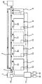
- FIG. 1 is a system block diagram showing the overall schematic configuration of an automatic analyzer to which the first embodiment of the present invention is applied.
- the analysis system to which the first embodiment is applied includes a sample rack loading section (rack loading section) 1, an ID reading section 2, a transport line (transport mechanism) 3, and analysis units 5, 6, and 7. And 8, a sample rack standby unit 9, a sample rack collection unit 10, and a computer for overall management (overall management control unit) 11.
- a sample rack holding a sample, a washing rack holding a washing solution, a calibration rack holding a standard solution, or a quality control rack holding quality control data is loaded in the sample rack loading unit 1.
- the analysis units 5, 6, 7, and 8 are also provided with control computers 12, 13, 14, and 15 for controlling necessary processing in each analysis unit.
- the sample rack loading section 1 is a part for loading a plurality of racks each holding one or a plurality of samples (samples).
- the transport of the sample rack from the transport line 3 to the analysis units 5, 6, 7, and 8 is performed by pulling the sample rack into the drop lines (pull-in mechanisms) 51, 61, 71, and 81, respectively.
- the sample rack loading unit 1 includes a control computer 16.
- An operation unit 18 and a display unit 19 are connected to the overall management computer 11.
- the analysis units 5, 6, 7, and 8 are arranged along the transfer line 3 and are detachably connected to the transfer line 3.
- the number of analysis units (analysis units) may be arbitrary, and the first embodiment shows a case of four.
- the case where the analysis units 5, 6, 7, and 8 are biochemical analysis units (biochemical analysis unit) or electrolyte analysis units (electrolyte analysis unit) will be described as an example.
- the configuration of the analysis units 5, 6, 7, and 8 may be a configuration including an immune analysis unit (immunological analysis unit), a configuration that is all biochemical analysis units, or a configuration that is all electrolyte analysis units.
- an immune analysis unit immunological analysis unit
- biochemical analysis units a configuration that is all biochemical analysis units
- electrolyte analysis units a configuration that is all electrolyte analysis units.
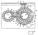
- FIG. 2 is a schematic top view of one biochemical unit of the analysis units 5, 6, 7, and 8.
- reaction vessels 35 are lined up on the circumference of the reaction disk 36 on the housing 62.
- the reagent disk 42 is arranged inside the reaction disk 36, and the reagent disk 41 is arranged outside.
- a plurality of reagent containers 40 can be placed on the circumference of each of the reagent disks 41 and 42. Two reagents are contained in one reagent container 40.
- a transfer line 3 for moving a sample rack 92 on which a sample container 91 is placed is installed near the reaction disk 36.
- Rails 25 and 26 are arranged on the reagent disc 41 and the reagent disc 42, and reagent dispensing probes 20 and 21 that are movable in a direction parallel to the rails and in the vertical direction are installed on the rail 25.
- reagent dispensing probes 22 and 23 that are movable in the three axis directions.
- the sample container 91 may be a container for storing the standard solution
- the sample rack 92 may be a calibration rack on which a container for storing the standard solution is placed.
- sample container 91 may be a container for storing the quality control sample
- sample rack 92 may be a quality control rack on which a container for storing the quality control sample is placed.
- Each of the reagent dispensing probes 20, 21, 22, 23 is connected to a reagent pump not shown in the figure. Between the reaction container 35 and the transfer line 33, sample dispensing probes 94 and 95 which can rotate and move up and down are installed. The sample dispensing probes 94 and 95 are each connected to a sample pump not shown in the drawing.
- the container cleaning mechanism 45 is connected to a cleaning pump not shown in the drawing.
- a washing port 54 is installed in each operating range of the sample dispensing probes 94, 95, the reagent dispensing probes 20, 21, 22, 23, and the stirring devices 30, 31.
- a replenishing reagent storage (not shown) is installed on the reagent disc 41.
- a plurality of reagent containers 40 can be mounted in the replenishing reagent storage.
- a sample pump, a reagent pump, a washing pump, a detection optical device 51, a reaction container 35, a reagent disc 41, reagent dispensing probes 20, 21, 22, 23, a sample dispensing probe 94, which are not shown in the drawing. 95 is connected to the controller 60 (the control computer 12, 13, 14, 15 is represented as the controller 60).
- One of the sample dispensing probes 94 and 95 descends with respect to the sample (sample), and one of the sample dispensing probes 94 and 95 dispenses the sample along with the descending operation.
- the dispensed sample is discharged into the reaction container 35 of the reaction disk 36 at the sample dispensing position.
- the reaction container 35 from which the sample is released is moved to the first reagent dispensing position by the rotation of the reaction disc 36, and the reagent container 40 held in the reagent disc 41 or 42 is placed in the reaction container 35.
- the first reagent dispensing probe 22 or 23 The reaction container 35 into which the first reagent has been dispensed is moved to the stirring position, where the stirring device 31 or 32 stirs the sample and the first reagent.
- the reaction container 35 that has undergone the stirring process is moved to the second reagent dispensing position, where the reaction container 35 holds the reagent disc 41 or 42.
- the second reagent dispensed is dispensed by the second reagent dispensing probe 22 or 23.
- the dispensed reaction container 35 is moved to the stirring position, where the stirring device 30 or 31 stirs the sample, the first reagent and the second reagent in the reaction container 35 to generate the reaction liquid. To be done.
- the reaction container 35 containing the reaction liquid is moved to the measurement position, where the detection optical device 51 measures the multi-wavelength absorbance of the reaction liquid, and the analysis result of the analysis item is obtained.
- the analysis sequence not only patient samples but also calibration analysis and quality control measurement are analyzed in the same procedure.
- one of the sample dispensing probes 94 and 95 sucks from the sample container 91 filled with the cleaning liquid and discharges it into the reaction container 35, so that the sample dispensing probe 94 or 95 and the necessary portion are discharged. Perform a cleaning operation for.
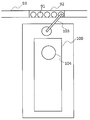
- FIG. 3 is a schematic top view of the electrolyte analysis unit.
- the sample rack 92 containing the sample container 91 is transported to the sample suction position by the transport line 33.
- the sample dispensing probe 103 sucks the sample from the sample container 91 on the sample rack 92, and discharges the sample to the dilution tank 104 of the analysis unit 100 in the electrolyte analysis unit.
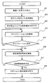
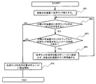
- FIG. 4 is a diagram showing a processing flow of device performance confirmation accompanying execution of the cleaning rack.
- the washing target in the washing rack will be described as an electrolyte analysis unit, but the washing using the washing rack is not limited to the electrolyte analysis unit, and may be the biochemical analysis unit, the immunological analysis unit, or the like.
- the user prepares the washing operation by installing a conditioner for washing the detergent used for washing and removing the influence of the detergent after washing on the washing rack.
- step 201 of FIG. 4 the washing rack is installed in the sample rack loading unit 1 and the rack is transported to any of the analysis units 5 to 8 of the automatic analyzer.
- This is a description of an example in which the main cleaning rack is transported to the electrolyte analysis unit that is the target of cleaning.
- the operation in the electrolyte analysis unit is controlled by the computer in the electrolyte analysis unit.
- step 202 the electrolyte analysis unit starts the cleaning operation.
- the dilution tank is cleaned by discharging the cleaning solution into the dilution tank in the electrolyte analysis unit multiple times to fill the dilution tank with the cleaning solution.
- the flow path cleaning of the electrolyte analysis unit is performed.
- the conditioner installed on the washing rack is used to condition the sample dispensing mechanism, the diluting tank, and the flow path of the electrolyte analysis unit.
- the analysis unit (electrolyte in the example of FIG. 4) is triggered by the time when the cleaning operation is started (that is, when the suction operation of the cleaning liquid on the cleaning rack is started for cleaning the dilution tank).
- the analysis of the patient sample using the analysis unit) is disabled (the sample analysis operation is stopped). Specifically, the transportation of the sample to this analysis unit is stopped. In this case, if the sample is not requested to be analyzed by another analysis unit, the analysis is not possible at this analysis unit, and therefore the sample rack loading section 1
- the sample loaded into the sample rack is collected in the sample rack collecting section 10 without being analyzed by this analysis unit.
- the overall management computer 11 recommends calibration analysis to the control computer of the electrolyte analysis unit, and loads a rack (hereinafter referred to as a calibration rack) in which a container containing the standard solution is installed into the sample rack.
- the display unit 19 displays that the unit 1 is installed.
- the user sets a calibration request and installs the calibration rack in the sample rack loading section 1.
- the calibration rack is transported into the electrolyte analysis unit, and the calibration measurement is performed on the analysis unit (in this embodiment, the electrolyte analysis unit) that has been washed by the washing rack.
- step 205 it is determined whether the calibration was successful.
- step 206 the general management computer 11 controls the analysis unit in order to confirm that the analysis unit maintains the performance satisfying the device specifications.
- the quality control sample analysis is recommended to the computer for display and the fact is displayed on the display unit 19.
- the user sets a request for quality control sample analysis, and installs the rack in which the quality control sample is installed in the sample rack loading section 1.
- a rack with a container containing quality control samples in the rack loading port (hereinafter referred to as quality control rack) is installed in the sample rack loading section 1 and is transported into the automatic analyzer to perform cleaning by the cleaning rack.
- the quality control sample is measured by the analyzed unit (electrolyte analysis unit in this embodiment).
- the control computer in the electrolyte analysis unit determines whether or not the quality control measurement is successful. Quality control If the measurement result value is not within the quality control range, it can be judged that the performance confirmation of this analysis unit has not been completed (the cleaning operation has not completed normally), so the sample analysis operation of the electrolyte analysis unit is stopped. It will be in a state of
- the measurement result value is within the quality control range, it can be determined that the performance confirmation of this analysis unit has been completed, so it is possible to analyze the patient sample in the analysis unit that performed the washing operation with the washing rack in step 208. And That is, the sample can be transported to the analysis unit that has performed the cleaning operation, and the sample can be dispensed into the analysis unit 100 by the sample dispensing probe 103.
- step S207 If the quality control sample measurement result is out of the specification range in step S207, the quality control sample measurement is performed again, or the quality control sample measurement is performed again after re-analyzing the calibration, and the state of the device condition is again determined. Is confirmed (in the process flow of FIG. 4, a method for performing the measurement of the quality control sample again is described).
- the device performance is secured and the correct patient sample result can be output. .. That is, the sample analysis operation of the analysis unit is stopped until it is determined that the performance of the analysis unit is normal based on the cleaning operation.
- the cleaning operation is judged as “failure” and the analysis unit cannot be used until the cleaning operation by the cleaning rack is normally completed again.
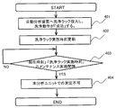
- FIG. 5 is a diagram showing a procedure flow when the cleaning operation by the cleaning rack is not normally completed.
- step 301 a washing rack is installed in the sample rack loading section 1 and this rack is transported to any of the analysis units 5-8.
- the main cleaning rack is transported to the electrolyte analysis unit to be cleaned.
- step 302 the cleaning operation is started by aspirating the cleaning liquid installed in the cleaning rack with the sample dispensing mechanism.
- step 303 After the cleaning operation is completed, it is determined in step 303 whether or not the cleaning operation has been correctly executed. When all the planned cleaning operations are completed normally (completed), the main cleaning operation is stored as “success” in the storage unit of the control computer in the analysis unit and the general management computer 11 in step 304.
- the main cleaning operation is stored as “failure” in step 305. If the washing operation is stored as "failure”, it is determined that the analysis will be affected in this state, and in step 306, subsequent calibration analysis, quality control measurement, and measurement by the main analysis unit including the patient sample are disabled. .. In other words, the control computer in the analysis unit disables the measurement in the analysis unit and stops the measurement operation, and the general management computer 11 is also notified that the measurement in the analysis unit is disabled, The display unit 19 displays that measurement by this analysis unit is disabled.
- the user again loads the washing rack into the sample rack loading unit 1, and the general management computer 11 transports the washing rack to the main analysis unit through the transport line 3, and the main analysis unit executes the operations shown in FIGS. 4 and 5. Then, the cleaning operation using the cleaning rack is performed. This is repeated until the cleaning operation is determined to be “successful”.
- an automatic analyzer capable of maintaining stable apparatus condition and exhibiting stable performance by automatically monitoring the cleaning execution status using a cleaning rack is realized. can do.
- the second embodiment is an example in which a cleaning operation similar to that of the first embodiment is regularly performed by the cleaning rack, and the regular maintenance is surely executed.
- the target analysis unit does not execute the cleaning operation using the cleaning rack within the specified period. , Disable the target analysis unit for analysis.
- FIG. 6 is a diagram showing a procedure of monitoring the cleaning implementation status by the cleaning rack.
- step 401 in FIG. 6 the washing operation using the washing rack is performed on the target analysis unit in the same manner as in the first embodiment to make it “successful”.
- step 402 the date and time of successful maintenance of the washing rack is stored in the general management computer 11 and the control computer of the target analysis unit.
- step 403 the current time is compared with the success time of the cleaning operation by the cleaning rack, and the elapsed time from the previous successful cleaning operation time of the cleaning rack is calculated.
- this elapsed time is compared with the prescribed maintenance execution interval and it is determined that the maintenance execution interval is longer, the analysis unit can continue to be used for analysis. According to the above judgment, even if analysis and use can be continued, it will be necessary for the user to perform the cleaning operation using the cleaning rack soon after a certain time has passed after the cleaning with the previous cleaning rack. The user may be prompted to prepare for the next cleaning by the cleaning rack by displaying it on the screen of the display unit 19 or notifying by an alarm.
- the overall management computer 11 and the control computer of the analysis unit determine that the analysis unit needs to be cleaned by the cleaning rack, and the measurement using the analysis unit is disabled in step 404. To do. At this time, the user may be notified by a screen display of the display unit 19 or an alarm that the cleaning operation by the cleaning rack is necessary.
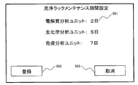
- the specified period may have a fixed value in each analysis unit 5-8, or the maintenance execution period can be changed from the screen of the display unit 19.
- FIG. 7 is a diagram showing a screen example of the display unit 19 in which the maintenance period can be changed.
- a means for changing the cleaning rack maintenance execution period will be described with reference to FIG. 7.
- the setting can be made on a daily basis, but the input may be made on another unit such as “hour”.
- the analysis unit type unit electrophilyte analysis unit, biochemical analysis unit and immunological analysis unit
- only one maintenance execution period common to each analysis unit is defined. Good.
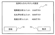
- FIG. 8 is a diagram showing a process flow of cleaning management by the cleaning rack using the number of measurement tests (number of analyzes). A procedure for managing cleaning will be described using the processing flow shown in FIG.
- step 601 of FIG. 8 the washing operation using the washing rack is performed on the corresponding analysis unit in the same manner as in the first embodiment, and “successful” is performed. Then, in step 602, the number of measurement tests (the number of analyzes) of the analysis unit that has performed the cleaning operation by the cleaning rack is reset to zero.
- step 603 when the measurement (analysis) is performed by the analysis unit that has been washed in the washing rack, one is added to the number of measurement tests in step 604.
- step 605 the number of measurement tests is compared with the number of maintenance measurement tests specified by the corresponding analysis unit.
- this analysis unit can continue to be used for analysis.
- the analysis can continue to be used in the above determination, it is displayed on the display unit 19 that the user will soon need to perform a cleaning operation using the cleaning rack when a certain number of tests (constant number of analyzes) is reached.
- the user may be prompted to prepare for the next cleaning by the cleaning rack by displaying it on the screen or notifying by an alarm.
- the overall management control computer (overall management control unit) 11 can notify the user that the cleaning operation by the cleaning rack is necessary, by the screen display of the display unit 19 or an alarm notification. In this case, it is possible to display on the display unit 19 that the cleaning operation is required, before a certain period of time when the cleaning operation by the cleaning rack is required.
- the number of maintenance execution measurement tests may have a fixed value in the automatic analyzer, or the number of maintenance execution analysis tests may be changed from the display screen of the display unit 19 as shown in FIG.
- Input the maintenance measurement measurement test number in the measurement measurement test number setting unit 701 of FIG. 9 it is possible to set the analysis unit type unit (electrolyte analysis unit, biochemical analysis unit, and immunological analysis unit), but only one maintenance execution measurement test may be defined in the automatic analyzer.
- the analysis unit type unit electrophilyte analysis unit, biochemical analysis unit, and immunological analysis unit
- the same effect as in the first embodiment can be obtained, and when the cleaning operation using the cleaning rack is not executed within the specified period in the target analysis unit, the target analysis unit is analyzed. Since it is configured such that it cannot be used, the washing operation using the washing rack for a long time is not executed, and it is possible to avoid performing the analysis despite the change in the apparatus condition.
- Example 3 an example of performing a washing operation without disturbing the analysis of a patient sample when the washing rack is transported into the automatic analyzer while the patient sample is being measured in the automatic analyzer. Will be explained.
- the rack transfer order to the analysis unit differs depending on the analysis request items for the sample and the analysis status of each analysis unit. There are many cases.
- the general management computer 11 confirms the unanalyzed items among the requested items for the sample being measured in the automatic analyzer, and the cleaning is performed using the cleaning rack.
- the washing rack transfer to the analysis unit is temporarily held in the automatic analyzer.
- the cleaning rack temporarily held in the automatic analyzer is transported to the target unit and cleaned. Perform an action.
- FIG. 10 is a diagram showing a flow chart showing a means for optimizing the transportation of the washing rack according to the analysis implementation status in the automatic analyzer.
- step 801 of FIG. 10 the user installs the washing rack in which the washing liquid and the conditioner are placed in the sample rack loading unit 1 of the automatic analyzer.
- step 802 the general management computer 11 of the automatic analyzer determines whether or not a rack other than the washing rack exists in the automatic analyzer. That is, when the general management computer 11 recognizes the existence of the washing rack in the automatic analyzer, the standard solution used for calibration, the quality control sample used for quality control measurement, the patient sample, etc. are installed in the automatic analyzer. Check the presence or absence of the rack that has been installed.
- step 802 if the rack does not exist in the automatic analyzer, the process proceeds to step 805, where the general management computer 11 conveys the cleaning rack to the analysis unit to be cleaned and performs the cleaning operation in the analysis unit to be cleaned. Is started.
- step 802 if there is a rack other than the washing rack in the automatic analyzer, the requested items of the samples on all racks in the automatic analyzer are confirmed in step 803. If there is no unmeasured request item in the wash target analysis unit in the wash rack among the above request items, the wash rack is set as the wash target analysis unit in step 805 even if the rack remains in the automatic analyzer. Carry and carry out cleaning operation.
- step 803 if there is an unmeasured request item in the wash target analysis unit in the wash rack among the above-mentioned request items, the process proceeds to step 804, and the wash rack is temporarily stored in the sample rack standby section 9 in the automatic analyzer. stand by.
- steps 802 and 803 the presence/absence of racks other than the washing rack in the automatic analyzer and the presence/absence of unmeasured request items in the washing target analysis unit are confirmed in steps 802 and 803, respectively. If there is no item to be analyzed in step 1, the transfer of the cleaning rack to the cleaning target analysis unit is started in step 805.
- the cleaning using the cleaning rack of the cleaning target analysis unit is performed by the same operation as that of the first embodiment.
- the user can load the washing rack without being aware of the analysis status of the sample while the automatic analyzer continues the routine analysis.
- Example 4 is an example in which the apparatus condition confirmation after the washing rack is put into operation can be correctly performed.
- the calibration analysis and the quality control sample measurement are successful, so that the analysis unit can perform the measurement.
- the user puts the calibration rack and the quality control rack into the automatic analyzer, and performs the calibration analysis and the quality control sample measurement.
- the calibration rack and the quality control rack which are loaded after the washing rack loaded in the automatic analyzer, should be subjected to calibration analysis and quality control sample measurement after the washing by the washing rack is completed. There is expected.
- the cleaning rack is scheduled to perform the cleaning operation in the first analysis unit and the second analysis unit, but after that, for the standard solution on the calibration rack and the quality control sample on the quality control rack that are put into the automatic analyzer, Request the test items of the second analysis unit only and load the rack.
- the washing rack first performs the washing operation in the first analysis unit, while the calibration rack and quality control rack are first transported to the second analysis unit to perform calibration measurement and quality control sample measurement.
- calibration analysis and quality control sample measurement may be performed before the washing operation by the washing rack.
- washing with a washing rack is performed, calibration analysis and quality control analysis are required again, and the behavior may be different from the user's intention. is there.
- the calibration rack and the quality control sample rack are transported to the automatic analyzer after the washing rack, and the cleaning rack is scheduled to be transported but not transported to the analysis unit to which the calibration rack and the quality control rack are transported next.
- the automatic analyzer the calibration rack and the quality control rack are temporarily kept on standby and the calibration rack and the quality control rack are not transported to the analysis unit. Then, the cleaning rack is transported to the analysis unit, and after all the cleaning operations are completed, the calibration rack and the quality control rack are transported to the analysis unit.
- FIG. 11 is a diagram showing a transfer processing flow of the cleaning rack, the calibration rack, and the quality control rack in the fourth embodiment.
- step 901 of FIG. 11 a washing rack is installed in the sample rack loading section 1 and transported to the automatic analyzer. At that time, the washing rack is started to be transported to the analysis unit to be washed.
- step 902 the calibration rack and the quality control rack are transported to the automatic analyzer by the user, and in step 903, the overall management computer 11 follows the washing rack to the calibration rack and the quality control rack. Check (determine) whether the rack has been loaded.
- step 903 when it is confirmed that the calibration rack and the quality control rack are carried into the automatic analyzer after the washing rack, the general management computer 11 uses the calibration rack and the quality control rack for analysis accompanying the washing rack. Recognize that. Then, in step 904, the transport planned analysis unit of the cleaning rack carried in before the calibration rack and the quality control rack is confirmed.
- step 905 it is determined whether or not the cleaning rack is scheduled to be transported but is not yet transported to the analysis unit to be transported next by the calibration rack and the quality control rack. If the cleaning rack is to be transported but has not been transported, in step 906, the sample rack standby unit 9 in the automatic analyzer temporarily waits.
- step 905 if the cleaning rack has already been transported or is not scheduled to be transported to the analysis unit to be transported by the calibration rack and the quality control rack, the process proceeds to step 907, and the calibration rack and the quality control rack for the target analysis unit. Is carried.
- the general management computer 11 monitors the transportation status of the cleaning rack and the cleaning execution status, the cleaning rack is transported, and the cleaning operation is completed. If the calibration rack and the quality control rack are waiting to be transferred to the specified analysis unit, the calibration rack and the quality control rack are started to be transferred to this analysis unit.
- the same effect as that of the first embodiment is obtained, and after the cleaning operation associated with the cleaning rack is normally completed for the calibration analysis and the quality control sample analysis by the rack transport processing described above. It can be surely executed, and the analysis can be executed in the order intended by the user.
- Example 5 is an example in which it is possible to easily confirm the device condition after the washing rack is loaded.
- Examples 1 to 4 of the present invention after the cleaning operation by the cleaning rack is performed, the calibration analysis and the quality control sample measurement are successful, so that this analysis unit can be used for the measurement. Therefore, when the washing rack is put into the automatic analyzer and the cleaning operation is performed, the user requests the calibration of all the analysis items of the target analysis unit and the quality control sample measurement, and then performs the calibration to the automatic analyzer. By inserting and analyzing the rack in which the standard solution required for analytical measurement and the quality control sample required for quality control sample are placed and analyzed, the analysis unit in which the washing operation is performed by the washing rack can be used.
- the cleaning rack when the calibration rack and the quality control rack are successively transferred to the automatic analyzer after the cleaning rack, the cleaning rack can be transferred and analyzed by the analysis unit to be cleaned. Automatically generate calibration analysis request and quality control measurement request for all items.
- FIG. 12 is a diagram showing a processing flow for automatically generating a calibration analysis request and a quality control measurement request for all items that can be analyzed by the analysis unit.
- step 1001 of FIG. 12 the user installs the washing rack in the sample rack loading unit 1, and the washing rack is loaded into the automatic analyzer.
- step 1002 the user loads the calibration rack and the quality control rack into the sample rack loading unit 1 of the automatic analyzer. Subsequently, in step 1003, the overall management computer 11 determines whether or not the cleaning rack and the calibration rack and the accuracy management rack are successively loaded.
- step 1004 When it is determined in step 1003 that the calibration rack and the quality control rack have been successively loaded into the washing rack, in step 1004, the calibration of items that can be analyzed by the analysis unit that performs the washing operation of the washing rack.
- the overall management computer 11 automatically generates an analysis request and a quality control request.
- cleaning, calibration analysis, and quality control measurement are performed by the same operations as in the first embodiment.
- step 1003 If it is determined in step 1003 that the calibration rack and the quality control rack are not continuously loaded into the washing rack, that is, if the operation of step 1002 is not performed, the operation of step 1004 is not performed. , The processing ends.
- the user continuously installs the calibration rack in which the required standard solution is continuously installed in the washing rack and the quality control sample rack in which the quality control sample is installed, and the rack is installed in the automatic analyzer.
- the user does not have to make a calibration analysis request and a quality control request for the items that can be analyzed by the analysis unit where the cleaning rack performs the cleaning operation, simply by carrying the product, and cleaning, calibration analysis, and quality control measurement can be performed. Is done.
- the same effect as that of the first embodiment can be obtained, and the processing performed by the user can be reduced and the convenience can be improved.
- the automatic analyzer includes a plurality of analysis units of different types, for example, an electrolyte analysis unit, a biochemical analysis unit, and an immunological analysis unit
- a washing rack is provided for each type of analysis unit and is identified. A code or the like is attached. Then, the identification code attached to the washing rack can be read by the ID reading unit 2 and conveyed to the corresponding analysis unit.
- the cleaning liquid installed on the cleaning rack can be commonly used for cleaning different types of analysis units
- this cleaning rack can be transported to multiple analysis units.
- the main cleaning rack may be configured to be sequentially transported from the analysis unit arranged at a position close to the sample rack input port 1.
- the above-described example is an example including a plurality of analysis units, but the first, second, and fifth embodiments can be applied even if the number of analysis units is one.
- the calibration rack holding the standard solution and the quality control rack holding the quality control sample are loaded from the sample rack loading section 1 and transported to the analysis section.
- the present invention can be applied even in the case where the standard solution and the quality control sample are previously stored. In that case, the transportation of the calibration rack and the quality control rack to the analysis unit can be omitted.
- Example rack loading section 2...D reading section, 3...transport line (transport mechanism) 5,6,7,8...analysis unit, 9...sample rack standby section, 10... Sample rack collection unit, 11... Overall management computer, 12, 13, 14, 15, 16... Control computer, 18... Operation unit, 19... Display unit, 20, 21, 22, 23... Reagent dispensing probe, 25, 26... Rail, 30, 31... Stirring device, 35... Reaction container, 36... Reaction disk, 40... Reagent container , 41, 42... Reagent disk, 45... Container cleaning mechanism, 50... Light source, 51, 61, 71, 81... Drawing line (drawing mechanism), 52... Detection optical device, 54 ... Washing port, 60... Controller, 62... Housing, 91... Sample container, 92...
- Sample rack 34, 95, 103... Sample dispensing probe, 100... Analytical unit, 104... Diluting tank, 201-208, 301-306, 401-404, 601-606, 801-805, 901-907, 1001-1004... Processing step, 501... Implementation period setting Section, 502, 702... Registration button, 503, 703... Cancel button, 701... Performed measurement test number setting section
Landscapes
- Engineering & Computer Science (AREA)
- Quality & Reliability (AREA)
- Physics & Mathematics (AREA)
- Health & Medical Sciences (AREA)
- Life Sciences & Earth Sciences (AREA)
- Chemical & Material Sciences (AREA)
- Analytical Chemistry (AREA)
- Biochemistry (AREA)
- General Health & Medical Sciences (AREA)
- General Physics & Mathematics (AREA)
- Immunology (AREA)
- Pathology (AREA)
- Automatic Analysis And Handling Materials Therefor (AREA)
Abstract
La présente invention permet de concevoir un automate d'analyse capable de maintenir un état normal d'un dispositif et de présenter des performances stables en surveillant automatiquement l'état de fonctionnement d'un nettoyage à l'aide d'une cassette de nettoyage. Cet automate d'analyse comprend : au moins une unité d'analyse 5-8 pour analyser un échantillon, une partie d'insertion de portoir 1 dans laquelle au moins un portoir d'échantillons 92 maintenant l'échantillon et une cassette de nettoyage maintenant un liquide de nettoyage sont insérés, un mécanisme de transport 3 pour transporter au moins le portoir d'échantillons 92 et la cassette de nettoyage inséré dans la partie d'insertion de portoir 1 vers l'unité d'analyse 5-8, et une unité de commande et de gestion globale pour commander le fonctionnement de l'unité d'analyse 5-8, de la partie d'insertion de portoir 1 et du mécanisme de transport 3. L'unité de commande et de gestion globale entraîne le transport de la cassette de nettoyage vers l'unité d'analyse 5-8, déclenche une opération de nettoyage pour l'unité d'analyse 5-8 vers laquelle la cassette de nettoyage a été transportée à l'aide du liquide de nettoyage contenu dans celle-ci, et provoque l'arrêt du fonctionnement d'analyse d'échantillon par l'unité d'analyse 5-8 vers laquelle la cassette de nettoyage a été transportée jusqu'à ce que la performance de l'unité d'analyse 5-8 soit déterminée comme étant normale sur la base de l'opération de nettoyage.
Priority Applications (4)
| Application Number | Priority Date | Filing Date | Title |
|---|---|---|---|
| JP2020559859A JP6991363B2 (ja) | 2018-12-11 | 2019-11-14 | 自動分析装置 |
| US17/276,937 US12123884B2 (en) | 2018-12-11 | 2019-11-14 | Monitoring the cleaning status of an automatic analyzer |
| EP19894674.1A EP3896454B1 (fr) | 2018-12-11 | 2019-11-14 | Automate d'analyse |
| CN201980054566.3A CN112585473B (zh) | 2018-12-11 | 2019-11-14 | 自动分析装置 |
Applications Claiming Priority (2)
| Application Number | Priority Date | Filing Date | Title |
|---|---|---|---|
| JP2018231519 | 2018-12-11 | ||
| JP2018-231519 | 2018-12-11 |
Publications (1)
| Publication Number | Publication Date |
|---|---|
| WO2020121726A1 true WO2020121726A1 (fr) | 2020-06-18 |
Family
ID=71076863
Family Applications (1)
| Application Number | Title | Priority Date | Filing Date |
|---|---|---|---|
| PCT/JP2019/044679 Ceased WO2020121726A1 (fr) | 2018-12-11 | 2019-11-14 | Automate d'analyse |
Country Status (5)
| Country | Link |
|---|---|
| US (1) | US12123884B2 (fr) |
| EP (1) | EP3896454B1 (fr) |
| JP (1) | JP6991363B2 (fr) |
| CN (1) | CN112585473B (fr) |
| WO (1) | WO2020121726A1 (fr) |
Cited By (2)
| Publication number | Priority date | Publication date | Assignee | Title |
|---|---|---|---|---|
| WO2022070460A1 (fr) * | 2020-09-29 | 2022-04-07 | 株式会社日立ハイテク | Dispositif d'analyse automatique |
| EP4184174A4 (fr) * | 2020-07-16 | 2024-07-31 | Hitachi High-Tech Corporation | Dispositif d'analyse d'électrolyte |
Families Citing this family (2)
| Publication number | Priority date | Publication date | Assignee | Title |
|---|---|---|---|---|
| JP7560647B2 (ja) * | 2021-03-03 | 2024-10-02 | 株式会社日立ハイテク | 自動分析システム及び検体分配方法 |
| CN114660310B (zh) * | 2022-05-24 | 2022-10-28 | 深圳市帝迈生物技术有限公司 | 样本分析系统的自动定标方法 |
Citations (7)
| Publication number | Priority date | Publication date | Assignee | Title |
|---|---|---|---|---|
| JP2008051765A (ja) | 2006-08-28 | 2008-03-06 | Hitachi High-Technologies Corp | 自動分析装置および自動分析方法 |
| JP2009168730A (ja) * | 2008-01-18 | 2009-07-30 | Hitachi High-Technologies Corp | 自動分析装置 |
| JP2010078477A (ja) * | 2008-09-26 | 2010-04-08 | Olympus Corp | 自動分析装置および分析精度管理表示方法 |
| JP2010204129A (ja) * | 2010-06-25 | 2010-09-16 | Hitachi Ltd | 自動分析装置及びラック搬送方法 |
| JP2012208099A (ja) | 2011-03-30 | 2012-10-25 | Sysmex Corp | 検体分析装置 |
| JP2014016218A (ja) | 2012-07-09 | 2014-01-30 | Hitachi High-Technologies Corp | 自動分析装置 |
| WO2017141626A1 (fr) * | 2016-02-19 | 2017-08-24 | 株式会社日立ハイテクノロジーズ | Dispositif d'analyse automatisé |
Family Cites Families (24)
| Publication number | Priority date | Publication date | Assignee | Title |
|---|---|---|---|---|
| JP3031237B2 (ja) * | 1996-04-10 | 2000-04-10 | 株式会社日立製作所 | 検体ラックの搬送方法及び検体ラックを搬送する自動分析装置 |
| JP3428426B2 (ja) * | 1997-03-26 | 2003-07-22 | 株式会社日立製作所 | 検体分析システム |
| EP0871034B1 (fr) * | 1997-04-10 | 2007-03-07 | Hitachi, Ltd. | Appareil d'analyses automatisé |
| EP0977039B1 (fr) * | 1998-07-27 | 2010-04-07 | Hitachi, Ltd. | Methode de manipulation d' echantillons corporels et appareil d'analyse |
| JP3727481B2 (ja) * | 1999-02-04 | 2005-12-14 | 株式会社日立製作所 | 自動分析方法及び装置 |
| JP2001004639A (ja) * | 1999-06-22 | 2001-01-12 | Hitachi Ltd | 自動分析システム |
| JP3990944B2 (ja) * | 2002-06-28 | 2007-10-17 | 株式会社日立ハイテクノロジーズ | 自動分析装置 |
| JP2004271265A (ja) * | 2003-03-06 | 2004-09-30 | Hitachi High-Technologies Corp | 自動分析装置 |
| JP3931150B2 (ja) * | 2003-03-19 | 2007-06-13 | 株式会社日立ハイテクノロジーズ | 自動分析装置 |
| JP3873039B2 (ja) * | 2003-05-14 | 2007-01-24 | 株式会社日立ハイテクノロジーズ | 自動分析装置 |
| JP4033060B2 (ja) * | 2003-07-17 | 2008-01-16 | 株式会社日立ハイテクノロジーズ | 自動分析装置 |
| JP2008058123A (ja) * | 2006-08-31 | 2008-03-13 | Hitachi High-Technologies Corp | 自動分析装置 |
| JP2008209338A (ja) * | 2007-02-28 | 2008-09-11 | Hitachi High-Technologies Corp | 自動分析装置 |
| JP4557995B2 (ja) * | 2007-02-28 | 2010-10-06 | 株式会社日立ハイテクノロジーズ | 自動分析装置 |
| JP4991586B2 (ja) * | 2008-01-31 | 2012-08-01 | 株式会社日立ハイテクノロジーズ | 自動分析装置 |
| JP2009270869A (ja) * | 2008-05-01 | 2009-11-19 | Hitachi High-Technologies Corp | 自動分析装置 |
| CN102066949B (zh) * | 2008-06-17 | 2013-06-12 | 株式会社日立高新技术 | 自动分析装置 |
| JP5300447B2 (ja) * | 2008-12-04 | 2013-09-25 | ベックマン コールター, インコーポレイテッド | 自動分析装置および自動分析装置における検体分注方法 |
| JP5501205B2 (ja) * | 2010-12-09 | 2014-05-21 | 株式会社日立ハイテクノロジーズ | 自動分析システム |
| JP5912320B2 (ja) * | 2011-07-20 | 2016-04-27 | 株式会社日立ハイテクノロジーズ | 自動分析装置 |
| JP5779062B2 (ja) * | 2011-09-28 | 2015-09-16 | シスメックス株式会社 | 検体処理装置 |
| US9430312B2 (en) * | 2011-10-31 | 2016-08-30 | Hitachi High-Technologies Corporation | Automated analysis system |
| US9470702B2 (en) * | 2012-10-11 | 2016-10-18 | Siemens Healthcare Diagnostics Inc. | Automation maintenance carrier auto-loader |
| CN110325864B (zh) * | 2017-02-22 | 2023-03-28 | 株式会社日立高新技术 | 自动分析装置 |
-
2019
- 2019-11-14 CN CN201980054566.3A patent/CN112585473B/zh active Active
- 2019-11-14 US US17/276,937 patent/US12123884B2/en active Active
- 2019-11-14 EP EP19894674.1A patent/EP3896454B1/fr active Active
- 2019-11-14 WO PCT/JP2019/044679 patent/WO2020121726A1/fr not_active Ceased
- 2019-11-14 JP JP2020559859A patent/JP6991363B2/ja active Active
Patent Citations (7)
| Publication number | Priority date | Publication date | Assignee | Title |
|---|---|---|---|---|
| JP2008051765A (ja) | 2006-08-28 | 2008-03-06 | Hitachi High-Technologies Corp | 自動分析装置および自動分析方法 |
| JP2009168730A (ja) * | 2008-01-18 | 2009-07-30 | Hitachi High-Technologies Corp | 自動分析装置 |
| JP2010078477A (ja) * | 2008-09-26 | 2010-04-08 | Olympus Corp | 自動分析装置および分析精度管理表示方法 |
| JP2010204129A (ja) * | 2010-06-25 | 2010-09-16 | Hitachi Ltd | 自動分析装置及びラック搬送方法 |
| JP2012208099A (ja) | 2011-03-30 | 2012-10-25 | Sysmex Corp | 検体分析装置 |
| JP2014016218A (ja) | 2012-07-09 | 2014-01-30 | Hitachi High-Technologies Corp | 自動分析装置 |
| WO2017141626A1 (fr) * | 2016-02-19 | 2017-08-24 | 株式会社日立ハイテクノロジーズ | Dispositif d'analyse automatisé |
Non-Patent Citations (1)
| Title |
|---|
| See also references of EP3896454A4 |
Cited By (4)
| Publication number | Priority date | Publication date | Assignee | Title |
|---|---|---|---|---|
| EP4184174A4 (fr) * | 2020-07-16 | 2024-07-31 | Hitachi High-Tech Corporation | Dispositif d'analyse d'électrolyte |
| WO2022070460A1 (fr) * | 2020-09-29 | 2022-04-07 | 株式会社日立ハイテク | Dispositif d'analyse automatique |
| JPWO2022070460A1 (fr) * | 2020-09-29 | 2022-04-07 | ||
| JP7397216B2 (ja) | 2020-09-29 | 2023-12-12 | 株式会社日立ハイテク | 自動分析装置 |
Also Published As
| Publication number | Publication date |
|---|---|
| US20220034923A1 (en) | 2022-02-03 |
| EP3896454A1 (fr) | 2021-10-20 |
| EP3896454B1 (fr) | 2024-03-20 |
| CN112585473B (zh) | 2024-01-12 |
| US12123884B2 (en) | 2024-10-22 |
| EP3896454A4 (fr) | 2022-08-31 |
| JP6991363B2 (ja) | 2022-01-12 |
| CN112585473A (zh) | 2021-03-30 |
| JPWO2020121726A1 (ja) | 2021-09-27 |
Similar Documents
| Publication | Publication Date | Title |
|---|---|---|
| JP4932947B2 (ja) | 自動分析装置およびその支援システム | |
| US20080219887A1 (en) | Automatic analyzer | |
| US8758684B2 (en) | Automatic analyzer | |
| JP3889877B2 (ja) | 自動分析装置およびその支援システム | |
| JP3873039B2 (ja) | 自動分析装置 | |
| JP6991363B2 (ja) | 自動分析装置 | |
| JP5331056B2 (ja) | 自動分析装置 | |
| CN102265162A (zh) | 自动分析装置及其支援系统 | |
| JP4217237B2 (ja) | 自動分析装置およびその支援システム | |
| JP2019219228A (ja) | 自動分析装置、および自動分析方法 | |
| JP5031518B2 (ja) | 自動分析装置 | |
| JP6605576B2 (ja) | 自動分析装置 | |
| JP5174629B2 (ja) | 自動分析装置 | |
| US20230341425A1 (en) | Automatic analyzer and dispensing method of reagent | |
| JP2017032500A (ja) | 自動分析装置 | |
| JP4058081B2 (ja) | 自動分析装置、その支援システム、および、記憶媒体 | |
| JP4491505B2 (ja) | 自動分析装置 | |
| US20260043819A1 (en) | Automatic analyzer and control method thereof |
Legal Events
| Date | Code | Title | Description |
|---|---|---|---|
| 121 | Ep: the epo has been informed by wipo that ep was designated in this application |
Ref document number: 19894674 Country of ref document: EP Kind code of ref document: A1 |
|
| ENP | Entry into the national phase |
Ref document number: 2020559859 Country of ref document: JP Kind code of ref document: A |
|
| NENP | Non-entry into the national phase |
Ref country code: DE |
|
| ENP | Entry into the national phase |
Ref document number: 2019894674 Country of ref document: EP Effective date: 20210712 |